EP3899221B1 - Befestigungsvorrichtung für ein modul zur abgabe einer wässrigen lösung in einem tank an bord eines kraftfahrzeuges - Google Patents
Befestigungsvorrichtung für ein modul zur abgabe einer wässrigen lösung in einem tank an bord eines kraftfahrzeuges Download PDFInfo
- Publication number
- EP3899221B1 EP3899221B1 EP20729743.3A EP20729743A EP3899221B1 EP 3899221 B1 EP3899221 B1 EP 3899221B1 EP 20729743 A EP20729743 A EP 20729743A EP 3899221 B1 EP3899221 B1 EP 3899221B1
- Authority
- EP
- European Patent Office
- Prior art keywords
- aqueous solution
- base
- tank
- module
- substantially vertical
- Prior art date
- Legal status (The legal status is an assumption and is not a legal conclusion. Google has not performed a legal analysis and makes no representation as to the accuracy of the status listed.)
- Active
Links
Images
Classifications
-
- F—MECHANICAL ENGINEERING; LIGHTING; HEATING; WEAPONS; BLASTING
- F01—MACHINES OR ENGINES IN GENERAL; ENGINE PLANTS IN GENERAL; STEAM ENGINES
- F01N—GAS-FLOW SILENCERS OR EXHAUST APPARATUS FOR MACHINES OR ENGINES IN GENERAL; GAS-FLOW SILENCERS OR EXHAUST APPARATUS FOR INTERNAL-COMBUSTION ENGINES
- F01N3/00—Exhaust or silencing apparatus having means for purifying, rendering innocuous, or otherwise treating exhaust
- F01N3/08—Exhaust or silencing apparatus having means for purifying, rendering innocuous, or otherwise treating exhaust for rendering innocuous
- F01N3/10—Exhaust or silencing apparatus having means for purifying, rendering innocuous, or otherwise treating exhaust for rendering innocuous by thermal or catalytic conversion of noxious components of exhaust
- F01N3/18—Exhaust or silencing apparatus having means for purifying, rendering innocuous, or otherwise treating exhaust for rendering innocuous by thermal or catalytic conversion of noxious components of exhaust characterised by methods of operation; Control
- F01N3/20—Exhaust or silencing apparatus having means for purifying, rendering innocuous, or otherwise treating exhaust for rendering innocuous by thermal or catalytic conversion of noxious components of exhaust characterised by methods of operation; Control specially adapted for catalytic conversion
- F01N3/206—Adding periodically or continuously substances to exhaust gases for promoting purification, e.g. catalytic material in liquid form, NOx reducing agents
- F01N3/2066—Selective catalytic reduction [SCR]
-
- F—MECHANICAL ENGINEERING; LIGHTING; HEATING; WEAPONS; BLASTING
- F01—MACHINES OR ENGINES IN GENERAL; ENGINE PLANTS IN GENERAL; STEAM ENGINES
- F01N—GAS-FLOW SILENCERS OR EXHAUST APPARATUS FOR MACHINES OR ENGINES IN GENERAL; GAS-FLOW SILENCERS OR EXHAUST APPARATUS FOR INTERNAL-COMBUSTION ENGINES
- F01N2530/00—Selection of materials for tubes, chambers or housings
- F01N2530/18—Plastics material, e.g. polyester resin
-
- F—MECHANICAL ENGINEERING; LIGHTING; HEATING; WEAPONS; BLASTING
- F01—MACHINES OR ENGINES IN GENERAL; ENGINE PLANTS IN GENERAL; STEAM ENGINES
- F01N—GAS-FLOW SILENCERS OR EXHAUST APPARATUS FOR MACHINES OR ENGINES IN GENERAL; GAS-FLOW SILENCERS OR EXHAUST APPARATUS FOR INTERNAL-COMBUSTION ENGINES
- F01N2610/00—Adding substances to exhaust gases
- F01N2610/02—Adding substances to exhaust gases the substance being ammonia or urea
-
- F—MECHANICAL ENGINEERING; LIGHTING; HEATING; WEAPONS; BLASTING
- F01—MACHINES OR ENGINES IN GENERAL; ENGINE PLANTS IN GENERAL; STEAM ENGINES
- F01N—GAS-FLOW SILENCERS OR EXHAUST APPARATUS FOR MACHINES OR ENGINES IN GENERAL; GAS-FLOW SILENCERS OR EXHAUST APPARATUS FOR INTERNAL-COMBUSTION ENGINES
- F01N2610/00—Adding substances to exhaust gases
- F01N2610/10—Adding substances to exhaust gases the substance being heated, e.g. by heating tank or supply line of the added substance
-
- F—MECHANICAL ENGINEERING; LIGHTING; HEATING; WEAPONS; BLASTING
- F01—MACHINES OR ENGINES IN GENERAL; ENGINE PLANTS IN GENERAL; STEAM ENGINES
- F01N—GAS-FLOW SILENCERS OR EXHAUST APPARATUS FOR MACHINES OR ENGINES IN GENERAL; GAS-FLOW SILENCERS OR EXHAUST APPARATUS FOR INTERNAL-COMBUSTION ENGINES
- F01N2610/00—Adding substances to exhaust gases
- F01N2610/14—Arrangements for the supply of substances, e.g. conduits
- F01N2610/1406—Storage means for substances, e.g. tanks or reservoirs
-
- F—MECHANICAL ENGINEERING; LIGHTING; HEATING; WEAPONS; BLASTING
- F01—MACHINES OR ENGINES IN GENERAL; ENGINE PLANTS IN GENERAL; STEAM ENGINES
- F01N—GAS-FLOW SILENCERS OR EXHAUST APPARATUS FOR MACHINES OR ENGINES IN GENERAL; GAS-FLOW SILENCERS OR EXHAUST APPARATUS FOR INTERNAL-COMBUSTION ENGINES
- F01N2610/00—Adding substances to exhaust gases
- F01N2610/14—Arrangements for the supply of substances, e.g. conduits
- F01N2610/1433—Pumps
-
- Y—GENERAL TAGGING OF NEW TECHNOLOGICAL DEVELOPMENTS; GENERAL TAGGING OF CROSS-SECTIONAL TECHNOLOGIES SPANNING OVER SEVERAL SECTIONS OF THE IPC; TECHNICAL SUBJECTS COVERED BY FORMER USPC CROSS-REFERENCE ART COLLECTIONS [XRACs] AND DIGESTS
- Y02—TECHNOLOGIES OR APPLICATIONS FOR MITIGATION OR ADAPTATION AGAINST CLIMATE CHANGE
- Y02A—TECHNOLOGIES FOR ADAPTATION TO CLIMATE CHANGE
- Y02A50/00—TECHNOLOGIES FOR ADAPTATION TO CLIMATE CHANGE in human health protection, e.g. against extreme weather
- Y02A50/20—Air quality improvement or preservation, e.g. vehicle emission control or emission reduction by using catalytic converters
-
- Y—GENERAL TAGGING OF NEW TECHNOLOGICAL DEVELOPMENTS; GENERAL TAGGING OF CROSS-SECTIONAL TECHNOLOGIES SPANNING OVER SEVERAL SECTIONS OF THE IPC; TECHNICAL SUBJECTS COVERED BY FORMER USPC CROSS-REFERENCE ART COLLECTIONS [XRACs] AND DIGESTS
- Y02—TECHNOLOGIES OR APPLICATIONS FOR MITIGATION OR ADAPTATION AGAINST CLIMATE CHANGE
- Y02T—CLIMATE CHANGE MITIGATION TECHNOLOGIES RELATED TO TRANSPORTATION
- Y02T10/00—Road transport of goods or passengers
- Y02T10/10—Internal combustion engine [ICE] based vehicles
- Y02T10/12—Improving ICE efficiencies
Definitions
- the invention relates to a fixing device for a module for dispensing aqueous solution contained in a tank on board a motor vehicle, a module for dispensing aqueous solution contained in a tank on board a motor vehicle comprising said fixing device and an aqueous solution tank on board a vehicle comprising said module. More particularly, the invention relates to a method of manufacturing a fastening device for a module for dispensing aqueous solution contained in a tank on board a motor vehicle.
- the invention can be used in particular in the field of depollution of motor vehicle exhaust gases requiring the use of a urea solution but also in the field of the injection of water into the intake circuit. of air from a vehicle's engine.
- this water mixes with the intake gas and makes it possible to reduce the combustion temperatures and the emissions of pollutants called NOx, and to increase the performance, for example, of an engine. gasoline by reducing sensitivity to knocking.
- the storage system for an aqueous solution for a motor vehicle comprises, in the reservoir, heating means provided to prevent freezing of the urea solution or of the water, preferably demineralised water.
- these heating means are deactivated when the vehicle is stopped after a period of driving and, when the vehicle is parked outside in severe winter external conditions, which can reach for example temperatures of the order of -40°C, the transformation into ice of the urea solution or water, preferably demineralised water, contained in the tank begins and can lead to the freezing of all of the urea solution or water, preferably demineralized water, in a few tens of minutes.
- WO 2008/138960 discloses an aqueous urea solution delivery module comprising flexible heating means.
- a flexible heater poses the problem of its attachment within the module, but also of the attachment of said module to the reservoir, the flexible heater possibly being damaged during assembly of the aqueous urea solution distribution module within the reservoir.
- the document US 9,702,287 B2 discloses a fixing device for a module for dispensing aqueous urea solution contained in a tank on board a motor vehicle, said fixing device comprising non-flexible heating means, said heating means consisting of a heat comprising at least one heating element of the CPT (Positive Temperature Coefficient) type.
- the non-flexible heating medium disclosed in the document US 9,702,287 B2 is overmoulded with a plastic material in HDPE.
- the aqueous urea solution distribution module does not include all or part of the heat diffuser element. Such a module has the disadvantage of requiring a large number of sealing means between the different parts of said module and requires the presence of an additional driver.
- the object of the invention is in particular to overcome these drawbacks of the prior art.
- one objective of the invention in at least one of its embodiments, is to provide a fixing device for a module for dispensing aqueous solution contained in a tank on board a motor vehicle requiring a reduced number of accessories including sealing means or heating means.
- the invention in at least one of its embodiments, also aims to provide a module for dispensing aqueous solution contained in a tank on board a motor vehicle, but also a tank of aqueous solution for a motor vehicle.
- Another objective of the invention in at least one of its embodiments, is to implement a method for manufacturing a fastening device for a module for dispensing aqueous solution contained in a tank on board a vehicle automobile.
- the invention relates to a fixing device for a module for dispensing aqueous solution contained in a tank on board a motor vehicle.
- such a fixing device comprising a pump stator, a heating means and a heat diffuser comprising a base and a first plurality of walls substantially vertical with respect to said base defining at least a first internal volume, said base and/or at least one substantially vertical wall with respect to the base comprising at least one means for positioning the pump stator and/or a first means for fixing the pump stator and/or at least one second means for fixing the means heater, the pump stator and heat diffuser assembly being overmolded by a plastic material, the fastening device comprising at least one first through hole, preferably at the level of the base of the fixing device, more preferably at the level of the heat diffuser, capable of evacuating the aqueous solution pumped by the pump and a second through hole capable of supplying the pump with aqueous solution.
- the general principle of the invention is based on an optimization of the diffusion of the heat emitted by the heating means, but also by the stator of the pump, also allowing a reduction in the number of sealing means such as seals for example.
- the invention is based on an entirely new and inventive approach to producing a fixing device for a module for dispensing aqueous solution contained in a tank on board a motor vehicle composed of an assembly overmolded by a material plastic comprising a pump stator and a heat diffuser, the fixing device comprising at least a first through hole, preferably at the level of the base of the fixing device, capable of evacuating the water pumped by the pump, said diffuser heat comprising at least a first means for fixing the pump stator and / or at least a second means for fixing the heating means.
- a first plurality of walls substantially vertical with respect to said base defining at least a first internal volume is meant the fact that the base and the first plurality of walls substantially vertical with respect to the base form an outline the upper part of which corresponds to the plane passing through the greatest number of upper edges of the substantially vertical walls of the first plurality of substantially vertical walls, said contour defining a first internal volume in combination with the base and the first plurality of substantially vertical walls.
- the upper edges of the plurality of substantially vertical walls with respect to the base can be connected together in whole or in part by a lid.
- Said first plurality of substantially vertical walls may consist of substantially vertical walls in continuity with one another or of substantially vertical walls partially or totally discontinuous from one another, such as for example walls provided with slots over part or all of their height, said height being defined relative to the base.
- the first internal volume is defined by all the substantially vertical walls constituting said first plurality, the voids between the walls being replaced by imaginary walls, the first internal volume also being defined by the base and by the upper part corresponding to the plane passing through the greatest number of upper edges of the substantially vertical walls of the first plurality of substantially vertical walls.
- aqueous solution is intended to denote an aqueous solution containing urea or water, preferably demineralized water.
- demineralized water is meant an aqueous solution having an electrical conductivity less than or equal to 100 ⁇ S/cm at 25° C., or even less than or equal to 50 ⁇ S/cm at 25° C., preferably less than or equal to at 5 ⁇ S/cm at 25°C.
- lower(s) or upper(s) are defined with respect to the final location of the fixing device within the vehicle and are defined taking the ground as a reference.
- a lower edge of an element being closer to the ground than an upper edge of the same element or wall.
- the "at least one substantially vertical wall comprising at least one means for positioning the pump stator and/or a first means for fixing the pump stator and/or at least one second means for fixing the heating means” may be a wall forming part of the first plurality of substantially vertical walls with respect to said base defining at least a first internal volume or else being distinct from this first plurality of substantially vertical walls.
- said substantially vertical wall may have the shape of a stud with a view to its insertion into a receptacle zone of said stud within the pump stator.
- said substantially vertical wall may have the shape of a receptacle zone capable of receiving a lug present on the pump stator.
- the fixing device for the aqueous solution distribution module contained in a tank on board a motor vehicle is such that the heating means is chosen from among a heating resistor, a heating element of the CPT type (Coefficient Positive Temperature Coefficient) and a heat transfer fluid circulation loop, preferably a heating element of the CPT (Positive Temperature Coefficient) type.
- the heating means is chosen from among a heating resistor, a heating element of the CPT type (Coefficient Positive Temperature Coefficient) and a heat transfer fluid circulation loop, preferably a heating element of the CPT (Positive Temperature Coefficient) type.
- the heat transfer fluid circulation loop makes it possible to supply significant power with a “regulated” fluid at inlet temperature (typically at a maximum of 120°C).
- a “regulated” fluid at inlet temperature typically at a maximum of 120°C.
- the CPTs make it possible to integrate a high power and to benefit from self-regulation according to the temperature of the module, the aqueous solution and the level of filling (to avoid the risks of overheating and degradation of components).
- the fixing device for an aqueous solution distribution module contained in a tank on board a motor vehicle according to the invention is such that at least one element of the pump stator is in contact with the heat diffuser.
- Such an embodiment makes it possible to recover the energy dissipated by the heating of the pump and to use it to heat the aqueous solution.
- At least one element of the pump stator is in contact with the heat diffuser
- the fact that at least one element of the pump stator touches the heat diffuser is meant the fact that at least one element of the pump stator touches the heat diffuser.
- the fixing device for an aqueous solution distribution module contained in a tank on board a motor vehicle is such that the pump stator, the heating means and the heat diffuser comprising a base and a first plurality of substantially vertical walls with respect to said base defining at least a first internal volume, said base and/or at least one substantially vertical wall comprising at least a first means for fixing the pump stator and/or at least one second fixing means of the heating means, are overmolded by a plastic material.
- dry zone is intended to denote the fact that the aqueous solution is not present in said zone.
- the fastening device for a module for dispensing aqueous solution contained in a tank on board a motor vehicle is such that it comprises on an outer part a tip in fluid communication with the first through hole able to evacuate the water pumped by the pump.
- this end piece allows easier attachment of the injection line for the aqueous urea solution in the case of a motor vehicle exhaust gas pollution control system or else for water in the case of the injection of water into the combustion chamber of a heat engine of a motor vehicle.
- the fixing device for an aqueous solution dispensing module contained in a tank on board a motor vehicle according to the invention is such that the second means for fixing the heating means is a receptacle present in at least one substantially vertical wall of the heat diffuser relative to the base, said receptacle not being in contact with the aqueous solution.
- the term "receptacle” is intended to denote the fact that the second means for fixing the heating means is capable of receiving the heating means.
- the receptacle may be provided with guide means allowing easy insertion of the heating means. Such a guide means can for example be a slide system.
- the receptacle may also include locking means preventing easy release of the heating means from the receptacle.
- the receptacle may be in the form of a pocket.
- the heating means can be easily assembled, before or after overmoulding.
- the fixing device for an aqueous solution dispensing module contained in a tank on board a motor vehicle is such that a second plurality of substantially vertical walls with respect to said base defines a second internal volume, the second internal volume being inscribed in the first internal volume, said second internal volume serving as a housing for the pump stator.
- a second plurality of walls substantially vertical with respect to said base defines a second internal volume
- the base and the second plurality of walls substantially vertical with respect to the base form an outline whose upper part corresponds to the plane passing through the greatest number of upper edges of the substantially vertical walls of the second plurality of substantially vertical walls, said contour defining a second internal volume in combination with the base and the second plurality of substantially vertical walls.
- Said second plurality of substantially vertical walls may consist of substantially vertical walls in continuity with one another or of substantially vertical walls partially or totally discontinuous from one another, such as for example walls provided with slots over part or all of their height, said height being defined relative to the base.
- the second plurality of substantially vertical walls consists of substantially vertical walls in continuity with one another.
- the second internal volume is defined by all the substantially vertical walls constituting said second plurality, the voids between the walls of the second plurality being replaced by imaginary walls, the second internal volume also being defined by the base and by the upper part corresponding to the plane passing through the greatest number of upper edges of the substantially vertical walls of the second plurality of substantially vertical walls.
- the pump stator is force-fitted into the second internal volume, the dimensions of said pump stator being such that its volume is substantially equal to said second internal volume.
- the fixing device for an aqueous solution dispensing module contained in a tank on board a motor vehicle according to the invention is such that the first plurality of substantially vertical walls comprises at least one housing capable of receive a connection for a jet pump.
- the jet pump makes it possible to fill the first internal volume in order to guarantee the pumping of the aqueous solution.
- the “dynamic dead volume” is reduced thanks to the use of the substantially vertical walls and the jet pump.
- the expression “dynamic dead volume” is intended to designate the volume of non-drawable aqueous solution in the tank under driving conditions (when there are movements of liquid towards the off-center zones of the tank).
- the addition of a “bowl” or “trap” created by the presence of the first plurality of substantially vertical walls around the pump makes it possible to reduce this dynamic dead volume by conserving part of the aqueous solution in this "bowl or “trap”.
- the fixing device for a module for dispensing aqueous solution contained in a tank on board a motor vehicle according to the invention is such that the first plurality of substantially vertical walls and/or the base of the diffuser heat sink includes at least a fourth overmolding through-hole.
- the fourth overmolding through-hole is only intended for a better mechanical grip between the plastic material and the heat diffuser.
- the fourth through-molding hole is no longer apparent once the plastic material has been molded over and the fixing device for the aqueous solution dispensing module contained in a tank on board a motor vehicle has been formed.
- the fixing device for a module for dispensing aqueous solution contained in a tank on board a motor vehicle is such that it comprises means for fixing to said tank, said fixing means being selected from a solder curb, a camlock interface (in French, with cam connection), a mason jar (in French, Mason-type pot), a mechanical assembly with seal, preferably the means of fixing to said tank being a welding pavement.
- soldering via the solder board makes it possible to reduce the number of components and therefore reduce costs, but also to obtain a more compact system, the solder interface is also more compact than a mechanical assembly.
- the fixing device for an aqueous solution dispensing module contained in a tank on board a motor vehicle is such that the heat diffuser comprising a base and a first plurality of walls substantially vertical with respect to said base defining at least a first internal volume, the first means for fixing the pump stator and the second means for fixing the heating means is a single piece.
- the diffuser is made in one piece, which reduces costs, simplifies positioning and maintenance in the overmolding mold.
- the fixing device for an aqueous solution dispensing module contained in a tank on board a motor vehicle is such that the heat diffuser comprising a base and a first plurality of walls substantially vertical relative to said base defining at least a first internal volume is based on aluminum, preferably anodized aluminum.
- the expression “based on aluminium” is intended to denote the fact that the diffuser comprises at least 50% by weight of aluminium, preferably 75% by weight of aluminium, more preferably 90% by weight of aluminium.
- the thermal conductivity and the processing properties of the diffuser are optimized.
- the fixing device for a module for dispensing aqueous solution contained in a tank on board a motor vehicle according to the invention is such that the second through hole capable of supplying the pump with aqueous solution is located in an upper part of the first plurality of substantially vertical walls with respect to said base defining at least a first internal volume.
- the periphery of the second through-hole consists of the upper edges of the first plurality of substantially vertical walls with respect to said base.
- such an embodiment allows the overflow of the solution sucked in by the jet pump in operation, the expansion of the ice when freezing and the filling directly from the first internal volume during filling when the filling means opens above the module.
- the fixing device for a module for dispensing aqueous solution contained in a tank on board a motor vehicle is such that the second through hole capable of supplying the pump with solution aqueous is located on a wall of the first plurality of substantially vertical walls with respect to said base defining at least a first internal volume.
- Such an embodiment makes it possible to ensure a minimum filling level of the module if the filling means does not open above the module.
- the size of the orifice is determined in order to limit the flow rate leaving the first internal volume in operation, typically to approximately 10 kg/h.
- the fixing device for a module for dispensing aqueous solution contained in a tank on board a motor vehicle is such that it comprises a third through hole capable of supplying the pump with solution aqueous, said third through hole being located on a wall of the first plurality of substantially vertical walls with respect to said base defining at least a first internal volume.
- this third through hole can be connected to the suction zone of the jet pump in order to bring the aqueous solution located around the first internal volume into the module.
- the fixing device for an aqueous solution dispensing module contained in a tank on board a motor vehicle is such that it comprises a common electrical connection means for the assembly consisting the heating means and the pump.
- connection means can be used to connect the module to the electrical circuit of the vehicle, which makes it possible to obtain reduced space and costs.
- the overmolding plastic material is a plastic material selected from the group of plastic materials based on polyoxymethylene (POM), polyphenylene sulfide (PPS), polyamide (PA) such as polyphthalamide (PPA), polyetheretherketone (PEEK) , polyamide imide (PAI), polyaryletherketone (PAEK), polyketone (PK) or polyolefin, preferably polyethylene (PE), more preferably high density polyethylene (HDPE).
- POM polyoxymethylene
- PPS polyphenylene sulfide
- PA polyamide
- PPA polyphthalamide
- PEEK polyetheretherketone
- PAI polyamide imide
- PAEK polyaryletherketone
- PK polyketone
- PE polyethylene
- PE high density polyethylene
- the plastic material selected will be a material chemically compatible with the plastic material constituting the reservoir such as a polyolefin, preferably polyethylene (PE), more preferably high density polyethylene (HDPE).
- PE polyethylene
- HDPE high density polyethylene
- group of plastic materials based on is meant the fact that the plastic material comprises at least 50% by weight of the selected plastic material.
- chemically compatible plastic material with another plastic material means that the plastic materials each comprise chemical species that can be welded together, without requiring the addition of additional material.
- chemically compatible plastic materials are capable of bonding intimately together by fusion, and in particular of producing molecular entanglement of polymer chains between them.
- the welding of the two plastic materials is understood as bringing the two plastic materials into contact in such a way that the phenomenon of self-healing occurs at the point of contact.
- the phenomenon of self-healing is produced by the supply of heat to the place of contact.
- a welding operation of two materials under the action of heat is called heat welding.
- welding is used synonymously with "heat sealing”.
- thermoplastic polymer-thermoplastic polymer contact is achieved at the interface, intermolecular diffusion and entanglement is required to complete the process and form a good weld.
- Such a self-healing phenomenon is for example described in the publication "Plastics and Composites Welding Handbook", ISBN 1-56990-313-1, page 23 .
- substantially vertical wall and through hole are common to the heat diffuser as well as to the fixing device for the heat distribution module. aqueous solution contained in a tank on board a motor vehicle.
- fourth through hole which is specific to the heat diffuser, the said hole(s) being filled with plastic material after overmoulding. It is obvious to those skilled in the art that certain substantially vertical wall(s) with respect to the base present in the fixing device may be absent from the inserted heat diffuser. within it by overmoulding.
- a second object of the invention is to provide a module for dispensing aqueous solution contained in a tank on board a motor vehicle comprising a fixing device according to the invention, said module comprising a pump rotor inserted within the stator pump.
- a third object of the invention relates to a reservoir comprising a module for dispensing aqueous solution contained in a reservoir on board a motor vehicle according to the invention.
- the step of manufacturing the heat diffuser comprises a shaping step, the latter being able to be done by stamping, by bending, by cutting and welding or else by die casting.
- the shaping step is carried out by die casting.
- the step of placing the stator within the first internal volume may comprise inserting the pump stator by force mounting, the dimensions of the pump stator being substantially equal to the dimensions of the first means for fixing the pump stator, more particularly when the first means for fixing the pump stator corresponds to a second plurality of substantially vertical walls with respect to the base defining a second internal volume.
- the means for positioning the pump stator and the first means for fixing the stator pump are merged and consist of a second plurality of substantially vertical walls with respect to the base defining a second internal volume.
- the overmolding step may also include the overmolding of the heating means(s) integrated into the pump stator - heat diffuser assembly, the said heating means(s) being placed in the receptacle(s) provided for this purpose.
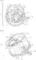
- the fixing device 1 comprises a fixing means 2 to the tank, said fixing means 2 being a weld pad.
- the fixing device 1 also comprises at least a first internal volume 3 and a second internal volume 4, the second internal volume 4 comprising the pump stator as well as a zone for inserting the pump rotor 5 and means for fixing said pump rotor 6.
- the fixing device 1 comprises at least a first through hole 7 at the level of the base 8 of the fixing device, able to evacuate the aqueous solution pumped by the pump and a second through hole 9 able to supply the pump in aqueous solution.
- the first through hole 7 is in fluid communication with an outer part forming an end piece 10.
- the second through hole 9 capable of supplying the pump with aqueous solution is located in an upper part of the first internal volume, the periphery of the second through hole 9 is consisting of the upper edges of the first plurality of walls substantially vertical with respect to the base 8.
- the fixing device 1 also comprises a housing 11 able to receive a connection for a jet pump. The latter can also be provided with a focusing tube 12 for a level sensor.
- the figure 2 presents a side view of the fixing device 1 for a module for dispensing aqueous solution contained in a tank on board a motor vehicle according to the invention presented at figure 1 .
- the fixing device 1 comprises a fixing means 2 to the tank, said fixing means 2 being a weld pavement.
- the fixing device 1 also comprises at least a first internal volume 3 and a second internal volume 4, the second internal volume 4 comprising the pump stator as well as a zone for inserting the pump rotor 5 and means for fixing said pump rotor 6.
- a first through hole 7 is in fluid communication with an outer part forming an end piece 10.
- a second through hole 9 allows the pump to be supplied with aqueous solution.
- the second through hole 9 capable of supplying the pump with aqueous solution is located in an upper part of the first internal volume, the periphery of the second through hole 9 consists of the upper edges of the first plurality of substantially vertical walls with respect to the base.
- the fixing device 1 also comprises a housing 11 capable of receiving a connection for a jet pump. The latter can also be provided with a focusing tube 12 for a level sensor.
- the fixing device 1 is also provided with a third through-hole 13 capable of supplying the pump with aqueous solution, said third through-hole 13 being located on a wall of the first plurality of substantially vertical walls with respect to said base defining the first internal volume 3. This third hole crossing is connected to the suction zone of the jet pump in order to bring in the aqueous solution located around the first internal volume 3 in the module.
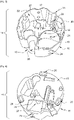
- the picture 3 illustrates a heat diffuser 14 seen before overmolding with a plastic material, said heat diffuser 14 being incorporated in the fixing device for a module for dispensing aqueous solution contained in a tank on board a motor vehicle according to the invention such as presented to figures 1 and 2 .
- the heat diffuser 14 comprises a base 15 and a first plurality of substantially vertical walls 16 with respect to said base 15 defining at least a first internal volume 17, said base 15 comprising at least one means for positioning the pump stator 18 and a first means for fixing the pump stator 19.
- At least one substantially vertical wall 16 of the heat diffuser 14 with respect to the base 15 comprises at least one second means 20 for fixing the heating means
- the heat diffuser 14 comprises at least a first through hole 21, preferably at the level of the base 15 and a second through hole 22.
- the second through hole 22 is located in an upper part of the first internal volume 17, the periphery of the second through hole 22 consists of the upper edges of the first plurality of substantially vertical walls 16 with respect to the base 15.
- the heat diffuser 14 is also provided with a third through hole t 23, said third through-hole 23 being located on a wall of the first plurality of substantially vertical walls 16 with respect to the base 15 defining the first internal volume 17.
- the heat diffuser 14 is provided with at least one fourth through-hole molding 24, preferably a plurality of fourth through-molding holes 24, at the level of the first plurality of substantially vertical walls 16 and/or the base 15 of the heat diffuser 14.
- the first plurality of substantially vertical walls 16 by relative to the base 15 also comprises a housing 25 capable of receiving a connection for a jet pump when the heat diffuser is overmolded, said housing 25 being in the form of a groove.
- the first plurality of substantially vertical walls also includes a housing 26 able to form a focusing tube for a level sensor.
- the heat diffuser 14 also comprises a third plurality of substantially vertical walls 27 with respect to the base 15, said third plurality of substantially vertical walls 27 being closed at the top and comprising a fourth fixing means capable of serving as a housing for a means heater located near the pump stator.
- the figure 4 describes the heat diffuser 14 of the picture 3 seen from its base 15.
- the first plurality of substantially vertical walls 16 comprises at least one second means 20 for fixing the heating means.
- the heat diffuser 14 also comprises a third plurality of substantially vertical walls 27, said third plurality of substantially vertical walls 27 being closed at the top and comprising a fourth fixing means 28 capable of serving as a housing for a heating means located near the pump stator. It is observed that the first plurality of substantially vertical walls 16 with respect to the base 15 has a plurality of fourth overmolding through-holes 24.
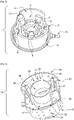
- the figure 5 presents another embodiment of the fixing device 1 for the aqueous solution dispensing module contained in a tank on board a motor vehicle according to the invention.
- the fixing device 1 comprises a fixing means 2 to the tank, said fixing means 2 being a weld pad.
- the fixing device 1 also comprises at least a first internal volume 3 and a second internal volume 4, the second internal volume 4 comprising the pump stator as well as a zone for inserting the pump rotor 5 and means for fixing said pump rotor 6.
- the fixing device 1 comprises at least a first through hole (not shown in the figure) at the level of the base 8 of the fixing device, capable of evacuating the aqueous solution pumped by the pump and a second through hole 9 capable of supplying the pump with an aqueous solution.
- the first through hole is in fluid communication with an outer part forming an end piece 10.
- the second through hole 9 capable of supplying the pump with aqueous solution is located in an upper part of the first internal volume, the periphery of the second through hole 9 consists upper edges of the first plurality of substantially vertical walls with respect to the base 8.
- the fixing device 1 also comprises a housing 11 capable of receiving a connection for a jet pump. The latter can also be provided with a focusing tube 12 for a level sensor.
- the figure 6 illustrates a heat diffuser 14 seen before overmolding with a plastic material, said heat diffuser 14 being incorporated in the fixing device for a module for dispensing aqueous solution contained in a tank on board a motor vehicle according to the invention such as presented to the figure 5 .
- the heat diffuser 14 comprises a base 15 and a first plurality of substantially vertical walls 16 with respect to said base 15 defining at least a first internal volume 17, said base 15 comprising at least one means for positioning the pump stator 18 and a first means for fixing the pump stator 19.
- the means for positioning the pump stator 18 and the first means for fixing the pump stator 19 coincide and consist of a second plurality of substantially vertical walls 29 with respect to the base 15 defining a second internal volume 30, the second internal volume being inscribed in the first internal volume 17, said second internal volume 30 serving as a housing for the pump stator.
- At least one substantially vertical wall 16 of the heat diffuser 14 comprises at least one second fixing means 20 of the heating means, the heat diffuser 14 comprises at least one first through hole 21, preferably at the level of the base 15 and a second through hole 22
- the second through-hole 22 is located in an upper part of the first internal volume 17, the periphery of the second through-hole 22 consists of the upper edges of the first plurality of substantially vertical walls 16 with respect to the base 15.
- the heat diffuser 14 is provided with at least one fourth through-molding hole 24, preferably with a plurality of fourth through-molding holes 24, at the level of the first plurality of substantially vertical walls 16 and/or of the base 15 of the heat diffuser 14.
- the first plurality of substantially vertical walls 16 with respect to the base 15 also comprises a housing 25 capable of receiving a connection. nt for a jet pump when the heat diffuser is molded, said housing 25 being in the form of a groove.
- the first plurality of substantially vertical walls also includes a housing 26 capable of forming a focusing tube 12 for a level sensor.
- the figure 7 describes the heat diffuser 14 of the figure 6 seen from its base 15.
- the first plurality of substantially vertical walls 16 comprises at least one second means 20 for fixing the heating means. It is observed that the first plurality of substantially vertical walls 16 with respect to the base 15 has a plurality of fourth overmolding through-holes 24.
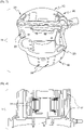
- the figure 8 presents a cross section of the fixing device 1 for the aqueous solution dispensing module contained in a tank on board a motor vehicle according to the invention presented at figure 5 .
- This cross-sectional view of the fixing device 1 illustrates the plastic molding of the pump stator 31 and the heat diffuser 14.
Landscapes
- Engineering & Computer Science (AREA)
- Chemical & Material Sciences (AREA)
- Chemical Kinetics & Catalysis (AREA)
- Mechanical Engineering (AREA)
- Toxicology (AREA)
- Combustion & Propulsion (AREA)
- Health & Medical Sciences (AREA)
- General Engineering & Computer Science (AREA)
- Structures Of Non-Positive Displacement Pumps (AREA)
- Exhaust Gas After Treatment (AREA)
- Cooling, Air Intake And Gas Exhaust, And Fuel Tank Arrangements In Propulsion Units (AREA)
- Air-Conditioning For Vehicles (AREA)
- Details Of Reciprocating Pumps (AREA)
Claims (12)
- Befestigungsvorrichtung für ein Modul zur Abgabe einer wässrigen Lösung, die in einem Tank an Bord eines Kraftfahrzeugs (1) enthalten ist, wobei die Befestigungsvorrichtung (1) aufweist: einen Pumpenstator (31), ein Heizmittel und einen Wärmediffusor (14), der eine Basis (15) und eine erste Mehrzahl von relativ zu der Basis (15) im Wesentlichen vertikalen Wänden (16), die wenigstens ein erstes Innenvolumen (3, 17) definiert, aufweist, wobei die Basis (15) und/oder wenigstens eine relativ zu der Basis (15) im Wesentlichen vertikale Wand wenigstens ein Mittel (18) zum Positionieren des Pumpenstators und/oder ein erstes Mittel (19) zum Befestigen des Pumpenstators und/oder wenigstens ein zweites Mittel (20) zum Befestigen des Heizmittels aufweisen, wobei die Befestigungsvorrichtung dadurch gekennzeichnet ist, dass die Anordnung aus Pumpenstator (31) und Wärmediffusor (14) mit einem Kunststoff umspritzt ist, wobei die Befestigungsvorrichtung (1) wenigstens eine erste Durchgangsbohrung (21), bevorzugt im Bereich der Basis der Befestigungsvorrichtung (1), aufweist, die geeignet ist, die von der Pumpe gepumpte wässrige Lösung abzuführen, und eine zweite Durchgangsbohrung (22) aufweist, die geeignet ist, der Pumpe wässrige Lösung zuzuführen.
- Befestigungsvorrichtung (1) für ein Modul zur Abgabe einer wässrigen Lösung, die in einem Tank an Bord eines Kraftfahrzeugs enthalten ist, nach Anspruch 1, wobei das Heizmittel ausgewählt ist aus einem Heizwiderstand, einem Heizelement vom PTC (Positiver Temperaturkoeffizient)-Typ und einem Kreislauf für den Umlauf eines Wärmeträgerfluids, bevorzugt einem Heizelement vom PTC (Positiver Temperaturkoeffizient)-Typ.
- Befestigungsvorrichtung (1) für ein Modul zur Abgabe einer wässrigen Lösung, die in einem Tank an Bord eines Kraftfahrzeugs enthalten ist, nach einem der vorhergehenden Ansprüche, wobei das zweite Mittel (20) zum Befestigen des Heizmittels ein Behältnis ist, das in wenigstens einer relativ zu der Basis (15) im Wesentlichen vertikalen Wand des Wärmediffusors (14) vorhanden ist, wobei das Behältnis mit der wässrigen Lösung nicht in Kontakt ist.
- Befestigungsvorrichtung (1) für ein Modul zur Abgabe einer wässrigen Lösung, die in einem Tank an Bord eines Kraftfahrzeugs enthalten ist, nach einem der vorhergehenden Ansprüche, wobei eine zweite Mehrzahl von relativ zu der Basis (15) im Wesentlichen vertikalen Wänden (29) ein zweites Innenvolumen (30) definiert, wobei das zweite Innenvolumen (30) in das erste Innenvolumen (3, 17) eingepasst ist, wobei das zweite Innenvolumen (30) als Aufnahme für den Pumpenstator (31) dient.
- Befestigungsvorrichtung für ein Modul zur Abgabe einer wässrigen Lösung, die in einem Tank an Bord eines Kraftfahrzeugs enthalten ist, nach einem der vorhergehenden Ansprüche, wobei die erste Mehrzahl von im Wesentlichen vertikalen Wänden (16) wenigstens eine Aufnahme aufweist, die zum Aufnehmen eines Anschlusselementes für eine Strahlpumpe geeignet ist.
- Befestigungsvorrichtung (1) für ein Modul zur Abgabe einer wässrigen Lösung, die in einem Tank an Bord eines Kraftfahrzeugs enthalten ist, nach einem der vorhergehenden Ansprüche, wobei die erste Mehrzahl von im Wesentlichen vertikalen Wänden (16) und/oder die Basis (15) des Wärmediffusors wenigstens eine vierte Durchgangsbohrung (24) zum Umspritzen aufweist.
- Befestigungsvorrichtung (1) für ein Modul zur Abgabe einer wässrigen Lösung, die in einem Tank an Bord eines Kraftfahrzeugs enthalten ist, nach einem der vorhergehenden Ansprüche, wobei sie ein Mittel zum Befestigen an dem Tank (2) aufweist, wobei das Mittel zum Befestigen (2) ausgewählt ist, aus einem Schweißsteg, einer Nockenanschlussschnittstelle, einem Mason-Topf, einer mechanischen Verbindung mit Dichtelement, wobei das Mittel zum Befestigen an dem Tank bevorzugt ein Schweißsteg ist.
- Befestigungsvorrichtung für ein Modul zur Abgabe einer wässrigen Lösung, die in einem Tank an Bord eines Kraftfahrzeugs enthalten ist, nach einem der vorhergehenden Ansprüche, wobei der Wärmediffusor (14) eine Basis (15) und eine erste Mehrzahl von relativ zu der Basis (15) im Wesentlichen vertikalen Wänden (16), die wenigstens ein erstes Innenvolumen (17) definiert, aufweist, wobei das erste Mittel (19) zum Befestigen des Pumpenstators und das zweite Mittel (20) zum Befestigen des Heizmittels ein einstückiges Teil ist.
- Befestigungsvorrichtung (1) für ein Modul zur Abgabe einer wässrigen Lösung, die in einem Tank an Bord eines Kraftfahrzeugs enthalten ist, nach einem der vorhergehenden Ansprüche, wobei der Wärmediffusor (14), der eine Basis (15) und eine erste Mehrzahl von relativ zu der Basis (15) im Wesentlichen vertikalen Wänden (16), die wenigstens ein erstes Innenvolumen (17) definiert, aufweist, auf Basis von Aluminium, bevorzugt aus eloxiertem Aluminium ist.
- Modul zur Abgabe einer wässrigen Lösung, die in einem Tank an Bord eines Kraftfahrzeugs enthalten ist, aufweisend eine Befestigungsvorrichtung (1) nach einem der vorhergehenden Ansprüche, wobei das Modul einen Pumpenrotor aufweist, der in das Innere des Pumpenstators eingesetzt ist.
- Tank für wässrige Lösung, aufweisend das Modul nach Anspruch 10.
- Verfahren zur Herstellung einer Befestigungsvorrichtung (1) nach einem der Ansprüche 1 bis 9, aufweisend wenigstens die folgenden Schritte:- Herstellen eines Wärmediffusors (14), der eine Basis (15) und eine erste Mehrzahl von relativ zu der Basis im Wesentlichen vertikalen Wänden (16), die wenigstens ein erstes Innenvolumen (17) definieren, aufweist;- Platzieren eines Pumpenstators (31) im Inneren des ersten Innenvolumens (17);- Umspritzen, vorzugsweise mit einem Kunststoff, der Anordnung aus Pumpenstator (31) und Wärmediffusor (14), der eine Basis (15) und eine erste Mehrzahl von relativ zu der Basis (15) im Wesentlichen vertikalen Wänden (16), die wenigstens ein erstes Innenvolumen (17) definieren, aufweist.
Applications Claiming Priority (2)
| Application Number | Priority Date | Filing Date | Title |
|---|---|---|---|
| FR1905826A FR3096738B1 (fr) | 2019-05-31 | 2019-05-31 | Dispositif de fixation pour module de distribution de solution aqueuse contenue dans un réservoir à bord d’un véhicule automobile |
| PCT/EP2020/065111 WO2020240036A1 (fr) | 2019-05-31 | 2020-06-01 | Dispositif de fixation pour module de distribution de solution aqueuse contenue dans un reservoir a bord d'un vehicule automobile |
Publications (2)
| Publication Number | Publication Date |
|---|---|
| EP3899221A1 EP3899221A1 (de) | 2021-10-27 |
| EP3899221B1 true EP3899221B1 (de) | 2022-05-04 |
Family
ID=67957078
Family Applications (1)
| Application Number | Title | Priority Date | Filing Date |
|---|---|---|---|
| EP20729743.3A Active EP3899221B1 (de) | 2019-05-31 | 2020-06-01 | Befestigungsvorrichtung für ein modul zur abgabe einer wässrigen lösung in einem tank an bord eines kraftfahrzeuges |
Country Status (7)
| Country | Link |
|---|---|
| US (1) | US11852065B2 (de) |
| EP (1) | EP3899221B1 (de) |
| JP (1) | JP7209873B2 (de) |
| KR (1) | KR102394971B1 (de) |
| CN (1) | CN113518854B (de) |
| FR (1) | FR3096738B1 (de) |
| WO (1) | WO2020240036A1 (de) |
Family Cites Families (21)
| Publication number | Priority date | Publication date | Assignee | Title |
|---|---|---|---|---|
| US6063350A (en) * | 1997-04-02 | 2000-05-16 | Clean Diesel Technologies, Inc. | Reducing nox emissions from an engine by temperature-controlled urea injection for selective catalytic reduction |
| DE202007019641U1 (de) * | 2006-06-08 | 2014-10-17 | Inergy Automotive Systems Research (Société A.) | System zur Lagerung von Motorgasadditiven |
| FR2916188B1 (fr) | 2007-05-16 | 2011-05-06 | Inergy Automotive Systems Res | Reservoir a uree et embase avec element chauffant integre. |
| FR2943744A1 (fr) * | 2009-03-24 | 2010-10-01 | Inergy Automotive Systems Res | Pompe rotative |
| DE102010024554B4 (de) * | 2010-06-22 | 2015-04-02 | Seuffer gmbH & Co. KG | Tankmodul für einen Flüssigkeitstank |
| DE102010062982A1 (de) | 2010-12-14 | 2012-06-14 | Robert Bosch Gmbh | Tankeinbaumodul, Flüssigkeitstank |
| DE102010062997A1 (de) * | 2010-12-14 | 2012-06-14 | Robert Bosch Gmbh | Flüssigkeitsentnahmemodul, Flüssigkeitstank |
| DE102011075726A1 (de) * | 2011-05-12 | 2012-11-15 | Robert Bosch Gmbh | Vorratstank und Funktionseinheit hierzu |
| KR101220393B1 (ko) * | 2011-09-20 | 2013-01-09 | 기아자동차주식회사 | 유레아 에스씨알 시스템용 펌프 구조 |
| DE102011088684A1 (de) * | 2011-12-15 | 2013-06-20 | Robert Bosch Gmbh | Entnahmeeinrichtung für eine Tankeinrichtung eines Kraftfahrzeugs sowie Tankeinrichtung |
| EP2650497A1 (de) * | 2012-04-11 | 2013-10-16 | TI Automotive Fuel Systems SAS | System zur Aufbewahrung einer Additivlösung für einen Fahrzeugmotor |
| US9488368B2 (en) * | 2013-08-01 | 2016-11-08 | Ssi Technologies, Inc. | Defrosting a sensor in a vehicle system |
| EP2975233B1 (de) * | 2014-07-18 | 2018-06-06 | Plastic Omnium Advanced Innovation and Research | Ammoniakvorläufererzeugungssystem zur Verwendung in einem Fahrzeug |
| US9567166B2 (en) * | 2014-10-10 | 2017-02-14 | Goodrich Corporation | Compact centrifugal air blowers for air cushion supported cargo loading platform |
| KR101647959B1 (ko) * | 2015-02-26 | 2016-08-23 | 현담산업 주식회사 | 히팅 구조체, 그 제조 방법 및 이를 구비한 펌프 모듈 |
| US9926807B2 (en) * | 2015-03-04 | 2018-03-27 | Honeywell International Inc. | Generator temperature management for throttle loss recovery systems |
| KR101655201B1 (ko) * | 2015-03-09 | 2016-09-07 | 현대자동차 주식회사 | 요소수 펌프유닛 |
| DE102017203298A1 (de) * | 2016-05-20 | 2017-11-23 | Röchling Automotive SE & Co. KG | Kfz-Betriebsflüssigkeitsbehälter mit integral in der Tankwandung ausgebildeter lokaler thermischer Isolation |
| CN207184230U (zh) * | 2017-08-05 | 2018-04-03 | 中山大洋电机股份有限公司 | 一种塑封电机 |
| KR102383366B1 (ko) | 2017-10-18 | 2022-04-06 | 현대자동차주식회사 | 자동차용 요소수 펌프 모듈 |
| US10753254B2 (en) * | 2018-03-06 | 2020-08-25 | Cummins Emission Solutions Inc. | Reductant insertion assemblies including multiple metering assemblies and a single pump |
-
2019
- 2019-05-31 FR FR1905826A patent/FR3096738B1/fr not_active Expired - Fee Related
-
2020
- 2020-06-01 KR KR1020217037922A patent/KR102394971B1/ko not_active Expired - Fee Related
- 2020-06-01 US US17/441,970 patent/US11852065B2/en active Active
- 2020-06-01 JP JP2021570969A patent/JP7209873B2/ja active Active
- 2020-06-01 CN CN202080018006.5A patent/CN113518854B/zh active Active
- 2020-06-01 EP EP20729743.3A patent/EP3899221B1/de active Active
- 2020-06-01 WO PCT/EP2020/065111 patent/WO2020240036A1/fr not_active Ceased
Also Published As
| Publication number | Publication date |
|---|---|
| JP2022525695A (ja) | 2022-05-18 |
| US20220195905A1 (en) | 2022-06-23 |
| JP7209873B2 (ja) | 2023-01-20 |
| US11852065B2 (en) | 2023-12-26 |
| CN113518854B (zh) | 2024-02-02 |
| KR20210145841A (ko) | 2021-12-02 |
| FR3096738B1 (fr) | 2021-05-28 |
| CN113518854A (zh) | 2021-10-19 |
| WO2020240036A1 (fr) | 2020-12-03 |
| FR3096738A1 (fr) | 2020-12-04 |
| KR102394971B1 (ko) | 2022-05-04 |
| EP3899221A1 (de) | 2021-10-27 |
Similar Documents
| Publication | Publication Date | Title |
|---|---|---|
| FR2905161A1 (fr) | Raccord avec element chauffant integre. | |
| EP3785488B1 (de) | Zweienergie-heizvorrichtung für wasserproduktreservoir | |
| FR3132001A1 (fr) | Support de circuit de fluide diélectrique et ensemble de régulation thermique correspondant, notamment pour véhicule automobile | |
| FR2936844A1 (fr) | Pompe rotative pour vehicule | |
| EP3899221B1 (de) | Befestigungsvorrichtung für ein modul zur abgabe einer wässrigen lösung in einem tank an bord eines kraftfahrzeuges | |
| FR2859246A1 (fr) | Tubulure de liaison elastique | |
| EP4464133A1 (de) | Wärmeregelungsvorrichtung, insbesondere für ein kraftfahrzeug, und zugehörige wärmeregelungseinheit | |
| EP2556224A1 (de) | Flüssigkeitstank mit lüftungssystem | |
| WO2011138514A2 (fr) | Réservoir de fluide avec bol de réserve chauffant | |
| EP4065401B1 (de) | Mehrlippendichtung und dichtvorrichtung mit einer solchen dichtung | |
| WO2012150397A2 (fr) | Reservoir de carburant pour moteur diesel | |
| FR3131867A1 (fr) | Ensemble de régulation thermique, notamment pour véhicule automobile | |
| FR2888289A1 (fr) | Dispositif d'injection d'additif liquide dans le circuit d'alimentation en carburant d'un moteur a combustion interne de vehicule automobile | |
| EP3803074B1 (de) | System zur speicherung einer wässrigen lösung für ein kraftfahrzeug | |
| FR3056941A1 (fr) | Procede de fixation d’un composant a un reservoir de vehicule | |
| FR2913069A3 (fr) | Dispositif d'injection avec protection thermique du nez d'injecteur | |
| WO2019207134A1 (fr) | Dispositif de chauffage bi-energie pour reservoir de produits aqueux | |
| EP0275736B1 (de) | Membranpumpe für die Brennstoffzufuhr einer thermischen Maschine und Verfahren zu deren Herstellung | |
| EP1622788B1 (de) | Einfüllleitung welcher ein zusatzstofftank zugeordnet ist für ein kraftstoffsystem und verfahren zur herstellung dieser einheit | |
| FR3098257A3 (fr) | Module integre pour la commande et la gestion de liquides a bord d'un vehicule et groupe d'alimentation associe pour la commande, la gestion et l'alimentation en liquides a bord d'un vehicule | |
| EP4058173A1 (de) | Aussparung zur aufnahme einer filterpatrone | |
| FR3107946A1 (fr) | Convoyeur d’air pour vehicule comportant une butee | |
| WO2023274739A1 (fr) | Piston pour moteur a combustion interne avec systeme de refroidissement optimise | |
| FR2862027A1 (fr) | Reservoir a additif pour systeme a carburant et procede pour la fabrication d'un tel reservoir | |
| FR2608218A1 (fr) | Pompe a membrane pour l'alimentation en essence d'un moteur de vehicule automobile et son procede de fabrication |
Legal Events
| Date | Code | Title | Description |
|---|---|---|---|
| STAA | Information on the status of an ep patent application or granted ep patent |
Free format text: STATUS: UNKNOWN |
|
| STAA | Information on the status of an ep patent application or granted ep patent |
Free format text: STATUS: THE INTERNATIONAL PUBLICATION HAS BEEN MADE |
|
| PUAI | Public reference made under article 153(3) epc to a published international application that has entered the european phase |
Free format text: ORIGINAL CODE: 0009012 |
|
| STAA | Information on the status of an ep patent application or granted ep patent |
Free format text: STATUS: REQUEST FOR EXAMINATION WAS MADE |
|
| 17P | Request for examination filed |
Effective date: 20210719 |
|
| AK | Designated contracting states |
Kind code of ref document: A1 Designated state(s): AL AT BE BG CH CY CZ DE DK EE ES FI FR GB GR HR HU IE IS IT LI LT LU LV MC MK MT NL NO PL PT RO RS SE SI SK SM TR |
|
| GRAP | Despatch of communication of intention to grant a patent |
Free format text: ORIGINAL CODE: EPIDOSNIGR1 |
|
| STAA | Information on the status of an ep patent application or granted ep patent |
Free format text: STATUS: GRANT OF PATENT IS INTENDED |
|
| DAV | Request for validation of the european patent (deleted) | ||
| DAX | Request for extension of the european patent (deleted) | ||
| INTG | Intention to grant announced |
Effective date: 20220128 |
|
| GRAS | Grant fee paid |
Free format text: ORIGINAL CODE: EPIDOSNIGR3 |
|
| GRAA | (expected) grant |
Free format text: ORIGINAL CODE: 0009210 |
|
| STAA | Information on the status of an ep patent application or granted ep patent |
Free format text: STATUS: THE PATENT HAS BEEN GRANTED |
|
| AK | Designated contracting states |
Kind code of ref document: B1 Designated state(s): AL AT BE BG CH CY CZ DE DK EE ES FI FR GB GR HR HU IE IS IT LI LT LU LV MC MK MT NL NO PL PT RO RS SE SI SK SM TR |
|
| REG | Reference to a national code |
Ref country code: GB Ref legal event code: FG4D Free format text: NOT ENGLISH |
|
| REG | Reference to a national code |
Ref country code: CH Ref legal event code: EP |
|
| REG | Reference to a national code |
Ref country code: AT Ref legal event code: REF Ref document number: 1489245 Country of ref document: AT Kind code of ref document: T Effective date: 20220515 |
|
| REG | Reference to a national code |
Ref country code: DE Ref legal event code: R096 Ref document number: 602020003054 Country of ref document: DE |
|
| REG | Reference to a national code |
Ref country code: IE Ref legal event code: FG4D Free format text: LANGUAGE OF EP DOCUMENT: FRENCH |
|
| REG | Reference to a national code |
Ref country code: LT Ref legal event code: MG9D |
|
| REG | Reference to a national code |
Ref country code: NL Ref legal event code: MP Effective date: 20220504 |
|
| REG | Reference to a national code |
Ref country code: AT Ref legal event code: MK05 Ref document number: 1489245 Country of ref document: AT Kind code of ref document: T Effective date: 20220504 |
|
| PG25 | Lapsed in a contracting state [announced via postgrant information from national office to epo] |
Ref country code: SE Free format text: LAPSE BECAUSE OF FAILURE TO SUBMIT A TRANSLATION OF THE DESCRIPTION OR TO PAY THE FEE WITHIN THE PRESCRIBED TIME-LIMIT Effective date: 20220504 Ref country code: PT Free format text: LAPSE BECAUSE OF FAILURE TO SUBMIT A TRANSLATION OF THE DESCRIPTION OR TO PAY THE FEE WITHIN THE PRESCRIBED TIME-LIMIT Effective date: 20220905 Ref country code: NO Free format text: LAPSE BECAUSE OF FAILURE TO SUBMIT A TRANSLATION OF THE DESCRIPTION OR TO PAY THE FEE WITHIN THE PRESCRIBED TIME-LIMIT Effective date: 20220804 Ref country code: NL Free format text: LAPSE BECAUSE OF FAILURE TO SUBMIT A TRANSLATION OF THE DESCRIPTION OR TO PAY THE FEE WITHIN THE PRESCRIBED TIME-LIMIT Effective date: 20220504 Ref country code: LT Free format text: LAPSE BECAUSE OF FAILURE TO SUBMIT A TRANSLATION OF THE DESCRIPTION OR TO PAY THE FEE WITHIN THE PRESCRIBED TIME-LIMIT Effective date: 20220504 Ref country code: HR Free format text: LAPSE BECAUSE OF FAILURE TO SUBMIT A TRANSLATION OF THE DESCRIPTION OR TO PAY THE FEE WITHIN THE PRESCRIBED TIME-LIMIT Effective date: 20220504 Ref country code: GR Free format text: LAPSE BECAUSE OF FAILURE TO SUBMIT A TRANSLATION OF THE DESCRIPTION OR TO PAY THE FEE WITHIN THE PRESCRIBED TIME-LIMIT Effective date: 20220805 Ref country code: FI Free format text: LAPSE BECAUSE OF FAILURE TO SUBMIT A TRANSLATION OF THE DESCRIPTION OR TO PAY THE FEE WITHIN THE PRESCRIBED TIME-LIMIT Effective date: 20220504 Ref country code: BG Free format text: LAPSE BECAUSE OF FAILURE TO SUBMIT A TRANSLATION OF THE DESCRIPTION OR TO PAY THE FEE WITHIN THE PRESCRIBED TIME-LIMIT Effective date: 20220804 Ref country code: AT Free format text: LAPSE BECAUSE OF FAILURE TO SUBMIT A TRANSLATION OF THE DESCRIPTION OR TO PAY THE FEE WITHIN THE PRESCRIBED TIME-LIMIT Effective date: 20220504 |
|
| PG25 | Lapsed in a contracting state [announced via postgrant information from national office to epo] |
Ref country code: RS Free format text: LAPSE BECAUSE OF FAILURE TO SUBMIT A TRANSLATION OF THE DESCRIPTION OR TO PAY THE FEE WITHIN THE PRESCRIBED TIME-LIMIT Effective date: 20220504 Ref country code: PL Free format text: LAPSE BECAUSE OF FAILURE TO SUBMIT A TRANSLATION OF THE DESCRIPTION OR TO PAY THE FEE WITHIN THE PRESCRIBED TIME-LIMIT Effective date: 20220504 Ref country code: LV Free format text: LAPSE BECAUSE OF FAILURE TO SUBMIT A TRANSLATION OF THE DESCRIPTION OR TO PAY THE FEE WITHIN THE PRESCRIBED TIME-LIMIT Effective date: 20220504 Ref country code: IS Free format text: LAPSE BECAUSE OF FAILURE TO SUBMIT A TRANSLATION OF THE DESCRIPTION OR TO PAY THE FEE WITHIN THE PRESCRIBED TIME-LIMIT Effective date: 20220904 |
|
| PG25 | Lapsed in a contracting state [announced via postgrant information from national office to epo] |
Ref country code: SM Free format text: LAPSE BECAUSE OF FAILURE TO SUBMIT A TRANSLATION OF THE DESCRIPTION OR TO PAY THE FEE WITHIN THE PRESCRIBED TIME-LIMIT Effective date: 20220504 Ref country code: SK Free format text: LAPSE BECAUSE OF FAILURE TO SUBMIT A TRANSLATION OF THE DESCRIPTION OR TO PAY THE FEE WITHIN THE PRESCRIBED TIME-LIMIT Effective date: 20220504 Ref country code: RO Free format text: LAPSE BECAUSE OF FAILURE TO SUBMIT A TRANSLATION OF THE DESCRIPTION OR TO PAY THE FEE WITHIN THE PRESCRIBED TIME-LIMIT Effective date: 20220504 Ref country code: ES Free format text: LAPSE BECAUSE OF FAILURE TO SUBMIT A TRANSLATION OF THE DESCRIPTION OR TO PAY THE FEE WITHIN THE PRESCRIBED TIME-LIMIT Effective date: 20220504 Ref country code: EE Free format text: LAPSE BECAUSE OF FAILURE TO SUBMIT A TRANSLATION OF THE DESCRIPTION OR TO PAY THE FEE WITHIN THE PRESCRIBED TIME-LIMIT Effective date: 20220504 Ref country code: DK Free format text: LAPSE BECAUSE OF FAILURE TO SUBMIT A TRANSLATION OF THE DESCRIPTION OR TO PAY THE FEE WITHIN THE PRESCRIBED TIME-LIMIT Effective date: 20220504 Ref country code: CZ Free format text: LAPSE BECAUSE OF FAILURE TO SUBMIT A TRANSLATION OF THE DESCRIPTION OR TO PAY THE FEE WITHIN THE PRESCRIBED TIME-LIMIT Effective date: 20220504 |
|
| REG | Reference to a national code |
Ref country code: DE Ref legal event code: R097 Ref document number: 602020003054 Country of ref document: DE |
|
| REG | Reference to a national code |
Ref country code: BE Ref legal event code: MM Effective date: 20220630 |
|
| PG25 | Lapsed in a contracting state [announced via postgrant information from national office to epo] |
Ref country code: MC Free format text: LAPSE BECAUSE OF FAILURE TO SUBMIT A TRANSLATION OF THE DESCRIPTION OR TO PAY THE FEE WITHIN THE PRESCRIBED TIME-LIMIT Effective date: 20220504 |
|
| PLBE | No opposition filed within time limit |
Free format text: ORIGINAL CODE: 0009261 |
|
| STAA | Information on the status of an ep patent application or granted ep patent |
Free format text: STATUS: NO OPPOSITION FILED WITHIN TIME LIMIT |
|
| PG25 | Lapsed in a contracting state [announced via postgrant information from national office to epo] |
Ref country code: AL Free format text: LAPSE BECAUSE OF FAILURE TO SUBMIT A TRANSLATION OF THE DESCRIPTION OR TO PAY THE FEE WITHIN THE PRESCRIBED TIME-LIMIT Effective date: 20220504 |
|
| 26N | No opposition filed |
Effective date: 20230207 |
|
| PG25 | Lapsed in a contracting state [announced via postgrant information from national office to epo] |
Ref country code: LU Free format text: LAPSE BECAUSE OF NON-PAYMENT OF DUE FEES Effective date: 20220601 Ref country code: IE Free format text: LAPSE BECAUSE OF NON-PAYMENT OF DUE FEES Effective date: 20220601 |
|
| PG25 | Lapsed in a contracting state [announced via postgrant information from national office to epo] |
Ref country code: BE Free format text: LAPSE BECAUSE OF NON-PAYMENT OF DUE FEES Effective date: 20220630 |
|
| P01 | Opt-out of the competence of the unified patent court (upc) registered |
Effective date: 20230515 |
|
| REG | Reference to a national code |
Ref country code: CH Ref legal event code: PL |
|
| PG25 | Lapsed in a contracting state [announced via postgrant information from national office to epo] |
Ref country code: MK Free format text: LAPSE BECAUSE OF FAILURE TO SUBMIT A TRANSLATION OF THE DESCRIPTION OR TO PAY THE FEE WITHIN THE PRESCRIBED TIME-LIMIT Effective date: 20220504 Ref country code: CY Free format text: LAPSE BECAUSE OF FAILURE TO SUBMIT A TRANSLATION OF THE DESCRIPTION OR TO PAY THE FEE WITHIN THE PRESCRIBED TIME-LIMIT Effective date: 20220504 Ref country code: CH Free format text: LAPSE BECAUSE OF NON-PAYMENT OF DUE FEES Effective date: 20230630 |
|
| PG25 | Lapsed in a contracting state [announced via postgrant information from national office to epo] |
Ref country code: HU Free format text: LAPSE BECAUSE OF FAILURE TO SUBMIT A TRANSLATION OF THE DESCRIPTION OR TO PAY THE FEE WITHIN THE PRESCRIBED TIME-LIMIT; INVALID AB INITIO Effective date: 20200601 |
|
| PGFP | Annual fee paid to national office [announced via postgrant information from national office to epo] |
Ref country code: DE Payment date: 20240619 Year of fee payment: 5 |
|
| PGFP | Annual fee paid to national office [announced via postgrant information from national office to epo] |
Ref country code: FR Payment date: 20240628 Year of fee payment: 5 |
|
| PG25 | Lapsed in a contracting state [announced via postgrant information from national office to epo] |
Ref country code: MT Free format text: LAPSE BECAUSE OF FAILURE TO SUBMIT A TRANSLATION OF THE DESCRIPTION OR TO PAY THE FEE WITHIN THE PRESCRIBED TIME-LIMIT Effective date: 20220504 |
|
| PGFP | Annual fee paid to national office [announced via postgrant information from national office to epo] |
Ref country code: IT Payment date: 20240625 Year of fee payment: 5 |
|
| PG25 | Lapsed in a contracting state [announced via postgrant information from national office to epo] |
Ref country code: BG Free format text: LAPSE BECAUSE OF FAILURE TO SUBMIT A TRANSLATION OF THE DESCRIPTION OR TO PAY THE FEE WITHIN THE PRESCRIBED TIME-LIMIT Effective date: 20220504 |
|
| PG25 | Lapsed in a contracting state [announced via postgrant information from national office to epo] |
Ref country code: BG Free format text: LAPSE BECAUSE OF FAILURE TO SUBMIT A TRANSLATION OF THE DESCRIPTION OR TO PAY THE FEE WITHIN THE PRESCRIBED TIME-LIMIT Effective date: 20220504 |
|
| GBPC | Gb: european patent ceased through non-payment of renewal fee |
Effective date: 20240601 |
|
| PG25 | Lapsed in a contracting state [announced via postgrant information from national office to epo] |
Ref country code: GB Free format text: LAPSE BECAUSE OF NON-PAYMENT OF DUE FEES Effective date: 20240601 |
|
| PG25 | Lapsed in a contracting state [announced via postgrant information from national office to epo] |
Ref country code: TR Free format text: LAPSE BECAUSE OF FAILURE TO SUBMIT A TRANSLATION OF THE DESCRIPTION OR TO PAY THE FEE WITHIN THE PRESCRIBED TIME-LIMIT Effective date: 20220504 |
|
| REG | Reference to a national code |
Ref country code: DE Ref legal event code: R119 Ref document number: 602020003054 Country of ref document: DE |
|
| PG25 | Lapsed in a contracting state [announced via postgrant information from national office to epo] |
Ref country code: SI Free format text: LAPSE BECAUSE OF FAILURE TO SUBMIT A TRANSLATION OF THE DESCRIPTION OR TO PAY THE FEE WITHIN THE PRESCRIBED TIME-LIMIT Effective date: 20220504 |
|
| PG25 | Lapsed in a contracting state [announced via postgrant information from national office to epo] |
Ref country code: DE Free format text: LAPSE BECAUSE OF NON-PAYMENT OF DUE FEES Effective date: 20260101 |
|
| PG25 | Lapsed in a contracting state [announced via postgrant information from national office to epo] |
Ref country code: IT Free format text: LAPSE BECAUSE OF NON-PAYMENT OF DUE FEES Effective date: 20250601 |
|
| PG25 | Lapsed in a contracting state [announced via postgrant information from national office to epo] |
Ref country code: FR Free format text: LAPSE BECAUSE OF NON-PAYMENT OF DUE FEES Effective date: 20250630 |