EP3898536B1 - Machine de fibrage a maintenance améliorée - Google Patents
Machine de fibrage a maintenance améliorée Download PDFInfo
- Publication number
- EP3898536B1 EP3898536B1 EP19842828.6A EP19842828A EP3898536B1 EP 3898536 B1 EP3898536 B1 EP 3898536B1 EP 19842828 A EP19842828 A EP 19842828A EP 3898536 B1 EP3898536 B1 EP 3898536B1
- Authority
- EP
- European Patent Office
- Prior art keywords
- rod
- axis
- coupling means
- transmission shaft
- coupling
- Prior art date
- Legal status (The legal status is an assumption and is not a legal conclusion. Google has not performed a legal analysis and makes no representation as to the accuracy of the status listed.)
- Active
Links
Images



Classifications
-
- C—CHEMISTRY; METALLURGY
- C03—GLASS; MINERAL OR SLAG WOOL
- C03B—MANUFACTURE, SHAPING, OR SUPPLEMENTARY PROCESSES
- C03B37/00—Manufacture or treatment of flakes, fibres, or filaments from softened glass, minerals, or slags
- C03B37/01—Manufacture of glass fibres or filaments
- C03B37/04—Manufacture of glass fibres or filaments by using centrifugal force, e.g. spinning through radial orifices; Construction of the spinner cups therefor
- C03B37/05—Manufacture of glass fibres or filaments by using centrifugal force, e.g. spinning through radial orifices; Construction of the spinner cups therefor by projecting molten glass on a rotating body having no radial orifices
- C03B37/055—Manufacture of glass fibres or filaments by using centrifugal force, e.g. spinning through radial orifices; Construction of the spinner cups therefor by projecting molten glass on a rotating body having no radial orifices by projecting onto and spinning off the outer surface of the rotating body
-
- C—CHEMISTRY; METALLURGY
- C03—GLASS; MINERAL OR SLAG WOOL
- C03B—MANUFACTURE, SHAPING, OR SUPPLEMENTARY PROCESSES
- C03B37/00—Manufacture or treatment of flakes, fibres, or filaments from softened glass, minerals, or slags
- C03B37/07—Controlling or regulating
-
- D—TEXTILES; PAPER
- D01—NATURAL OR MAN-MADE THREADS OR FIBRES; SPINNING
- D01D—MECHANICAL METHODS OR APPARATUS IN THE MANUFACTURE OF ARTIFICIAL FILAMENTS, THREADS, FIBRES, BRISTLES OR RIBBONS
- D01D5/00—Formation of filaments, threads, or the like
- D01D5/08—Melt spinning methods
-
- D—TEXTILES; PAPER
- D01—NATURAL OR MAN-MADE THREADS OR FIBRES; SPINNING
- D01D—MECHANICAL METHODS OR APPARATUS IN THE MANUFACTURE OF ARTIFICIAL FILAMENTS, THREADS, FIBRES, BRISTLES OR RIBBONS
- D01D5/00—Formation of filaments, threads, or the like
- D01D5/18—Formation of filaments, threads, or the like by means of rotating spinnerets
Definitions
- the present invention relates to the field of machines for manufacturing mineral wool.
- This machine for fiberizing mineral wool by free centrifugation conventionally comprises a series of spindles each carrying a centrifugation wheel or rotor 2. The spindles are arranged parallel to each other following an assembly placing the peripheral surfaces of the wheels close to each other. .
- the spindle bearings are of the ball or roller type. They are lubricated by an oil mist and generally accept rotation speeds of shaft 4 of the order of 10,000 revolutions per minute (10,000 rpm).
- the spindles are rotated by a motor via the use of a connector shaft 4.
- This connector shaft is used not only to make the link between the motor and the spindle carrying the rotor but also to bring the binder used in the making of mineral wool, or even to bring and circulate cooling liquid from the spindles.
- each shaft is in direct contact with the motor either by screwing the connector shaft 4 to the motor shaft or by using a belt or chain between the motor shaft and the shaft connected to the spindle.
- the motor shaft and the connector shaft are fitted with a pulley allowing the gear ratio to be modified and the connector shaft to rotate more quickly.
- EP 0 439 385 And CN 2 608 498 which describe a machine for fiberizing mineral wool by free centrifugation comprising a frame on which at least one centrifugation wheel is mounted, said wheel being connected to a transmission shaft intended to rotate it by transmitting the rotational movement of an output axis of a motor.
- a single motor can be provided to rotate all of the axes.
- this direct connection also has the disadvantage of limiting the possibilities of increasing the speed of rotation and therefore of developments.
- the direct connection of the rotors with the motors means that the maximum speed of the rotors is the maximum speed of the motors.
- increasing the rotation speed of the rotors can only be done by changing the motor and installing a motor allowing a higher rotation speed.
- Such an engine change is expensive because it requires a more efficient engine. It is also complex because it requires a change of motor, for each rotor.
- the present invention therefore proposes to provide a machine for fiberizing mineral wool by free centrifugation which resolves the drawbacks of the prior art.
- the invention relates to a machine for fiberizing mineral wool by free centrifugation comprising a frame on which at least one centrifugation wheel is mounted, said centrifugation wheel being connected to a transmission shaft intended to rotate it in transmitting the rotational movement of an output axis of a motor block, characterized in that said machine further comprises at least one intermediate transmission box connected at least by one input to the motor axis and by at least one output to a transmission shaft, said intermediate transmission box being arranged to transmit the rotational movement of the motor axis to the transmission shaft.
- the present invention advantageously makes it possible to have a rock wool fiberizing machine with simplified maintenance.
- the presence of an intermediate transmission box advantageously makes it possible to not directly connect the motor to the shafts on which the rotors are arranged.
- a belt or sprocket change is done by removing the intermediate transmission box without dismantling the transmission shafts.
- the machine comprises a plurality of centrifugation wheels, each centrifugation wheel being connected to a transmission shaft, and comprising an intermediate transmission box for each transmission shaft.
- each transmission box comprises a chassis in which an axis is mounted, said axis comprising coupling means for coupling to the transmission shaft and to the motor.
- each transmission box comprises a chassis in which a first axis and a second axis are arranged and extend parallel in the same direction, the first axis and the second axis are mechanically coupled with coupler elements, the first axis and the second axis each comprise coupling means for being connected, respectively, to the transmission shaft and to the engine block.
- a single transmission box is arranged, this transmission box is arranged so that all of the transmission shafts are connected to it.
- said transmission box comprises a chassis in which a plurality of axes extending parallel in the same direction are arranged, each axis comprising coupling means for each being connected to a transmission shaft and to the block engine.
- said transmission box comprises a chassis in which, for each transmission shaft, a first axis and a second axis are arranged and extend parallel in the same direction, the first axis and the second axis are mechanically coupled to coupler elements, the first axis and the second axis each comprise coupling means for being connected, respectively, to the transmission shaft and to the engine block.
- the coupling means and/or the coupler elements comprise at least two pulleys each fixed to an axis, and linked one by one by a belt.
- the coupling means and/or the coupler elements comprise at least two pinions for coupling two axes together.
- the coupling means and/or the coupler elements comprise at least two pinions meshing together for the coupling of two axes between them.
- the coupling means and/or the coupler elements are arranged to allow an output axis to have a rotation speed different from an input axis, preferably to have a higher rotation speed.
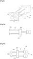
- Such a machine for fiberizing mineral wool by free centrifugation 100 comprises a frame 102 on which the different elements are mounted.
- a plurality of spindles or centrifugation wheels or rotors 104 are arranged in cascade, and capable of rotating around substantially horizontal axes, two successive wheels 104 on the path of the molten material rotating in the opposite direction.
- the first centrifugation wheel 104 is supplied with molten material through a chute and essentially serves to accelerate the material which is returned to the second centrifugation wheel 104 and so on until the last centrifugation wheel, the flow of material decreasing at each centrifugation wheel 104 due to the quantity of fibers formed.
- Such a machine 100 generally further comprises means for generating a current of air (not shown) at the periphery of the centrifugation wheels with the aim of assisting the formation of the fibers by a stretching effect and to take charge of the fibered material by separating it from the infibrated material (shot).
- the air current also has the function of conveying the fiber material to a receiving organ, for example an endless belt equipped with suction boxes, which transports the fibers to the processing devices downstream of the line such as a lapper. , a binder polymerization oven, etc.
- the air current is most often introduced in a direction substantially parallel to the axes of rotation of the centrifugation wheels 104, and thus drives the fibers in a direction perpendicular to their direction of formation.
- the quantity of fibers manufactured depends on the flow rate of material poured onto the centrifuging wheels 104 and on the efficiency of fiberizing by said centrifuging wheels 104.
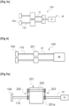
- the centrifugation wheels 104 are connected to a motor block M for their rotation. Each centrifugation wheel 104 is connected to a transmission shaft 110 allowing it to be connected to the motor block M.
- the motor block M comprises, in a first case, a single motor m associated with a gear block N to allow several outputs m' and therefore to rotate several centrifugation wheels 104.
- the motor block M comprises several independent motor m each having an output m'.
- the transmission shafts 110 connecting the centrifuge wheels 104 to the motor block M can be solid or hollow. In the case of a hollow transmission shaft 110, this may include at least one pipe allowing the cooling of the wheels 104 and/or a pipe for bringing binder to the centrifuging wheels 104 for the manufacture of wool. rock.
- the transmission shafts 110 are not geared directly with the engine block M.
- the machine 100 according to the present invention further comprises intermediate transmission means 200 arranged between the engine block M and each shaft transmission 110.
- these intermediate transmission means 200 comprise several intermediate transmission boxes 201, each intermediate transmission box 201 being connected with a transmission shaft 110. It is then understood that, in the case of a single engine m, the intermediate transmission boxes 201 are all connected to the outputs m' of said motor m while for a fiber drawing machine 100 having several motors, each intermediate transmission box 201 is connected to the output m' of a motor m.
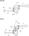
- each intermediate transmission box 201 comprises a chassis 201a in which an axis 202 having a first end and a second end is arranged.
- This 201a chassis can be faired ( figure 5a ) or not ( figure 5b ). These ends are arranged to be outside the fairing chassis or not.
- the axis 202 comprises, at its ends, coupling means 203 for its coupling with the transmission shaft 110 and with the engine block M.
- This intermediate transmission box 201 allows easy assembly and disassembly by simple action on the coupling means 203 to decouple said intermediate transmission box 201 from the engine block M and from the shaft. transmission 110 to which it is coupled.
- it is easy to have access to this intermediate transmission box 201.
- it is easy to dismantle only the wheels centrifuge 104 and the transmission shafts 110 while keeping the intermediate transmission box 201 connected to the engine block M.
- each transmission box 201 comprises a chassis 201a in which two axes 202a, 202b are mounted.
- the axes 202a, 202b are arranged to extend parallel in the same direction.
- the first axis 202a and the second axis 202b are arranged to be mechanically coupled. This coupling is carried out by coupler elements 206.
- the first axis 202a is arranged to be coupled to the motor m while the second axis 202b is arranged to be coupled to the centrifugation wheel 104.
- coupler elements 206 comprise a belt system comprising a pulley on the axis 202a and a pulley on the axis 202b, a belt connecting the two pulleys.
- these coupler elements 206 comprise a chain system comprising a toothed wheel on the axis 202a and a toothed wheel on the axis 202b, a chain connecting the two toothed wheels.
- these coupler elements 206 comprise a gear system comprising a pinion on the axis 202a and a pinion on the axis 202b.
- the gears are meshed with each other directly or indirectly via other gears.
- the first axis 202a and the second axis 202b also each comprise coupling means 203 to be connected, respectively, to the transmission shaft 110 and to the engine block M.
- each transmission box 201 comprises three axes 202a, 202b, 202c.
- the axes 202a, 202b, 202c are arranged to extend parallel in the same direction.
- the first axis 202a is arranged to be mechanically connected with the second axis 202b and the third axis 202c via coupler elements 206.
- Coupling means 203 are arranged to connect the transmission box 201 to the transmission shaft 110 and to the motor block M.
- the second axis 202b is coupled to the motor block M and the third axis 202c is coupled to the transmission shaft 110.
- coupler elements 206 allow the coupling of the first axis 202a with the second axis 202b to be different from the coupler elements 206 allow the coupling of the first axis 202a with the third axis 202c.
- the advantage of the second mode of execution and the third mode of execution is to allow the presence of standard coupling means 203 while allowing an increase in the rotation speed.
- the presence of the coupler elements 206 authorizes the presence of a reduction between the axes 202a, 202b, 202c to increase the rotation speed of the centrifugation wheel 104 relative to the rotation speed of the motor.
- the coupling means 203 may comprise a belt system comprising a pulley 2031 on the axis 202 and a pulley 2031 on the transmission shaft 110 or on an output m' of the engine block .
- a belt 2032 connects the two pulleys 2031 as visible in the figure 8a .
- these coupling means 203 may comprise a chain system comprising a toothed wheel 2033 on the axis 202 and a toothed wheel 2033 on the transmission shaft 110 or on an output m' of the engine block.
- a chain or toothed belt 2034 connects the two toothed wheels as visible in the figure 8b .
- these coupling means 203 may comprise a gear system comprising a pinion 2035 on the axis 202 and a pinion 2035 on the transmission shaft 110 or on an output m' of the engine block M.
- the pinions 2035 are meshed l 'with each other directly or indirectly via other gears 2035 as visible at figure 8c .
- the shaft 110 can be in direct contact with the axis 202 of the intermediate transmission box 200 via screws or teeth extending in the same direction as the axis.
- the coupling means 203 are, optionally, arranged to allow a reduction increasing the speed of the centrifugation wheel 104 relative to the speed of the motor m.
- This intermediate transmission box 201 also has the advantage of allowing the centrifugation wheel 104 not to be in the axis of the motor axis m'. Thus, it is possible to position the centrifugation wheels 104 as desired.
- the fiberizing machine 100 comprises intermediate transmission means 200 arranged so that all of the transmission shafts 110 are connected thereto.
- the intermediate transmission means 200 comprise a single intermediate transmission box 210.
- this single intermediate transmission box 210 comprises a chassis 210a in which a plurality of axes 212 is arranged.
- the number of axes 212 is equal to the number of wheels 104.
- each axis 212 comprises coupling means 203 for being coupled to the motor block M and to the centrifugation wheels 104 as visible in the figures 10, 11 And 14 .
- each axis 212 is replaced by two axes 212a, 212b arranged to extend parallel in the same direction.
- the first axis 212a and the second axis 212b are arranged to be mechanically coupled by coupler elements 206.
- the first axis 212a is arranged to be coupled to the motor m while the second axis 212b is arranged to be coupled to the centrifugation wheel 104 .
- each transmission box 210 comprises three axes 212a, 212b, 212c.
- the axes 212a, 212b, 212c are arranged to extend parallel in the same direction.
- the first axis 212a is arranged to be mechanically with the second axis 212b and the third axis 212c via coupler elements 206.
- the second axis 212b is coupled to the engine block M by coupling means 203.
- the third axis 212c is coupled to the transmission shaft 110 by coupling means 203.
- the coupling means 203 coupling the transmission shaft 110 to the transmission box 210 are simply a bolting of said shaft 110 to the axis 212c of the transmission box 210.
- the coupling means 203 may comprise a belt system comprising a pulley on the axis 202 and a pulley on the transmission shaft 110 or on an outlet m' of the engine block.
- a belt connects the two pulleys.
- these coupling means 203 can comprise a chain system comprising a toothed wheel on the axis 202 and a toothed wheel on the transmission shaft 110 or on an output m' of the engine block.
- a chain connects the two toothed wheels.
- these coupling means 203 may comprise a gear system comprising a pinion on the axis 202 and a pinion on the transmission shaft 110 or on an output m' of the engine block M.
- the pinions are meshed with one another the other directly or indirectly via other gears.
- the shaft 110 can be in direct contact with the axis of the intermediate transmission box 200 via screws or teeth extending in the same direction as the axis.
- the coupling means 203 or the coupler elements 206 are arranged to allow the speed to be modified between an input axis, connected directly or indirectly to the motor block M, and an axis output connected directly or indirectly to the centrifugation wheel 104.
- This variation in the rotation speed is obtained by modifying the gear or the pulleys or the toothed wheels forming coupling elements 206 and/or the coupling means 203 to obtain a multiplication.
- the pulley of the output axis will be of smaller diameter than that of the input axis.
- the toothed wheel of the output axis will be of smaller diameter and will have fewer teeth than that of the axis entry.
- the pinion of the output axis will be of smaller diameter and will have less teeth than that of the input axis.
- This variant advantageously makes it possible to increase the rotation speed of the rotors/centrifuging wheels 104 without requiring a more efficient motor block M. It becomes easy to modify the coupling means 203 or the coupler elements 206 to adapt to the desired rotation speed.
- intermediate transmission boxes 210 with identical coupling means 203 advantageously makes it possible to standardize these parts which tend to wear out. Consequently, this standardization provides an advantage in terms of maintenance because there is only one model of intermediate gearbox 210.
- the transmission shaft 110 is composed of two half-shafts. These half-shafts are connected to each other by coupling elements which may be a belt associated with two pulleys or a chain associated with two toothed wheels or two pinions meshing with each other. A first half-shaft is connected to the intermediate transmission box while the second half-shaft is connected to the centrifugal wheel 104 used for fiber drawing.
- the coupling elements are designed so that the second half shaft connected to the centrifugation wheel 104 has a rotation speed greater than the rotation speed of the first half shaft connected to the intermediate transmission box 201, 210.
Landscapes
- Engineering & Computer Science (AREA)
- Chemical & Material Sciences (AREA)
- Materials Engineering (AREA)
- Geochemistry & Mineralogy (AREA)
- Manufacturing & Machinery (AREA)
- General Life Sciences & Earth Sciences (AREA)
- Life Sciences & Earth Sciences (AREA)
- Organic Chemistry (AREA)
- Mechanical Engineering (AREA)
- Textile Engineering (AREA)
- Centrifugal Separators (AREA)
- Arrangement Of Transmissions (AREA)
- Manufacture, Treatment Of Glass Fibers (AREA)
- Preliminary Treatment Of Fibers (AREA)
- Transmission Devices (AREA)
Applications Claiming Priority (2)
| Application Number | Priority Date | Filing Date | Title |
|---|---|---|---|
| FR1873401A FR3090619B1 (fr) | 2018-12-19 | 2018-12-19 | Machine de fibrage à maintenance améliorée |
| PCT/FR2019/053103 WO2020128287A1 (fr) | 2018-12-19 | 2019-12-17 | Machine de fibrage a maintenance améliorée |
Publications (3)
| Publication Number | Publication Date |
|---|---|
| EP3898536A1 EP3898536A1 (fr) | 2021-10-27 |
| EP3898536C0 EP3898536C0 (fr) | 2023-10-18 |
| EP3898536B1 true EP3898536B1 (fr) | 2023-10-18 |
Family
ID=66542414
Family Applications (1)
| Application Number | Title | Priority Date | Filing Date |
|---|---|---|---|
| EP19842828.6A Active EP3898536B1 (fr) | 2018-12-19 | 2019-12-17 | Machine de fibrage a maintenance améliorée |
Country Status (6)
| Country | Link |
|---|---|
| US (2) | US12404203B2 (pl) |
| EP (1) | EP3898536B1 (pl) |
| FR (1) | FR3090619B1 (pl) |
| PL (1) | PL3898536T3 (pl) |
| RU (1) | RU2765359C1 (pl) |
| WO (1) | WO2020128287A1 (pl) |
Families Citing this family (1)
| Publication number | Priority date | Publication date | Assignee | Title |
|---|---|---|---|---|
| CN113666629A (zh) * | 2021-09-17 | 2021-11-19 | 移动源保温材料(河南)有限公司 | 可调节玄武岩纤维直径的生产控制装置 |
Family Cites Families (7)
| Publication number | Priority date | Publication date | Assignee | Title |
|---|---|---|---|---|
| US2398707A (en) * | 1943-04-29 | 1946-04-16 | Johns Manville | Fiberizing apparatus |
| US3191452A (en) * | 1964-03-17 | 1965-06-29 | Lipski Mitchell | Power transmission apparatus |
| SU744326A1 (ru) * | 1977-12-05 | 1980-06-30 | Всесоюзный Научно-Исследовательский И Проектный Институт "Теплопроект" | Устройство дл исследовани процесса волокнообразовани |
| FR2657077B1 (fr) * | 1990-01-16 | 1993-07-02 | Saint Gobain Isover | Procede et dispositif de fibrage de laine minerale par centrifugation libre. |
| JP3083684B2 (ja) * | 1993-06-29 | 2000-09-04 | 富士写真フイルム株式会社 | ベルト伝動機構 |
| CN2608498Y (zh) * | 2003-03-24 | 2004-03-31 | 吉林市智能自动化工程有限责任公司 | 甩丝机 |
| RU2365541C1 (ru) * | 2008-05-04 | 2009-08-27 | Государственное образовательное учреждение высшего профессионального образования "Южно-Уральский государственный университет" | Многовалковая центрифуга для получения минеральной ваты |
-
2018
- 2018-12-19 FR FR1873401A patent/FR3090619B1/fr active Active
-
2019
- 2019-12-17 PL PL19842828.6T patent/PL3898536T3/pl unknown
- 2019-12-17 EP EP19842828.6A patent/EP3898536B1/fr active Active
- 2019-12-17 US US17/416,241 patent/US12404203B2/en active Active
- 2019-12-17 WO PCT/FR2019/053103 patent/WO2020128287A1/fr not_active Ceased
- 2019-12-17 RU RU2021120317A patent/RU2765359C1/ru active
-
2025
- 2025-08-06 US US19/292,145 patent/US20250361169A1/en active Pending
Also Published As
| Publication number | Publication date |
|---|---|
| PL3898536T3 (pl) | 2024-02-12 |
| EP3898536A1 (fr) | 2021-10-27 |
| FR3090619A1 (fr) | 2020-06-26 |
| FR3090619B1 (fr) | 2021-01-01 |
| WO2020128287A1 (fr) | 2020-06-25 |
| EP3898536C0 (fr) | 2023-10-18 |
| US12404203B2 (en) | 2025-09-02 |
| RU2765359C1 (ru) | 2022-01-28 |
| US20250361169A1 (en) | 2025-11-27 |
| US20220055940A1 (en) | 2022-02-24 |
Similar Documents
| Publication | Publication Date | Title |
|---|---|---|
| EP2638966A1 (fr) | Dispositif d'entraînement et broyeur correspondant | |
| FR3035944A1 (fr) | Transmission et dispositif d'entrainement equipe de celle-ci | |
| FR2708068A1 (fr) | Transmission à friction continûment variable. | |
| EP3898536B1 (fr) | Machine de fibrage a maintenance améliorée | |
| FR3042009A1 (fr) | Turbo moteur a soufflantes deportees avec un systeme differentiel | |
| EP3176019B1 (fr) | Groupe motopropulseur d'un vehicule | |
| JP5858546B2 (ja) | スクリュー遠心分離機の駆動装置 | |
| JP2013537102A5 (pl) | ||
| FR3016408A1 (fr) | Ensemble d'entrainement d'accessoires pour turbomachine d'aeronef | |
| WO2016066919A1 (fr) | Capot de récupération d'huile de lubrification pour un équipement de turbomachine | |
| CH628963A5 (fr) | Transmission par engrenages a trains partages. | |
| FR2994585A1 (fr) | Boite d'engrenages a encombrement reduit pour turbomachine d'aeronef | |
| WO2016087434A1 (fr) | Dispositif de transmission de vitesse pour le déplacement d'un véhicule automobile, notamment d'un véhicule motorisé à au moins deux roues, et groupe motopropulseur utilisant un tel dispositif en particulier pour un véhicule hybride | |
| EP2534389B1 (fr) | Dispositif d'accouplement entre un arbre et une poulie et bloc moteur pouvant equiper un vehicule automobile | |
| EP2159439B1 (fr) | Dispositif de friction pour transmission de couple | |
| EP3274610B1 (fr) | Boîte à engrenages comportant un réducteur amélioré | |
| FR2584103A1 (fr) | Dispositif de defibrage de vegetaux fibreux | |
| WO1997029304A1 (fr) | Transmission automatique a variation continue depuis un rapport infini jusqu'au rapport 1/1 | |
| EP1147329B1 (fr) | Transmission mecanique a variation continue du rapport de transmission | |
| FR3044092A1 (fr) | Banc d'essais pour paliers simulant un effet centrifuge | |
| WO1987004764A1 (fr) | Dispositif a changement continu de vitesse | |
| FR3148462A1 (fr) | Système d’entraînement d’accessoires comprenant un embrayage à disques et une machine électrique génératrice. | |
| EP3901422A1 (fr) | Pignon avec un dispositif de lubrification | |
| EP2385265A1 (fr) | Dispositif d'accouplement entre un arbre et une poulie et bloc moteur pouvant équiper un véhicule automobile et comprenant le dispositif d'accouplement | |
| FR3051874A3 (fr) | Boite de vitesses pour vehicule automobile pourvue d'un systeme de lubrification forcee |
Legal Events
| Date | Code | Title | Description |
|---|---|---|---|
| STAA | Information on the status of an ep patent application or granted ep patent |
Free format text: STATUS: UNKNOWN |
|
| STAA | Information on the status of an ep patent application or granted ep patent |
Free format text: STATUS: THE INTERNATIONAL PUBLICATION HAS BEEN MADE |
|
| PUAI | Public reference made under article 153(3) epc to a published international application that has entered the european phase |
Free format text: ORIGINAL CODE: 0009012 |
|
| STAA | Information on the status of an ep patent application or granted ep patent |
Free format text: STATUS: REQUEST FOR EXAMINATION WAS MADE |
|
| 17P | Request for examination filed |
Effective date: 20210719 |
|
| AK | Designated contracting states |
Kind code of ref document: A1 Designated state(s): AL AT BE BG CH CY CZ DE DK EE ES FI FR GB GR HR HU IE IS IT LI LT LU LV MC MK MT NL NO PL PT RO RS SE SI SK SM TR |
|
| DAV | Request for validation of the european patent (deleted) | ||
| DAX | Request for extension of the european patent (deleted) | ||
| STAA | Information on the status of an ep patent application or granted ep patent |
Free format text: STATUS: EXAMINATION IS IN PROGRESS |
|
| 17Q | First examination report despatched |
Effective date: 20220525 |
|
| GRAP | Despatch of communication of intention to grant a patent |
Free format text: ORIGINAL CODE: EPIDOSNIGR1 |
|
| STAA | Information on the status of an ep patent application or granted ep patent |
Free format text: STATUS: GRANT OF PATENT IS INTENDED |
|
| INTG | Intention to grant announced |
Effective date: 20230510 |
|
| RIN1 | Information on inventor provided before grant (corrected) |
Inventor name: MORIN, PHILIPPE Inventor name: JANKOVSKY, JIRI |
|
| P01 | Opt-out of the competence of the unified patent court (upc) registered |
Effective date: 20230421 |
|
| GRAS | Grant fee paid |
Free format text: ORIGINAL CODE: EPIDOSNIGR3 |
|
| GRAA | (expected) grant |
Free format text: ORIGINAL CODE: 0009210 |
|
| STAA | Information on the status of an ep patent application or granted ep patent |
Free format text: STATUS: THE PATENT HAS BEEN GRANTED |
|
| AK | Designated contracting states |
Kind code of ref document: B1 Designated state(s): AL AT BE BG CH CY CZ DE DK EE ES FI FR GB GR HR HU IE IS IT LI LT LU LV MC MK MT NL NO PL PT RO RS SE SI SK SM TR |
|
| REG | Reference to a national code |
Ref country code: GB Ref legal event code: FG4D Free format text: NOT ENGLISH |
|
| REG | Reference to a national code |
Ref country code: CH Ref legal event code: EP |
|
| REG | Reference to a national code |
Ref country code: IE Ref legal event code: FG4D Free format text: LANGUAGE OF EP DOCUMENT: FRENCH |
|
| REG | Reference to a national code |
Ref country code: DE Ref legal event code: R096 Ref document number: 602019039780 Country of ref document: DE |
|
| P04 | Withdrawal of opt-out of the competence of the unified patent court (upc) registered |
Effective date: 20231103 |
|
| U01 | Request for unitary effect filed |
Effective date: 20231102 |
|
| U07 | Unitary effect registered |
Designated state(s): AT BE BG DE DK EE FI FR IT LT LU LV MT NL PT SE SI Effective date: 20231108 |
|
| U20 | Renewal fee for the european patent with unitary effect paid |
Year of fee payment: 5 Effective date: 20240208 |
|
| PG25 | Lapsed in a contracting state [announced via postgrant information from national office to epo] |
Ref country code: GR Free format text: LAPSE BECAUSE OF FAILURE TO SUBMIT A TRANSLATION OF THE DESCRIPTION OR TO PAY THE FEE WITHIN THE PRESCRIBED TIME-LIMIT Effective date: 20240119 |
|
| PG25 | Lapsed in a contracting state [announced via postgrant information from national office to epo] |
Ref country code: IS Free format text: LAPSE BECAUSE OF FAILURE TO SUBMIT A TRANSLATION OF THE DESCRIPTION OR TO PAY THE FEE WITHIN THE PRESCRIBED TIME-LIMIT Effective date: 20240218 |
|
| PG25 | Lapsed in a contracting state [announced via postgrant information from national office to epo] |
Ref country code: ES Free format text: LAPSE BECAUSE OF FAILURE TO SUBMIT A TRANSLATION OF THE DESCRIPTION OR TO PAY THE FEE WITHIN THE PRESCRIBED TIME-LIMIT Effective date: 20231018 |
|
| PG25 | Lapsed in a contracting state [announced via postgrant information from national office to epo] |
Ref country code: IS Free format text: LAPSE BECAUSE OF FAILURE TO SUBMIT A TRANSLATION OF THE DESCRIPTION OR TO PAY THE FEE WITHIN THE PRESCRIBED TIME-LIMIT Effective date: 20240218 Ref country code: GR Free format text: LAPSE BECAUSE OF FAILURE TO SUBMIT A TRANSLATION OF THE DESCRIPTION OR TO PAY THE FEE WITHIN THE PRESCRIBED TIME-LIMIT Effective date: 20240119 Ref country code: ES Free format text: LAPSE BECAUSE OF FAILURE TO SUBMIT A TRANSLATION OF THE DESCRIPTION OR TO PAY THE FEE WITHIN THE PRESCRIBED TIME-LIMIT Effective date: 20231018 |
|
| PG25 | Lapsed in a contracting state [announced via postgrant information from national office to epo] |
Ref country code: RS Free format text: LAPSE BECAUSE OF FAILURE TO SUBMIT A TRANSLATION OF THE DESCRIPTION OR TO PAY THE FEE WITHIN THE PRESCRIBED TIME-LIMIT Effective date: 20231018 Ref country code: NO Free format text: LAPSE BECAUSE OF FAILURE TO SUBMIT A TRANSLATION OF THE DESCRIPTION OR TO PAY THE FEE WITHIN THE PRESCRIBED TIME-LIMIT Effective date: 20240118 Ref country code: HR Free format text: LAPSE BECAUSE OF FAILURE TO SUBMIT A TRANSLATION OF THE DESCRIPTION OR TO PAY THE FEE WITHIN THE PRESCRIBED TIME-LIMIT Effective date: 20231018 |
|
| REG | Reference to a national code |
Ref country code: DE Ref legal event code: R097 Ref document number: 602019039780 Country of ref document: DE |
|
| PG25 | Lapsed in a contracting state [announced via postgrant information from national office to epo] |
Ref country code: CZ Free format text: LAPSE BECAUSE OF FAILURE TO SUBMIT A TRANSLATION OF THE DESCRIPTION OR TO PAY THE FEE WITHIN THE PRESCRIBED TIME-LIMIT Effective date: 20231018 |
|
| PG25 | Lapsed in a contracting state [announced via postgrant information from national office to epo] |
Ref country code: SK Free format text: LAPSE BECAUSE OF FAILURE TO SUBMIT A TRANSLATION OF THE DESCRIPTION OR TO PAY THE FEE WITHIN THE PRESCRIBED TIME-LIMIT Effective date: 20231018 |
|
| PG25 | Lapsed in a contracting state [announced via postgrant information from national office to epo] |
Ref country code: SM Free format text: LAPSE BECAUSE OF FAILURE TO SUBMIT A TRANSLATION OF THE DESCRIPTION OR TO PAY THE FEE WITHIN THE PRESCRIBED TIME-LIMIT Effective date: 20231018 Ref country code: SK Free format text: LAPSE BECAUSE OF FAILURE TO SUBMIT A TRANSLATION OF THE DESCRIPTION OR TO PAY THE FEE WITHIN THE PRESCRIBED TIME-LIMIT Effective date: 20231018 Ref country code: RO Free format text: LAPSE BECAUSE OF FAILURE TO SUBMIT A TRANSLATION OF THE DESCRIPTION OR TO PAY THE FEE WITHIN THE PRESCRIBED TIME-LIMIT Effective date: 20231018 Ref country code: CZ Free format text: LAPSE BECAUSE OF FAILURE TO SUBMIT A TRANSLATION OF THE DESCRIPTION OR TO PAY THE FEE WITHIN THE PRESCRIBED TIME-LIMIT Effective date: 20231018 |
|
| REG | Reference to a national code |
Ref country code: CH Ref legal event code: PL |
|
| PLBE | No opposition filed within time limit |
Free format text: ORIGINAL CODE: 0009261 |
|
| STAA | Information on the status of an ep patent application or granted ep patent |
Free format text: STATUS: NO OPPOSITION FILED WITHIN TIME LIMIT |
|
| PG25 | Lapsed in a contracting state [announced via postgrant information from national office to epo] |
Ref country code: MC Free format text: LAPSE BECAUSE OF FAILURE TO SUBMIT A TRANSLATION OF THE DESCRIPTION OR TO PAY THE FEE WITHIN THE PRESCRIBED TIME-LIMIT Effective date: 20231018 |
|
| PG25 | Lapsed in a contracting state [announced via postgrant information from national office to epo] |
Ref country code: MC Free format text: LAPSE BECAUSE OF FAILURE TO SUBMIT A TRANSLATION OF THE DESCRIPTION OR TO PAY THE FEE WITHIN THE PRESCRIBED TIME-LIMIT Effective date: 20231018 |
|
| 26N | No opposition filed |
Effective date: 20240719 |
|
| GBPC | Gb: european patent ceased through non-payment of renewal fee |
Effective date: 20240118 |
|
| REG | Reference to a national code |
Ref country code: IE Ref legal event code: MM4A |
|
| PG25 | Lapsed in a contracting state [announced via postgrant information from national office to epo] |
Ref country code: IE Free format text: LAPSE BECAUSE OF NON-PAYMENT OF DUE FEES Effective date: 20231217 |
|
| PG25 | Lapsed in a contracting state [announced via postgrant information from national office to epo] |
Ref country code: GB Free format text: LAPSE BECAUSE OF NON-PAYMENT OF DUE FEES Effective date: 20240118 |
|
| PG25 | Lapsed in a contracting state [announced via postgrant information from national office to epo] |
Ref country code: CH Free format text: LAPSE BECAUSE OF NON-PAYMENT OF DUE FEES Effective date: 20231231 |
|
| PG25 | Lapsed in a contracting state [announced via postgrant information from national office to epo] |
Ref country code: IE Free format text: LAPSE BECAUSE OF NON-PAYMENT OF DUE FEES Effective date: 20231217 Ref country code: GB Free format text: LAPSE BECAUSE OF NON-PAYMENT OF DUE FEES Effective date: 20240118 Ref country code: CH Free format text: LAPSE BECAUSE OF NON-PAYMENT OF DUE FEES Effective date: 20231231 |
|
| U1N | Appointed representative for the unitary patent procedure changed after the registration of the unitary effect |
Representative=s name: SAINT-GOBAIN RECHERCHE; FR |
|
| U20 | Renewal fee for the european patent with unitary effect paid |
Year of fee payment: 6 Effective date: 20241107 |
|
| P05 | Withdrawal of opt-out of the competence of the unified patent court (upc) changed |
Free format text: CASE NUMBER: APP_585224/2023 Effective date: 20231108 |
|
| PG25 | Lapsed in a contracting state [announced via postgrant information from national office to epo] |
Ref country code: CY Free format text: LAPSE BECAUSE OF FAILURE TO SUBMIT A TRANSLATION OF THE DESCRIPTION OR TO PAY THE FEE WITHIN THE PRESCRIBED TIME-LIMIT; INVALID AB INITIO Effective date: 20191217 |
|
| PG25 | Lapsed in a contracting state [announced via postgrant information from national office to epo] |
Ref country code: HU Free format text: LAPSE BECAUSE OF FAILURE TO SUBMIT A TRANSLATION OF THE DESCRIPTION OR TO PAY THE FEE WITHIN THE PRESCRIBED TIME-LIMIT; INVALID AB INITIO Effective date: 20191217 |
|
| PG25 | Lapsed in a contracting state [announced via postgrant information from national office to epo] |
Ref country code: TR Free format text: LAPSE BECAUSE OF FAILURE TO SUBMIT A TRANSLATION OF THE DESCRIPTION OR TO PAY THE FEE WITHIN THE PRESCRIBED TIME-LIMIT Effective date: 20231018 |
|
| U20 | Renewal fee for the european patent with unitary effect paid |
Year of fee payment: 7 Effective date: 20251110 |
|
| PGFP | Annual fee paid to national office [announced via postgrant information from national office to epo] |
Ref country code: PL Payment date: 20251105 Year of fee payment: 7 |