EP3898181B1 - Parallelisierte 3d-lithographie mittels mehrstrahliger, mehrfarbiger lichtinduzierter polymerisation - Google Patents
Parallelisierte 3d-lithographie mittels mehrstrahliger, mehrfarbiger lichtinduzierter polymerisation Download PDFInfo
- Publication number
- EP3898181B1 EP3898181B1 EP19797585.7A EP19797585A EP3898181B1 EP 3898181 B1 EP3898181 B1 EP 3898181B1 EP 19797585 A EP19797585 A EP 19797585A EP 3898181 B1 EP3898181 B1 EP 3898181B1
- Authority
- EP
- European Patent Office
- Prior art keywords
- light source
- wavelength
- photoresist
- photon
- laser
- Prior art date
- Legal status (The legal status is an assumption and is not a legal conclusion. Google has not performed a legal analysis and makes no representation as to the accuracy of the status listed.)
- Active
Links
Images

Classifications
-
- B—PERFORMING OPERATIONS; TRANSPORTING
- B29—WORKING OF PLASTICS; WORKING OF SUBSTANCES IN A PLASTIC STATE IN GENERAL
- B29C—SHAPING OR JOINING OF PLASTICS; SHAPING OF MATERIAL IN A PLASTIC STATE, NOT OTHERWISE PROVIDED FOR; AFTER-TREATMENT OF THE SHAPED PRODUCTS, e.g. REPAIRING
- B29C64/00—Additive manufacturing, i.e. manufacturing of three-dimensional [3D] objects by additive deposition, additive agglomeration or additive layering, e.g. by 3D printing, stereolithography or selective laser sintering
- B29C64/10—Processes of additive manufacturing
- B29C64/106—Processes of additive manufacturing using only liquids or viscous materials, e.g. depositing a continuous bead of viscous material
- B29C64/124—Processes of additive manufacturing using only liquids or viscous materials, e.g. depositing a continuous bead of viscous material using layers of liquid which are selectively solidified
- B29C64/129—Processes of additive manufacturing using only liquids or viscous materials, e.g. depositing a continuous bead of viscous material using layers of liquid which are selectively solidified characterised by the energy source therefor, e.g. by global irradiation combined with a mask
-
- B—PERFORMING OPERATIONS; TRANSPORTING
- B29—WORKING OF PLASTICS; WORKING OF SUBSTANCES IN A PLASTIC STATE IN GENERAL
- B29C—SHAPING OR JOINING OF PLASTICS; SHAPING OF MATERIAL IN A PLASTIC STATE, NOT OTHERWISE PROVIDED FOR; AFTER-TREATMENT OF THE SHAPED PRODUCTS, e.g. REPAIRING
- B29C64/00—Additive manufacturing, i.e. manufacturing of three-dimensional [3D] objects by additive deposition, additive agglomeration or additive layering, e.g. by 3D printing, stereolithography or selective laser sintering
- B29C64/10—Processes of additive manufacturing
- B29C64/106—Processes of additive manufacturing using only liquids or viscous materials, e.g. depositing a continuous bead of viscous material
- B29C64/124—Processes of additive manufacturing using only liquids or viscous materials, e.g. depositing a continuous bead of viscous material using layers of liquid which are selectively solidified
-
- B—PERFORMING OPERATIONS; TRANSPORTING
- B29—WORKING OF PLASTICS; WORKING OF SUBSTANCES IN A PLASTIC STATE IN GENERAL
- B29C—SHAPING OR JOINING OF PLASTICS; SHAPING OF MATERIAL IN A PLASTIC STATE, NOT OTHERWISE PROVIDED FOR; AFTER-TREATMENT OF THE SHAPED PRODUCTS, e.g. REPAIRING
- B29C64/00—Additive manufacturing, i.e. manufacturing of three-dimensional [3D] objects by additive deposition, additive agglomeration or additive layering, e.g. by 3D printing, stereolithography or selective laser sintering
- B29C64/20—Apparatus for additive manufacturing; Details thereof or accessories therefor
- B29C64/245—Platforms or substrates
-
- B—PERFORMING OPERATIONS; TRANSPORTING
- B29—WORKING OF PLASTICS; WORKING OF SUBSTANCES IN A PLASTIC STATE IN GENERAL
- B29C—SHAPING OR JOINING OF PLASTICS; SHAPING OF MATERIAL IN A PLASTIC STATE, NOT OTHERWISE PROVIDED FOR; AFTER-TREATMENT OF THE SHAPED PRODUCTS, e.g. REPAIRING
- B29C64/00—Additive manufacturing, i.e. manufacturing of three-dimensional [3D] objects by additive deposition, additive agglomeration or additive layering, e.g. by 3D printing, stereolithography or selective laser sintering
- B29C64/20—Apparatus for additive manufacturing; Details thereof or accessories therefor
- B29C64/255—Enclosures for the building material, e.g. powder containers
-
- B—PERFORMING OPERATIONS; TRANSPORTING
- B29—WORKING OF PLASTICS; WORKING OF SUBSTANCES IN A PLASTIC STATE IN GENERAL
- B29C—SHAPING OR JOINING OF PLASTICS; SHAPING OF MATERIAL IN A PLASTIC STATE, NOT OTHERWISE PROVIDED FOR; AFTER-TREATMENT OF THE SHAPED PRODUCTS, e.g. REPAIRING
- B29C64/00—Additive manufacturing, i.e. manufacturing of three-dimensional [3D] objects by additive deposition, additive agglomeration or additive layering, e.g. by 3D printing, stereolithography or selective laser sintering
- B29C64/20—Apparatus for additive manufacturing; Details thereof or accessories therefor
- B29C64/264—Arrangements for irradiation
- B29C64/268—Arrangements for irradiation using laser beams; using electron beams [EB]
- B29C64/273—Arrangements for irradiation using laser beams; using electron beams [EB] pulsed; frequency modulated
-
- B—PERFORMING OPERATIONS; TRANSPORTING
- B29—WORKING OF PLASTICS; WORKING OF SUBSTANCES IN A PLASTIC STATE IN GENERAL
- B29C—SHAPING OR JOINING OF PLASTICS; SHAPING OF MATERIAL IN A PLASTIC STATE, NOT OTHERWISE PROVIDED FOR; AFTER-TREATMENT OF THE SHAPED PRODUCTS, e.g. REPAIRING
- B29C64/00—Additive manufacturing, i.e. manufacturing of three-dimensional [3D] objects by additive deposition, additive agglomeration or additive layering, e.g. by 3D printing, stereolithography or selective laser sintering
- B29C64/20—Apparatus for additive manufacturing; Details thereof or accessories therefor
- B29C64/264—Arrangements for irradiation
- B29C64/277—Arrangements for irradiation using multiple radiation means, e.g. micromirrors or multiple light-emitting diodes [LED]
- B29C64/282—Arrangements for irradiation using multiple radiation means, e.g. micromirrors or multiple light-emitting diodes [LED] of the same type, e.g. using different energy levels
-
- B—PERFORMING OPERATIONS; TRANSPORTING
- B33—ADDITIVE MANUFACTURING TECHNOLOGY
- B33Y—ADDITIVE MANUFACTURING, i.e. MANUFACTURING OF THREE-DIMENSIONAL [3D] OBJECTS BY ADDITIVE DEPOSITION, ADDITIVE AGGLOMERATION OR ADDITIVE LAYERING, e.g. BY 3D PRINTING, STEREOLITHOGRAPHY OR SELECTIVE LASER SINTERING
- B33Y10/00—Processes of additive manufacturing
-
- B—PERFORMING OPERATIONS; TRANSPORTING
- B33—ADDITIVE MANUFACTURING TECHNOLOGY
- B33Y—ADDITIVE MANUFACTURING, i.e. MANUFACTURING OF THREE-DIMENSIONAL [3D] OBJECTS BY ADDITIVE DEPOSITION, ADDITIVE AGGLOMERATION OR ADDITIVE LAYERING, e.g. BY 3D PRINTING, STEREOLITHOGRAPHY OR SELECTIVE LASER SINTERING
- B33Y30/00—Apparatus for additive manufacturing; Details thereof or accessories therefor
-
- B—PERFORMING OPERATIONS; TRANSPORTING
- B33—ADDITIVE MANUFACTURING TECHNOLOGY
- B33Y—ADDITIVE MANUFACTURING, i.e. MANUFACTURING OF THREE-DIMENSIONAL [3D] OBJECTS BY ADDITIVE DEPOSITION, ADDITIVE AGGLOMERATION OR ADDITIVE LAYERING, e.g. BY 3D PRINTING, STEREOLITHOGRAPHY OR SELECTIVE LASER SINTERING
- B33Y70/00—Materials specially adapted for additive manufacturing
-
- G—PHYSICS
- G03—PHOTOGRAPHY; CINEMATOGRAPHY; ANALOGOUS TECHNIQUES USING WAVES OTHER THAN OPTICAL WAVES; ELECTROGRAPHY; HOLOGRAPHY
- G03F—PHOTOMECHANICAL PRODUCTION OF TEXTURED OR PATTERNED SURFACES, e.g. FOR PRINTING, FOR PROCESSING OF SEMICONDUCTOR DEVICES; MATERIALS THEREFOR; ORIGINALS THEREFOR; APPARATUS SPECIALLY ADAPTED THEREFOR
- G03F7/00—Photomechanical, e.g. photolithographic, production of textured or patterned surfaces, e.g. printing surfaces; Materials therefor, e.g. comprising photoresists; Apparatus specially adapted therefor
- G03F7/0037—Production of three-dimensional images
-
- G—PHYSICS
- G03—PHOTOGRAPHY; CINEMATOGRAPHY; ANALOGOUS TECHNIQUES USING WAVES OTHER THAN OPTICAL WAVES; ELECTROGRAPHY; HOLOGRAPHY
- G03F—PHOTOMECHANICAL PRODUCTION OF TEXTURED OR PATTERNED SURFACES, e.g. FOR PRINTING, FOR PROCESSING OF SEMICONDUCTOR DEVICES; MATERIALS THEREFOR; ORIGINALS THEREFOR; APPARATUS SPECIALLY ADAPTED THEREFOR
- G03F7/00—Photomechanical, e.g. photolithographic, production of textured or patterned surfaces, e.g. printing surfaces; Materials therefor, e.g. comprising photoresists; Apparatus specially adapted therefor
- G03F7/004—Photosensitive materials
- G03F7/027—Non-macromolecular photopolymerisable compounds having carbon-to-carbon double bonds, e.g. ethylenic compounds
- G03F7/028—Non-macromolecular photopolymerisable compounds having carbon-to-carbon double bonds, e.g. ethylenic compounds with photosensitivity-increasing substances, e.g. photoinitiators
- G03F7/031—Organic compounds not covered by group G03F7/029
-
- G—PHYSICS
- G03—PHOTOGRAPHY; CINEMATOGRAPHY; ANALOGOUS TECHNIQUES USING WAVES OTHER THAN OPTICAL WAVES; ELECTROGRAPHY; HOLOGRAPHY
- G03F—PHOTOMECHANICAL PRODUCTION OF TEXTURED OR PATTERNED SURFACES, e.g. FOR PRINTING, FOR PROCESSING OF SEMICONDUCTOR DEVICES; MATERIALS THEREFOR; ORIGINALS THEREFOR; APPARATUS SPECIALLY ADAPTED THEREFOR
- G03F7/00—Photomechanical, e.g. photolithographic, production of textured or patterned surfaces, e.g. printing surfaces; Materials therefor, e.g. comprising photoresists; Apparatus specially adapted therefor
- G03F7/004—Photosensitive materials
- G03F7/09—Photosensitive materials characterised by structural details, e.g. supports, auxiliary layers
- G03F7/095—Photosensitive materials characterised by structural details, e.g. supports, auxiliary layers having more than one photosensitive layer
-
- G—PHYSICS
- G03—PHOTOGRAPHY; CINEMATOGRAPHY; ANALOGOUS TECHNIQUES USING WAVES OTHER THAN OPTICAL WAVES; ELECTROGRAPHY; HOLOGRAPHY
- G03F—PHOTOMECHANICAL PRODUCTION OF TEXTURED OR PATTERNED SURFACES, e.g. FOR PRINTING, FOR PROCESSING OF SEMICONDUCTOR DEVICES; MATERIALS THEREFOR; ORIGINALS THEREFOR; APPARATUS SPECIALLY ADAPTED THEREFOR
- G03F7/00—Photomechanical, e.g. photolithographic, production of textured or patterned surfaces, e.g. printing surfaces; Materials therefor, e.g. comprising photoresists; Apparatus specially adapted therefor
- G03F7/20—Exposure; Apparatus therefor
- G03F7/2002—Exposure; Apparatus therefor with visible light or UV light, through an original having an opaque pattern on a transparent support, e.g. film printing, projection printing; by reflection of visible or UV light from an original such as a printed image
- G03F7/2012—Exposure; Apparatus therefor with visible light or UV light, through an original having an opaque pattern on a transparent support, e.g. film printing, projection printing; by reflection of visible or UV light from an original such as a printed image using liquid photohardening compositions, e.g. for the production of reliefs such as flexographic plates or stamps
-
- G—PHYSICS
- G03—PHOTOGRAPHY; CINEMATOGRAPHY; ANALOGOUS TECHNIQUES USING WAVES OTHER THAN OPTICAL WAVES; ELECTROGRAPHY; HOLOGRAPHY
- G03F—PHOTOMECHANICAL PRODUCTION OF TEXTURED OR PATTERNED SURFACES, e.g. FOR PRINTING, FOR PROCESSING OF SEMICONDUCTOR DEVICES; MATERIALS THEREFOR; ORIGINALS THEREFOR; APPARATUS SPECIALLY ADAPTED THEREFOR
- G03F7/00—Photomechanical, e.g. photolithographic, production of textured or patterned surfaces, e.g. printing surfaces; Materials therefor, e.g. comprising photoresists; Apparatus specially adapted therefor
- G03F7/20—Exposure; Apparatus therefor
- G03F7/2051—Exposure without an original mask, e.g. using a programmed deflection of a point source, by scanning, by drawing with a light beam, using an addressed light or corpuscular source
- G03F7/2053—Exposure without an original mask, e.g. using a programmed deflection of a point source, by scanning, by drawing with a light beam, using an addressed light or corpuscular source using a laser
Definitions
- the present invention relates to a method for the additive production of a 3D structured shape and a device for the additive production of a 3D structured shape.
- a common variant for the production of 3D-printed shapes is light-induced polymerization (photopolymerization).
- a liquid photoresist is hardened by irradiation with light. Unexposed areas remain liquid and are washed out during a development step.
- US 4 041 476 A discloses a method, apparatus and product in which a three-dimensional figure is formed in situ in a medium having two active components by causing two beams to intersect in the medium.
- the different components are selected to respond to the simultaneous presence of the beam and either react or generate reactants that make the intersection of the beams physically noticeable or distinguishable.
- the basic requirement for producing 3D structured shapes is that the photoresist can be cured spatially selectively.
- two-photon lithography is used for structure sizes in the micrometer range.
- a long-wave, high-power laser is focused into the liquid photoresist. Since the photoresist is largely transparent to the laser, polymerization only occurs directly in the focus. There, intensities are achieved that are large enough to cure the photoresist using two-photon absorption. These high intensities are typically achieved with ultrashort pulse lasers. In order to expose entire volumes, the focused laser is rasterized in the liquid photoresist.
- a disadvantage of this method is the lack of parallelization. Individual pixels are exposed serially. There are two main reasons for this: If several laser focuses are created close together, as is necessary for parallelization, there is also an overlap of neighboring laser beams beyond the focal plane. There, too, intensities are achieved that are sufficient to photoresist. This means that the necessary spatial selectivity for producing a structured shape in a 3D printing process is lost. Furthermore, the performance requirements for the laser become so great that they can only be achieved with a high level of technical effort.
- the present invention is therefore based on the object of providing a method and a device that enable parallelized 3D printing for structure sizes in the micrometer range, starting from a liquid photoresist.
- Claim 1 defines the method according to the invention and claim 6 defines the device according to the invention.
- the present invention enables an advantageous parallelized production of a 3D structured form, since the curing of the photoresist only takes place at the position that is irradiated by the first light source and the second light source with a time interval of less than 1 ms.
- this position corresponds to the focal plane of at least one of the first light source and the second light source.
- the curing of the liquid photoresist to the 3D structured form takes place only at the position defined by the first light source and the second light source is irradiated with a time interval of less than 1 ms.
- the first light source and the second light source irradiate the liquid photoresist sequentially with a time interval of less than 1 ms, preferably less than 1 ⁇ s.
- the first light source and the second light source irradiate the liquid photoresist simultaneously.
- a “process for additive manufacturing” i.e. "additive process”
- additive process a process in which the 3D structured form is built up step by step by curing the liquid photoresist.
- the process for additive manufacturing according to the invention is to be distinguished from a process for subtractive manufacturing (i.e. "subtractive process") in which material is removed from a form.
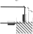
- FIG. 1 An embodiment of the method for additive manufacturing according to the present invention is described in Figure 1
- the liquid photoresist shown as a gray striped area is irradiated with a first light source at a first wavelength ⁇ 1 and with a second light source at a second wavelength ⁇ 2 .
- the 3D structured form according to the present invention is not particularly limited. Because the curing of the photoresist only takes place at the position that is irradiated by the first light source and by the second light source with a time interval of less than 1 ms, structures of less than 10 ⁇ m, preferably less than 1 ⁇ m, can be produced.
- the minimum achievable structure size is not particularly limited. In one embodiment, the structure has a size of at least one tenth of the wavelength of the light sources used.
- the 3D structured form can, for example, be a prosthesis, a cell template with controlled microstructuring or a metamaterial or be used in microoptics and microfluidics.
- the step i) of providing the liquid photoresist comprising at least one monomer and at least one photoinitiator system according to the present invention is not particularly limited.
- the liquid photoresist is provided in a container in step i).
- the container is a glass container or a plastic container that is optically transparent for the wavelengths used.
- a non-transparent container can be used that has suitable openings for imaging lenses.
- the container encloses a volume that is larger than the 3D structured shape to be printed or a portion thereof.
- a substrate that supports the produced 3D structured shape is located in the container.
- the liquid photoresist can be provided directly on the substrate without a container.
- This embodiment can be used, for example, if the irradiation direction of the first light source is not the same as the irradiation direction of the second light source according to the invention.
- the substrate can be a transparent surface.
- the substrate is a stage or is mounted on a stage that can be moved in the axial direction at least along the z-axis.
- the z-axis is the axis that runs perpendicular to the layers that are built up in the additive manufacturing process in one embodiment.
- the stage is movable in the direction of the x-, y- and z-axis. Due to the additional mobility of the stage laterally in the x- and y-directions, large structures can also be produced, since the laterally limited image field of commercially available lenses can be overcome.
- the 3D structured form is built up layer by layer along the z-axis.
- the stage is in the z-direction moved.
- the first light source with the first wavelength ⁇ 1 and the second light source with the second wavelength ⁇ 2 are not particularly limited as long as ⁇ 1 ⁇ ⁇ 2.
- the wavelength of the first light source and the second light source is each in a range between 190 nm and 900 nm.
- a laser or a light-emitting diode can be used as the light source.
- a light source with a wavelength in the UV/VIS or infrared range is used as the first light source and second light source. More preferably, a laser is used as the first light source and as the second light source.
- the first wavelength ⁇ 1 and the second wavelength ⁇ 2 depend on the choice of the photoinitiator system.
- the first light source and the second light source are lasers, with at least one of the lasers being a pulsed laser.
- a "pulsed laser” is understood to mean a laser that emits radiation in temporally discrete pulses. If no pulsed laser is used as the laser, the laser is a continuous wave laser. A “continuous wave laser” is a continuously excited laser.
- both light sources are pulsed lasers.
- the pulse duration, pulse repetition rate, irradiation duration and irradiation power are not particularly restricted and can be selected to suit the lifetimes of the states of the photoinitiator system. By using a suitably pulsed laser, spatially selective curing can therefore be achieved particularly easily.
- the arrangement of the first light source and the second light source relative to one another is not particularly limited according to the present invention, as long as the first light source and the second light source can irradiate the photoresist so that the photoresist hardens at the position of irradiation by the first light source and the second light source with a time interval of less than 1 ms.
- the irradiation direction of the first light source and the second light source is different according to the invention.
- the irradiation direction of the first light source is the same as the irradiation direction of the second light source.
- a device with such an alignment of the first light source and the second light source can be realized without great expenditure on equipment.
- the irradiation direction of the first light source is different from the irradiation direction of the second light source.
- This different spatial arrangement of the first light source and the second light source makes it particularly easy to achieve the spatial selectivity of the curing of the photoresist.
- the irradiation direction of the first light source has an angle in a range from 45° to 135°, preferably from 60° to 120°, particularly preferably from 80° to 100°, to the irradiation direction of the second light source with respect to the focal plane of the two light sources.
- Such an angle can achieve a particularly advantageous spatial selectivity of the curing of the photoresist.
- step ii) the 3D structured form to be produced is imaged in at least one of the focal planes of the first light source and the second light source.
- micromirror actuators can be used. These micromirror actuators have short switching times of only a few microseconds. This means that a single plane in the photoresist can be exposed within microseconds.
- liquid crystal displays can be imaged. These have switching times of a few milliseconds.
- the liquid photoresist according to the present invention is not particularly limited as long as it comprises at least one monomer and at least one photoinitiator system and is in a liquid state.
- the photoresist comprises from 70% by weight to 99.99% by weight, preferably from 85% by weight to 99.5% by weight, particularly preferably from 95% by weight to 99% by weight, of the at least one monomer and from 0.01% by weight to 30% by weight, preferably from 0.5% by weight to 15% by weight, particularly preferably from 1% by weight to 5% by weight, of the at least one photoinitiator system.
- the monomer and/or the photoinitiator system can also be dissolved in a solvent, in which case the combination of monomer and solvent and photoinitiator system and solvent then correspond to the parts by weight mentioned above.
- the choice of solvent is not particularly restricted.
- a solvent with low volatility and low toxicity is preferred, for example dimethyl sulfoxide, anisole or 2-propanol.
- the at least one monomer used in the present invention is not particularly limited as long as it is curable by photopolymerization.
- the monomer may be monofunctional or multifunctional.
- Multifunctional may mean bifunctional, trifunctional, or higher functionality than trifunctional.
- a monomer having only one type of functionality or a mixture of monomers having different functionalities may be used.
- at least one multifunctional monomer is used.
- the one monomer may be at least one member of the group consisting of vinylpyrrolidone, acrylonitrile, (meth)acrylic acid, vinyl acetate, methyl(meth)acrylate, ethyl acrylate, (iso)butyl vinyl ether, vinyl butyrate, methylacrylamide, isopropylacrylamide, tricyclo[5.2.1.0 2,6 ]decanedimethanol di(meth)acrylate, polyethylene glycol di(meth)acrylate, bisphenol A ethoxyal di(meth)acrylate, bis(acrylamide), pentaerythritol tri(meth)acrylate, trimethylolpropane tri(meth)acrylate, trimethylolpropane propoxylate tri(meth)acrylate, trimethylolpropane ethoxylate tri(meth)acrylate, glycerol propoxylate tri(meth)acrylate, di(trimethylolpropane)tetra(meth)acrylate, pen
- the at least one photoinitiator system is not particularly limited.
- the term "Photoinitiator system” is understood to mean a system that only forms a radical that can start the polymerization of the at least one monomer of the liquid photoresist when irradiated with the first light source at a first wavelength ⁇ 1 and with the second light source at a second wavelength ⁇ 2 with a time interval of less than 1 ms.
- the photoinitiator system comprises at least one photoinitiator. This can be present directly as a compound in the photoinitiator system or can be synthesized in situ using reactants.
- a "photoinitiator” is understood to mean a compound that, after absorbing radiation, forms a radical that enables the photoresist to harden.
- the photoinitiator system After the absorption of a first photon with the first wavelength ⁇ 1 of the first light source, the photoinitiator system goes into a "dormant intermediate state". This intermediate state has no curing properties. As a result of the absorption of a second photon with the second wavelength ⁇ 2 ⁇ ⁇ 1 of the second light source, a radical is formed in the photoinitiator system that can cure the at least one monomer.
- the first photon with the wavelength ⁇ 1 and the second photon with the wavelength ⁇ 2 can be absorbed by just one component of the photoinitiator system or by different components of the photoinitiator system.
- the components of the photoinitiator system are not particularly restricted as long as at least one photoinitiator is included.
- the photoinitiator system can comprise at least one component of a photosensitizer and a photoacid generator.
- a photosensitizer is understood to mean a compound which acts as an energy carrier or radical generator for a photoinitiator in a light-induced reaction.
- the dormant intermediate state returns to the ground state if no second photon of the second wavelength ⁇ 2 is absorbed by the photoinitiator system.
- the duration of the return to the ground state is less than 1 s and, more preferably, less than 1 ms. Due to this short duration of the return to the ground state The selective spatial curing of the photoresist can be achieved particularly advantageously and fast printing processes can be enabled.
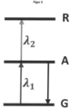
- FIG. 2 A schematic representation of the energy levels of the photoinitiator system is shown in Figure 2
- the dormant intermediate state is marked with “A” and the hardening state is marked with "R”.
- the dormant intermediate state has at most a low absorption of a photon of the first wavelength ⁇ 1.
- the dormant intermediate state has no absorption of a photon of the first wavelength ⁇ 1. This can improve the spatial selectivity of the curing of the photoresist.
- the provision of the photoinitiator system that cures the photoresist according to the present invention is not particularly limited.
- at least one component can be used that absorbs both the first photon of wavelength ⁇ 1 and the second photon of wavelength ⁇ 2 .
- at least two components can be used, with at least one component absorbing the first photon of wavelength ⁇ 1 and at least one further component absorbing the second photon of wavelength ⁇ 2 .
- Typical photoinitiators work when a photoinitiator molecule absorbs a photon to move from the ground state (S 0 ) to the excited singlet state (S i ). Through “intercombination” (intersystem crossing), the molecule can move to the triplet state (T i ). Starting from one of these two states (S i or T i ), photoinitiators form radicals by bond cleavage (Norrish reaction type I) or by hydrogen elimination (Norrish reaction type II).
- Bond cleavage according to Norrish reaction type I or II can only take place if the energy required for this is significantly lower than the state energy of the compound. If this is not the case, bond cleavage and the associated radical formation are extremely unlikely. Examples of components of a photoinitiator system according to the invention that undergo bond cleavage according to Norrish reaction type I or II are given below.
- the photoinitiator system comprises at least one member of a group consisting of an ⁇ -diketone, a naphthyl ester, carbazole, an oligothiophene, a p-phenylbenzoyl derivative, a phenylphenacyl derivative and phenothiazine.
- ⁇ -diketones examples include benzil, diacetyl and camphorquinone.
- T n triplet state
- This excitation can occur stepwise if benzil is first optically excited to the triplet ground state (T 1 ).
- T 1 triplet ground state
- This excitation can be achieved with a wavelength ⁇ 440 nm.
- the T 1 state has an absorption band with a maximum at a wavelength of 480 nm. Radicals can be formed from this state.
- diacetyl In its ground state, diacetyl absorbs light with a wavelength of ⁇ 500 nm. In contrast to benzil, diacetyl has the T 1 -T n absorption band with Absorption maximum in the near infrared range (> 600 nm). It is advantageous that the absorption spectra of the S 0 -S i and T 1 -T n transitions hardly overlap. However, in the case of diacetyl, hydrogen elimination already takes place in the T 1 state, which depletes the T 1 state. This can be counteracted with a sufficiently high intensity of the near infrared radiation source, which induces the T 1 -T n transition.
- Camphorquinone behaves similarly to diacetyl.
- the energy level of the triplet ground state T 1 is around 250 kJ/mol.
- Examples of such naphthyl esters are phenyl-1-naphthoate, phenyl-2-naphthoate, methyl-1-naphthoate, methyl-2-naphthoate, naphthalen-1-yl benzoate, naphthalen-2-yl benzoate, naphthalen-1-yl acetate and naphthalen-2-yl acetate.
- the energy required for bond cleavage is around 200 kJ/mol, depending on the exact molecular configuration. Nevertheless, bond cleavage from the T 1 state is not observed. The fact that no bond cleavage occurs from the T 1 state is due to large energy barriers between the T 1 state and the state of the dissociated bond. Bond cleavage and concomitant radical formation can be observed from higher excited triplet states.
- the naphthyl ester molecules can, for example, be converted indirectly into the T 1 state by using benzophenone as a photosensitizer and exciting it at 365 nm. After optical excitation, benzophenone is very likely to convert into the T 1 state via intercombination and can convert other molecules into a triplet state by means of energy transfer.
- the T 1 naphthyl esters can be optically excited at about 430 nm and converted into higher excited triplet states.
- Carbazole forms a carbazyl radical after a stepwise absorption of two photons of different wavelengths.
- the radical is formed from an excited singlet state. This is in contrast to the previously called molecules that generate radicals from the triplet state.
- Carbazole can be converted into the first excited singlet state with a wavelength ⁇ 365 nm. From there, further excitation into higher excited singlet states can be carried out optically with a wavelength > 500 nm.
- An example of an oligothiophene that has the above-mentioned properties is ⁇ -quinquethiophene.
- This can be excited step by step into higher triplet states (T n ) by irradiation with the first light source and with the second light source, from which it decays into radicals.
- T n triplet states
- a first laser with a wavelength of 420 nm and a second laser with a wavelength of 660 nm can be used.
- ⁇ -quinquethiophene is optically converted into a T n state.
- DZDS 3,3'-diazidodiphenylsulfone
- P-phenylbenzoyl derivatives can be excited to the T 1 state using a photosensitizer such as benzophenone.
- a photosensitizer such as benzophenone.
- Examples of such p-phenylbenzoyl derivatives are 4-biphenylcarboxylic acid, methyl 4-biphenylcarboxylate, phenyl[1,1'-biphenyl]-4-carboxylate and 5-phenyl[1,1'-biphenyl]-4-carbothioate.
- Further excitation at a wavelength of 420 nm results in bond cleavage, forming radicals.
- Benzophenone can be excited at a wavelength of 355 nm.
- p-phenylbenzoyl derivatives A similar behavior to that of the p-phenylbenzoyl derivatives can be observed for phenylphenacyl derivatives.
- p-phenylbenzoyl derivatives are 4-phenylacetophenone, 2-bromo-4'-phenylacetophenone, 2-chloro-4'-phenylacetophenone, 1-(4-biphenyl)-2-hydroxyethanone, 1-[1,1'-biphenyl]-4-yl-2-methoxyethanone, 1-biphenyl-4-yl-2-phenoxyethanone, 1-[1,1'-biphenyl]-4-yl-2-sulfanylethanone and 1-[1,1'-biphenyl]-4-yl-2-phenylsulfanylethanone.
- the phenylphenacyl derivative can be excited to the T 1 state.
- a photosensitizer such as benzophenone
- the phenylphenacyl derivative can be excited to the T 1 state.
- Another Excitation at a wavelength of 440 nm causes bond breaking, which leads to the formation of radicals.
- Benzophenone can be excited at 355 nm.
- Phenothiazine can be excited to the T 1 state by absorbing a photon with a first wavelength of 308 nm. Further excitation at a wavelength of 480 nm causes bond breaking, forming radicals.
- a stepwise radical formation by absorption of a first photon of the first wavelength ⁇ 1 and a second photon of the second wavelength ⁇ 2 can also be achieved using photocaged protecting groups.
- a photoinitiator with a protecting group is provided in the photoresist. The photoinitiator can only be excited after the protecting group has been separated by irradiation.
- An example of a compound with a photolabile protective group is benzodioxin. This decomposes when irradiated with a first wavelength of 320 nm.
- One of the reaction products is benzophenone. This can in turn be excited to the triplet ground state by irradiation at a second wavelength of 350 nm, which can trigger the formation of radicals.
- radicals can be generated in a two-stage process by in-situ photosynthesis of a photoinitiator.
- the photoresist comprises components that represent one or more reactants for the synthesis of a photoinitiator. Photoinduced by irradiation with a first wavelength ⁇ 1 , a reaction is started that converts these reactants into a photoinitiator. The synthesized photoinitiator is then excited by irradiation with a second wavelength ⁇ 2 so that it forms a radical.
- At least one monomer of the photoresist should be inert towards the reactants and the intermediates of the synthesis of the photoinitiator.
- Starting materials for such in-situ photosynthesis of a photoinitiator can be, for example, 2,5-diphenyl-3,4-benzofuran or thioxanthone-anthracene.
- 2,5-diphenyl-3,4-benzofuran can be converted into 1,2-dibenzoylbenzene in a first step.
- methylene blue can be used as a photosensitizer.
- Methylene blue can be excited with radiation at a first wavelength ⁇ 1 of 632 nm, whereby it can bring 2,5-diphenyl-3,4-benzofuran into the triplet state, which then converts into 1,2-dibenzoylbenzene.
- the latter can be excited by irradiation at a second wavelength ⁇ 2 of 365 nm.
- thioxanthone-anthracene reacts to form a thioxanthone-anthracene endoperoxide. This decomposes into two radicals when irradiated at a second wavelength ⁇ 2 of 400 nm.
- photochromism is the property of a substance to change its absorption behavior when exposed to light. The effect occurs when a compound undergoes a reversible conversion between two isomers.
- the photochromic property can be utilized in the present invention by reversibly switching a compound between a transparent and an absorbing state.
- photochromic compounds examples include 2-methoxynaphthalene and spiropyrans.
- 2-Methoxynaphthalene is a photochromic compound that exhibits an absorption band at a wavelength of 300 nm in the cis state. After absorbing a photon of the first wavelength ⁇ 1 , the compound can switch to the trans state, thereby forming dimers. Alternatively, the compound can transition to a triplet state and serve as a photosensitizer for excitation of triplet states at a second wavelength ⁇ 2 of 326 nm.
- a spiropyran that meets the above-mentioned properties is 1,3,3-trimethylindolino-6'-nitrobenzopyrylospiran. This is isomerized to merocyanine upon irradiation with a first wavelength ⁇ 1 in the blue or UV range. Upon absorption of a photon of a second wavelength ⁇ 2 in the visible range, for example 532 nm, merocyanine is converted into a reactive species that can cause the photoresist to harden. The light-induced isomerization of spiropyran is reversible.
- quenching refers to a process in which a fluorophore loses its fluorescence intensity. This happens, for example, when a fluorophore that is in an excited state releases its excitation energy to another molecule by means of an energy transfer. This energy transfer can occur, for example, through collisions or dipole-dipole interactions. Dipole-dipole fluorescence quenching takes place when the spectral emission band of the fluorophore and the absorption band of the quencher overlap. For high energy transfer efficiency, the distance between the energy levels of the quencher and the fluorophore must not be large. The spectral distance is preferably less than 10 nm.
- the above mechanism can be used, by de-exciting a photoinitiator that has been excited with a photon of a first wavelength ⁇ 1 but has not yet decayed into a radical by a quencher compound, thereby suppressing the formation of radicals. If the quencher compound is locally "switched off" by irradiation of a second wavelength ⁇ 2 , radicals can be formed by the photoinitiator.
- This embodiment of the present invention exploits the fact that photoinitiators often have a pH-dependent spectral shift in their absorption band.
- the pH value can be varied locally, for example, using a photoacid generator. This can form an acid when irradiated with a first wavelength ⁇ 1 . This acid shifts the absorption band of a photoinitiator so that it can absorb radiation of a second wavelength ⁇ 2 . In areas in which no acid was formed by irradiation with the first wavelength ⁇ 1 , the photoinitiator absorbs neither light of wavelength ⁇ 1 nor ⁇ 2 .
- the photoinitiator system comprises an ⁇ -diketone or a photochromic compound.
- a one-photon absorption by the at least one photoinitiator system can take place.
- a "one-photon absorption” refers to an absorption of a photon by a molecule.
- the term “two-photon absorption” means the simultaneous absorption of two photons by a molecule, whereby the photons are absorbed within a few femtoseconds.
- two photons can be used to excite from state "G” to state “A” to state “R” (cf. Figure 2 ), on the other hand, are absorbed in a time interval of a few picoseconds to a few milliseconds.
- one-photon absorption requires significantly less power per laser focus.
- the lower power requirement of the light source means that the technical effort required to carry out the process can be reduced.
- a washing step is carried out in which uncured parts of the photoresist are removed.
- FIG. 1 An example of the device according to the invention for additive manufacturing is shown in Figure 1 shown.
- a “device for additive manufacturing” is a Device in which the 3D structured form is gradually built up by curing the liquid photoresist. This device for additive manufacturing is to be distinguished from a device for subtractive manufacturing, in which material is removed from a form.
- the 3D structured shape produced in the device for additive manufacturing, the first light source with the first wavelength ⁇ 1 , the second light source with the second wavelength ⁇ 2 , the substrate for providing the liquid photoresist and the liquid photoresist correspond to the produced 3D structured shape, the first light source with the first wavelength ⁇ 1 , the second light source with the second wavelength ⁇ 2 , the substrate and the liquid photoresist of the method for additive manufacturing according to the invention.
- the substrate is located in a container, and the substrate is designed to support a 3D structured shape produced in the device for additive manufacturing.
- the container corresponds to the container of the method according to the invention.
- the substrate can be a stage or be mounted on a stage that corresponds to the stage of the method according to the invention for additive manufacturing.
- the present invention allows efficient parallelization of the three-dimensional curing of a liquid photoresist at a high resolution.
- costs can be reduced due to the reduction in the technical effort for implementing the invention compared to conventional two-photon lithography, since in the present invention the excitation can be carried out by means of step-by-step one-photon absorption.
- the parallelization provided by the present invention allows 3D structuring to be realized using projection-based methods.
- micromirror actuators can be used that have a short switching time of only a few microseconds. Therefore, a single layer of the liquid photoresist can be irradiated and
- conventional two-photon lithography often uses galvanometrically driven mirrors, which typically require a few milliseconds to completely irradiate a plane.
- the resolution axial to the projection of the 3D structured shape to be produced is improved in the present invention.
- minimum axial structure sizes of up to 10 ⁇ m are possible.
- the present invention enables even finer structuring, which is even below the size of the wavelength of the light sources used.
- photoresist monomer photoinitiator system 1 PETA diacetyl 99% by weight 1 wt.% 2 PETA 1,3,3-Trimethylindolino-6'-nitrobenzopyrylospirane 99% by weight 1 wt.% 3 PETA benzil 99% by weight 1 wt.% Pentaerythritol triacrylate (PETA): CAS 3524-68-3 Diacetyl: CAS 431-03-8 1,3,3-Trimethylindolino-6'-nitrobenzopyrylospirane: CAS 1498-88-0 Benzil: CAS 134-81-6
- the intensity in the focus of the laser with the wavelength of 440 nm was set to a maximum of 130 W/cm 2 .
- the intensity of the laser with the wavelength of 640 nm was a maximum of 690 W/cm 2 .
- the intensity of the laser with the wavelength of 405 nm was set to a maximum of 260 W/cm 2 .
- the intensity of the laser with the wavelength of 532 nm was a maximum of 96 kW/cm 2 .
- the intensity of the laser with the wavelength of 405 nm was set to a maximum of 16 W/cm 2 .
- the intensity of the laser with the wavelength of 532 nm was a maximum of 48 kW/cm 2 .
- an acousto-optical modulator (5 in Figure 3 ) was used.
- the powers were measured in the plane of the microscope objective pupil and converted into intensities based on a measurement of the width of the focused beam.
- Both laser beams were magnified, superimposed using a beam splitter and guided into a microscope objective (100x, NA 1.4, oil immersion).
- the lasers were focused through a microscope cover glass (170 ⁇ m thick) into a drop of the respective photoresist.
- the cover glass was moved by a piezo stage (1 in Figure 3 ) spatially.
- a digital camera (2 in Figure 3 ) the curing process in the focal plane could be monitored in real time.
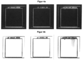
- Microscope images of the three measurement series for photoresist 1 are shown in Figures 4a and 4b shown.
- the intensity was varied along the vertical in the images.
- the lower end of the image corresponds to an intensity of 0 W/cm 2 and the upper end to the respective maximum value.
Landscapes
- Engineering & Computer Science (AREA)
- Chemical & Material Sciences (AREA)
- Materials Engineering (AREA)
- Physics & Mathematics (AREA)
- Manufacturing & Machinery (AREA)
- Optics & Photonics (AREA)
- Mechanical Engineering (AREA)
- Health & Medical Sciences (AREA)
- Toxicology (AREA)
- General Physics & Mathematics (AREA)
- Plasma & Fusion (AREA)
- Microelectronics & Electronic Packaging (AREA)
- Architecture (AREA)
- Structural Engineering (AREA)
- Spectroscopy & Molecular Physics (AREA)
- Exposure And Positioning Against Photoresist Photosensitive Materials (AREA)
- Polymerisation Methods In General (AREA)
Description
- Die vorliegende Erfindung betrifft ein Verfahren zur additiven Herstellung einer 3D-strukturierten Form und eine Vorrichtung zur additiven Herstellung einer 3D-strukturierten Form.
- Eine gängige Variante für die Herstellung 3D-gedruckter Formen ist die lichtinduzierte Polymerisation (Photopolymerisation). Ein flüssiger Photolack wird dabei durch die Bestrahlung mit Licht ausgehärtet. Unbelichtete Bereiche bleiben flüssig und werden während eines Entwicklungsschrittes ausgewaschen.
-
US 4 041 476 A offenbart ein Verfahren, eine Vorrichtung und ein Produkt, bei dem eine dreidimensionale Figur in situ in einem Medium mit zwei aktiven Komponenten geformt wird, indem zwei Strahlen in dem Medium zur Kreuzung gebracht werden. Die unterschiedlichen Komponenten werden so ausgewählt, dass sie auf das gleichzeitige Vorhandensein des Strahls ansprechen und entweder reagieren oder Reaktanten erzeugen, die den Schnittpunkt der Strahlen physikalisch spürbar oder unterscheidbar machen. - Die Grundvoraussetzung, um 3D-strukturierte Formen herzustellen, ist dabei, dass der Photolack räumlich selektiv ausgehärtet werden kann. Dafür haben sich mehrere Lösungen etabliert. Für Strukturgrößen im Mikrometerbereich wird beispielsweise die Zwei-Photonen-Lithographie eingesetzt. Bei dieser Lithographiemethode wird ein langwelliger Laser hoher Leistung in den flüssigen Photolack fokussiert. Da der Photolack größtenteils transparent für den Laser ist, kommt es nur direkt im Fokus zu einer Polymerisation. Dort werden Intensitäten erreicht, die groß genug sind, um mittels Zwei-Photonen-Absorption den Photolack auszuhärten. Diese hohen Intensitäten werden typischerweise mit Ultrakurzpuls-Lasern erreicht. Um ganze Volumina zu belichten, wird der fokussierte Laser im flüssigen Photolack gerastert.
- Ein Nachteil dieser Methode ist die fehlende Parallelisierung. Einzelne Bildpunkte werden seriell belichtet. Dies hat hauptsächlich zwei Gründe: Werden mehrere Laserfokusse eng beieinander erzeugt, wie es für eine Parallelisierung notwendig ist, kommt es auch jenseits der Fokusebene zu einer Überlagerung benachbarter Laserstrahlen. Auch dort werden Intensitäten erreicht, die ausreichend sind, um den Photolack auszuhärten. Dadurch geht die notwendige räumliche Selektivität für die Herstellung einer strukturierten Form in einem 3D-Druckprozess verloren. Des Weiteren werden die Leistungsanforderungen an den Laser so groß, dass diese nur noch mit einem hohen technischen Aufwand erreicht werden können.
- Der vorliegenden Erfindung liegt daher die Aufgabe zugrunde, ein Verfahren und eine Vorrichtung bereitzustellen, die einen parallelisierten 3D-Druck für Strukturgrößen im Mikrometerbereich, ausgehend von einem flüssigen Photolack, ermöglichen.
- Anspruch 1 definiert das Verfahren gemäß der Erfindung und Anspruch 6 definiert die Vorrichtung gemäß der Erfindung.
- Ein erster Aspekt der Erfindung betrifft ein Verfahren zur additiven Herstellung einer 3D-strukturierten Form, umfassend die Schritte in der folgenden Reihenfolge:
- i) Bereitstellen eines flüssigen Photolacks, umfassend mindestens ein Monomer und mindestens ein Photoinitiatorsystem,
- ii) Bestrahlen des flüssigen Photolacks mit einer ersten Lichtquelle bei einer ersten Wellenlänge λ1 und mit einer zweiten Lichtquelle bei einer zweiten Wellenlänge λ2, wobei λ1 ≠ λ2 und
eine Aushärtung des flüssigen Photolacks zu der 3D-strukturierten Form nur an der Position erfolgt, die von der ersten Lichtquelle und der zweiten Lichtquelle mit einem zeitlichen Abstand von kleiner als 1 ms bestrahlt wird. - Die vorliegende Erfindung ermöglicht eine vorteilhafte parallelisierte Herstellung einer 3D-strukturierten Form, da die Aushärtung des Photolacks nur an der Position erfolgt, die von der ersten Lichtquelle und der zweiten Lichtquelle mit einem zeitlichen Abstand von kleiner als 1 ms bestrahlt wird. Bevorzugt entspricht diese Position der Fokusebene von mindestens einer aus der ersten Lichtquelle und der zweiten Lichtquelle.
- Gemäß der vorliegenden Erfindung erfolgt die Aushärtung des flüssigen Photolacks zu der 3D-strukturierten Form nur an der Position, die von der ersten Lichtquelle und der zweiten Lichtquelle mit einem zeitlichen Abstand von kleiner als 1 ms bestrahlt wird. In einer Ausführungsform bestrahlen die erste Lichtquelle und die zweite Lichtquelle den flüssigen Photolack sequenziell mit einem zeitlichen Abstand von kleiner als 1 ms, bevorzugt kleiner als 1 µs. In einer weiteren Ausführungsform bestrahlen die erste Lichtquelle und die zweite Lichtquelle den flüssigen Photolack gleichzeitig.
- Erfindungsgemäß ist unter einem "Verfahren zur additiven Herstellung" (d.h. "additives Verfahren") ein Verfahren zu verstehen, bei dem die 3D-strukturierte Form durch Aushärtung des flüssigen Photolacks schrittweise aufgebaut wird. Das erfindungsgemäße Verfahren zur additiven Herstellung ist zu unterscheiden von einem Verfahren zur subtraktiven Herstellung (d.h. "subtraktives Verfahren"), bei dem Material einer Form abgetragen wird.
- Eine Ausführungsform des Verfahrens zur additiven Herstellung gemäß der vorliegenden Erfindung ist in
Figur 1 gezeigt. Der als grau gestreifte Fläche dargestellte flüssige Photolack wird mit einer ersten Lichtquelle bei einer ersten Wellenlänge λ1 und mit einer zweiten Lichtquelle bei einer zweiten Wellenlänge λ2 bestrahlt. - Die 3D-strukturierte Form gemäß der vorliegenden Erfindung ist nicht besonders eingeschränkt. Dadurch dass die Aushärtung des Photolacks nur an der Position erfolgt, die von der ersten Lichtquelle und von der zweiten Lichtquelle mit einem zeitlichen Abstand von kleiner als 1 ms bestrahlt wird, können Strukturierungen von kleiner als 10 µm, bevorzugt kleiner als 1 µm, erzeugt werden. Die minimal erreichbare Strukturgröße ist nicht besonders eingeschränkt. In einer Ausführungsform weist die Strukturierung eine Größe von mindestens einem Zehntel der Wellenlänge der verwendeten Lichtquellen auf.
- Die 3D-strukturierte Form kann beispielsweise eine Prothese, ein Zelltemplat mit kontrollierter Mikrostrukturierung oder ein Metamaterial sein oder in der Mikrooptik und Mikrofluidik eingesetzt werden.
- Der Schritt i) des Bereitstellens des flüssigen Photolacks, umfassend mindestens ein Monomer und mindestens ein Photoinitiatorsystem, gemäß der vorliegenden Erfindung ist nicht besonders eingeschränkt.
- In einer Ausführungsform wird der flüssige Photolack in dem Schritt i) in einem Behälter bereitgestellt. Gemäß einer Ausführungsform ist der Behälter ein Glasgefäß oder ein Kunststoffgefäß, das optisch transparent für die verwendeten Wellenlängen ist. Alternativ kann ein nichttransparenter Behälter verwendet werden, der über passende Öffnungen für Abbildungslinsen verfügt. Gemäß einer Ausführungsform schließt der Behälter ein Volumen ein, das größer als die zu druckende 3D-strukturierte Form oder ein Teilstück dieser ist. Gemäß einer Ausführungsform der vorliegenden Erfindung befindet sich in dem Behälter ein Substrat, das die hergestellte 3D-strukturierte Form stützt.
- In einer weiteren Ausführungsform kann der flüssige Photolack ohne Behälter direkt auf dem Substrat bereitgestellt werden. Diese Ausführungsform kann beispielsweise eingesetzt werden, wenn nicht erfindungsgemäß die Bestrahlungsrichtung der ersten Lichtquelle gleich der Bestrahlungsrichtung der zweiten Lichtquelle ist. Dabei kann das Substrat in dieser Ausführungsform eine transparente Fläche sein.
- Bevorzugt ist das Substrat eine Bühne oder auf einer Bühne angebracht, die mindestens entlang der z-Achse in axiale Richtung bewegt werden kann. Die z-Achse ist die Achse, die senkrecht zu den Schichten verläuft, die in dem Verfahren zur additiven Herstellung in einer Ausführungsform aufgebaut werden. Gemäß einer weiteren Ausführungsform ist die Bühne in Richtung der x-, y- und z-Achse beweglich. Durch die zusätzliche Beweglichkeit der Bühne in x- und y-Richtung lateral können auch große Strukturen hergestellt werden, da das lateral limitierte Bildfeld handelsüblicher Linsen überwunden werden kann.
- Gemäß einer bevorzugten Ausführungsform wird die 3D-strukturierte Form schichtweise entlang der z-Achse aufgebaut. Dabei wird bevorzugt die Bühne in z-Richtung bewegt.
- In der vorliegenden Erfindung sind die erste Lichtquelle mit der ersten Wellenlänge λ1 und die zweite Lichtquelle mit der zweiten Wellenlänge λ2 nicht besonders eingeschränkt, solange λ1 ≠ λ2 ist. Bevorzugt ist die Wellenlänge der ersten Lichtquelle und der zweiten Lichtquelle jeweils in einem Bereich zwischen 190 nm und 900 nm. Beispielsweise kann als Lichtquelle ein Laser oder eine Leuchtdiode verwendet werden. Bevorzugt wird als erste Lichtquelle und zweite Lichtquelle eine Lichtquelle mit einer Wellenlänge im UV/VIS- oder Infrarot-Bereich verwendet. Weiter bevorzugt wird ein Laser als erste Lichtquelle und als zweite Lichtquelle verwendet. Die erste Wellenlänge λ1 und die zweite Wellenlänge λ2 sind abhängig von der Wahl des Photoinitiatorsystems.
- Gemäß einer weiteren Ausführungsform sind die erste Lichtquelle und die zweite Lichtquelle Laser, wobei mindestens einer der Laser ein gepulster Laser ist. In der vorliegenden Erfindung ist unter einem "gepulsten Laser" ein Laser zu verstehen, der Strahlung in zeitlich diskreten Pulsen emittiert. Falls kein gepulster Laser als Laser verwendet wird, ist der Laser ein Dauerstrichlaser. Ein "Dauerstrichlaser" ist ein kontinuierlich angeregter Laser. In einer Ausführungsform sind beide Lichtquellen gepulste Laser. Die Pulsdauer, Pulswiederholrate, Bestrahlungsdauer und Bestrahlungsleistung sind dabei nicht besonders eingeschränkt und können passend zu den Lebensdauern der Zustände des Photoinitiatorsystems gewählt werden. Durch die Verwendung eines passend gepulsten Lasers kann eine räumlich selektive Aushärtung deshalb besonders leicht erreicht werden.
- Die Anordnung der ersten Lichtquelle und der zweiten Lichtquelle zueinander ist gemäß der vorliegenden Erfindung nicht besonders eingeschränkt, solange die erste Lichtquelle und die zweite Lichtquelle den Photolack bestrahlen können, so dass an der Position der Bestrahlung durch die erste Lichtquelle und die zweite Lichtquelle mit einem zeitlichen Abstand von kleiner als 1 ms der Photolack aushärtet. Die Bestrahlungsrichtung der ersten Lichtquelle und der zweiten Lichtquelle ist erfindungsgemäß unterschiedlich.
- In einer nicht erfindungsgemäßen Ausführungsform ist die Bestrahlungsrichtung der ersten Lichtquelle gleich der Bestrahlungsrichtung der zweiten Lichtquelle. Eine Vorrichtung mit einer solchen Ausrichtung der ersten Lichtquelle und der zweiten Lichtquelle kann ohne großen apparativen Aufwand realisiert werden.
- Erfindungsgemäß ist die Bestrahlungsrichtung der ersten Lichtquelle verschieden von der Bestrahlungsrichtung der zweiten Lichtquelle. Durch diese unterschiedliche räumliche Anordnung der ersten Lichtquelle und der zweiten Lichtquelle kann besonders leicht die räumliche Selektivität der Aushärtung des Photolacks erreicht werden.
- Gemäß einer Ausführungsform der vorliegenden Erfindung weist die Bestrahlungsrichtung der ersten Lichtquelle zu der Bestrahlungsrichtung der zweiten Lichtquelle bezüglich der Fokusebene der beiden Lichtquellen einen Winkel in einem Bereich von 45° bis 135°, bevorzugt von 60° bis 120°, besonders bevorzugt von 80° bis 100°, auf. Durch einen solchen Winkel kann eine besonders vorteilhafte räumliche Selektivität der Aushärtung des Photolacks erreicht werden.
- Einer Ausführungsform des erfindungsgemäßen Verfahrens entsprechend wird im Schritt ii) die herzustellende 3D-strukturierte Form in mindestens eine der Fokusebenen der ersten Lichtquelle und der zweiten Lichtquelle abgebildet. Dabei können beispielsweise Mikrospiegelaktoren verwendet werden. Diese Mikrospiegelaktoren haben kurze Schaltzeiten von nur einigen Mikrosekunden. Dadurch kann eine einzelne Ebene im Photolack innerhalb von Mikrosekunden belichtet werden. Alternativ können Flüssigkristallanzeigen abgebildet werden. Diese besitzen Schaltzeiten von einigen Millisekunden.
- Der flüssige Photolack gemäß der vorliegenden Erfindung ist nicht besonders eingeschränkt, solange er mindestens ein Monomer und mindestens ein Photoinitiatorsystem umfasst und in einem flüssigen Zustand vorliegt.
- In einer Ausführungsform umfasst der Photolack von 70 Gew.-% bis 99,99 Gew.-%, bevorzugt von 85 Gew.-% bis 99,5 Gew.-%, besonders bevorzugt von 95 Gew.-% bis 99 Gew.-%, des mindestens einen Monomers und von 0,01 Gew.-% bis 30 Gew.-%, bevorzugt von 0,5 Gew.-% bis 15 Gew.-%, besonders bevorzugt von 1 Gew.-% bis 5 Gew.-%, des mindestens einen Photoinitiatorsystems. Das Monomer und/oder das Photoinitiatorsystem können auch in einem Lösemittel gelöst vorliegen, wobei dann jeweils die Kombination aus Monomer und Lösemittel und Photoinitiatorsystem und Lösemittel den obengenannten Gewichtsteilen entsprechen. Die Wahl des Lösemittels ist nicht besonders eingeschränkt. Bevorzugt ist ein wenig flüchtiges und wenig giftiges Lösemittel, zum Beispiel Dimethylsulfoxid, Anisol oder 2-Propanol.
- Das in der vorliegenden Erfindung verwendete mindestens eine Monomer ist nicht besonders eingeschränkt, solange es durch Photopolymerisation aushärtbar ist. Das Monomer kann monofunktionell oder multifunktionell sein. Dabei kann "multifunktionell" bifunktionell, trifunktionell oder eine höhere Funktionalität als trifunktionell bedeuten. In der vorliegenden Erfindung kann ein Monomer mit nur einer Art von Funktionalität oder ein Gemisch von Monomeren verschiedener Funktionalitäten verwendet werden. Bevorzugt wird mindestens ein multifunktionelles Monomer verwendet.
- Das eine Monomer kann mindestens ein Bestandteil der Gruppe, bestehend aus Vinylpyrrolidon, Acrylnitril, (Meth)acrylsäure, Vinylacetat, Methyl(meth)acrylat, Ethylacrylat, (Iso)Butylvinylether, Vinylbutyrat, Methylacrylamid, Isopropylacrylamid, Tricyclo[5.2.1.02,6]decandimethanoldi(meth)acrylat, Polyethylenglykoldi(meth)acrylat, Bisphenol A-Ethoxyaldi(meth)acrylat, Bis(acrylamid), Pentaerythritoltri(meth)acrylat, Trimethylolpropantri(meth)acrylat, Trimethylolpropanpropoxylattri(meth)acrylat, Trimethylolpropanethoxylattri(meth)acrylat, Glycerolpropoxylattri(meth)acrylat, Di(trimethylolpropan)tetra(meth)acrylat, Pentaerythritoltetra(meth)acrylat und Dipentaerythritol(penta-/hexa)-(meth)acrylat, sein.
- Das mindestens eine Photoinitiatorsystem gemäß der vorliegenden Erfindung ist nicht besonders eingeschränkt. Erfindungsgemäß wird unter dem Begriff "Photoinitiatorsystem" ein System verstanden, das erst durch das Bestrahlen mit der ersten Lichtquelle bei einer ersten Wellenlänge λ1 und mit der zweiten Lichtquelle bei einer zweiten Wellenlänge λ2 mit einem zeitlichen Abstand von kleiner als 1 ms ein Radikal bildet, das die Polymerisation des mindestens einen Monomers des flüssigen Photolacks starten kann. Das Photoinitiatorsystem umfasst mindestens einen Photoinitiator. Dieser kann direkt als Verbindung in dem Photoinitiatorsystem vorliegen oder durch Edukte in situ synthetisiert werden. In der vorliegenden Erfindung ist unter einem "Photoinitiator" eine Verbindung zu verstehen, die nach Absorption von Strahlung ein Radikal bildet, das die Aushärtung des Photolacks ermöglicht.
- Das Photoinitiatorsystem geht nach der Absorption eines ersten Photons mit der ersten Wellenlänge λ1 der ersten Lichtquelle in einen "dormanten Zwischenzustand" über. Dieser Zwischenzustand besitzt keine aushärtende Eigenschaft. In Folge der Absorption eines zweites Photon mit der zweiten Wellenlänge λ2 ≠ λ1 der zweiten Lichtquelle wird in dem Photoinitiatorsystem ein Radikal gebildet, das das mindestens eine Monomer aushärten kann. Dabei kann das erste Photon der Wellenlänge λ1 und das zweite Photon der Wellenlänge λ2 von nur einem Bestandteil des Photoinitiatorsystems oder von unterschiedlichen Bestandteilen des Photoinitiatorsystems absorbiert werden.
- Die Bestandteile des Photoinitiatorsystems sind nicht besonders eingeschränkt, solange mindestens ein Photoinitiator umfasst ist. Weiterhin kann das Photoinitiatorsystem mindestens einen Bestandteil aus einem Photosensibilisator und einem Photosäuregenerator umfassen. Erfindungsgemäß wird unter einem "Photosensibilisator" eine Verbindung verstanden, die bei einer lichtinduzierten Reaktion als Energieträger oder Radikalbildner für einen Photoinitiator wirkt.
- Erfindungsgemäß kehrt der dormante Zwischenzustand wieder in den Grundzustand zurück, falls kein zweites Photon der zweiten Wellenlänge λ2 von dem Photoinitiatorsystem absorbiert wird. In einer Ausführungsform beträgt die Dauer der Rückkehr in den Grundzustand weniger als 1 s und, weiter bevorzugt, weniger als 1 ms. Aufgrund dieser kurzen Dauer der Rückkehr in den Grundzustand kann besonders vorteilhaft die selektive räumliche Aushärtung des Photolacks erreicht und schnelle Druckvorgänge ermöglicht werden.
- Eine schemenhafte Darstellung der Energieniveaus des Photoinitiatorsystems ist in
Figur 2 gezeigt. Der dormante Zwischenzustand ist mit "A" und der aushärtende Zustand ist mit "R" gekennzeichnet. - In einer Ausführungsform weist der dormante Zwischenzustand höchstens eine geringe Absorption eines Photons der ersten Wellenlänge λ1 auf. Bevorzugt weist der dormante Zwischenzustand keine Absorption eines Photons der ersten Wellenlänge λ1 auf. Dadurch kann die räumliche Selektivität der Aushärtung des Photolacks verbessert werden.
- Die Bereitstellung des Photoinitiatorsystems, das den Photolack aushärtet, gemäß der vorliegenden Erfindung ist nicht besonders eingeschränkt. Dabei kann in einer Ausführungsform mindestens ein Bestandteil verwendet werden, der sowohl das erste Photon der Wellenlänge λ1 und das zweite Photon der Wellenlänge λ2 absorbiert. In einer weiteren Ausführungsform können mindestens zwei Bestandteile verwendet werden, wobei mindestens ein Bestandteil das erste Photon der Wellenlänge λ1 und mindestens ein weiterer Bestandteil das zweite Photon der Wellenlänge λ2 absorbiert.
- Dabei können, abhängig von den Bestandteilen des Photoinitiatorsystems, verschiedene Mechanismen verwendet werden.
- Gemäß einer Ausführungsform umfasst das Photoinitiatorsystem mindestens eines aus 1) einer Verbindung mit einer hohen Bindungsbruchenergie, 2) einer Verbindung mit einer photolabilen Schutzgruppe, 3) einem in-situ photosynthetisierten Initiator, 4) einer photochromischen Verbindung, 5) einem Quencher und 6) einem pH-sensitiven Photoinitiator.
- 1) Verbindung mit hoher Bindungsbruchenergie
- Typische Photoinitiatoren funktionieren, indem ein Photoinitiatormolekül ein Photon absorbiert, um vom Grundzustand (S0) in den einen angeregten Singulett-Zustand (Si) überzugehen. Durch "Interkombination" (engl.: "intersystem crossing") kann das Molekül in den Triplett-Zustand (Ti) übergehen. Ausgehend von einem dieser beiden Zustände (Si oder Ti) kommt es bei Photoinitiatoren durch Bindungsspaltung (Norrish-Reaktion vom Typ I) oder durch Wasserstoffabspaltung (Norrish-Reaktion vom Typ II) zur Radikalbildung.
- Die Bindungsspaltung gemäß Norrish-Reaktion Typ I oder II kann nur stattfinden, wenn die dafür notwendige Energie deutlich geringer als die Zustandsenergie der Verbindung ist. Ist dies nicht der Fall, sind eine Bindungsspaltung und die damit einhergehende Radikalbildung äußerst unwahrscheinlich. Im Folgenden werden Beispiele für Bestandteile eines erfindungsgemäßen Photoinitiatorsystems genannt, die eine Bindungsspaltung gemäß Norrish-Reaktion Typ I oder II eingehen.
- In einer Ausführungsform umfasst das Photoinitiatorsystem nach dem obengenannten Mechanismus 1) mindestens einen Bestandteil einer Gruppe, bestehend aus einem α-Diketon, einem Naphthylester, Carbazol, einem Oligothiophen, einem p-Phenylbenzoylderivat, einem Phenylphenacylderivat und Phenothiazin.
- Beispiele für α-Diketone, die in der vorliegenden Erfindung verwendet werden können, sind Benzil, Diacetyl und Campherchinon.
- Benzil geht eine Norrish-Reaktion vom Typ I ein, nachdem das Molekül in einen höheren Triplett-Zustand (Tn) angeregt wurde. Diese Anregung kann stufenweise erfolgen, wenn Benzil zunächst optisch in den Triplett-Grundzustand (T1) angeregt wird. Diese Anregung kann mit einer Wellenlänge < 440 nm erreicht werden. Der T1-Zustand besitzt eine Absorptionsbande mit Maximum bei einer Wellenlänge von 480 nm. Aus diesem Zustand können Radikale gebildet werden.
- Diacetyl absorbiert im Grundzustand Licht der Wellenlänge < 500 nm. Im Gegensatz zu Benzil besitzt Diacetyl die T1-Tn-Absorptionsbande jedoch mit Absorptionsmaximum im Nahinfrarot-Bereich (> 600 nm). Vorteilhaft ist, dass sich die Absorptionsspektren der S0-Si- und T1-Tn-Übergänge kaum überlappen. Allerdings findet bei Diacetyl im T1-Zustand bereits eine Wasserstoffabspaltung statt, wodurch der T1-Zustand verarmt. Dem kann mit einer ausreichend hohen Intensität der Nahinfrarot-Strahlungsquelle begegnet werden, wodurch der T1-Tn-Übergang induziert wird.
- Campherchinon verhält sich ähnlich wie Diacetyl.
- Für einige Naphthylester liegt das Energieniveau des Triplett-Grundzustands T1 bei etwa 250 kJ/mol. Solche Naphthylester sind beispielsweise Phenyl-1-Naphthoat, Phenyl-2-Naphthoat, Methyl-1-Naphthoat, Methyl-2-Naphthoat, Naphthalen-1-ylbenzoat, Naphthalen-2-ylbenzoat, Naphthalen-1-ylacetat und Naphthalen-2-ylacetat. Die für eine Bindungsspaltung notwendige Energie beträgt, abhängig von der genauen Molekülkonfiguration, etwa 200 kJ/mol. Dennoch ist eine Bindungsspaltung aus dem T1-Zustand nicht zu beobachten. Die Tatsache, dass es zu keinem Bindungsbruch aus dem T1-Zustand kommt, ist durch große Energiebarrieren zwischen dem T1-Zustand und dem Zustand der dissoziierten Bindung begründet. Eine Bindungsspaltung und eine damit einhergehende Radikalbildung kann aus höher angeregten Triplett-Zuständen beobachtet werden.
- Die Naphthylester-Moleküle können beispielsweise indirekt in den T1-Zustand überführt werden, indem Benzophenon als Photosensibilisator bei 365 nm angeregt wird. Benzophenon geht nach einer optischen Anregung mit sehr hoher Wahrscheinlichkeit via Interkombination in den T1-Zustand über und kann andere Moleküle mittels eines Energietransfers in einen Triplett-Zustand überführen. Die T1-Naphthylester können optisch bei etwa 430 nm angeregt und in höher angeregte Triplett-Zustände überführt werden.
- Carbazol bildet nach einer schrittweisen Absorption zweier Photonen unterschiedlicher Wellenlänge ein Carbazyl-Radikal. Das Radikal wird bei Carbazol aus einem angeregten Singulett-Zustand gebildet. Dies steht im Gegensatz zu den zuvor genannten Molekülen, die Radikale aus dem Triplett-Zustand generieren. Carbazol kann mit einer Wellenlänge < 365 nm in den ersten angeregten Singulett-Zustand überführt werden. Von dort kann eine weitere Anregung in höher angeregte Singulett-Zustände optisch mit einer Wellenlänge > 500 nm erfolgen.
- Ein Beispiel für ein Oligothiophen, das die obengenannten Eigenschaften aufweist, ist α-Quinquethiophen. Dieses kann schrittweise durch Bestrahlung mit der ersten Lichtquelle und mit der zweiten Lichtquelle in höhere Triplett-Zustände (Tn) angeregt werden, wobei es von diesen Zuständen in Radikale zerfällt. Dabei kann beispielsweise ein erster Laser mit einer Wellenlänge von 420 nm und ein zweiter Laser mit einer Wellenlänge von 660 nm verwendet werden. Zuerst wird α-Quinquethiophen optisch in einen Tn-Zustand überführt. Über einen Energietransfer können dann Photosensibilisatoren, die als Radikalbildner wirken, angeregt werden. Als Radikalbildner können beispielsweise 3,3'-Diazidodiphenylsulfon (DZDS) und 2,2-Dimethoxy-2-phenylacetophenon verwendet werden.
- P-Phenylbenzoylderivate könnten mit einem Photosensibilisator, wie beispielsweise Benzophenon, in den T1-Zustand angeregt werden. Beispiele für solche p-Phenylbenzoylderivate sind 4-Biphenylcarbonsäure, Methyl-4-Biphenylcarboxylat, Phenyl[1,1'-Biphenyl]-4-Carboxylat und 5-Phenyl[1,1'-Biphenyl]-4-Carbothioat. Durch eine weitere Anregung bei einer Wellenlänge von 420 nm kommt es zum Bindungsbruch, wodurch Radikale gebildet werden. Benzophenon kann hier bei einer Wellenlänge von 355 nm angeregt werden.
- Ein ähnliches Verhalten wie bei den p-Phenylbenzoylderivaten kann bei Phenylphenacylderivaten beobachtet werden. Beispiele für solche p-Phenylbenzoylderivate sind 4-Phenylacetophenon, 2-Brom-4'-phenylacetophenon, 2-Chlor-4'-phenylacetophenon, 1-(4-Biphenyl)-2-Hydroxyethanon, 1-[1,1'-Biphenyl]-4-yl-2-Methoxyethanon, 1-Biphenyl-4-yl-2-Phenoxyethanon, 1-[1,1'-Biphenyl]-4-yl-2-Sulfanylethanon und 1-[1,1'-Biphenyl]-4-yl-2-Phenylsulfanylethanon. Mithilfe eines Photosensibilisators, wie beispielsweise Benzophenon, kann das Phenylphenacylderivat in den T1-Zustand angeregt werden. Durch eine weitere Anregung bei einer Wellenlänge von 440 nm kommt es zum Bindungsbruch, wodurch Radikale gebildet werden. Benzophenon kann hier bei 355 nm angeregt werden.
- Phenothiazin kann bei Absorption eines Photons einer ersten Wellenlänge von 308 nm in den T1-Zustand angeregt werden. Durch eine weitere Anregung bei einer Wellenlänge von 480 nm kommt es zum Bindungsbruch, wodurch Radikale gebildet werden.
- Eine schrittweise Radikalbildung durch Absorption eines ersten Photons der ersten Wellenlänge λ1 und eines zweiten Photons der zweiten Wellenlänge λ2 kann auch unter Verwendung von photolabilen Schutzgruppen (engl. "caged") erreicht werden. Dabei wird ein Photoinitiator mit einer Schutzgruppe im Photolack bereitgestellt. Der Photoinitiator kann erst angeregt werden, nachdem die Schutzgruppe durch Bestrahlung abgetrennt wurde.
- Ein Beispiel für eine Verbindung mit einer photolabilen Schutzgruppe ist Benzodioxin. Dieses zerfällt unter Bestrahlung mit einer ersten Wellenlänge von 320 nm. Als Reaktionsprodukt entsteht dabei unter anderem Benzophenon. Dieses kann wiederum durch Bestrahlung bei einer zweiten Wellenlänge von 350 nm in den Triplett-Grundzustand angeregt werden, wodurch eine Radikalbildung ausgelöst werden kann.
- Gemäß einer weiteren Ausführungsform können Radikale in einem zweistufigen Prozess durch in-situ Photosynthese eines Photoinitiators generiert werden. Dabei umfasst der Photolack Bestandteile, die ein oder mehrere Edukte zur Synthese eines Photoinitiators darstellen. Photoinduziert durch Bestrahlung mit einer ersten Wellenlänge λ1 wird eine Reaktion gestartet, die diese Edukte zu einem Photoinitiator umsetzt. Durch Bestrahlen mit einer zweiten Wellenlänge λ2 wird dann der synthetisierte Photoinitiator angeregt, so dass dieser ein Radikal bildet.
- Bei dieser Radikalbildungsmethode sollte das mindestens eine Monomer des Photolacks inert gegenüber den Edukten und den Zwischenprodukten der Synthese des Photoinitiators sein.
- Edukte für eine solche in-situ Photosynthese eines Photoinitiators können beispielsweise 2,5-Diphenyl-3,4-benzofuran oder Thioxanthon-Anthracen sein.
- 2,5-Diphenyl-3,4-benzofuran kann in einem ersten Schritt in 1,2-Dibenzoylbenzen konvertiert werden. Um diese Reaktion zu starten, kann Methylenblau als Photosensibilisator eingesetzt werden. Methylenblau kann mit Strahlung einer ersten Wellenlänge λ1 von 632 nm angeregt werden, wodurch es 2,5-Diphenyl-3,4-benzofuran in den Triplett-Zustand bringen kann, welches sich daraufhin in 1,2-Dibenzoylbenzen umwandelt. Letzteres kann durch Bestrahlen bei einer zweiten Wellenlänge λ2 von 365 nm angeregt werden.
- In Gegenwart von Sauerstoff und bei Bestrahlen mit einer ersten Wellenlänge λ1 von 450 nm reagiert Thioxanthon-Anthracen zu einem Thioxanthon-Anthracen-Endoperoxid. Dieses zerfällt durch Bestrahlung bei einer zweiten Wellenlänge λ2 von 400 nm in zwei Radikale.
- Als "Photochromismus" wird erfindungsgemäß die Eigenschaft eines Stoffes bezeichnet, das Absorptionsverhalten unter Lichteinstrahlung zu verändern. Der Effekt kommt dadurch zustande, dass eine Verbindung eine reversible Umwandlung zwischen zwei Isomeren durchläuft.
- Gemäß einer Ausführungsform kann die photochromische Eigenschaft in der vorliegenden Erfindung genutzt werden, indem eine Verbindung reversibel zwischen einem transparenten und einem absorbierenden Zustand geschaltet wird.
- Beispiele für eine photochromische Verbindung sind 2-Methoxynaphthalin und Spiropyrane.
- 2-Methoxynaphthalin ist eine photochromische Verbindung, die im cis-Zustand eine Absorptionsbande bei der Wellenlänge 300 nm zeigt. Nach Absorption eines Photons der ersten Wellenlänge λ1 kann die Verbindung in den trans-Zustand schalten und dabei Dimere bilden. Alternativ kann die Verbindung in einen Triplett-Zustand übergehen und als Photosensibilisator für Anregung von Triplett-Zuständen bei einer zweiten Wellenlänge λ2 von 326 nm dienen.
- Ein Beispiel für ein Spiropyran, das die obengenannten Eigenschaften erfüllt, ist 1,3,3-Trimethylindolino-6'-nitrobenzopyrylospiran. Dieses wird bei Bestrahlung mit einer ersten Wellenlänge λ1 im blauen oder UV-Bereich zu Merocyanin isomerisiert. Merocyanin geht bei Absorption eines Photons einer zweiten Wellenlänge λ2 im sichtbaren Bereich, zum Beispiel 532 nm, in eine reaktive Spezies über, die die Aushärtung des Photolacks herbeiführen kann. Die lichtinduzierte Isomerisierung von Spiropyran ist reversibel.
- Erfindungsgemäß wird unter "Quenching" (engl., "Fluoreszenzlöschung") ein Vorgang bezeichnet, bei dem ein Fluorophor seine Fluoreszenzintensität verliert. Dies passiert zum Beispiel, wenn ein Fluorophor, der in einem angeregten Zustand ist, seine Anregungsenergie mittels eines Energietransfers an ein anderes Molekül abgibt. Dieser Energietransfer kann etwa durch Stöße oder Dipol-Dipol-Wechselwirkungen zustande kommen. Die Dipol-Dipol-Fluoreszenzlöschung findet statt, wenn sich die spektrale Emissionsbande des Fluorophors und die Absorptionsbande des Quenchers überlagern. Für eine hohe Effizienz des Energietransfers darf der Abstand der Energieniveaus von Quencher und Fluorophor nicht groß sein. Bevorzugt ist der spektrale Abstand kleiner als 10 nm.
- In der vorliegenden Erfindung kann der obengenannte Mechanismus genutzt werden, indem ein Photoinitiator, der mit einem Photon einer ersten Wellenlänge λ1 angeregt wurde, aber noch nicht in ein Radikal zerfallen ist, durch eine Quencher-Verbindung abgeregt wird, wodurch die Radikalbildung unterdrückt wird. Wird die Quencher-Verbindung mittels Bestrahlung einer zweiten Wellenlänge λ2 lokal "abgeschaltet", können Radikale durch den Photoinitiator gebildet werden.
- In dieser Ausführungsform der vorliegenden Erfindung wird ausgenutzt, dass Photoinitiatoren häufig eine pH-abhängige spektrale Verschiebung ihrer Absorptionsbande aufweisen. Dabei kann der pH-Wert beispielsweise mit einem Photosäuregenerator lokal variiert werden. Dieser kann bei Bestrahlung mit einer ersten Wellenlänge λ1 eine Säure bilden. Diese Säure verschiebt die Absorptionsbande eines Photoinitiators so, dass dieser Strahlung einer zweiten Wellenlänge λ2 absorbieren kann. In Bereichen, in denen keine Säure durch Bestrahlung mit der ersten Wellenlänge λ1 gebildet wurde, absorbiert der Photoinitiator weder Licht der Wellenlänge λ1 noch λ2.
- In einer Ausführungsform umfasst das Photoinitiatorsystem ein α-Diketon oder eine photochromische Verbindung.
- In den obengenannten Ansätzen 1) bis 6) werden keine virtuellen, kurzlebigen Energieniveaus von Molekülen besetzt. In diesem Zusammenhang bedeutet "kurzlebig" eine Lebensdauer kleiner als 1 ps. Aus diesem Grund werden keine Lichtquellen mit hohen Spitzenintensitäten benötigt. Im Gegensatz dazu wird in der Zwei-Photonen-Lithographie für die Absorption zweier Photonen ein virtuelles Zwischenniveau genutzt, was eine höhere Spitzenintensität eines Lasers erfordert.
- Gemäß einer Ausführungsform des erfindungsgemäßen Verfahrens zur additiven Herstellung kann im Schritt ii) eine Ein-Photonen-Absorption durch das mindestens eine Photoinitiatorsystem erfolgen. Erfindungsgemäß wird unter einer "Ein-Photonen-Absorption" eine Absorption eines Photons durch ein Molekül bezeichnet. Des Weiteren bedeutet der Begriff "Zwei-Photonen-Absorption" die simultane Absorption zweier Photonen durch ein Molekül, wobei die Photonen innerhalb von wenigen Femtosekunden absorbiert werden. In der vorliegenden Erfindung können zwei Photonen zur Anregung von Zustand "G" zu Zustand "A" zu Zustand "R" (vgl.
Figur 2 ) hingegen in einem Zeitintervall von wenigen Picosekunden bis zu wenigen Millisekunden absorbiert werden. - Für eine Ein-Photonen-Absorption ist im Gegensatz zur Zwei-Photonen-Absorption eine deutlich geringere Leistung pro Laserfokus notwendig. Durch die geringere Leistungsanforderung der Lichtquelle kann der technische Aufwand zur Durchführung des Verfahrens verringert werden.
- In einer Ausführungsform des erfindungsgemäßen Verfahrens zur additiven Herstellung wird nach dem schrittweisen Aufbau der 3D-strukturierten Form ein Schritt des Auswaschens durchgeführt, bei dem nicht ausgehärtete Teile des Photolacks entfernt werden.
- Ein zweiter Aspekt der Erfindung betrifft eine Vorrichtung zur additiven Herstellung einer 3D-strukturierten Form, ausgehend von einem flüssigen Photolack, umfassend eine erste Lichtquelle mit einer ersten Wellenlänge λ1,
- eine zweite Lichtquelle mit einer zweiten Wellenlänge λ2, und
- ein Substrat zum Bereitstellen des flüssigen Photolacks,
- wobei λ1 ≠ λ2 und
- die erste Lichtquelle und die zweite Lichtquelle auf das Substrat ausgerichtet sind, um den flüssigen Photolack an der Position auszuhärten, die von der ersten Lichtquelle und der zweiten Lichtquelle mit einem zeitlichen Abstand von kleiner als 1 ms bestrahlt wird.
- Ein Beispiel der erfindungsgemäßen Vorrichtung zur additiven Herstellung ist in
Figur 1 gezeigt. - Erfindungsgemäß ist unter einer "Vorrichtung zur additiven Herstellung" eine Vorrichtung zu verstehen, in der die 3D-strukturierte Form durch Aushärtung des flüssigen Photolacks schrittweise aufgebaut wird. Diese Vorrichtung zur additiven Herstellung ist zu unterscheiden von einer Vorrichtung zur subtraktiven Herstellung, bei der Material einer Form abgetragen wird.
- Die in der Vorrichtung zur additiven Herstellung hergestellte 3D-strukturierte Form, die erste Lichtquelle mit der ersten Wellenlänge λ1, die zweite Lichtquelle mit der zweiten Wellenlänge λ2, das Substrat zum Bereitstellen des flüssigen Photolacks und der flüssige Photolack entsprechen der hergestellten 3D-strukturierten Form, der ersten Lichtquelle mit der ersten Wellenlänge λ1, der zweiten Lichtquelle mit der zweiten Wellenlänge λ2, dem Substrat und dem flüssigen Photolack des erfindungsgemäßen Verfahrens zur additiven Herstellung.
- In einer Ausführungsform der Vorrichtung zur additiven Herstellung befindet sich das Substrat in einem Behälter, und das Substrat ist eingerichtet, eine in der Vorrichtung zur additiven Herstellung hergestellte 3D-strukturierte Form zu stützen. Dabei entspricht der Behälter dem Behälter des erfindungsgemäßen Verfahrens. Das Substrat kann eine Bühne sein oder auf einer Bühne angebracht sein, die der Bühne des erfindungsgemäßen Verfahrens zur additiven Herstellung entspricht.
- Die vorliegende Erfindung erlaubt eine effiziente Parallelisierung der dreidimensionalen Aushärtung eines flüssigen Photolacks bei einer hohen Auflösung. Zudem können Kosten aufgrund der Verringerung des technischen Aufwands für die Implementierung der Erfindung im Vergleich zur herkömmlichen Zwei-Photonen-Lithographie gesenkt werden, da in der vorliegenden Erfindung die Anregung mittels stufenweiser Ein-Photonen-Absorption erfolgen kann.
- Die Parallelisierung, welche die vorliegende Erfindung bereitstellt, gestattet es, 3D-Strukturierungen mithilfe von projektionsbasierten Methoden zu realisieren. Für eine solche projektionsbasierte Methode können Mikrospiegelaktoren verwendet werden, die eine kurze Schaltzeit von nur einigen Mikrosekunden aufweisen. Daher kann eine einzelne Ebene des flüssigen Photolacks innerhalb von Mikrosekunden bestrahlt und ausgehärtet werden. Im Gegensatz dazu werden in der herkömmlichen Zwei-Photonen-Lithographie häufig galvanometrisch angetriebene Spiegel eingesetzt, welche typischerweise einige Millisekunden benötigen, um eine Ebene vollständig zu bestrahlen.
- Im Vergleich zu typischen stereolithographischen Vorrichtungen verbessert sich die Auflösung axial zu der Projektion der herzustellenden 3D-strukturierten Form in der vorliegenden Erfindung. Für herkömmliche Stereolithographiesysteme sind minimale axiale Strukturgrößen von bis zu 10 µm möglich. Im Gegensatz dazu ermöglicht die vorliegende Erfindung eine noch feinere Strukturierung, welche sogar unterhalb der Größe der Wellenlänge der verwendeten Lichtquellen liegt.
- Die Figuren zeigen:
-
Figur 1 zeigt ein Beispiel des erfindungsgemäßen Verfahrens zur additiven Herstellung und der erfindungsgemäßen Vorrichtung zur additiven Herstellung. -
Figur 2 zeigt eine schemenhafte Darstellung der Energieniveaus des Photoinitiatorsystems. -
Figur 3 zeigt eine schematische Darstellung des nicht erfindungsgemäßen Aufbaus zur Charakterisierung eines Photolacks mit exemplarischen Lasern. -
Figur 4a zeigt Mikroskopaufnahmen der durchgeführten Experimente mit dem Photolack 1. Entlang der horizontalen Achse wurde die z-Koordinate der Fokusebene variiert, entlang der vertikalen Achse die Intensität eines Lasers. Links: Der Laser bei 640 nm wurde geblockt, die Intensität des 440 nm-Lasers wurde von 0 bis 130 W/cm2 variiert. Mitte: der Laser bei 440 nm wurde geblockt, die Intensität des 640 nm-Lasers wurde von 0 bis 690 W/cm2 variiert. Rechts: Der Laser bei 440 nm wurde bei konstant 130 W/cm2 betrieben. Die Intensität des 640 nm-Lasers wurde wie zuvor variiert.Figur 4b zeigt die entsprechenden farbinvertierten Mikroskopaufnahmen. - Die nachstehenden Beispiele dienen als weitere Erläuterungen der vorliegenden Erfindung, ohne darauf beschränkt zu sein.
- Es wurden drei Photolacke untersucht. Die Photolacke setzen sich wie in Tabelle 1 angegeben zusammen.
Photolack Monomer Photoinitiatorsystem 1 PETA Diacetyl 99 Gew.-% 1 Gew.-% 2 PETA 1,3,3-Trimethylindolino-6'-nitrobenzopyrylospiran 99 Gew.-% 1 Gew.-% 3 PETA Benzil 99 Gew.-% 1 Gew.-% Pentaerythritoltriacrylat (PETA): CAS 3524-68-3
Diacetyl: CAS 431-03-8
1,3,3-Trimethylindolino-6'-nitrobenzopyrylospiran: CAS 1498-88-0
Benzil: CAS 134-81-6 - Der Aufbau ist in
Figur 3 schematisch dargestellt. - Als Lichtquellen für Photolack 1 wurde
- ein Dauerstrichlaser mit einer Wellenlänge von 440 nm, 3 in
Figur 3 , und - ein Dauerstrichlaser mit einer Wellenlänge von 640 nm, 4 in
Figur 3 ,
gewählt. Für Photolack 2 und Photolack 3 wurde - ein gepulster Laser mit einer Wellenlänge von 405 nm mit einer Pulsdauer von 200 fs und einer Repetitionsrate von 80 MHz und
- ein Laser mit einer Wellenlänge von 532 nm im Dauerstrichbetrieb
gewählt. Die durchschnittliche Intensität der jeweiligen Laser wurde an das jeweilige Photoinitiatorsystem angepasst. - Für Photolack 1 wurde die Intensität im Fokus des Lasers mit der Wellenlänge von 440 nm auf maximal 130 W/cm2 gesetzt. Die Intensität des Lasers mit der Wellenlänge von 640 nm betrug maximal 690 W/cm2.
- Für Photolack 2 wurde die Intensität des Lasers mit der Wellenlänge von 405 nm auf maximal 260 W/cm2 gesetzt. Die Intensität des Lasers mit der Wellenlänge von 532 nm betrug maximal 96 kW/cm2.
- Für Photolack 3 wurde die Intensität des Lasers mit der Wellenlänge von 405 nm auf maximal 16 W/cm2 gesetzt. Die Intensität des Lasers mit der Wellenlänge von 532 nm betrug maximal 48 kW/cm2.
- Für die Intensitätsmodulation wurde ein akustooptischer Modulator (5 in
Figur 3 ) verwendet. Die Leistungen wurden jeweils in der Ebene der Mikroskopobjektivpupille gemessen und anhand einer Messung der Breite des fokussierten Strahls in Intensitäten umgerechnet. - Beide Laserstrahlen wurden vergrößert, mithilfe eines Strahlteilers überlagert und in ein Mikroskopobjektiv (100x, NA 1,4, Ölimmersion) geführt. Die Laser wurden durch ein Mikroskopdeckglas (170 µm Dicke) in einen Tropfen aus dem jeweiligen Photolack fokussiert. Das Deckglas wurde mittels einer Piezobühne (1 in
Figur 3 ) räumlich bewegt. Mithilfe einer Digitalkamera (2 inFigur 3 ) konnte der Aushärtungsvorgang in der Fokusebene in Echtzeit verfolgt werden. - Es wurden drei Messreihen durchgeführt.
- 1. Messreihe:
In der 1. Messreihe wurde die Intensität des 440 nm-Lasers in einem Bereich von 0 bis 130 W/cm2 variiert und der 640 nm-Laser geblockt. Die Intensität des 440 nm-Lasers wurde graduell erhöht. Der Photolack härtet in diesem Bereich nicht aus (vgl.Figur 4a und 4b links). - 2. Messreihe:
In einer 2. Messreihe wurde der Strahl des 440 nm-Lasers geblockt und die Intensität des 640 nm-Lasers graduell in einem Bereich von 0 bis 690 W/cm2 erhöht. Der Photolack härtet in diesem Bereich nicht aus (vgl.Figur 4a und 4b Mitte). - 3. Messreihe:
In der 3. Messreihe wurde die Intensität des 640 nm-Lasers linear bis 690 W/cm2 erhöht, während der 440 nm-Laser konstant bei maximaler Intensität (130 W/cm2) betrieben wurde. Es zeigte sich, dass das Photolack 1 bei einem Schwellwert von I1A = 185 W/cm2 aushärtet (vgl.Figur 4a und 4b rechts). - Mikroskopaufnahmen der drei Messreihen für Photolack 1 sind in
Figur 4a und 4b gezeigt. Die Intensität wurde in den Aufnahmen entlang der Vertikalen variiert. Dabei entspricht das untere Ende der Aufnahme einer Intensität von 0 W/cm2 und das obere Ende dem jeweiligen Maximalwert. - Experimente für den Photolack 2 und Photolack 3 mit den entsprechenden Lasern ergeben ähnliche Resultate (nicht gezeigt).
- Es ist zu erkennen, dass die Schwelle zur Aushärtung des Photolacks erreicht wird, wenn gleichzeitig mit dem 640 nm-Laser und dem 440 nm-Laser bestrahlt wird, wie für die 3. Messreihe in
Figur 4a und 4b gezeigt werden konnte. - In der 1. Messreihe und der 2. Messreihe zeigte sich im dargestellten Bereich keine Aushärtung des Photolacks.
-
- 1
- Piezobühne
- 2
- Digitalkamera
- 3
- 440 nm-Laser (Dauerstrich)
- 4
- 640 nm-Laser (Dauerstrich)
- 5
- Akustooptischer Modulator
Claims (9)
- Verfahren zur additiven Herstellung einer 3D-strukturierten Form, umfassend die Schritte in der folgenden Reihenfolge:i) Bereitstellen eines flüssigen Photolacks, umfassend mindestens ein Monomer und mindestens ein Photoinitiatorsystem,ii) Bestrahlen des flüssigen Photolacks mit einer ersten Lichtquelle bei einer ersten Wellenlänge λ1 und mit einer zweiten Lichtquelle bei einer zweiten Wellenlänge λ2,wobei λ1 ≠ λ2 und die Bestrahlungsrichtung der ersten Lichtquelle verschieden von der Bestrahlungsrichtung der zweiten Lichtquelle ist,wobei eine Aushärtung des flüssigen Photolacks zu der 3D-strukturierten Form nur an der Position erfolgt, die von der ersten Lichtquelle und der zweiten Lichtquelle mit einem zeitlichen Abstand von kleiner als 1 ms bestrahlt wird,dadurch gekennzeichnet, dass dasPhotoinitiatorsystem eine Verbindung umfasst, welche nach der Absorption eines ersten Photons mit der ersten Wellenlänge λ1 der ersten Lichtquelle in einen dormanten Zwischenzustand übergeht, der keine aushärtende Eigenschaft besitzt, und in Folge der Absorption eines zweiten Photons mit der zweiten Wellenlänge λ2 ≠ λ1 der zweiten Lichtquelle ein Radikal bildet, dass dasmindestens eine Monomer aushärten kann, wobei der dormante Zwischenzustand wieder in den Grundzustand zurückkehrt, falls kein zweites Photon der zweiten Wellenlänge λ2 von dem Photoinitiatorsystem absorbiert wird.
- Verfahren nach Anspruch 1,
wobei im Schritt ii) die herzustellende 3D-strukturierte Form in mindestens eine der Fokusebenen der ersten Lichtquelle und der zweiten Lichtquelle abgebildet wird. - Verfahren nach Anspruch 1 oder 2,
wobei der flüssige Photolack in dem Schritt i) in einem Behälter bereitgestellt wird, wobei sich in diesem Behälter ein Substrat befindet, das die hergestellte 3D-strukturierte Form stützt. - Verfahren nach einem der Ansprüche 1 bis 3,
wobei die erste Lichtquelle und die zweite Lichtquelle Laser sind. - Verfahren nach Anspruch 4,
wobei mindestens einer der Laser ein gepulster Laser ist. - Vorrichtung zur additiven Herstellung einer 3D-strukturierten Form, ausgehend von einem flüssigen Photolack, umfassendeinen flüssigen Photolack, umfassend mindestens ein Monomer und mindestens ein Photoinitiatorsystem,eine erste Lichtquelle (3) mit einer ersten Wellenlänge λ1,eine zweite Lichtquelle (4) mit einer zweiten Wellenlänge λ2, undein Substrat (1) zum Bereitstellen des flüssigen Photolacks,wobei λ1 ≠ λ2 und die Bestrahlungsrichtung der ersten Lichtquelle verschieden von der Bestrahlungsrichtung der zweiten Lichtquelle ist,wobei die erste Lichtquelle und die zweite Lichtquelle auf das Substrat ausgerichtet sind, um den flüssigen Photolack an der Position auszuhärten, die von der ersten Lichtquelle und der zweiten Lichtquelle mit einem zeitlichen Abstand von kleiner als 1 ms bestrahlt wird,dadurch gekennzeichnet, dass dasPhotoinitiatorsystem eine Verbindung umfasst, welche nach der Absorption eines ersten Photons mit der ersten Wellenlänge λ1 der ersten Lichtquelle in einen dormanten Zwischenzustand übergeht, der keine aushärtende Eigenschaft besitzt, und in Folge der Absorption eines zweiten Photons mit der zweiten Wellenlänge λ2 ≠ λ1 der zweiten Lichtquelle ein Radikal bildet, dass das mindestens eine Monomer aushärten kann, wobei der dormante Zwischenzustand wieder in den Grundzustand zurückkehrt, falls kein zweites Photon der zweiten Wellenlänge λ2 von dem Photoinitiatorsystem absorbiert wird.
- Vorrichtung nach Anspruch 6, wobei sich das Substrat in einem Behälter befindet und das Substrat eingerichtet ist, eine in der Vorrichtung zur additiven Herstellung hergestellte 3D-strukturierte Form zu stützen.
- Vorrichtung nach Anspruch 6 oder 7, wobei die erste Lichtquelle und die zweite Lichtquelle Laser sind.
- Vorrichtung nach Anspruch 8,
wobei mindestens einer der Laser ein gepulster Laser ist.
Applications Claiming Priority (2)
| Application Number | Priority Date | Filing Date | Title |
|---|---|---|---|
| DE102018009916.5A DE102018009916A1 (de) | 2018-12-17 | 2018-12-17 | Parallelisierte 3D-Lithographie mittels mehrstraliger, mehrfarbiger lichtinduzierter Polymerisation |
| PCT/EP2019/078557 WO2020126154A1 (de) | 2018-12-17 | 2019-10-21 | Parallelisierte 3d-lithographie mittels mehrstrahliger, mehrfarbiger lichtinduzierter polymerisation |
Publications (3)
| Publication Number | Publication Date |
|---|---|
| EP3898181A1 EP3898181A1 (de) | 2021-10-27 |
| EP3898181C0 EP3898181C0 (de) | 2025-01-01 |
| EP3898181B1 true EP3898181B1 (de) | 2025-01-01 |
Family
ID=68426408
Family Applications (1)
| Application Number | Title | Priority Date | Filing Date |
|---|---|---|---|
| EP19797585.7A Active EP3898181B1 (de) | 2018-12-17 | 2019-10-21 | Parallelisierte 3d-lithographie mittels mehrstrahliger, mehrfarbiger lichtinduzierter polymerisation |
Country Status (4)
| Country | Link |
|---|---|
| US (1) | US11999098B2 (de) |
| EP (1) | EP3898181B1 (de) |
| DE (1) | DE102018009916A1 (de) |
| WO (1) | WO2020126154A1 (de) |
Families Citing this family (8)
| Publication number | Priority date | Publication date | Assignee | Title |
|---|---|---|---|---|
| AT521919B1 (de) * | 2018-12-13 | 2022-07-15 | Johann Kuebel Ing | Vorrichtung zur Abgabe von Licht |
| EP4282655A3 (de) | 2019-06-06 | 2024-03-06 | xolo GmbH | Verfahren und vorrichtung zur lokalen polymerisation eines ausgangsmaterials durch zweifarbige photopolymerisation und verfahren zum volumetrischen drucken eines formkörpers |
| DE102020118671A1 (de) | 2020-07-15 | 2022-01-20 | OSRAM Opto Semiconductors Gesellschaft mit beschränkter Haftung | Verfahren zur herstellung eines bauelements und optoelektronisches bauelement |
| WO2023003819A1 (en) | 2021-07-19 | 2023-01-26 | Quadratic 3D, Inc. | Photohardenable compositions and methods for forming an object in a volume of a photohardenable composition |
| WO2023034402A1 (en) | 2021-08-31 | 2023-03-09 | Quadratic 3D, Inc. | Photoinitiators, photohardenable compositions, and methods for forming an object in a volume |
| EP4173824A1 (de) * | 2021-10-28 | 2023-05-03 | Karlsruher Institut für Technologie | Photoresistzusammensetzung, system mit einer photoresistzusammensetzung, verfahren zur herstellung einer dreidimensionalen struktur und verwendung einer photoresistzusammensetzung beim 3d-drucken |
| CN114779591B (zh) * | 2022-06-23 | 2022-10-21 | 之江实验室 | 一种基于双色双步吸收效应的超分辨光刻方法 |
| WO2025088201A1 (en) | 2023-10-25 | 2025-05-01 | Miltenyi Biotec B.V. & Co. KG | Methods to improve 3d printing using two-color polymerization |
Citations (5)
| Publication number | Priority date | Publication date | Assignee | Title |
|---|---|---|---|---|
| US4041476A (en) * | 1971-07-23 | 1977-08-09 | Wyn Kelly Swainson | Method, medium and apparatus for producing three-dimensional figure product |
| US4333165A (en) | 1975-01-27 | 1982-06-01 | Formigraphic Engine Corporation | Three-dimensional pattern making methods |
| JPH0375127A (ja) | 1989-08-17 | 1991-03-29 | Mitsubishi Heavy Ind Ltd | 光硬化性樹脂組成物及びその立体形状物形成方法 |
| US5230986A (en) | 1991-02-01 | 1993-07-27 | Stereographics Limited Partnership | Photosensitive compositions containing benzospiropyrans and uses thereof |
| DE112018007235T5 (de) | 2018-04-04 | 2020-12-03 | Ford Global Technologies, Llc | 3-d-druckkomponenten unter verwendung von zwei lichtquellen zum steuern einer verfestigungsstelle |
Family Cites Families (11)
| Publication number | Priority date | Publication date | Assignee | Title |
|---|---|---|---|---|
| US4571377A (en) * | 1984-01-23 | 1986-02-18 | Battelle Memorial Institute | Photopolymerizable composition containing a photosensitive donor and photoinitiating acceptor |
| US6841340B2 (en) * | 2001-07-13 | 2005-01-11 | Fuji Photo Film Co., Ltd. | Optical fabricating method and apparatus |
| WO2006109355A1 (ja) | 2005-04-11 | 2006-10-19 | Japan Science And Technology Agency | 異波長レーザー光を用いた多光束微小構造物光造形方法及び装置 |
| EP4079484A1 (de) * | 2014-06-23 | 2022-10-26 | Carbon, Inc. | Verfahren zur herstellung dreidimensionaler gegenstände aus materialien mit mehreren mechanismen zum härten |
| US10166725B2 (en) | 2014-09-08 | 2019-01-01 | Holo, Inc. | Three dimensional printing adhesion reduction using photoinhibition |
| US10843410B2 (en) * | 2015-10-09 | 2020-11-24 | Southern Methodist University | System and method for a three-dimensional optical switch display (OSD) device |
| WO2017104368A1 (ja) * | 2015-12-16 | 2017-06-22 | 国立大学法人横浜国立大学 | 光造形装置 |
| US20170225393A1 (en) * | 2016-02-04 | 2017-08-10 | Global Filtration Systems, A Dba Of Gulf Filtration Systems Inc. | Apparatus and method for forming three-dimensional objects using two-photon absorption linear solidification |
| EP3208075B1 (de) * | 2016-02-17 | 2018-06-13 | Hochschule für angewandte Wissenschaften Aschaffenburg | Optisches verfahren und vorrichtung zur herstellung eines strukturierten objekts |
| US10933579B2 (en) * | 2017-03-10 | 2021-03-02 | Prellis Biologics, Inc. | Methods and systems for printing biological material |
| US20190084241A1 (en) * | 2017-09-21 | 2019-03-21 | Northwestern University | System and methods for the fabrication of three-dimensional objects via multiscale multiphoton photolithograhy |
-
2018
- 2018-12-17 DE DE102018009916.5A patent/DE102018009916A1/de active Pending
-
2019
- 2019-10-21 WO PCT/EP2019/078557 patent/WO2020126154A1/de not_active Ceased
- 2019-10-21 US US17/413,357 patent/US11999098B2/en active Active
- 2019-10-21 EP EP19797585.7A patent/EP3898181B1/de active Active
Patent Citations (5)
| Publication number | Priority date | Publication date | Assignee | Title |
|---|---|---|---|---|
| US4041476A (en) * | 1971-07-23 | 1977-08-09 | Wyn Kelly Swainson | Method, medium and apparatus for producing three-dimensional figure product |
| US4333165A (en) | 1975-01-27 | 1982-06-01 | Formigraphic Engine Corporation | Three-dimensional pattern making methods |
| JPH0375127A (ja) | 1989-08-17 | 1991-03-29 | Mitsubishi Heavy Ind Ltd | 光硬化性樹脂組成物及びその立体形状物形成方法 |
| US5230986A (en) | 1991-02-01 | 1993-07-27 | Stereographics Limited Partnership | Photosensitive compositions containing benzospiropyrans and uses thereof |
| DE112018007235T5 (de) | 2018-04-04 | 2020-12-03 | Ford Global Technologies, Llc | 3-d-druckkomponenten unter verwendung von zwei lichtquellen zum steuern einer verfestigungsstelle |
Non-Patent Citations (5)
| Title |
|---|
| ICHIMURA KUNIHIRO, SAKURAGI MASAKO: "A spiropyran-iodonium salt system as a two photon radical photoinitiator", JOURNAL OF POLYMER SCIENCE, vol. 26, no. 4, 1 January 1988 (1988-01-01), pages 185 - 189, XP093323395, ISSN: 0360-6384, DOI: 10.1002/pol.1988.140260403 |
| JEUDY, M.J. ; ROBILLARD, J.J.: "Spectral photosensitization of a variable index material for recording phase holograms with high efficiency", OPTICS COMMUNICATIONS, vol. 13, no. 1, 1 January 1975 (1975-01-01), AMSTERDAM, NL , pages 25 - 28, XP022756699, ISSN: 0030-4018, DOI: 10.1016/0030-4018(75)90149-2 |
| JIANG ET AL: "Development of a novel two-laser beam stereolithography system", RAPID PROTOTYPING JOURNAL, MCB UNIVERSITY PRESS, BRADFORD, GB, vol. 17, no. 2, 8 March 2011 (2011-03-08), pages 148 - 155, XP009535495, ISSN: 1355-2546, DOI: 10.1108/13552541111113899 * |
| KÖRDEL CHRISTIAN : "Molekulare Azobenzolschalter in Lösung und auf Oberflächen", DISSERTATION, 1 November 2013 (2013-11-01), pages 1 - 126, XP093323401 |
| LEE S K, NECKERS D C: "Two-photon radical-photoinitiator system based on iodinated benzospiropyrans", CHEMISTRY OF MATERIALS, vol. 3, no. 5, 1 September 1991 (1991-09-01), US , pages 858 - 864, XP002552676, ISSN: 0897-4756, DOI: 10.1021/cm00017a022 |
Also Published As
| Publication number | Publication date |
|---|---|
| DE102018009916A1 (de) | 2020-07-02 |
| EP3898181C0 (de) | 2025-01-01 |
| EP3898181A1 (de) | 2021-10-27 |
| US20240198581A2 (en) | 2024-06-20 |
| US20220055290A1 (en) | 2022-02-24 |
| US11999098B2 (en) | 2024-06-04 |
| WO2020126154A1 (de) | 2020-06-25 |
Similar Documents
| Publication | Publication Date | Title |
|---|---|---|
| EP3898181B1 (de) | Parallelisierte 3d-lithographie mittels mehrstrahliger, mehrfarbiger lichtinduzierter polymerisation | |
| DE102021101164B4 (de) | Verfahren und Vorrichtung zum Herstellen eines dreidimensionalen Objekts in einem optisch reaktiven Ausgangsmaterial | |
| DE60114820T2 (de) | Mikroherstellungsverfahren für organische optische bauteile | |
| DE102011012484B4 (de) | Verfahren und Vorrichtung zum ortsaufgelösten Einbringen eines Intensitätsmusters aus elektromagnetischer Strahlung in eine photosensitive Substanz sowie Verwendung hiervon | |
| DE69033509T2 (de) | Laserverfahren zur Behandlung von Mikrokapseln oder Teilchen | |
| DE112018007235T5 (de) | 3-d-druckkomponenten unter verwendung von zwei lichtquellen zum steuern einer verfestigungsstelle | |
| EP4360853A1 (de) | Verfahren und vorrichtung zum bearbeiten eines optisch reaktiven materials | |
| DE60123965T2 (de) | Photoinitiierte reaktionen | |
| KR20200037815A (ko) | 광중합성 조성물, 이러한 조성물의 중합에 의해 수득되는 재료 및 이러한 조성물을 사용한 3d 인쇄 방법 | |
| DE102011055367A1 (de) | Verfahren und Vorrichtung zum Verfolgen einer Bewegung eines Partikels, insbesondere eines einzelnen Moleküls, in einer Probe | |
| DE10325459A1 (de) | Räumlich hochaufgelöstes Erzeugen einer dauerhaften Struktur | |
| WO2014095864A9 (de) | Verfahren zur herstellung einer homogenen lichtverteilung | |
| EP4476052B1 (de) | Verfahren zum herstellen eines optischen elements mittels bearbeitens eines optisch reaktiven materials und optisches element | |
| DE102020116547A1 (de) | Verfahren zur Lokalisation einzelner Moleküle eines Farbstoffs in einer Probe und zum Erzeugen hochaufgelöster Bilder einer Struktur in einer Probe | |
| EP1616216A2 (de) | Räumlich hochauflösendes abbilden | |
| WO2023057857A1 (de) | Verfahren und vorrichtung zur lithographiebasierten generativen fertigung eines dreidimensionalen bauteils | |
| EP1616344B1 (de) | Räumlich hochaufgelöstes erzeugen einer dauerhaften struktur | |
| EP2526154B1 (de) | Verfahren zur optischen Lithographie unterhalb des Beugungslimits | |
| EP0797120B1 (de) | Zur Herstellung von Flexodruckplatten durch digitale Informationsübertragung geeignetes mehrschichtiges Aufzeichnungselement | |
| DE102016007736B4 (de) | Verfahren zur lokalen Modifikation eines Substrats | |
| AT522010A1 (de) | Verwendung von Zweiphotonen-Photosensibilisatoren | |
| EP4043963B1 (de) | Verbessertes ausbleichen | |
| DE102023207114A1 (de) | Verfahren und Anordnung zum Herstellen einer Intraokularlinse | |
| Hsu | One-Photon 3D Nanolithography Using Controlled Initiator Depletion | |
| Zerobin | Two-photon initiators and macromers for biomedical applications |
Legal Events
| Date | Code | Title | Description |
|---|---|---|---|
| STAA | Information on the status of an ep patent application or granted ep patent |
Free format text: STATUS: UNKNOWN |
|
| STAA | Information on the status of an ep patent application or granted ep patent |
Free format text: STATUS: THE INTERNATIONAL PUBLICATION HAS BEEN MADE |
|
| PUAI | Public reference made under article 153(3) epc to a published international application that has entered the european phase |
Free format text: ORIGINAL CODE: 0009012 |
|
| STAA | Information on the status of an ep patent application or granted ep patent |
Free format text: STATUS: REQUEST FOR EXAMINATION WAS MADE |
|
| 17P | Request for examination filed |
Effective date: 20210429 |
|
| AK | Designated contracting states |
Kind code of ref document: A1 Designated state(s): AL AT BE BG CH CY CZ DE DK EE ES FI FR GB GR HR HU IE IS IT LI LT LU LV MC MK MT NL NO PL PT RO RS SE SI SK SM TR |
|
| DAV | Request for validation of the european patent (deleted) | ||
| DAX | Request for extension of the european patent (deleted) | ||
| STAA | Information on the status of an ep patent application or granted ep patent |
Free format text: STATUS: EXAMINATION IS IN PROGRESS |
|
| 17Q | First examination report despatched |
Effective date: 20220804 |
|
| GRAP | Despatch of communication of intention to grant a patent |
Free format text: ORIGINAL CODE: EPIDOSNIGR1 |
|
| STAA | Information on the status of an ep patent application or granted ep patent |
Free format text: STATUS: GRANT OF PATENT IS INTENDED |
|
| RIC1 | Information provided on ipc code assigned before grant |
Ipc: G03F 7/20 20060101ALI20230227BHEP Ipc: G03F 7/095 20060101ALI20230227BHEP Ipc: G03F 7/031 20060101ALI20230227BHEP Ipc: G03F 7/00 20060101ALI20230227BHEP Ipc: B29C 64/273 20170101ALI20230227BHEP Ipc: B29C 64/277 20170101ALI20230227BHEP Ipc: B33Y 10/00 20150101ALI20230227BHEP Ipc: B33Y 30/00 20150101ALI20230227BHEP Ipc: B33Y 70/00 20150101ALI20230227BHEP Ipc: B29C 64/124 20170101AFI20230227BHEP |
|
| INTG | Intention to grant announced |
Effective date: 20230403 |
|
| GRAJ | Information related to disapproval of communication of intention to grant by the applicant or resumption of examination proceedings by the epo deleted |
Free format text: ORIGINAL CODE: EPIDOSDIGR1 |
|
| STAA | Information on the status of an ep patent application or granted ep patent |
Free format text: STATUS: EXAMINATION IS IN PROGRESS |
|
| TPAC | Observations filed by third parties |
Free format text: ORIGINAL CODE: EPIDOSNTIPA |
|
| INTC | Intention to grant announced (deleted) | ||
| TPAC | Observations filed by third parties |
Free format text: ORIGINAL CODE: EPIDOSNTIPA |
|
| GRAP | Despatch of communication of intention to grant a patent |
Free format text: ORIGINAL CODE: EPIDOSNIGR1 |
|
| STAA | Information on the status of an ep patent application or granted ep patent |
Free format text: STATUS: GRANT OF PATENT IS INTENDED |
|
| INTG | Intention to grant announced |
Effective date: 20240816 |
|
| GRAS | Grant fee paid |
Free format text: ORIGINAL CODE: EPIDOSNIGR3 |
|
| GRAA | (expected) grant |
Free format text: ORIGINAL CODE: 0009210 |
|
| STAA | Information on the status of an ep patent application or granted ep patent |
Free format text: STATUS: THE PATENT HAS BEEN GRANTED |
|
| AK | Designated contracting states |
Kind code of ref document: B1 Designated state(s): AL AT BE BG CH CY CZ DE DK EE ES FI FR GB GR HR HU IE IS IT LI LT LU LV MC MK MT NL NO PL PT RO RS SE SI SK SM TR |
|
| REG | Reference to a national code |
Ref country code: GB Ref legal event code: FG4D Free format text: NOT ENGLISH |
|
| REG | Reference to a national code |
Ref country code: CH Ref legal event code: EP |
|
| REG | Reference to a national code |
Ref country code: DE Ref legal event code: R096 Ref document number: 502019012750 Country of ref document: DE |
|
| REG | Reference to a national code |
Ref country code: IE Ref legal event code: FG4D Free format text: LANGUAGE OF EP DOCUMENT: GERMAN |
|
| U01 | Request for unitary effect filed |
Effective date: 20250101 |
|
| U07 | Unitary effect registered |
Designated state(s): AT BE BG DE DK EE FI FR IT LT LU LV MT NL PT RO SE SI Effective date: 20250110 |
|
| PG25 | Lapsed in a contracting state [announced via postgrant information from national office to epo] |
Ref country code: PL Free format text: LAPSE BECAUSE OF FAILURE TO SUBMIT A TRANSLATION OF THE DESCRIPTION OR TO PAY THE FEE WITHIN THE PRESCRIBED TIME-LIMIT Effective date: 20250101 |
|
| PG25 | Lapsed in a contracting state [announced via postgrant information from national office to epo] |
Ref country code: ES Free format text: LAPSE BECAUSE OF FAILURE TO SUBMIT A TRANSLATION OF THE DESCRIPTION OR TO PAY THE FEE WITHIN THE PRESCRIBED TIME-LIMIT Effective date: 20250101 |
|
| PG25 | Lapsed in a contracting state [announced via postgrant information from national office to epo] |
Ref country code: IS Free format text: LAPSE BECAUSE OF FAILURE TO SUBMIT A TRANSLATION OF THE DESCRIPTION OR TO PAY THE FEE WITHIN THE PRESCRIBED TIME-LIMIT Effective date: 20250501 Ref country code: NO Free format text: LAPSE BECAUSE OF FAILURE TO SUBMIT A TRANSLATION OF THE DESCRIPTION OR TO PAY THE FEE WITHIN THE PRESCRIBED TIME-LIMIT Effective date: 20250401 |
|
| PG25 | Lapsed in a contracting state [announced via postgrant information from national office to epo] |
Ref country code: HR Free format text: LAPSE BECAUSE OF FAILURE TO SUBMIT A TRANSLATION OF THE DESCRIPTION OR TO PAY THE FEE WITHIN THE PRESCRIBED TIME-LIMIT Effective date: 20250101 |
|
| PG25 | Lapsed in a contracting state [announced via postgrant information from national office to epo] |
Ref country code: GR Free format text: LAPSE BECAUSE OF FAILURE TO SUBMIT A TRANSLATION OF THE DESCRIPTION OR TO PAY THE FEE WITHIN THE PRESCRIBED TIME-LIMIT Effective date: 20250402 |
|
| PG25 | Lapsed in a contracting state [announced via postgrant information from national office to epo] |
Ref country code: CZ Free format text: LAPSE BECAUSE OF FAILURE TO SUBMIT A TRANSLATION OF THE DESCRIPTION OR TO PAY THE FEE WITHIN THE PRESCRIBED TIME-LIMIT Effective date: 20250101 |
|
| PLBI | Opposition filed |
Free format text: ORIGINAL CODE: 0009260 |
|
| PG25 | Lapsed in a contracting state [announced via postgrant information from national office to epo] |
Ref country code: SM Free format text: LAPSE BECAUSE OF FAILURE TO SUBMIT A TRANSLATION OF THE DESCRIPTION OR TO PAY THE FEE WITHIN THE PRESCRIBED TIME-LIMIT Effective date: 20250101 |
|
| PLAX | Notice of opposition and request to file observation + time limit sent |
Free format text: ORIGINAL CODE: EPIDOSNOBS2 |
|
| PG25 | Lapsed in a contracting state [announced via postgrant information from national office to epo] |
Ref country code: SK Free format text: LAPSE BECAUSE OF FAILURE TO SUBMIT A TRANSLATION OF THE DESCRIPTION OR TO PAY THE FEE WITHIN THE PRESCRIBED TIME-LIMIT Effective date: 20250101 |
|
| 26 | Opposition filed |
Opponent name: XOLO GMBH Effective date: 20250926 |
|
| U20 | Renewal fee for the european patent with unitary effect paid |
Year of fee payment: 7 Effective date: 20251027 |
|
| PLBB | Reply of patent proprietor to notice(s) of opposition received |
Free format text: ORIGINAL CODE: EPIDOSNOBS3 |