EP3898028B1 - Mould unit for the continuous casting of metal products and continuous casting installation - Google Patents
Mould unit for the continuous casting of metal products and continuous casting installation Download PDFInfo
- Publication number
- EP3898028B1 EP3898028B1 EP19805558.4A EP19805558A EP3898028B1 EP 3898028 B1 EP3898028 B1 EP 3898028B1 EP 19805558 A EP19805558 A EP 19805558A EP 3898028 B1 EP3898028 B1 EP 3898028B1
- Authority
- EP
- European Patent Office
- Prior art keywords
- tube
- mould
- mold
- coolant
- reinforcing plates
- Prior art date
- Legal status (The legal status is an assumption and is not a legal conclusion. Google has not performed a legal analysis and makes no representation as to the accuracy of the status listed.)
- Active
Links
- 238000009749 continuous casting Methods 0.000 title claims description 38
- 239000002184 metal Substances 0.000 title claims description 22
- 229910052751 metal Inorganic materials 0.000 title claims description 22
- 238000009434 installation Methods 0.000 title claims 3
- 239000002826 coolant Substances 0.000 claims description 78
- 230000003014 reinforcing effect Effects 0.000 claims description 48
- 238000007789 sealing Methods 0.000 claims description 40
- 230000002787 reinforcement Effects 0.000 description 61
- 238000001816 cooling Methods 0.000 description 4
- RYGMFSIKBFXOCR-UHFFFAOYSA-N Copper Chemical compound [Cu] RYGMFSIKBFXOCR-UHFFFAOYSA-N 0.000 description 3
- 229910052802 copper Inorganic materials 0.000 description 3
- 239000010949 copper Substances 0.000 description 3
- 229910000881 Cu alloy Inorganic materials 0.000 description 2
- 229910000831 Steel Inorganic materials 0.000 description 2
- 238000005266 casting Methods 0.000 description 2
- 238000005520 cutting process Methods 0.000 description 2
- 230000000694 effects Effects 0.000 description 2
- 239000007788 liquid Substances 0.000 description 2
- 239000000463 material Substances 0.000 description 2
- 239000010959 steel Substances 0.000 description 2
- 230000001419 dependent effect Effects 0.000 description 1
- 238000009826 distribution Methods 0.000 description 1
- 229920001971 elastomer Polymers 0.000 description 1
- 239000000806 elastomer Substances 0.000 description 1
- 230000017525 heat dissipation Effects 0.000 description 1
- 238000002955 isolation Methods 0.000 description 1
- 229910001338 liquidmetal Inorganic materials 0.000 description 1
- 238000004519 manufacturing process Methods 0.000 description 1
- 230000002093 peripheral effect Effects 0.000 description 1
- 239000000843 powder Substances 0.000 description 1
- 239000010935 stainless steel Substances 0.000 description 1
- 229910001220 stainless steel Inorganic materials 0.000 description 1
- 230000003068 static effect Effects 0.000 description 1
- XLYOFNOQVPJJNP-UHFFFAOYSA-N water Substances O XLYOFNOQVPJJNP-UHFFFAOYSA-N 0.000 description 1
Images


Classifications
-
- B—PERFORMING OPERATIONS; TRANSPORTING
- B22—CASTING; POWDER METALLURGY
- B22D—CASTING OF METALS; CASTING OF OTHER SUBSTANCES BY THE SAME PROCESSES OR DEVICES
- B22D11/00—Continuous casting of metals, i.e. casting in indefinite lengths
- B22D11/04—Continuous casting of metals, i.e. casting in indefinite lengths into open-ended moulds
- B22D11/055—Cooling the moulds
-
- B—PERFORMING OPERATIONS; TRANSPORTING
- B22—CASTING; POWDER METALLURGY
- B22D—CASTING OF METALS; CASTING OF OTHER SUBSTANCES BY THE SAME PROCESSES OR DEVICES
- B22D11/00—Continuous casting of metals, i.e. casting in indefinite lengths
- B22D11/04—Continuous casting of metals, i.e. casting in indefinite lengths into open-ended moulds
- B22D11/041—Continuous casting of metals, i.e. casting in indefinite lengths into open-ended moulds for vertical casting
-
- B—PERFORMING OPERATIONS; TRANSPORTING
- B22—CASTING; POWDER METALLURGY
- B22D—CASTING OF METALS; CASTING OF OTHER SUBSTANCES BY THE SAME PROCESSES OR DEVICES
- B22D11/00—Continuous casting of metals, i.e. casting in indefinite lengths
- B22D11/04—Continuous casting of metals, i.e. casting in indefinite lengths into open-ended moulds
- B22D11/043—Curved moulds
Definitions
- the invention relates to a mold unit for the continuous casting of metal products, in particular for the continuous casting of blooms. Furthermore, the invention relates to a continuous casting plant.
- plate molds comprise a number of separate mold plates which are in contact with one another and which together form a mold with a polygonal, in particular rectangular, cross-sectional shape.
- Tube moulds comprise a mold tube which forms a mold with a round, in particular circular, cross-sectional shape or a polygonal, in particular rectangular, cross-sectional shape.
- An advantage of a plate mold is that its mold plates can be stored in such a way that a distance between opposing mold plates can be adjusted, so that metal products of different formats can be cast with the plate mold.
- Another advantage of a plate mold is that damaged or worn mold plates can be reworked or replaced in a targeted manner.
- a disadvantage of a plate mold is that there may be gaps between adjacent mold plates at the corner areas thereof, into which foreign bodies, such as residues of (liquefied) casting powder, can penetrate and/or liquid metal can penetrate. This can result in sharp-edged burrs, so-called fins, on the strand. When a strand is extracted from a plate mold, fins are subject to higher static friction than the remaining surface of the strand. This creates mechanical stresses that can lead to the tearing of a strand shell that is being formed.
- tube molds have mainly been used for the continuous casting of small-sized metal products.
- plate molds have been used for the continuous casting of large-format metal products.
- tube molds have been increasingly used because a tube mold does not usually have the problem of generation of fins.
- a tubular mold that is to be used for the continuous casting of large-format metal products, care must be taken to ensure that the wall thickness of the mold tube is not too great so that adequate heat transfer through the mold tube can be ensured for the purpose of heat dissipation to a coolant.
- a low wall thickness of the mold tube has the disadvantage that, due to the high (coolant) pressures acting on the mold tube, the mold tube may be deformed and consequently the life of the mold tube may be shortened.
- a mold unit for the continuous casting of metal products which comprises a mold tube which has a plurality of corner regions.
- the mold unit comprises a plurality of separate reinforcement plates which are fastened to the outside of the mold tube and together enclose the mold tube, a coolant guide gap for guiding a coolant being formed between each of the reinforcement plates and the mold tube.
- An object of the invention is to enable a mold unit that has a mold tube with a polygonal outer cross-sectional shape, or a continuous casting plant equipped with such a mold unit, to achieve a long service life.
- the mold unit according to the invention for the continuous casting of metal products in particular for the continuous casting of blooms, comprises a mold tube with a polygonal outer cross-sectional shape, which has several corner areas, and several separate reinforcing plates, which are attached to the outside of the mold tube and together enclose the mold tube, with between each of the reinforcing plates and a coolant guide gap for guiding a coolant is formed in each case in the mold tube.
- the reinforcing plates at the corner regions of the mold tube are not connected to one another by screw connections. In other words, in the case of the mold unit according to the invention, the reinforcing plates are not screwed together at the corner areas of the mold tube.
- a possible sealing element or a plurality of sealing elements between two mutually adjoining reinforcement plates does not impede the thermal expansion of the reinforcement plates or only insignificantly, since the sealing element is elastically deformable and its rigidity is very low. Compared to the rigidity of the reinforcement plates, the rigidity of the sealing elements is negligible.
- the invention is based on the finding that thermal expansion of the mold tube and the reinforcing plates occurs during operation of the mold unit.
- the reinforcement plates are screwed together at the corners of the mold tube, as is the case, for example, in EP 1 468 760 A1 is provided, the reinforcement plates are prevented from thermal expansion at the corner areas of the mold tube. This can lead to mechanical stresses, particularly in the corner areas of the mold tube, which can lead to damage to the reinforcement plates and/or to the mold tube and consequently to a reduced service life of the mold unit.
- the reinforcing plates in the corner areas of the mold tube are not screwed together in the invention, the reinforcing plates in the corner areas of the mold tube can perform greater thermal movements relative to one another. As a result, the occurrence of large mechanical stresses can be avoided, particularly in the corner areas of the mold tube. In this way, a longer service life of the mold unit and consequently also a longer service life of a continuous casting plant equipped with such a mold unit can be achieved.
- the reinforcement plates are not bonded to one another in the corner areas of the mold tube, so that the reinforcement plates do not penetrate either a material connection can be prevented from thermal expansion.
- polygonal is not necessarily to be understood in a strictly mathematical or geometric sense.
- a “polygonal” (cross-sectional) shape such as a rectangular (cross-sectional) shape, can be understood to mean, in particular, a (cross-sectional) shape with rounded corners.
- the mold tube of the mold unit is a casting mold which has a plurality of side walls which are formed in one piece with one another.
- the mold tube is preferably a copper tube.
- the mold tube is preferably made of copper or a copper alloy. This ensures a high thermal conductivity of the mold tube.
- the aforementioned reinforcing plates can be made, for example, from stainless steel, for example steel grade WNr. 1.4301.
- the aforementioned coolant-guiding gaps are preferably each laterally delimited by one of the reinforcement plates and one of the side walls of the mold tube.
- the mold tube and the reinforcing plates are spaced apart from each other at all points.
- the mold tube and the reinforcing plates are advantageously not in contact with one another, but are arranged without contact with one another at all points. This can prevent heat from being conducted directly from the mold tube to the reinforcement plates.
- heat can be given off to the coolant over a comparatively large area of the reinforcement plates and over a comparatively large area of the mold tube, as a result of which a particularly strong cooling effect can be achieved with the aid of the coolant.
- the mold tube has a mold cavity which, in the cross section of the mold tube, has a rectangular shape, in particular a rectangular shape with rounded or pre-chamfered corners.
- said rectangular shape of the mold cavity has a length of at least 280 mm, in particular at least 320 mm, and/or a width of at least 240 mm, in particular at least 280 mm.
- the mold cavity of the mold tube can be curved. That is, the mold unit can be a so-called curved mold. Alternatively, the mold cavity can be straight.
- the mold tube has a wall thickness of at most 35 mm, preferably at most 30 mm. On the one hand, this enables the mold tube to be produced more cost-effectively, since comparatively little material is required to produce the mold tube. On the other hand, good heat transfer can be achieved through the mold tube, so that the coolant can be used to achieve a strong cooling effect on the molten metal to be cooled.
- the wall thickness of the mold tube can be constant over the entire mold tube.
- the mold tube have different wall thicknesses.
- the wording that the mold tube has a wall thickness of at most 35 mm or at most 30 mm can be understood to mean that the mold tube has a wall thickness of at most 35 mm or at most 30 mm at its thickest point(s). mm.
- the mold tube can, for example, have a rectangular external cross-sectional shape.
- four separate reinforcement plates are expediently attached to the outside of the mold tube. That is, the aforementioned multiple reinforcing plates may be four reinforcing plates in particular.
- the end faces of two of the reinforcement plates are at least partially covered by the other two reinforcement plates.
- two of the reinforcing plates are partially located between the other two reinforcing plates.
- Two of the four reinforcement plates can be made narrower than the other two reinforcement plates.
- the two wider reinforcement plates have a greater maximum wall thickness than the two narrower reinforcement plates. This allows the wider backing plates to withstand greater forces than the narrower backing plates.
- the mold unit has a plurality of connecting elements, by means of which the reinforcing plates are attached to the mold tube are.
- the connecting elements can each have one or more threaded sections, for example.
- a threaded section of a connecting element is to be understood here as a section of the connecting element provided with a thread.
- the mold unit can have a plurality of threaded inserts that are inserted into recesses in the mold tube.
- the connecting elements are preferably screwed into the threaded inserts.
- the threaded inserts enable easy and quick assembly of the reinforcement plates on the mold tube using fasteners.
- the connecting elements are advantageously designed as expansion bolts.
- An advantage of connecting elements designed as expansion bolts is that they allow thermal movement of the reinforcement plates relative to the mold tube without the connecting elements being subjected to excessive tension, which could possibly lead to plastic and/or separating deformation of the connecting elements.
- the respective connecting element preferably has an unthreaded shank section. In particular, its diameter can be smaller than the diameter of the threaded section or the threaded sections of the respective connecting element. Alternatively, the diameter of the shank portion of the respective connecting element can be the same or approximately the same size as the diameter of the threaded portion or threaded portions.
- the length of the shaft section can be between 50 mm and 100 mm, for example.
- the length of the shank section preferably corresponds to at least 50% of the total length of the connecting element.
- the mold unit can comprise a plurality of clamping sleeves, each of which surrounds a part of one of the connecting elements, in particular the unthreaded shank section.
- the clamping sleeves are each braced between one of the reinforcement plates and the mold tube.
- the clamping sleeves can be in contact with the threaded inserts on the face side, or a clamping sleeve with a threaded insert can form a single component. If a threaded insert protrudes from a recess in the mold tube, it can be achieved in this case that the clamping sleeve transmits a force to the threaded insert, but not directly to the side wall of the mold tube.
- the mold unit has a plurality of nuts, by means of which the connecting elements are secured. If necessary, the mold unit can have a plurality of washers against which the nuts rest. Optionally, the mold unit can also have one or more spring elements, such as one or more plate springs, between the respective washers and the respective nut.
- adjacent reinforcement plates are sealed against each other in the corner regions of the mold tube by means of one or more sealing elements.
- Adjacent reinforcing plates in the corner regions of the mold tube are preferably sealed against one another with the aid of a first sealing element and a second sealing element, which is different from the first sealing element.
- the first sealing element can be, for example, an elastic sealing cord, which is inserted into a groove, in particular into a groove running in the vertical direction of the mold unit, of one of the adjacent reinforcing plates.
- the second sealing element can be, for example, an elongate, curved sealing plate, which engages with its longitudinal edges in two grooves, in particular in two grooves running in the vertical direction of the mold unit, of the adjacent reinforcing plates.
- the respective sealing element can be, for example, a sealing element of the type of the aforementioned first sealing element or the aforementioned second sealing element.
- the mold unit preferably comprises a tube jacket surrounding the mold tube and the reinforcing plates.
- the tube jacket advantageously has one or more coolant inlets and/or one or more coolant outlets.
- the tube jacket can have a coolant inlet and a coolant outlet for each reinforcement plate.
- the pipe jacket can therefore have in particular four coolant inlets and four coolant outlets.
- a cavity between the reinforcement plates and the pipe jacket forms a coolant feed for the mold unit, while the coolant guide gaps together form a coolant return for the mold unit.
- the coolant guide gaps together form a coolant return for the mold unit.
- the coolant guide column together form a coolant flow of the mold unit.
- the previously mentioned sealing elements separate the coolant flow from the coolant return at the corner areas of the mold tube.
- the pipe jacket can have a fastening flange for fastening the mold unit to a mold carrier device.
- Said mounting flange is preferably arranged at the upper end of the pipe shell.
- at least one coolant inlet of the pipe jacket is arranged in the fastening flange and/or at least one coolant outlet of the pipe jacket is arranged in the fastening flange.
- the invention relates, inter alia, to a continuous casting plant.
- the continuous casting plant according to the invention is equipped with a mold unit according to the invention.
- the continuous casting plant can in particular be a so-called curved continuous casting plant.
- the continuous casting plant can be a so-called vertical continuous casting plant.
- FIG 1 shows schematically a continuous casting plant 2 for the continuous casting of metal products, in particular for the continuous casting of blooms.
- the continuous casting plant 2 is a curved continuous casting plant.
- the continuous casting plant 2 comprises a ladle turret 4, in which two interchangeable ladles 6 are used, and a mold unit 8.
- the latter is attached to a mold carrier device 10 (cf. FIG 2 ), in the FIG 1 is not shown for the sake of clarity.
- the continuous casting plant 2 includes a distributor basin 12 for receiving molten metal from the ladles 6 and for forwarding the molten metal to the mold unit 8.
- the continuous casting plant 2 also has a strand guiding system 14 with a cooling device (not shown in the figure) and several strand guiding rollers 16 as well as a separating device 18
- a molten metal such as liquid steel.
- the molten metal is introduced into the distributor basin 12 from the respective pouring ladle 6 . From there, the molten metal is introduced into the mold unit 8 via an outlet pipe 20 of the distributor basin 12 .
- the molten metal cools down at its contact surfaces with the mold unit 8 and solidifies partially, so that the molten metal emerges from the mold unit 8 in the form of a strand 22 .
- the strand 22 Upon exiting the mold unit 8, the strand 22 has a solidified shell while much of its cross-section is still liquid.
- the strand 22 emerging from the mold unit 8 is transported away and thereby guided along an arc.
- the strand 22 is further cooled with the aid of the cooling device of the strand guide system 14, so that the strand 22 solidifies.
- the strand 22 is divided into several individual pieces for the purpose of further processing and then transported away.
- the strand 22 could, for example, be further processed directly by one or more roll stands without being divided beforehand.
- FIG 2 shows a longitudinal section of the mold unit 8 and the aforementioned mold carrier device 10 to which the mold unit 8 is attached.
- the above-mentioned coolant, which is passed through the mold unit 8 is supplied to the mold unit 8 by the mold carrier device 10 and discharged again via the mold carrier device 10.
- the mold unit 8 comprises a mold tube 24.
- the mold tube 24 comprises four side walls 26 made of copper or a copper alloy which are formed in one piece with one another and has a rectangular external cross-sectional shape with rounded corners (cf. FIG 7 and 9 ). Since the continuous casting plant 2 in the present exemplary embodiment is a curved continuous casting plant, the mold tube 24 has a mold cavity 28 of curved design. The deflection of the mold cavity 28 is thereby achieved that the two broader of the four side walls 26 are formed curved.
- the mold cavity 28 in the present exemplary embodiment has a rectangular shape with rounded corners and a length L of 380 mm and a width B of 280 mm in the cross section of the mold tube 24 (cf. FIG 7 and 9 ), with other dimensions of the mold cavity 28 also being possible in principle.
- the mold unit 8 comprises four separate reinforcement plates 30, which are fastened to the outside of the mold tube 24 and together enclose the mold tube 24, with in FIG 2 only two of the four reinforcing plates 30 are visible.
- the mold tube 24 and the reinforcement plates 30 are arranged without contact with one another (cf. 5 and 6 ).
- the mold unit 8 comprises a cylindrical tube jacket 32 surrounding the mold tube 24 and the reinforcing plates 30. At its upper end, the tube jacket 32 has a fastening flange 34, by means of which the mold unit 8 is fastened to the mold carrier device 10.
- the tubular jacket 32 has a peripheral collar 36 at its lower end.
- the mold unit 8 has an end plate 38 fastened to the collar 36 of the tube jacket 32, by means of which an opening between the tube jacket 32 and the mold tube 24 is closed at the lower end of the tube jacket 32.
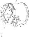
- FIG. 3 shows a 3D view of the mold unit 8.
- the pipe jacket 32 with its fastening flange 34 and its collar 36 as well as the upper edge of the mold pipe 24 and a part of the mold cavity 28 are visible, whereas the reinforcement plates 30 are covered by the pipe jacket 32.
- the tube jacket 32 includes a coolant inlet 40 and a coolant outlet 42 for each reinforcement plate 30.
- Three of the four coolant inlets 40 are arranged on the mounting flange 34 of the tube jacket 32, while the other coolant inlet 40 is arranged laterally on the pipe jacket 32.
- three of the four coolant outlets 42 are arranged on the fastening flange 34 , while the other coolant outlet 42 is arranged on the side of the pipe jacket 32 .
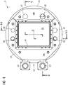
- FIG 4 shows a plan view of the mold unit 8.
- the upper edge of the mold tube 24 and its mold cavity 28 can also be seen in this figure.
- the fastening flange 34 and a part of the collar 36 of the pipe jacket 32 as well as the coolant inlets 40 and the coolant outlets 42 are visible.
- FIG 4 a first kinking section surface VV and a second kinking section surface VI-VI are shown.
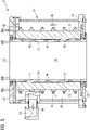
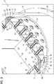
- FIG 5 shows a section through the mold unit 8 along the cutting surface VV FIG 4 and 6 shows a section through the mold unit 8 along the interface VI-VI FIG 4 .
- the mold unit 8 Between its reinforcement plates 30 and its mold tube 24, the mold unit 8 has a coolant guide gap 44 for guiding a coolant 46 on.
- the coolant-guiding gaps 44 are each laterally delimited by one of the reinforcement plates 30 and one of the side walls 26 of the mold tube 24 .
- the coolant 46 is shown symbolically in the form of arrows, the directions of the arrows representing the flow direction of the coolant 46 in each case.
- the coolant 46 flows into the mold unit 8 via the coolant inlets 40 of the pipe jacket 32 .
- the coolant 46 flows downward.
- the coolant 46 is deflected at the end plate 38 .
- the coolant 46 then flows upwards in the coolant guide gaps 44 and then exits the mold unit 8 via the coolant outlets 42 of the tube jacket 32 .
- the cavity 48 between the tube jacket 32 and the reinforcement plates 30 forms a coolant feed, while the coolant guide gaps 44 form a coolant return.
- FIG 7 shows a 3D view of the previously mentioned mold tube 24 of the mold unit 8. In this figure, all four side walls 26 of the mold tube 24 and its corner areas 50 are visible.
- FIG 7 Several threaded inserts 52 of the mold unit 8 that are provided with an internal and external thread can be seen, which are screwed into recesses 54 in the side walls 26 of the mold tube 24 and protrude from the recesses 54 (cf. 8 and 9 ).
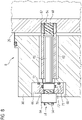
- the connecting element 56 is designed as an expansion bolt and has a threaded section 58 at each of its two ends and an unthreaded shank section 60 arranged between them, the length of the shank section 60 corresponding to approximately 60% of the overall length of the connecting element 56 .
- the shank portion 60 has a smaller diameter than each of the two threaded portions 58.
- the diameter of the shank portion 60 can be the same as the diameter of the respective threaded portion 58.
- the connecting element 56 is in one of the aforementioned threaded inserts 52, which is inserted into a recess 54 of the illustrated side wall 26 of the mold tube 24 is screwed.
- a part of the connecting element 56 is surrounded by a clamping sleeve 62 which abuts said threaded insert 52 on the face side. Furthermore, the connecting element 56 is secured by means of a nut 64 .
- a washer 66 is disposed between the nut 64 and the backing plate 30 shown. In the present embodiment, the washer 66 is fully recessed in a recess 68 of the reinforcing plate 30, while the nut 64 is partially recessed in this recess 68.
- the washer 66 has two annular grooves 70, in each of which a sealing ring 72, preferably an elastomer sealing ring, is inserted, one of these two sealing rings 72 bearing against the reinforcement plate 30 and the other of these two sealing rings 72 bearing on the connecting element 56.
- a sealing ring 72 preferably an elastomer sealing ring
- Each of the reinforcement plates 30 of the mold unit 8 is attached to the associated side wall 26 of the mold tube 24 with the aid of a plurality of connecting elements 56 of the type described above (cf. 9 ).
- the above statements in context with the connecting element 56 8 apply correspondingly to the other connecting elements 56 of the mold unit 8.
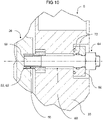
- FIG. 10 shows an alternative sectional view of a part of the mold unit 8 8 .
- the threaded extension 52 is designed in one piece with the clamping sleeve 62.
- the shank portion 60 has the same outside diameter as the threaded portion 58 .
- the length of the clamping sleeve 62 is only approximately 20% of the length of the connecting element 56.
- FIG. 9 shows a cross section of the mold unit 8. In this figure, part of the mold tube 24, parts of the reinforcement plates 30 and part of the tube jacket 32 are visible. In addition, 9 among other things, several of the previously mentioned connecting elements 56 as well as the nuts 64, by means of which the connecting elements 56 are secured, can be seen.
- the reinforcement plates 30 are each fastened to the mold tube 24 by means of a plurality of connecting elements 56, but the reinforcement plates 30 are not connected to one another by screw connections at the corner regions 50 of the mold tube 24.
- Adjacent reinforcing plates 30 are sealed against one another at the corner regions 50 of the mold tube 24 by means of a first sealing element 74 and a second sealing element 76 .
- These sealing elements 74, 76 separate the coolant flow of the mold unit 8 from the coolant return of the mold unit 8 at the corner areas 50 of the mold tube 24.
- the respective first sealing element 74 is an elastic sealing cord which is inserted into a groove 78 of one of the adjacent reinforcement plates 30, whereas the respective second sealing element 76 is an elongate, curved sealing plate which engages with its longitudinal edges in two grooves 80 of the adjacent reinforcement plates 30 .
- those reinforcing plates 30 which are attached to the narrower side walls 26 of the mold tube 24 have a wall thickness d 1 which is smaller than the wall thickness d 2 of those reinforcing plates 30 which are attached to the wider side walls 26 of the mold tube 24.
- the mold tube 24 has a wall thickness d 0 that is smaller than the aforementioned wall thicknesses d 1 , d 2 .
- the wall thickness d 0 of the mold tube 26 is approximately 24 mm, while the wall thickness d 1 of the reinforcement plates 30 fastened to the narrower side walls 26 of the mold tube 24 is approximately 55 mm and the wall thickness d 2 of those on the wider side walls 26 of the mold tube 24 attached reinforcing plates 30 is approximately 110 mm, with other values for the wall thicknesses d 0 , d 1 , d 2 also being possible in principle.
- Each of the reinforcing plates 30 has a rear side 82 facing the mold tube 24 and a front side 84 facing away from the mold tube 24 .
- the reinforcement plates 30 fastened to the wider side walls 26 of the mold tube 24 also each have two front edge surfaces connecting their front side 84 and their rear side 82 to one another 86, which are partially covered by the reinforcement plates 30 fastened to the narrower side walls 26 of the mold tube 24.
- the two reinforcing plates 30 attached to the wider side walls 26 of the mold tube 24 are partially arranged between the two reinforcing plates 30 attached to the narrower side walls 26 of the mold tube 24 .
Description
Die Erfindung betrifft eine Kokilleneinheit zum Stranggießen von Metallprodukten, insbesondere zum Stranggießen von Vorblöcken. Des Weiteren betrifft die Erfindung eine Stranggießanlage.The invention relates to a mold unit for the continuous casting of metal products, in particular for the continuous casting of blooms. Furthermore, the invention relates to a continuous casting plant.
Bei Kokillen zum Stranggießen von Metallprodukten, wie zum Beispiel Vorblöcken, wird zwischen sogenannten Plattenkokillen und sogenannten Rohrkokillen unterschieden. Plattenkokillen umfassen mehrere separate, einander kontaktierende Kokillenplatten, die gemeinsam eine Gussform mit einer polygonalen, insbesondere rechteckigen Querschnittsform bilden. Rohrkokillen hingegen umfassen ein Kokillenrohr, welches eine Gussform mit einer runden, insbesondere kreisförmigen Querschnittsform oder einer polygonalen, insbesondere rechteckigen Querschnittsform bildet.In molds for the continuous casting of metal products, such as blooms, a distinction is made between so-called plate molds and so-called tube molds. Plate molds comprise a number of separate mold plates which are in contact with one another and which together form a mold with a polygonal, in particular rectangular, cross-sectional shape. Tube moulds, on the other hand, comprise a mold tube which forms a mold with a round, in particular circular, cross-sectional shape or a polygonal, in particular rectangular, cross-sectional shape.
Ein Vorteil einer Plattenkokille ist, dass ihre Kokillenplatten derart gelagert werden können, dass ein Abstand zwischen einander gegenüberliegenden Kokillenplatten verstellt werden kann, sodass mit der Plattenkokille Metallprodukte unterschiedlicher Formate gegossen werden können. Ein weiterer Vorteil einer Plattenkokille ist, dass beschädigte oder verschlissene Kokillenplatten gezielt nachbearbeitet oder ausgetauscht werden können. Nachteilig bei einer Plattenkokille ist jedoch, dass an deren Eckbereichen Spalte zwischen benachbarten Kokillenplatten vorhanden sein können, in welche Fremdkörper, wie zum Beispiel Reste von (verflüssigtem) Gießpulver, eindringen können und/oder flüssiges Metall eindringen kann. Hierbei können scharfkantige Grate, sogenannte Finnen, am Strang entstehen. Beim Ausfördern eines Strangs aus einer Plattenkokille unterliegen Finnen einer höheren Haftreibung als die restliche Oberfläche des Stangs. Dadurch entstehen mechanische Spannungen, die zum Reißen einer sich bildenden Strangschale führen können.An advantage of a plate mold is that its mold plates can be stored in such a way that a distance between opposing mold plates can be adjusted, so that metal products of different formats can be cast with the plate mold. Another advantage of a plate mold is that damaged or worn mold plates can be reworked or replaced in a targeted manner. A disadvantage of a plate mold, however, is that there may be gaps between adjacent mold plates at the corner areas thereof, into which foreign bodies, such as residues of (liquefied) casting powder, can penetrate and/or liquid metal can penetrate. This can result in sharp-edged burrs, so-called fins, on the strand. When a strand is extracted from a plate mold, fins are subject to higher static friction than the remaining surface of the strand. This creates mechanical stresses that can lead to the tearing of a strand shell that is being formed.
An den Eckbereichen einer Rohrkokille (mit polygonaler Querschnittsform) tritt das zuvor beschriebene Problem normalerweise nicht auf, da die Seitenwände des Kokillenrohrs normalerweise einstückig miteinander ausgebildet sind. Allerdings kann mit einer einstückig ausgebildeten Rohrkokille nur ein einziges Format eines Metallprodukts gegossen werden. Zudem ist es bei einer einstückig ausgebildeten Rohrkokille nicht möglich, gezielt einzelne Seitenwände auszutauschen, wenn diese beschädigt oder verschlissen sind.The problem described above does not normally occur at the corner regions of a tube mold (with a polygonal cross-sectional shape), since the side walls of the mold tube are usually formed in one piece with one another. However, only a single format of a metal product can be cast with a one-piece tubular mold. In addition, with a one-piece tubular mold, it is not possible to specifically replace individual side walls if they are damaged or worn.
Bisher werden Rohrkokillen überwiegend zum Stranggießen kleinformatiger Metallprodukte verwendet. Zum Stranggießen großformatiger Metallprodukte verwendet man bisher üblicherweise Plattenkokillen. Jedoch kommen beim Stranggießen großformatiger Metallprodukte neuerdings vermehrt Rohrkokillen zum Einsatz, da bei einer Rohrkokille das Problem der Entstehung von Finnen üblicherweise nicht auftritt.Until now, tube molds have mainly been used for the continuous casting of small-sized metal products. Up to now, plate molds have been used for the continuous casting of large-format metal products. Recently, however, in the continuous casting of large-sized metal products, tube molds have been increasingly used because a tube mold does not usually have the problem of generation of fins.
Bei einer Rohrkokille, die zum Stranggießen großformatiger Metallprodukte verwendet werden soll, ist darauf zu achten, dass die Wandstärke des Kokillenrohrs nicht zu groß gewählt wird, damit zum Zwecke der Wärmeabführung an ein Kühlmittel ein hinreichend guter Wärmedurchgang durch das Kokillenrohr gewährleistet werden kann. Eine geringe Wandstärke des Kokillenrohrs hat jedoch den Nachteil, dass es aufgrund der hohen (Kühlmittel-)Drücke, die auf das Kokillenrohr wirken, gegebenenfalls zu Verformungen des Kokillenrohrs und folglich zu einer verkürzten Lebensdauer des Kokillenrohrs kommen kann.In the case of a tubular mold that is to be used for the continuous casting of large-format metal products, care must be taken to ensure that the wall thickness of the mold tube is not too great so that adequate heat transfer through the mold tube can be ensured for the purpose of heat dissipation to a coolant. However, a low wall thickness of the mold tube has the disadvantage that, due to the high (coolant) pressures acting on the mold tube, the mold tube may be deformed and consequently the life of the mold tube may be shortened.
Im Stand der Technik wird der zuvor genannte Nachteil einer geringen Wandstärke des Kokillenrohrs, dadurch kompensiert, dass außen am Kokillenrohr mehrere Verstärkungsplatten befestigt werden, welche der Kokille eine hinreichend große Steifigkeit verleihen.In the prior art, the above-mentioned disadvantage of a small wall thickness of the mold tube is compensated for by several reinforcement plates being fastened to the outside of the mold tube, which give the mold a sufficiently high level of rigidity.
Aus der
Eine Aufgabe der Erfindung ist es, zu ermöglichen, dass eine Kokilleneinheit, die ein Kokillenrohr mit einer polygonalen äußeren Querschnittsform aufweist, bzw. eine mit einer solchen Kokilleneinheit ausgestattete Stranggießanlage eine hohe Lebensdauer erreicht.An object of the invention is to enable a mold unit that has a mold tube with a polygonal outer cross-sectional shape, or a continuous casting plant equipped with such a mold unit, to achieve a long service life.
Diese Aufgabe wird erfindungsgemäß gelöst durch eine Kokilleneinheit nach Anspruch 1 sowie durch eine Stranggießanlage nach Anspruch 15.This object is achieved according to the invention by a mold unit according to claim 1 and by a continuous casting plant according to claim 15.
Bevorzugte Ausgestaltungen der Erfindung sind in den weiteren Patentansprüchen sowie in der nachfolgenden Beschreibung angegeben.Preferred configurations of the invention are specified in the further patent claims and in the following description.
Die erfindungsgemäße Kokilleneinheit zum Stranggießen von Metallprodukten, insbesondere zum Stranggießen von Vorblöcken, umfasst ein Kokillenrohr mit einer polygonalen äußeren Querschnittsform, welches mehrere Eckbereiche aufweist, und mehrere separate Verstärkungsplatten, die außen am Kokillenrohr befestigt sind und gemeinsam das Kokillenrohr umschließen, wobei zwischen jeder der Verstärkungsplatten und dem Kokillenrohr jeweils ein Kühlmittelführungsspalt zum Führen eines Kühlmittels ausgebildet ist. Ferner sind bei der erfindungsgemäßen Kokilleneinheit die Verstärkungsplatten an den Eckbereichen des Kokillenrohrs nicht durch Schraubverbindungen miteinander verbunden. Mit anderen Worten, bei der erfindungsgemäßen Kokilleneinheit sind die Verstärkungsplatten an den Eckbereichen des Kokillenrohrs nicht miteinander verschraubt.The mold unit according to the invention for the continuous casting of metal products, in particular for the continuous casting of blooms, comprises a mold tube with a polygonal outer cross-sectional shape, which has several corner areas, and several separate reinforcing plates, which are attached to the outside of the mold tube and together enclose the mold tube, with between each of the reinforcing plates and a coolant guide gap for guiding a coolant is formed in each case in the mold tube. Furthermore, in the case of the mold unit according to the invention, the reinforcing plates at the corner regions of the mold tube are not connected to one another by screw connections. In other words, in the case of the mold unit according to the invention, the reinforcing plates are not screwed together at the corner areas of the mold tube.
Konkret gibt es nämlich keinen direkten Kontakt zwischen den Verstärkungsplatten. Ein etwaiges Dichtelement bzw. mehrere Dichtelemente zwischen zwei aneinander angrenzenden Verstärkungsplatten behindern die thermische Ausdehnung der Verstärkungsplatten nicht oder nur unwesentlich, da das Dichtelement elastisch verformbar und dessen Steifigkeit sehr niedrig ist. Im Vergleich zur Steifigkeit der Verstärkungsplatten ist die Steifigkeit der Dichtelemente vernachlässigbar gering.Specifically, there is no direct contact between the reinforcement plates. A possible sealing element or a plurality of sealing elements between two mutually adjoining reinforcement plates does not impede the thermal expansion of the reinforcement plates or only insignificantly, since the sealing element is elastically deformable and its rigidity is very low. Compared to the rigidity of the reinforcement plates, the rigidity of the sealing elements is negligible.
Die Erfindung beruht auf der Erkenntnis, dass es im Betrieb der Kokilleneinheit zu einer thermischen Ausdehnung des Kokillenrohrs sowie der Verstärkungsplatten kommt.The invention is based on the finding that thermal expansion of the mold tube and the reinforcing plates occurs during operation of the mold unit.
Wenn die Verstärkungsplatten an den Eckbereichen des Kokillenrohrs miteinander verschraubt sind, wie es beispielsweise in der
Da bei der Erfindung die Verstärkungsplatten an den Eckbereichen des Kokillenrohrs nicht miteinander verschraubt sind, können die Verstärkungsplatten an den Eckbereichen des Kokillenrohrs größere Wärmebewegungen relativ zueinander ausführen. Dadurch kann, insbesondere an den Eckbereichen des Kokillenrohrs, das Auftreten großer mechanischer Spannungen vermieden werden. Auf diese Weise können eine größere Lebensdauer der Kokilleneinheit und folglich auch eine größere Lebensdauer einer mit einer solchen Kokilleneinheit ausgestatteten Stranggießanlage erreicht werden.Since the reinforcing plates in the corner areas of the mold tube are not screwed together in the invention, the reinforcing plates in the corner areas of the mold tube can perform greater thermal movements relative to one another. As a result, the occurrence of large mechanical stresses can be avoided, particularly in the corner areas of the mold tube. In this way, a longer service life of the mold unit and consequently also a longer service life of a continuous casting plant equipped with such a mold unit can be achieved.
Vorteilhafterweise sind die Verstärkungsplatten an den Eckbereichen des Kokillenrohrs nicht stoffschlüssig miteinander verbunden, sodass die Verstärkungsplatten auch nicht durch eine stoffschlüssige Verbindung an einer thermischen Ausdehnung gehindert werden.Advantageously, the reinforcement plates are not bonded to one another in the corner areas of the mold tube, so that the reinforcement plates do not penetrate either a material connection can be prevented from thermal expansion.
Vorliegend ist der Begriff "polygonal" nicht notwendigerweise im streng mathematischen bzw. geometrischen Sinne zu verstehen. Im Sinne der Erfindung kann unter einer "polygonalen" (Querschnitts-)Form, wie zum Beispiel einer rechteckigen (Querschnitts-)Form, insbesondere eine (Querschnitts-)Form mit abgerundeten Ecken aufgefasst werden.In the present case, the term "polygonal" is not necessarily to be understood in a strictly mathematical or geometric sense. For the purposes of the invention, a “polygonal” (cross-sectional) shape, such as a rectangular (cross-sectional) shape, can be understood to mean, in particular, a (cross-sectional) shape with rounded corners.
Bei dem Kokillenrohr der Kokilleneinheit handelt es sich vorliegend um eine Gussform, welche mehrere Seitenwände aufweist, die einstückig miteinander ausgebildet sind.In the present case, the mold tube of the mold unit is a casting mold which has a plurality of side walls which are formed in one piece with one another.
In bevorzugter Weise ist das Kokillenrohr ein Kupferrohr. Das heißt, das Kokillenrohr ist vorzugsweise aus Kupfer oder einer Kupferlegierung gefertigt. Dadurch kann eine hohe Wärmeleitfähigkeit des Kokillenrohrs sichergestellt werden. Die zuvor erwähnten Verstärkungsplatten können beispielsweise aus rostfreiem Stahl, beispielsweise aus der Stahlsorte WNr. 1.4301, gefertigt sein.The mold tube is preferably a copper tube. This means that the mold tube is preferably made of copper or a copper alloy. This ensures a high thermal conductivity of the mold tube. The aforementioned reinforcing plates can be made, for example, from stainless steel, for example steel grade WNr. 1.4301.
Dadurch, dass bei der Erfindung zwischen jeder der Verstärkungsplatten und dem Kokillenrohr jeweils ein Kühlmittelführungsspalt zum Führen eines Kühlmittels ausgebildet ist, kann auf einen sogenannten Wasserleitmantel zum Führen eines Kühlmittels verzichtet werden. Stattdessen können die Verstärkungsplatten die Funktion eines Wasserleitmantels übernehmen. Dies ermöglicht eine aufwandsgünstige Herstellung der Kokilleneinheit, da auf eine aufwändige Fertigung eines Wasserleitmantels verzichtet werden kann.Due to the fact that in the invention between each of the reinforcement plates and the mold pipe a coolant guide gap for guiding a coolant is formed in each case, a so-called water-conducting jacket for guiding a coolant can be dispensed with. Instead, the reinforcement plates can assume the function of a water-conducting jacket. This enables the mold unit to be produced at low cost, since there is no need for a complex production of a water-conducting jacket.
Die zuvor erwähnten Kühlmittelführungsspalte sind vorzugsweise jeweils durch eine der Verstärkungsplatten und eine der Seitenwände des Kokillenrohrs seitlich begrenzt.The aforementioned coolant-guiding gaps are preferably each laterally delimited by one of the reinforcement plates and one of the side walls of the mold tube.
Vorteilhafterweise sind das Kokillenrohr und die Verstärkungsplatten an allen Stellen voneinander beabstandet. Mit anderen Worten, das Kokillenrohr und die Verstärkungsplatten sind vorteilhafterweise nicht miteinander in Kontakt, sondern an allen Stellen kontaktlos zueinander angeordnet. Dadurch kann vermieden werden, dass Wärme direkt vom Kokillenrohr an die Verstärkungsplatten geleitet wird. Außerdem kann auf diese Weise über eine vergleichsweise große Fläche der Verstärkungsplatten sowie über eine vergleichsweise große Fläche des Kokillenrohrs Wärme an das Kühlmittel abgegeben werden, wodurch mithilfe des Kühlmittels eine besonders starke Kühlwirkung erreicht werden kann.Advantageously, the mold tube and the reinforcing plates are spaced apart from each other at all points. With In other words, the mold tube and the reinforcing plates are advantageously not in contact with one another, but are arranged without contact with one another at all points. This can prevent heat from being conducted directly from the mold tube to the reinforcement plates. In addition, in this way heat can be given off to the coolant over a comparatively large area of the reinforcement plates and over a comparatively large area of the mold tube, as a result of which a particularly strong cooling effect can be achieved with the aid of the coolant.
Bei einer bevorzugten Ausgestaltung der Erfindung hat das Kokillenrohr einen Formhohlraum, der im Querschnitt des Kokillenrohrs eine rechteckige Form, insbesondere eine rechteckige Form mit abgerundeten oder vorgefasten Ecken, aufweist.In a preferred embodiment of the invention, the mold tube has a mold cavity which, in the cross section of the mold tube, has a rectangular shape, in particular a rectangular shape with rounded or pre-chamfered corners.
Des Weiteren ist es bevorzugt, wenn besagte rechteckige Form des Formhohlraums eine Länge von mindestens 280 mm, insbesondere mindestens 320 mm, und/oder eine Breite von mindestens 240 mm, insbesondere mindestens 280 mm, aufweist.Furthermore, it is preferred if said rectangular shape of the mold cavity has a length of at least 280 mm, in particular at least 320 mm, and/or a width of at least 240 mm, in particular at least 280 mm.
Ferner kann der Formhohlraum des Kokillenrohrs gebogen ausgebildet sein. Das heißt, die Kokilleneinheit kann eine sogenannte Bogenkokille sein. Alternativ kann der Formhohlraum gerade ausgebildet sein.Furthermore, the mold cavity of the mold tube can be curved. That is, the mold unit can be a so-called curved mold. Alternatively, the mold cavity can be straight.
Weiter ist es vorteilhaft, wenn das Kokillenrohr eine Wandstärke von höchstens 35 mm, vorzugsweise höchstens 30 mm, aufweist. Dies ermöglicht zum einen eine kostengünstigere Herstellung des Kokillenrohrs, da zur Herstellung des Kokillenrohrs vergleichsweise wenig Material benötigt wird. Zum anderen lässt sich dadurch ein guter Wärmedurchgang durch das Kokillenrohr erreichen, sodass mithilfe des Kühlmittels eine starke Kühlwirkung an der zu kühlenden Metallschmelze erreicht werden kann.It is also advantageous if the mold tube has a wall thickness of at most 35 mm, preferably at most 30 mm. On the one hand, this enables the mold tube to be produced more cost-effectively, since comparatively little material is required to produce the mold tube. On the other hand, good heat transfer can be achieved through the mold tube, so that the coolant can be used to achieve a strong cooling effect on the molten metal to be cooled.
Die Wandstärke des Kokillenrohrs kann über das gesamte Kokillenrohr hinweg konstant sein. Alternativ kann das Kokillenrohr unterschiedliche Wandstärken aufweisen. Im letztgenannten Fall kann die Formulierung, dass das Kokillenrohr eine Wandstärke von höchstens 35 mm bzw. höchstens 30 mm, aufweist, so verstanden werden, dass das Kokillenrohr an seiner/seinen dicksten Stelle/-n die Wandstärke von höchstens 35 mm bzw. höchstens 30 mm aufweist.The wall thickness of the mold tube can be constant over the entire mold tube. Alternatively, the mold tube have different wall thicknesses. In the latter case, the wording that the mold tube has a wall thickness of at most 35 mm or at most 30 mm can be understood to mean that the mold tube has a wall thickness of at most 35 mm or at most 30 mm at its thickest point(s). mm.
Das Kokillenrohr kann beispielsweise eine rechteckige äußere Querschnittsform aufweisen. In diesem Fall sind zweckmäßigerweise vier separate Verstärkungsplatten außen am Kokillenrohr befestigt. Das heißt, bei den zuvor erwähnten mehreren Verstärkungsplatten kann es sich insbesondere um vier Verstärkungsplatten handeln.The mold tube can, for example, have a rectangular external cross-sectional shape. In this case, four separate reinforcement plates are expediently attached to the outside of the mold tube. That is, the aforementioned multiple reinforcing plates may be four reinforcing plates in particular.
In bevorzugter Weise werden die stirnseitigen Randflächen von zwei der Verstärkungsplatten zumindest teilweise durch die beiden anderen Verstärkungsplatten abgedeckt. Anders formuliert, vorzugsweise sind zwei der Verstärkungsplatten zum Teil zwischen den anderen beiden Verstärkungsplatten angeordnet. Durch eine solche Anordnung der Verstärkungsplatten werden vergleichsweise große Wärmebewegungen der beiden verdeckenden Verstärkungsplatten zugelassen, da sich die verdeckenden Verstärkungsplatten thermisch ausdehnen können, ohne dabei stirnseitig an die anderen beiden Verstärkungsplatten anzustoßen.In a preferred manner, the end faces of two of the reinforcement plates are at least partially covered by the other two reinforcement plates. Stated another way, preferably two of the reinforcing plates are partially located between the other two reinforcing plates. Such an arrangement of the reinforcing plates permits comparatively large thermal movements of the two covering reinforcing plates, since the covering reinforcing plates can expand thermally without hitting the other two reinforcing plates at the ends.
Zwei der vier Verstärkungsplatten können schmaler ausgeführt sein als die anderen beiden Verstärkungsplatten. Vorzugsweise haben die beiden breiteren Verstärkungsplatten eine größere maximale Wandstärke als die beiden schmaleren Verstärkungsplatten. Dadurch können die breiteren Verstärkungsplatten größeren Kräften standhalten als die schmaleren Verstärkungsplatten.Two of the four reinforcement plates can be made narrower than the other two reinforcement plates. Preferably, the two wider reinforcement plates have a greater maximum wall thickness than the two narrower reinforcement plates. This allows the wider backing plates to withstand greater forces than the narrower backing plates.
Bei einer bevorzugten Ausführungsform der Erfindung weist die Kokilleneinheit eine Mehrzahl von Verbindungselementen auf, mittels welcher die Verstärkungsplatten am Kokillenrohr befestigt sind. Die Verbindungselemente können beispielsweise jeweils ein oder mehrere Gewindeabschnitte aufweisen.In a preferred embodiment of the invention, the mold unit has a plurality of connecting elements, by means of which the reinforcing plates are attached to the mold tube are. The connecting elements can each have one or more threaded sections, for example.
Unter einem Gewindeabschnitt eines Verbindungselements ist vorliegend ein mit einem Gewinde versehener Abschnitt des Verbindungselements zu verstehen.A threaded section of a connecting element is to be understood here as a section of the connecting element provided with a thread.
Darüber hinaus kann die Kokilleneinheit eine Mehrzahl von Gewindeeinsätzen aufweisen, die in Aussparungen des Kokillenrohrs eingesetzt sind. Vorzugsweise sind die Verbindungselemente in die Gewindeeinsätze eingeschraubt. Die Gewindeeinsätze ermöglichen eine einfache und schnelle Montage der Verstärkungsplatten am Kokillenrohr unter Verwendung von Verbindungselementen.In addition, the mold unit can have a plurality of threaded inserts that are inserted into recesses in the mold tube. The connecting elements are preferably screwed into the threaded inserts. The threaded inserts enable easy and quick assembly of the reinforcement plates on the mold tube using fasteners.
Der Ausdruck "eingesetzt" ist vorliegend nicht notwendigerweise so zu verstehen, dass der jeweilige Gewindeeinsatz vollständig in einer Aussparung angeordnet sein muss. In einer bevorzugten Ausführungsform der Erfindung steht der jeweilige Gewindeeinsatz aus der Aussparung heraus.The expression "inserted" is not necessarily to be understood here in such a way that the respective thread insert has to be arranged completely in a recess. In a preferred embodiment of the invention, the respective threaded insert protrudes from the recess.
Vorteilhafterweise sind die Verbindungselemente als Dehnbolzen ausgebildet. Ein Vorteil von als Dehnbolzen ausgebildeten Verbindungselementen ist, dass sie eine Wärmebewegung der Verstärkungsplatten relativ zum Kokillenrohr zulassen, ohne dass es dabei zu einer zu starken Spannung der Verbindungselemente kommt, die gegebenenfalls zu einer plastischen und/oder trennenden Verformung der Verbindungselemente führen könnte. Das jeweilige Verbindungselement weist vorzugsweise einen gewindelosen Schaftabschnitt auf. Dessen Durchmesser kann insbesondere kleiner sein als der Durchmesser des Gewindeabschnitts bzw. der Gewindeabschnitte des jeweiligen Verbindungselements. Alternativ kann der Durchmesser des Schaftabschnitts des jeweiligen Verbindungselements gleich oder annähernd gleich groß sein wie der Durchmesser des Gewindeabschnitts bzw. der Gewindeabschnitte. Die Länge des Schaftabschnitts kann zum Beispiel zwischen 50 mm und 100 mm betragen. Vorzugsweise entspricht die Länge des Schaftabschnitts mindestens 50% der Gesamtlänge des Verbindungselements.The connecting elements are advantageously designed as expansion bolts. An advantage of connecting elements designed as expansion bolts is that they allow thermal movement of the reinforcement plates relative to the mold tube without the connecting elements being subjected to excessive tension, which could possibly lead to plastic and/or separating deformation of the connecting elements. The respective connecting element preferably has an unthreaded shank section. In particular, its diameter can be smaller than the diameter of the threaded section or the threaded sections of the respective connecting element. Alternatively, the diameter of the shank portion of the respective connecting element can be the same or approximately the same size as the diameter of the threaded portion or threaded portions. The length of the shaft section can be between 50 mm and 100 mm, for example. The length of the shank section preferably corresponds to at least 50% of the total length of the connecting element.
Des Weiteren kann die Kokilleneinheit eine Mehrzahl von Klemmhülsen umfassen, die jeweils einen Teil eines der Verbindungselemente, insbesondere den gewindelosen Schaftabschnitt, umgeben. Vorzugsweise sind die Klemmhülsen jeweils zwischen einer der Verstärkungsplatten und dem Kokillenrohr verspannt.Furthermore, the mold unit can comprise a plurality of clamping sleeves, each of which surrounds a part of one of the connecting elements, in particular the unthreaded shank section. Preferably, the clamping sleeves are each braced between one of the reinforcement plates and the mold tube.
Die Klemmhülsen können stirnseitig an den Gewindeeinsätzen anliegen oder eine Klemmhülse mit einem Gewindeeinsatz einen einzigen Bauteil ausbilden. Wenn ein Gewindeeinsatz aus einer Aussparung des Kokillenrohrs heraussteht, kann in diesem Fall erreicht werden, dass die Klemmhülse eine Kraft auf den Gewindeeinsatz, nicht jedoch unmittelbar auf die Seitenwand des Kokillenrohrs überträgt.The clamping sleeves can be in contact with the threaded inserts on the face side, or a clamping sleeve with a threaded insert can form a single component. If a threaded insert protrudes from a recess in the mold tube, it can be achieved in this case that the clamping sleeve transmits a force to the threaded insert, but not directly to the side wall of the mold tube.
Ferner ist es zweckmäßig, wenn die Kokilleneinheit eine Mehrzahl von Muttern aufweist, mittels welcher die Verbindungselemente gesichert sind. Gegebenenfalls kann die Kokilleneinheit eine Mehrzahl von Unterlegscheiben aufweisen, an welchen die Muttern anliegen. Optional kann die Kokilleneinheit außerdem zwischen der jeweiligen Unterlegscheiben und der jeweiligen Mutter ein oder mehrere Federelemente, wie zum Beispiel eine oder mehrere Tellerfedern, aufweisen.Furthermore, it is expedient if the mold unit has a plurality of nuts, by means of which the connecting elements are secured. If necessary, the mold unit can have a plurality of washers against which the nuts rest. Optionally, the mold unit can also have one or more spring elements, such as one or more plate springs, between the respective washers and the respective nut.
Vorteilhafterweise sind benachbarte Verstärkungsplatten an den Eckbereichen des Kokillenrohrs jeweils mittels eines oder mehrerer Dichtelemente gegeneinander abgedichtet. In bevorzugter Weise sind benachbarte Verstärkungsplatten an den Eckbereichen des Kokillenrohrs jeweils mithilfe eines ersten Dichtelements und eines zweiten Dichtelements, welches vom ersten Dichtelement verschieden ist, gegeneinander abgedichtet. Dadurch kann eine besonders gute Dichtigkeit an den Eckbereichen des Kokillenrohrs erreicht werden.Advantageously, adjacent reinforcement plates are sealed against each other in the corner regions of the mold tube by means of one or more sealing elements. Adjacent reinforcing plates in the corner regions of the mold tube are preferably sealed against one another with the aid of a first sealing element and a second sealing element, which is different from the first sealing element. As a result, a particularly good seal can be achieved in the corner areas of the mold tube.
Das erste Dichtelement kann zum Beispiel eine elastische Dichtschnur sein, welche in eine Nut, insbesondere in eine in Höhenrichtung der Kokilleneinheit verlaufende Nut, einer der benachbarten Verstärkungsplatten eingesetzt ist. Bei dem zweiten Dichtelement kann es sich beispielsweise um ein längliches, gebogenes Abdichtblech handeln, welches mit seinen Längsrändern in zwei Nuten, insbesondere in zwei in Höhenrichtung der Kokilleneinheit verlaufende Nuten, der benachbarten Verstärkungsplatten eingreift.The first sealing element can be, for example, an elastic sealing cord, which is inserted into a groove, in particular into a groove running in the vertical direction of the mold unit, of one of the adjacent reinforcing plates. The second sealing element can be, for example, an elongate, curved sealing plate, which engages with its longitudinal edges in two grooves, in particular in two grooves running in the vertical direction of the mold unit, of the adjacent reinforcing plates.
In dem Fall, dass benachbarte Verstärkungsplatten an den Eckbereichen des Kokillenrohrs jeweils mit nur einem Dichtelement abgedichtet sind, kann es sich bei dem jeweiligen Dichtelement beispielsweise um ein Dichtelement vom Typ des zuvor erwähnten ersten Dichtelements oder des zuvor erwähnten zweiten Dichtelements handeln.In the event that adjacent reinforcement plates are each sealed at the corner regions of the mold tube with only one sealing element, the respective sealing element can be, for example, a sealing element of the type of the aforementioned first sealing element or the aforementioned second sealing element.
Vorzugsweise umfasst die Kokilleneinheit einen das Kokillenrohr und die Verstärkungsplatten umgebenden Rohrmantel. Der Rohrmantel weist vorteilhafterweise einen oder mehrere Kühlmitteleinlässe und/oder einen oder mehrere Kühlmittelauslässe auf. Insbesondere kann der Rohrmantel pro Verstärkungsplatte jeweils einen Kühlmitteleinlass und einen Kühlmittelauslass aufweisen. In dem bevorzugten Fall, dass die Kokilleneinheit vier Verstärkungsplatten umfasst, kann der Rohrmantel also insbesondere vier Kühlmitteleinlässe sowie vier Kühlmittelauslässe aufweisen.The mold unit preferably comprises a tube jacket surrounding the mold tube and the reinforcing plates. The tube jacket advantageously has one or more coolant inlets and/or one or more coolant outlets. In particular, the tube jacket can have a coolant inlet and a coolant outlet for each reinforcement plate. In the preferred case that the mold unit comprises four reinforcement plates, the pipe jacket can therefore have in particular four coolant inlets and four coolant outlets.
Weiter ist es vorteilhaft, wenn der jeweilige Kühlmitteleinlass und der jeweilige Kühlmittelauslass des Rohrmantels fluidleitend mit mindestens einem der Kühlmittelführungsspalte verbunden sind.It is also advantageous if the respective coolant inlet and the respective coolant outlet of the pipe jacket are connected to at least one of the coolant guide gaps in a fluid-conducting manner.
Bei einer bevorzugten Ausführungsvariante der Erfindung bildet einen Hohlraum zwischen den Verstärkungsplatten und dem Rohrmantel einen Kühlmittel-Vorlauf der Kokilleneinheit, während die Kühlmittelführungsspalte gemeinsam einen Kühlmittel-Rücklauf der Kokilleneinheit bilden. Alternativ kann der Hohlraum zwischen den Verstärkungsplatten und dem Rohrmantel einen Kühlmittel-Rücklauf der Kokilleneinheit bilden, während die Kühlmittelführungsspalte gemeinsam einen Kühlmittel-Vorlauf der Kokilleneinheit bilden.In a preferred embodiment of the invention, a cavity between the reinforcement plates and the pipe jacket forms a coolant feed for the mold unit, while the coolant guide gaps together form a coolant return for the mold unit. Alternatively, he can Cavity between the reinforcing plates and the pipe jacket form a coolant return of the mold unit, while the coolant guide column together form a coolant flow of the mold unit.
Vorteilhafterweise trennen die zuvor erwähnten Dichtelemente den Kühlmittel-Vorlauf vom Kühlmittel-Rücklauf an den Eckbereichen des Kokillenrohrs.Advantageously, the previously mentioned sealing elements separate the coolant flow from the coolant return at the corner areas of the mold tube.
Der Rohrmantel kann einen Befestigungsflansch zur Befestigung der Kokilleneinheit an einer Kokillenträgervorrichtung aufweisen. Besagter Befestigungsflansch ist vorzugsweise am oberen Ende des Rohrmantels angeordnet. Ferner kann vorgesehen sein, dass mindestens ein Kühlmitteleinlass des Rohrmantels im Befestigungsflansch angeordnet ist und/oder mindestens ein Kühlmittelauslass des Rohrmantels im Befestigungsflansch angeordnet ist.The pipe jacket can have a fastening flange for fastening the mold unit to a mold carrier device. Said mounting flange is preferably arranged at the upper end of the pipe shell. Furthermore, it can be provided that at least one coolant inlet of the pipe jacket is arranged in the fastening flange and/or at least one coolant outlet of the pipe jacket is arranged in the fastening flange.
Wie eingangs erwähnt, betrifft die Erfindung unter anderem eine Stranggießanlage.As mentioned at the outset, the invention relates, inter alia, to a continuous casting plant.
Die erfindungsgemäße Stranggießanlage ist mit einer erfindungsgemäßen Kokilleneinheit ausgestattet.The continuous casting plant according to the invention is equipped with a mold unit according to the invention.
Bei der Stranggießanlage kann es sich insbesondere um eine sogenannte Bogenstranggießanlage handeln. Alternativ kann die Stranggießanlage eine sogenannte Vertikalstranggießanlage sein.The continuous casting plant can in particular be a so-called curved continuous casting plant. Alternatively, the continuous casting plant can be a so-called vertical continuous casting plant.
Die bisher gegebene Beschreibung bevorzugter Ausgestaltungen der Erfindung enthält zahlreiche Merkmale, die in den einzelnen abhängigen Patentansprüchen teilweise zu mehreren zusammengefasst wiedergegeben sind. Diese Merkmale können jedoch auch einzeln betrachtet und zu sinnvollen weiteren Kombinationen zusammengefasst werden. Insbesondere sind diese Merkmale jeweils einzeln und in beliebiger geeigneter Kombination mit der erfindungsgemäßen Kokilleneinheit und der erfindungsgemäßen Stranggießanlage kombinierbar.The description given so far of preferred configurations of the invention contains numerous features, some of which are combined into several in the individual dependent patent claims. However, these features can also be considered individually and combined to form further meaningful combinations. In particular, these features can each be combined individually and in any suitable combination with the mold unit according to the invention and the continuous casting plant according to the invention.
Die oben beschriebenen Eigenschaften, Merkmale und Vorteile der Erfindung sowie die Art und Weise, wie diese erreicht werden, werden klarer und deutlicher verständlich im Zusammenhang mit der folgenden Beschreibung eines Ausführungsbeispiels der Erfindung, das im Zusammenhang mit den Figuren näher erläutert wird. Das Ausführungsbeispiel dient der Erläuterung der Erfindung und beschränkt die Erfindung nicht auf die darin angegebenen Kombinationen von Merkmalen, auch nicht in Bezug auf funktionale Merkmale. Außerdem können dazu geeignete Merkmale des Ausführungsbeispiels auch explizit isoliert betrachtet und mit einem beliebigen der Ansprüche kombiniert werden.The characteristics, features and advantages of the invention described above and the manner in which they are achieved will become clearer and more clearly understood in connection with the following description of an embodiment of the invention, which will be explained in more detail in connection with the figures. The exemplary embodiment serves to explain the invention and does not limit the invention to the combinations of features specified therein, not even in relation to functional features. In addition, suitable features of the exemplary embodiment can also be explicitly considered in isolation and combined with any of the claims.
Es zeigen:
- FIG 1
- eine schematische Darstellung einer Stranggießanlage mit einer Kokilleneinheit;
- FIG 2
- einen Längsschnitt der Kokilleneinheit aus
FIG 1 sowie eine Kokillenträgervorrichtung, an welcher die Kokilleneinheit befestigt ist; - FIG 3
- eine 3D-Ansicht der Kokilleneinheit;
- FIG 4
- eine Draufsicht der Kokilleneinheit;
- FIG 5
- einen Schnitt durch die Kokilleneinheit entlang der Schnittfläche V-V aus
FIG 4 ; - FIG 6
- einen Schnitt durch die Kokilleneinheit entlang der Schnittfläche VI-VI aus
FIG 4 ; - FIG 7
- eine 3D-Ansicht eines Kokillenrohrs der Kokilleneinheit;
- FIG 8
- eine Schnittdarstellung der Kokilleneinheit, in welcher ein Verbindungselement der Kokilleneinheit abgebildet ist;
- FIG 9
- einen Querschnitt der Kokilleneinheit;
- FIG 10
- eine alternative Schnittdarstellung eines Teils der Kokilleneinheit 8 zu
FIG 8 .
- FIG 1
- a schematic representation of a continuous casting plant with a mold unit;
- FIG 2
- a longitudinal section of the mold unit
FIG 1 and a mold support device to which the mold unit is attached; - 3
- a 3D view of the mold unit;
- FIG 4
- a plan view of the mold unit;
- 5
- a section through the mold unit along the cutting surface VV
FIG 4 ; - 6
- a section through the mold unit along the interface VI-VI
FIG 4 ; - FIG 7
- a 3D view of a mold tube of the mold unit;
- 8
- a sectional view of the mold unit, in which a connecting element of the mold unit is shown;
- 9
- a cross section of the mold unit;
- 10
- an alternative sectional view of part of the
mold unit 88 .
Die Stranggießanlage 2 umfasst einen Pfannendrehturm 4, in den zwei austauschbare Gießpfannen 6 eingesetzt sind, sowie eine Kokilleneinheit 8. Letztere ist an einer Kokillenträgervorrichtung 10 befestigt (vgl.
Außerdem umfasst die Stranggießanlage 2 ein Verteilerbecken 12 zum Aufnehmen einer Metallschmelze aus den Gießpfannen 6 und zum Weiterleiten der Metallschmelze zu der Kokilleneinheit 8. Des Weiteren verfügt die Stranggießanlage 2 über ein Strangführungssystem 14 mit einer figürlich nicht dargestellten Kühleinrichtung und mehreren Strangführungsrollen 16 sowie über eine Trennvorrichtung 18.In addition, the continuous casting plant 2 includes a
In den Gießpfannen 6 befindet sich eine Metallschmelze, beispielsweise flüssiger Stahl. Die Metallschmelze wird aus der jeweiligen Gießpfanne 6 in das Verteilerbecken 12 eingeleitet. Von dort wird die Metallschmelze über ein Auslassrohr 20 des Verteilerbeckens 12 in die Kokilleneinheit 8 eingeleitet.In the
Da durch die Kokilleneinheit 8 ein Kühlmittel, vorzugsweise Wasser, geleitet wird, kühlt die Metallschmelze an seinen Kontaktflächen mit der Kokilleneinheit 8 ab und erstarrt hierbei teilweise, sodass die Metallschmelze in Form eines Strangs 22 aus der Kokilleneinheit 8 austritt. Beim Austreten aus der Kokilleneinheit 8 hat der Strang 22 eine erstarrte Schale, während ein Großteil seines Querschnitts noch flüssig ist.Since a coolant, preferably water, is passed through the
Mithilfe der Strangführungsrollen 16 des Strangführungssystems 14 wird der aus der Kokilleneinheit 8 austretende Strang 22 abtransportiert und dabei entlang eines Bogens geführt. Im Strangführungssystem 14 wird der Strang 22 mithilfe der Kühleinrichtung des Strangführungssystems 14 weiter abgekühlt, sodass der Strang 22 erstarrt.With the aid of the
Mittels der Trennvorrichtung 18 wird der Strang 22 zum Zwecke seiner Weiterverarbeitung in mehrere Einzelstücke zerteilt und anschließend abtransportiert. Alternativ könnte der Strang 22 beispielsweise von einem oder mehreren Walzgerüsten direkt weiterverarbeitet werden, ohne vorher zerteilt zu werden.By means of the separating
Wie aus
Ferner weist der Formhohlraum 28 im vorliegenden Ausführungsbeispiel im Querschnitt des Kokillenrohrs 24 eine rechteckige Form mit abgerundeten Ecken sowie einer Länge L von 380 mm und einer Breite B von 280 mm auf (vgl.
Des Weiteren umfasst die Kokilleneinheit 8 vier separate Verstärkungsplatten 30, die außen am Kokillenrohr 24 befestigt sind und gemeinsam das Kokillenrohr 24 umschließen, wobei in
Darüber hinaus umfasst die Kokilleneinheit 8 einen das Kokillenrohr 24 und die Verstärkungsplatten 30 umgebenden, zylindrischen Rohrmantel 32. An seinem oberen Ende weist der Rohrmantel 32 einen Befestigungsflansch 34 auf, mittels welchem die Kokilleneinheit 8 an der Kokillenträgervorrichtung 10 befestigt ist. An seinem unteren Ende weist der Rohrmantel 32 einen umlaufenden Kragen 36 auf.In addition, the
Ferner weist die Kokilleneinheit 8 eine am Kragen 36 des Rohrmantels 32 befestigte Abschlussplatte 38 auf, mittels welcher am unteren Ende des Rohrmantels 32 eine Öffnung zwischen dem Rohrmantel 32 und dem Kokillenrohr 24 verschlossen ist.Furthermore, the
Der Rohrmantel 32 umfasst pro Verstärkungsplatte 30 jeweils einen Kühlmitteleinlass 40 sowie einen Kühlmittelauslass 42. Das heißt, der Rohrmantel 32 umfasst insgesamt vier Kühlmitteleinlässe 40 sowie vier Kühlmittelauslässe 42. Drei der vier Kühlmitteleinlässe 40 sind am Befestigungsflansch 34 des Rohrmantels 32 angeordnet, während der andere Kühlmitteleinlass 40 seitlich am Rohrmantel 32 angeordnet ist. Ebenfalls sind drei der vier Kühlmittelauslässe 42 am Befestigungsflansch 34 angeordnet, während der andere Kühlmittelauslass 42 seitlich am Rohrmantel 32 angeordnet ist.The
Ferner sind in
Sowohl in
Wie aus
Zwischen ihren Verstärkungsplatten 30 und ihrem Kokillenrohr 24 weist die Kokilleneinheit 8 jeweils einen Kühlmittelführungsspalt 44 zum Führen eines Kühlmittels 46 auf. Die Kühlmittelführungsspalte 44 sind jeweils durch eine der Verstärkungsplatten 30 und eine der Seitenwände 26 des Kokillenrohrs 24 seitlich begrenzt.Between its
In
Das Kühlmittel 46 strömt über die Kühlmitteleinlässe 40 des Rohrmantels 32 in die Kokilleneinheit 8 ein. In einem Hohlraum 48 zwischen dem Rohrmantel 32 und den Verstärkungsplatten 30 strömt das Kühlmittel 46 nach unten. An der Abschlussplatte 38 wird das Kühlmittel 46 umgelenkt. In den Kühlmittelführungsspalten 44 strömt das Kühlmittel 46 dann nach oben und tritt anschließend über die Kühlmittelauslässe 42 des Rohrmantels 32 aus der Kokilleneinheit 8 aus. Der Hohlraum 48 zwischen dem Rohrmantel 32 und den Verstärkungsplatten 30 bildet hierbei einen Kühlmittel-Vorlauf, während die Kühlmittelführungsspalte 44 einen Kühlmittel-Rücklauf bilden.The
Des Weiteren sind in
In
Das Verbindungselement 56 ist als Dehnbolzen ausgebildet und weist an seinen beiden Enden jeweils einen Gewindeabschnitt 58 sowie einen dazwischen angeordneten gewindelosen Schaftabschnitt 60 auf, wobei die Länge des Schaftabschnitts 60 circa 60% der Gesamtlänge des Verbindungselements 56 entspricht. Im vorliegenden Ausführungsbeispiel weist der Schaftabschnitt 60 einen geringeren Durchmesser auf als jeder der beiden Gewindeabschnitte 58. Alternativ kann der Durchmesser des Schaftabschnitts 60 gleich groß sein wie der Durchmesser des jeweiligen Gewindeabschnitts 58. Darüber hinaus ist das Verbindungselement 56 in einen der zur vorerwähnten Gewindeeinsätze 52, welcher in eine Aussparung 54 der abgebildeten Seitenwand 26 des Kokillenrohrs 24 eingesetzt ist, eingeschraubt.The connecting
Ein Teil des Verbindungselements 56 ist von einer Klemmhülse 62, die stirnseitig an besagtem Gewindeeinsatz 52 anliegt, umgeben. Ferner ist das Verbindungselement 56 mittels einer Mutter 64 gesichert. Zwischen der Mutter 64 und der abgebildeten Verstärkungsplatte 30 ist eine Unterlegscheibe 66 angeordnet. Im vorliegenden Ausführungsbeispiel ist die Unterlegscheibe 66 vollständig in einer Aussparung 68 der Verstärkungsplatte 30 versenkt, während die Mutter 64 teilweise in dieser Aussparung 68 versenkt ist.A part of the connecting
Die Unterlegscheibe 66 weist zwei ringförmige Nuten 70 auf, in die jeweils ein Dichtring 72, vorzugsweise ein Elastomer-Dichtring, eingesetzt ist, wobei einer dieser beiden Dichtringe 72 an der Verstärkungsplatte 30 anliegt und der andere dieser beiden Dichtringe 72 am Verbindungselement 56 anliegt.The
Jede der Verstärkungsplatten 30 der Kokilleneinheit 8 ist mithilfe mehrerer Verbindungselemente 56 der oben beschriebenen Art an der zugehörigen Seitenwand 26 des Kokillenrohrs 24 befestigt (vgl.
Im Unterschied zu
Wie aus
Da sich die Verstärkungsplatten 30 auch in den Eckbereichen 50 des Kokillenrohrs 24 nicht direkt berühren, wird eine thermische Ausdehnung einer Verstärkungsplatte 30 durch eine andere Verstärkungsplatte 30 nicht behindert. Die Dichtelemente 74 und 76 zwischen zwei aneinander angrenzenden Verstärkungsplatten 30 in den Eckbereichen 50 des Kokillenrohrs 24 behindern die thermische Ausdehnung nicht, da diese elastisch verformbar sind.Since the
Benachbarte Verstärkungsplatten 30 sind an den Eckbereichen 50 des Kokillenrohrs 24 jeweils mittels eines ersten Dichtelements 74 sowie eines zweiten Dichtelements 76 gegeneinander abgedichtet. Diese Dichtelemente 74, 76 trennen den Kühlmittel-Vorlauf der Kokilleneinheit 8 vom Kühlmittel-Rücklauf der Kokilleneinheit 8 an den Eckbereichen 50 des Kokillenrohrs 24.Adjacent reinforcing
Das jeweilige erste Dichtelement 74 ist eine elastische Dichtschnur ist, welches in eine Nut 78 einer der benachbarten Verstärkungsplatten 30 eingesetzt ist, wohingegen das jeweilige zweite Dichtelement 76 ein längliches, gebogenes Abdichtblech ist, welches mit seinen Längsrändern in zwei Nuten 80 der benachbarten Verstärkungsplatten 30 eingreift.The respective first sealing
Weiter ist aus
Jede der Verstärkungsplatten 30 weist eine dem Kokillenrohr 24 zugewandte Rückseite 82 sowie eine dem Kokillenrohr 24 abgewandte Vorderseite 84 auf. Die an den breiteren Seitenwänden 26 des Kokillenrohrs 24 befestigten Verstärkungsplatten 30 weisen außerdem jeweils zwei ihre Vorderseite 84 und ihre Rückseite 82 miteinander verbindende stirnseitige Randflächen 86 auf, die teilweise durch die an den schmaleren Seitenwänden 26 des Kokillenrohrs 24 befestigten Verstärkungsplatten 30 verdeckt sind. Anders ausgedrückt, die beiden an den breiteren Seitenwänden 26 des Kokillenrohrs 24 befestigten Verstärkungsplatten 30 sind zum Teil zwischen den beiden an den schmaleren Seitenwänden 26 des Kokillenrohrs 24 befestigten Verstärkungsplatten 30 angeordnet.Each of the reinforcing
Obwohl die Erfindung im Detail durch das bevorzugte Ausführungsbeispiel näher illustriert und beschrieben wurde, so ist die Erfindung nicht durch das offenbarte Beispiel eingeschränkt und andere Variationen können hieraus abgeleitet werden, ohne den Schutzumfang der Erfindung wie in den Ansprüchen definiert zu verlassen.Although the invention has been illustrated and described in detail by the preferred embodiment, the invention is not limited by the disclosed example and other variations may be derived therefrom without departing from the scope of the invention as defined in the claims.
- 22
- Stranggießanlagecontinuous caster
- 44
- Pfannendrehturmladle turret
- 66
- Gießpfanneladle
- 88th
- Kokilleneinheitmold unit
- 1010
- Kokillenträgervorrichtungmold carrier device
- 1212
- Verteilerbeckendistribution basin
- 1414
- Strangführungssystemstrand guiding system
- 1616
- Strangführungsrollestrand guide roller
- 1818
- Trennvorrichtungseparator
- 2020
- Auslassrohroutlet pipe
- 2222
- Strangstrand
- 2424
- Kokillenrohrmold pipe
- 2626
- SeitenwandSide wall
- 2828
- Formhohlraummold cavity
- 3030
- Verstärkungsplattereinforcement plate
- 3232
- Rohrmantelpipe jacket
- 3434
- Befestigungsflanschmounting flange
- 3636
- Kragencollar
- 3838
- Abschlussplatteend plate
- 4040
- Kühlmitteleinlasscoolant inlet
- 4242
- Kühlmittelauslasscoolant outlet
- 4444
- Kühlmittelführungsspaltcoolant guide gap
- 4646
- Kühlmittelcoolant
- 4848
- Hohlraumcavity
- 5050
- Eckbereichcorner area
- 5252
- Gewindeeinsatzthreaded insert
- 5454
- Aussparungrecess
- 5656
- Verbindungselementfastener
- 5858
- Gewindeabschnittthreaded section
- 6060
- Schaftabschnittshank section
- 6262
- Klemmhülsecollet
- 6464
- Muttermother
- 6666
- Unterlegscheibewasher
- 6868
- Aussparungrecess
- 7070
- Nutgroove
- 7272
- Dichtringsealing ring
- 7474
- Dichtelementsealing element
- 7676
- Dichtelementsealing element
- 7878
- Nutgroove
- 8080
- Nutgroove
- 8282
- Rückseiteback
- 8484
- Vorderseitefront
- 8686
- Randflächeedge surface
- BB
- BreiteBroad
- d0d0
- WandstärkeWall thickness
- d1d1
- WandstärkeWall thickness
- d2d2
- WandstärkeWall thickness
- LL
- Längelength
Claims (15)
- Mould unit (8) for the continuous casting of metal products, in particular for the continuous casting of blooms, comprising a mould tube (24) which has a polygonal outer cross-sectional shape and a plurality of corner regions (50), and a plurality of separate reinforcing plates (30) which are fastened to the outside of the mould tube (24) and together enclose the mould tube (24), wherein a respective coolant guide gap (44) for guiding a coolant (46) is configured between each of the reinforcing plates (30) and the mould tube (24),
characterized in that the reinforcing plates (30) at the corner regions (50) of the mould tube (24) are not connected to one another by screw connections. - Mould unit (8) according to Claim 1,
characterized in that the mould tube (24) and the reinforcing plates (30) are spaced apart from one another at all points. - Mould unit (8) according to Claim 1 or 2,
characterized in that the mould tube (24) has a mould cavity (28) which, in a cross section of the mould tube (24), has a rectangular shape having a length (L) of at least 280 mm, preferably at least 320 mm, and/or having a width (B) of at least 240 mm, preferably at least 280 mm. - Mould unit (8) according to one of the preceding claims,
characterized in that the mould tube (24) has a curved mould cavity (28). - Mould unit (8) according to one of the preceding claims,
characterized in that the mould tube (24) has a wall thickness (d0) of at most 35 mm, preferably at most 30 mm. - Mould unit (8) according to one of the preceding claims,
characterized in that the mould tube (24) has a rectangular outer cross-sectional shape and four separate reinforcing plates (30) are fastened to the outside of the mould tube (24), wherein the end-side edge surfaces (86) of two of the reinforcing plates (30) are at least partially covered by the other two reinforcing plates (30). - Mould unit (8) according to one of the preceding claims,
characterized by a plurality of connecting elements (56) by means of which the reinforcing plates (30) are fastened to the mould tube (24) and which each have one or more threaded portions (58), and a plurality of threaded inserts (52) which are inserted in cutouts (54) of the mould tube (24), wherein the connecting elements (56) are screwed into the threaded inserts (52). - Mould unit (8) according to Claim 7,
characterized in that the connecting elements (56) are in the form of expansion bolts, wherein the respective connecting element (56) has a threadless shank portion (60). - Mould unit (8) according to Claim 7 or 8,
characterized by a plurality of clamping sleeves (62) which each surround a part of one of the connecting elements (56), wherein the threaded inserts (52) protrude from the cutouts (54) of the mould tube (24) and the clamping sleeves (62) bear against the threaded inserts (52) on the end side. - Mould unit (8) according to one of the preceding claims,
characterized in that adjacent reinforcing plates (30) at the corner regions (50) of the mould tube (24) are each sealed in relation to one another by means of a first sealing element (74) and a second sealing element (76) which differs from the first sealing element (74). - Mould unit (8) according to Claim 10,
characterized in that the first sealing element (74) is an elastic sealing cord which is inserted into a groove (78) of one of the adjacent reinforcing plates (30), and the second sealing element (76) is an elongate, curved metal sealing plate whose longitudinal edges engage into two grooves (80) of the adjacent reinforcing plates (30). - Mould unit (8) according to one of the preceding claims,
characterized by a tube jacket (32) which surrounds the mould tube (24) and the reinforcing plates (30) and which has one or more coolant inlets (40) and one or more coolant outlets (42), wherein the respective coolant inlet (40) and the respective coolant outlet (42) of the tube jacket (32) are connected to at least one of the coolant guide gaps (44) in a fluid-conducting manner. - Mould unit (8) according to Claim 12,
characterized in that- a cavity (48) between the reinforcing plates (30) and the tube jacket (32) forms a coolant feed and the coolant guide gaps (44) together form a coolant return, or- the cavity (48) between the reinforcing plates (30) and the tube jacket (32) forms a coolant return and the coolant guide gaps (44) together form a coolant feed. - Mould unit (8) according to Claim 12 or 13,
characterized in that the tube jacket (32) has a fastening flange (34) for fastening the mould unit (8) to a mould carrier apparatus (10), wherein at least one coolant inlet (40) of the tube jacket (32) is arranged in the fastening flange (34) and/or at least one coolant outlet (42) of the tube jacket (32) is arranged in the fastening flange (34). - Continuous casting installation (2), in particular bow-type continuous casting installation, having a mould unit (8) according to one of the preceding claims.
Applications Claiming Priority (2)
| Application Number | Priority Date | Filing Date | Title |
|---|---|---|---|
| ATA51148/2018A AT522037B1 (en) | 2018-12-21 | 2018-12-21 | Mold unit for the continuous casting of metal products as well as a continuous caster |
| PCT/EP2019/080669 WO2020126206A1 (en) | 2018-12-21 | 2019-11-08 | Mould unit for the continuous casting of metal products and continuous casting installation |
Publications (2)
| Publication Number | Publication Date |
|---|---|
| EP3898028A1 EP3898028A1 (en) | 2021-10-27 |
| EP3898028B1 true EP3898028B1 (en) | 2022-10-05 |
Family
ID=68610168
Family Applications (1)
| Application Number | Title | Priority Date | Filing Date |
|---|---|---|---|
| EP19805558.4A Active EP3898028B1 (en) | 2018-12-21 | 2019-11-08 | Mould unit for the continuous casting of metal products and continuous casting installation |
Country Status (5)
| Country | Link |
|---|---|
| EP (1) | EP3898028B1 (en) |
| KR (1) | KR20210105356A (en) |
| CN (1) | CN216065452U (en) |
| AT (1) | AT522037B1 (en) |
| WO (1) | WO2020126206A1 (en) |
Family Cites Families (6)
| Publication number | Priority date | Publication date | Assignee | Title |
|---|---|---|---|---|
| DE10051489A1 (en) * | 2000-10-17 | 2002-04-18 | Sms Demag Ag | Plate mold used in the continuous casting of steel has mold plate pairs joined together at the corner joints and held together by water tanks which are connected by tensioning elements |
| PT1468760E (en) | 2003-04-16 | 2005-10-31 | Concast Ag | TUBULAR INJECTION FOR CONTINUOUS LEAKING |
| PL2014393T3 (en) * | 2007-06-04 | 2012-09-28 | Concast Ag | Mould for strand casting of blooms, cogged blooms or billets |
| ITUD20120193A1 (en) * | 2012-11-16 | 2014-05-17 | Danieli Off Mecc | CRYSTALLIZER FOR CONTINUOUS CASTING AND METHOD FOR THE REALIZATION |
| US20180036794A1 (en) * | 2015-02-27 | 2018-02-08 | Milorad Pavlicevic | Mold for continuous casting |
| AT517139B1 (en) * | 2015-04-16 | 2018-03-15 | Primetals Technologies Austria GmbH | Supported tubular mold for billet and bloom systems |
-
2018
- 2018-12-21 AT ATA51148/2018A patent/AT522037B1/en active
-
2019
- 2019-11-08 WO PCT/EP2019/080669 patent/WO2020126206A1/en unknown
- 2019-11-08 EP EP19805558.4A patent/EP3898028B1/en active Active
- 2019-11-08 CN CN201990001258.XU patent/CN216065452U/en active Active
- 2019-11-08 KR KR1020217018545A patent/KR20210105356A/en active IP Right Grant
Also Published As
| Publication number | Publication date |
|---|---|
| AT522037A1 (en) | 2020-07-15 |
| AT522037B1 (en) | 2021-08-15 |
| WO2020126206A1 (en) | 2020-06-25 |
| CN216065452U (en) | 2022-03-18 |
| KR20210105356A (en) | 2021-08-26 |
| EP3898028A1 (en) | 2021-10-27 |
Similar Documents
| Publication | Publication Date | Title |
|---|---|---|
| EP3487650B1 (en) | Permanent mold plate and permanent mold | |
| EP2756896A2 (en) | Device for venting a casting mould | |
| EP1736257B1 (en) | Fluid cooled mould for continuous casting of metals | |
| EP1555073B1 (en) | Liquid cooled continuous casting mold | |
| EP3898028B1 (en) | Mould unit for the continuous casting of metal products and continuous casting installation | |
| AT522298B1 (en) | Mold unit for the continuous casting of metal products as well as a continuous caster | |
| EP0978336A1 (en) | Mould wall of a continuous casting plant | |
| EP0965401A1 (en) | Mould wall for a continuous casting mould | |
| EP2083957B1 (en) | Extrusion die | |
| EP3523069B1 (en) | Mold divider for installing in a mold | |
| EP0968779B1 (en) | Broad side wall for slab mould | |
| EP3130414B1 (en) | Melt metallurgy assembly, comprising a mould | |
| EP3917700B1 (en) | Mould plate | |
| CH363129A (en) | Process for the continuous casting of metal strands and a permanent mold for carrying out the process | |
| DE102007043386A1 (en) | Mold for continuous casting of metal and method for producing such a mold | |
| WO2008040647A1 (en) | Decompression sprue bush and decompression machine nozzle | |
| DE102004046333B4 (en) | Starting device for a continuous casting plant | |
| EP1525930B1 (en) | Starting device for a continuous casting machine | |
| EP3658312B1 (en) | Deflection device for deflecting a melt flow in a bottom pouring group during block pouring, bottom pouring group, pressing tool and production method | |
| EP2436458A1 (en) | Strand cast mould | |
| DE202017007128U1 (en) | Horizontal casting chamber and a kit with a casting chamber and a filling aid | |
| EP1047796A1 (en) | Tapping launder for an iron smelt | |
| DE2048357A1 (en) | Continuous casting mold | |
| DE102021213770A1 (en) | Sealing system for a continuous casting plant | |
| DE102017211108A1 (en) | Mold plate and mold for a continuous casting plant and continuous casting process |
Legal Events
| Date | Code | Title | Description |
|---|---|---|---|
| STAA | Information on the status of an ep patent application or granted ep patent |
Free format text: STATUS: UNKNOWN |
|
| STAA | Information on the status of an ep patent application or granted ep patent |
Free format text: STATUS: THE INTERNATIONAL PUBLICATION HAS BEEN MADE |
|
| PUAI | Public reference made under article 153(3) epc to a published international application that has entered the european phase |
Free format text: ORIGINAL CODE: 0009012 |
|
| STAA | Information on the status of an ep patent application or granted ep patent |
Free format text: STATUS: REQUEST FOR EXAMINATION WAS MADE |
|
| 17P | Request for examination filed |
Effective date: 20210721 |
|
| AK | Designated contracting states |
Kind code of ref document: A1 Designated state(s): AL AT BE BG CH CY CZ DE DK EE ES FI FR GB GR HR HU IE IS IT LI LT LU LV MC MK MT NL NO PL PT RO RS SE SI SK SM TR |
|
| DAV | Request for validation of the european patent (deleted) | ||
| DAX | Request for extension of the european patent (deleted) | ||
| GRAP | Despatch of communication of intention to grant a patent |
Free format text: ORIGINAL CODE: EPIDOSNIGR1 |
|
| STAA | Information on the status of an ep patent application or granted ep patent |
Free format text: STATUS: GRANT OF PATENT IS INTENDED |
|
| INTG | Intention to grant announced |
Effective date: 20220531 |
|
| GRAS | Grant fee paid |
Free format text: ORIGINAL CODE: EPIDOSNIGR3 |
|
| GRAA | (expected) grant |
Free format text: ORIGINAL CODE: 0009210 |
|
| STAA | Information on the status of an ep patent application or granted ep patent |
Free format text: STATUS: THE PATENT HAS BEEN GRANTED |
|
| AK | Designated contracting states |
Kind code of ref document: B1 Designated state(s): AL AT BE BG CH CY CZ DE DK EE ES FI FR GB GR HR HU IE IS IT LI LT LU LV MC MK MT NL NO PL PT RO RS SE SI SK SM TR |
|
| REG | Reference to a national code |
Ref country code: GB Ref legal event code: FG4D Free format text: NOT ENGLISH |
|
| REG | Reference to a national code |
Ref country code: CH Ref legal event code: EP |
|
| REG | Reference to a national code |
Ref country code: AT Ref legal event code: REF Ref document number: 1522427 Country of ref document: AT Kind code of ref document: T Effective date: 20221015 |
|
| REG | Reference to a national code |
Ref country code: DE Ref legal event code: R096 Ref document number: 502019005853 Country of ref document: DE |
|
| REG | Reference to a national code |
Ref country code: IE Ref legal event code: FG4D Free format text: LANGUAGE OF EP DOCUMENT: GERMAN |
|
| REG | Reference to a national code |
Ref country code: LT Ref legal event code: MG9D |
|
| REG | Reference to a national code |
Ref country code: NL Ref legal event code: MP Effective date: 20221005 |
|
| PG25 | Lapsed in a contracting state [announced via postgrant information from national office to epo] |
Ref country code: NL Free format text: LAPSE BECAUSE OF FAILURE TO SUBMIT A TRANSLATION OF THE DESCRIPTION OR TO PAY THE FEE WITHIN THE PRESCRIBED TIME-LIMIT Effective date: 20221005 |
|
| PG25 | Lapsed in a contracting state [announced via postgrant information from national office to epo] |
Ref country code: SE Free format text: LAPSE BECAUSE OF FAILURE TO SUBMIT A TRANSLATION OF THE DESCRIPTION OR TO PAY THE FEE WITHIN THE PRESCRIBED TIME-LIMIT Effective date: 20221005 Ref country code: PT Free format text: LAPSE BECAUSE OF FAILURE TO SUBMIT A TRANSLATION OF THE DESCRIPTION OR TO PAY THE FEE WITHIN THE PRESCRIBED TIME-LIMIT Effective date: 20230206 Ref country code: NO Free format text: LAPSE BECAUSE OF FAILURE TO SUBMIT A TRANSLATION OF THE DESCRIPTION OR TO PAY THE FEE WITHIN THE PRESCRIBED TIME-LIMIT Effective date: 20230105 Ref country code: LT Free format text: LAPSE BECAUSE OF FAILURE TO SUBMIT A TRANSLATION OF THE DESCRIPTION OR TO PAY THE FEE WITHIN THE PRESCRIBED TIME-LIMIT Effective date: 20221005 Ref country code: FI Free format text: LAPSE BECAUSE OF FAILURE TO SUBMIT A TRANSLATION OF THE DESCRIPTION OR TO PAY THE FEE WITHIN THE PRESCRIBED TIME-LIMIT Effective date: 20221005 Ref country code: ES Free format text: LAPSE BECAUSE OF FAILURE TO SUBMIT A TRANSLATION OF THE DESCRIPTION OR TO PAY THE FEE WITHIN THE PRESCRIBED TIME-LIMIT Effective date: 20221005 |
|
| PG25 | Lapsed in a contracting state [announced via postgrant information from national office to epo] |
Ref country code: RS Free format text: LAPSE BECAUSE OF FAILURE TO SUBMIT A TRANSLATION OF THE DESCRIPTION OR TO PAY THE FEE WITHIN THE PRESCRIBED TIME-LIMIT Effective date: 20221005 Ref country code: PL Free format text: LAPSE BECAUSE OF FAILURE TO SUBMIT A TRANSLATION OF THE DESCRIPTION OR TO PAY THE FEE WITHIN THE PRESCRIBED TIME-LIMIT Effective date: 20221005 Ref country code: LV Free format text: LAPSE BECAUSE OF FAILURE TO SUBMIT A TRANSLATION OF THE DESCRIPTION OR TO PAY THE FEE WITHIN THE PRESCRIBED TIME-LIMIT Effective date: 20221005 Ref country code: IS Free format text: LAPSE BECAUSE OF FAILURE TO SUBMIT A TRANSLATION OF THE DESCRIPTION OR TO PAY THE FEE WITHIN THE PRESCRIBED TIME-LIMIT Effective date: 20230205 Ref country code: HR Free format text: LAPSE BECAUSE OF FAILURE TO SUBMIT A TRANSLATION OF THE DESCRIPTION OR TO PAY THE FEE WITHIN THE PRESCRIBED TIME-LIMIT Effective date: 20221005 Ref country code: GR Free format text: LAPSE BECAUSE OF FAILURE TO SUBMIT A TRANSLATION OF THE DESCRIPTION OR TO PAY THE FEE WITHIN THE PRESCRIBED TIME-LIMIT Effective date: 20230106 |
|
| REG | Reference to a national code |
Ref country code: DE Ref legal event code: R097 Ref document number: 502019005853 Country of ref document: DE |
|
| REG | Reference to a national code |
Ref country code: BE Ref legal event code: MM Effective date: 20221130 |
|
| PG25 | Lapsed in a contracting state [announced via postgrant information from national office to epo] |
Ref country code: SM Free format text: LAPSE BECAUSE OF FAILURE TO SUBMIT A TRANSLATION OF THE DESCRIPTION OR TO PAY THE FEE WITHIN THE PRESCRIBED TIME-LIMIT Effective date: 20221005 Ref country code: RO Free format text: LAPSE BECAUSE OF FAILURE TO SUBMIT A TRANSLATION OF THE DESCRIPTION OR TO PAY THE FEE WITHIN THE PRESCRIBED TIME-LIMIT Effective date: 20221005 Ref country code: MC Free format text: LAPSE BECAUSE OF FAILURE TO SUBMIT A TRANSLATION OF THE DESCRIPTION OR TO PAY THE FEE WITHIN THE PRESCRIBED TIME-LIMIT Effective date: 20221005 Ref country code: EE Free format text: LAPSE BECAUSE OF FAILURE TO SUBMIT A TRANSLATION OF THE DESCRIPTION OR TO PAY THE FEE WITHIN THE PRESCRIBED TIME-LIMIT Effective date: 20221005 Ref country code: DK Free format text: LAPSE BECAUSE OF FAILURE TO SUBMIT A TRANSLATION OF THE DESCRIPTION OR TO PAY THE FEE WITHIN THE PRESCRIBED TIME-LIMIT Effective date: 20221005 Ref country code: CZ Free format text: LAPSE BECAUSE OF FAILURE TO SUBMIT A TRANSLATION OF THE DESCRIPTION OR TO PAY THE FEE WITHIN THE PRESCRIBED TIME-LIMIT Effective date: 20221005 |
|
| PLBE | No opposition filed within time limit |
Free format text: ORIGINAL CODE: 0009261 |
|
| STAA | Information on the status of an ep patent application or granted ep patent |
Free format text: STATUS: NO OPPOSITION FILED WITHIN TIME LIMIT |
|
| PG25 | Lapsed in a contracting state [announced via postgrant information from national office to epo] |
Ref country code: SK Free format text: LAPSE BECAUSE OF FAILURE TO SUBMIT A TRANSLATION OF THE DESCRIPTION OR TO PAY THE FEE WITHIN THE PRESCRIBED TIME-LIMIT Effective date: 20221005 Ref country code: LU Free format text: LAPSE BECAUSE OF NON-PAYMENT OF DUE FEES Effective date: 20221108 Ref country code: AL Free format text: LAPSE BECAUSE OF FAILURE TO SUBMIT A TRANSLATION OF THE DESCRIPTION OR TO PAY THE FEE WITHIN THE PRESCRIBED TIME-LIMIT Effective date: 20221005 |
|
| 26N | No opposition filed |
Effective date: 20230706 |
|
| PG25 | Lapsed in a contracting state [announced via postgrant information from national office to epo] |
Ref country code: IE Free format text: LAPSE BECAUSE OF NON-PAYMENT OF DUE FEES Effective date: 20221108 |
|
| PG25 | Lapsed in a contracting state [announced via postgrant information from national office to epo] |
Ref country code: SI Free format text: LAPSE BECAUSE OF FAILURE TO SUBMIT A TRANSLATION OF THE DESCRIPTION OR TO PAY THE FEE WITHIN THE PRESCRIBED TIME-LIMIT Effective date: 20221005 Ref country code: BE Free format text: LAPSE BECAUSE OF NON-PAYMENT OF DUE FEES Effective date: 20221130 Ref country code: FR Free format text: LAPSE BECAUSE OF NON-PAYMENT OF DUE FEES Effective date: 20221205 |
|
| PGFP | Annual fee paid to national office [announced via postgrant information from national office to epo] |
Ref country code: IT Payment date: 20231124 Year of fee payment: 5 Ref country code: DE Payment date: 20231121 Year of fee payment: 5 Ref country code: CH Payment date: 20231201 Year of fee payment: 5 |