EP3897818B1 - Nerve stimulation system - Google Patents
Nerve stimulation system Download PDFInfo
- Publication number
- EP3897818B1 EP3897818B1 EP19835739.4A EP19835739A EP3897818B1 EP 3897818 B1 EP3897818 B1 EP 3897818B1 EP 19835739 A EP19835739 A EP 19835739A EP 3897818 B1 EP3897818 B1 EP 3897818B1
- Authority
- EP
- European Patent Office
- Prior art keywords
- nerve
- stimulator
- stimulation
- time period
- stimulators
- Prior art date
- Legal status (The legal status is an assumption and is not a legal conclusion. Google has not performed a legal analysis and makes no representation as to the accuracy of the status listed.)
- Active
Links
Images


Classifications
-
- A—HUMAN NECESSITIES
- A61—MEDICAL OR VETERINARY SCIENCE; HYGIENE
- A61N—ELECTROTHERAPY; MAGNETOTHERAPY; RADIATION THERAPY; ULTRASOUND THERAPY
- A61N1/00—Electrotherapy; Circuits therefor
- A61N1/18—Applying electric currents by contact electrodes
- A61N1/32—Applying electric currents by contact electrodes alternating or intermittent currents
- A61N1/36—Applying electric currents by contact electrodes alternating or intermittent currents for stimulation
- A61N1/3605—Implantable neurostimulators for stimulating central or peripheral nerve system
- A61N1/36128—Control systems
- A61N1/36146—Control systems specified by the stimulation parameters
- A61N1/36167—Timing, e.g. stimulation onset
-
- A—HUMAN NECESSITIES
- A61—MEDICAL OR VETERINARY SCIENCE; HYGIENE
- A61N—ELECTROTHERAPY; MAGNETOTHERAPY; RADIATION THERAPY; ULTRASOUND THERAPY
- A61N1/00—Electrotherapy; Circuits therefor
- A61N1/02—Details
- A61N1/04—Electrodes
- A61N1/05—Electrodes for implantation or insertion into the body, e.g. heart electrode
- A61N1/0551—Spinal or peripheral nerve electrodes
-
- A—HUMAN NECESSITIES
- A61—MEDICAL OR VETERINARY SCIENCE; HYGIENE
- A61N—ELECTROTHERAPY; MAGNETOTHERAPY; RADIATION THERAPY; ULTRASOUND THERAPY
- A61N1/00—Electrotherapy; Circuits therefor
- A61N1/18—Applying electric currents by contact electrodes
- A61N1/32—Applying electric currents by contact electrodes alternating or intermittent currents
- A61N1/36—Applying electric currents by contact electrodes alternating or intermittent currents for stimulation
- A61N1/3605—Implantable neurostimulators for stimulating central or peripheral nerve system
- A61N1/36128—Control systems
-
- A—HUMAN NECESSITIES
- A61—MEDICAL OR VETERINARY SCIENCE; HYGIENE
- A61B—DIAGNOSIS; SURGERY; IDENTIFICATION
- A61B5/00—Measuring for diagnostic purposes; Identification of persons
- A61B5/40—Detecting, measuring or recording for evaluating the nervous system
- A61B5/4029—Detecting, measuring or recording for evaluating the nervous system for evaluating the peripheral nervous systems
- A61B5/4041—Evaluating nerves condition
-
- A—HUMAN NECESSITIES
- A61—MEDICAL OR VETERINARY SCIENCE; HYGIENE
- A61N—ELECTROTHERAPY; MAGNETOTHERAPY; RADIATION THERAPY; ULTRASOUND THERAPY
- A61N1/00—Electrotherapy; Circuits therefor
- A61N1/02—Details
- A61N1/04—Electrodes
- A61N1/05—Electrodes for implantation or insertion into the body, e.g. heart electrode
- A61N1/0551—Spinal or peripheral nerve electrodes
- A61N1/0556—Cuff electrodes
-
- A—HUMAN NECESSITIES
- A61—MEDICAL OR VETERINARY SCIENCE; HYGIENE
- A61N—ELECTROTHERAPY; MAGNETOTHERAPY; RADIATION THERAPY; ULTRASOUND THERAPY
- A61N1/00—Electrotherapy; Circuits therefor
- A61N1/18—Applying electric currents by contact electrodes
- A61N1/32—Applying electric currents by contact electrodes alternating or intermittent currents
- A61N1/36—Applying electric currents by contact electrodes alternating or intermittent currents for stimulation
- A61N1/3605—Implantable neurostimulators for stimulating central or peripheral nerve system
- A61N1/36128—Control systems
- A61N1/36135—Control systems using physiological parameters
-
- A—HUMAN NECESSITIES
- A61—MEDICAL OR VETERINARY SCIENCE; HYGIENE
- A61N—ELECTROTHERAPY; MAGNETOTHERAPY; RADIATION THERAPY; ULTRASOUND THERAPY
- A61N1/00—Electrotherapy; Circuits therefor
- A61N1/18—Applying electric currents by contact electrodes
- A61N1/32—Applying electric currents by contact electrodes alternating or intermittent currents
- A61N1/36—Applying electric currents by contact electrodes alternating or intermittent currents for stimulation
- A61N1/3605—Implantable neurostimulators for stimulating central or peripheral nerve system
- A61N1/36128—Control systems
- A61N1/36146—Control systems specified by the stimulation parameters
- A61N1/36167—Timing, e.g. stimulation onset
- A61N1/36178—Burst or pulse train parameters
Definitions
- This disclosure relates to systems for electrically stimulating a nerve.
- nerves are susceptible to fatigue (also known as and referred to as action potential conduction slowing, APCS)when stimulated at frequencies above a particular level.
- APCS action potential conduction slowing
- C-fibers, unmyelinated fibers, which make up the nerves in the splenic neurovascular bundle are subject to fatigue, APCS, and become less responsive over time when stimulated at certain frequencies.
- the reduced responsiveness may be due to the elongated action potential profile of polarization and repolarisation across the membrane ( Ringkamp et al. 2010 PLoS ONE 5(2): e9076 doi:1371/journal.pone.0009076 ).
- C-fibers unmyelinated fibers
- the high activation thresholds also mean that nerve activation takes place close to the electrode contacts where current density and field curvature are the highest. Axon activation takes place first closest to the electrode contacts and axons further from the electrode contacts (for example, those within a fascicle or within an anatomical structure of a neurovascular bundle, are activated later, or may not be activated at all.
- Activation thresholds are lower for cathodic pulses (i.e. pulses originating at the cathode) in comparison to anodic pulses (i.e. pulses originating at the anode). This difference in thresholds may be attributed to the polarized resting membrane potential of the axon.
- cathodic pulses can cause anodic block at the contact edges, if the nerve fiber is very close to the cathode contact surface. Anodic block can block action potential propagating away from the contact along the nerve.
- anodic pulses may be more effective in activating fibers that are close to the electrode because depolarisation occurs at the edges of the contact.
- bipolar neural interfaces use the electrode that is closer to the target organ (i.e. the distal contact) exclusively as a cathode and the electrode that is further from the target organ (i.e. the proximal contact) exclusively as an anode. Fibers close to the cathode surface are subject to anodic block at the contact edge. In addition, fibers deeper below the anode contact surface may not be activated due to the higher threshold activation. In addition, the current is limited by the higher compliance voltage needed for a bipolar electrode versus a unipolar electrode.
- Conventional bipolar stimulation under-utilises the ability of each contact to activate nearby nerve fibers. Conventional nerve stimulation systems are known from US 2014/046407 A1 , US 2016/158551 A1 , WO 97/37721 A1 , and WO 2017/106539 A1 .
- the present invention provides a system for electrically stimulating a nerve as defined in claim 1.
- Optional features and embodiments are defined in the dependent claims.
- the scope of the present invention is defined by the appended claims.
- the system of the present disclosure introduces a delay (i.e. the time interval) between the stimulation applied by the first stimulator and the stimulation applied by the second stimulator.
- This delay provides time for the nerve to recover (i.e. repolarize) from the first stimulation before the second stimulation is applied.
- the delay is a function of the distance between the stimulators and the speed of propagation of an action potential in the nerve which can be used to set the delay to be greater than the time taken for the stimulation to travel from the first stimulator to the second stimulator. This ensures that the second stimulator does not activate the nerve (or prevent the nerve from further stimulation) while it is still being stimulated at the location of the second stimulator as a result of the first stimulation.
- the second stimulator does not attempt to activate the nerve while the action potential of the first stimulation is near the location of the second stimulator.
- using two stimulators placed at different locations reduces the number of stimulations applied at a particular location, thus reducing nerve fatigue, APCS, at that location.
- the time interval may include a first time period that is approximately equal to, or greater than, the first distance divided by the speed of propagation of an action potential in the nerve.
- the delay can be equal to or greater than the time taken for the stimulation to travel from the first stimulator to the second stimulator. This ensures that the second stimulator does not activate the nerve while it is still being stimulated at the location of the second stimulator as a result of the first stimulation. For example, the second stimulator does not attempt to active the nerve while the action potential of the first stimulation is near the location of the second stimulator.
- the speed of an action potential in the nerve is around 0.5 mm/ms. This may be the case when the nerve is an autonomic nerve, such as the splenic nerve.
- the first distance between the first and second stimulators is approximately equal to, or greater than, 3mm.
- the first time period is approximately equal to, or greater than, 6ms.
- the first distance between the first and second stimulators is equal to, or greater than, 5mm
- the first time period is approximately equal to, or greater than, 10ms.
- the first distance between the first and second stimulators is around 6mm, the first time period is approximately equal to, or greater than, 12ms.
- the first time period is approximately equal to, or greater than, 12.8ms.
- the time interval may be set as a sum of the first time period and a buffer time period for allowing the nerve to recover from stimulation. This helps to ensure that the nerve has sufficient time to fully recover before the second stimulation is applied.
- the buffer time period may be equal to, or greater than, the length of time required for the effect of the electrical activity induced in the nerve at the location of the second stimulator to diminish below a predetermined threshold, or to be diminished entirely. For instance, the buffer time period may be equal to, or greater than, 10ms. This provides a sufficient length of time for autonomic nerve fibres to recover.
- the electrical activity in the nerve is related to the recovery of sodium channels in the nerve to the point where these channels can be electrically activated again.
- the end of the buffer time period may be set to be after the relative refractory period of the nerve. This may be when the majority of the sodium channels have recovered to an excitable state.
- the time interval is equal to, or less than, half of the first time stimulation period. This is the preferred maximum length of time between the first stimulation and the second stimulation. It is desirable to maximise the time between pulses in order to have the most time possible for the nerve to recover to the most excitable state. In the case of unmyelinated fibers, for example, the C-fibers, being activated, more time for recovery may be required than for other nerves.
- Each one of the first and the second stimulators may comprise one or more electrodes.
- the system may further comprise attachment means for electrically coupling the first and second stimulators to the nerve, wherein the attachment means defines an aperture having an internal diameter for receiving the nerve.
- the internal diameter may be approximately equal to, or greater than, 5mm.
- the internal diameter may be approximately equal to, or less than, 13mm.
- the internal diameter may be approximately 7.5mm.
- the system may be attached to the nerve.
- the system may be attached to a nerve-tissue structure, for example, a neurovascular bundle.
- the nerve may be an autonomic nerve, such as the splenic nerve of the patient.
- the nerve may be an unmyelinated nerve.
- the system may surround the nerve, for example, the system may partially or fully surround the nerve.
- the system that surrounds the nerve may attach to the nerve.
- the system that surrounds the nerve may not attach to the nerve but may be in physical contact with the nerve.
- the nerve may be an autonomic nerve, such as the splenic nerve of the patient.
- the nerve may be an unmyelinated nerve.
- the controller may be further arranged to: execute step b) after the time interval has elapsed after the end of the second stimulation period.
- the controller may be further arranged to: repeat steps c) and d) so as to alternately stimulate the first and second stimulators. Therefore, the first and second stimulators can be stimulated alternately and repeatedly.
- the first stimulation period and the second stimulation period may be approximately equal to one another. This balances the stimulation between the first and second stimulators, thus evening out any fatigue, APCS, effects over the stimulators.
- the present invention further provides a system for electrically stimulating a nerve as defined in claim 15.
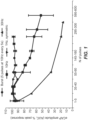
- Figure 1 illustrates how the responsiveness of the splenic nerve, unmyelinated fibers, varies as a percentage of the peak response with respect to the number of pulses applied.
- APCS rate of fatigue
- FIG. 1 illustrates how the responsiveness of the splenic nerve, unmyelinated fibers, varies as a percentage of the peak response with respect to the number of pulses applied.
- a stimulation frequency of 10Hz causes fatigue, APCS, in the nerve also, but at a less rapid rate.
- stimulating the nerve with a frequency of 1Hz and stimulating the nerve with 5 pulses at 10Hz every 5 seconds causes less fatigue, APCS.
- Stimulating the nerve with a frequency of 1Hz causes almost no conduction slowing and stimulating the nerve with 5 pulses at 10Hz every 5 seconds also effectively prevents conduction slowing However, it is undesirable for stimulation to be limited to these frequencies and stimulation patterns. Frequencies between 1Hz and 10Hz are desirable.
- Unmyelinated fibers show a reduction in conduction velocities when they are subjected to a stimulus preceded by a conditioning stimulus, depending on the delay between the two pulses (the frequence of the stimulation) and also the total number of pulses generated.
- this phenomenon manifests as reduction in CAP amplitude and increase in latency, reduction in conduction velocity.
- the system comprises a first stimulator 5 and a second stimulator 7 operatively coupled to a controller 9 that controls stimulations applied by the stimulators 5, 7.
- the stimulators 5, 7 are attached to a nerve interface 9, such as an electrode cuff.
- the nerve interface 9 comprises an aperture that has an internal diameter (id 1 ) which is sized to receive the nerve 3.
- the first stimulator 5 and the second stimulator 7 are separated by a first distance (d 1 ).
- the internal diameter (id 1 ) may be approximately equal to, or greater than, 5mm.
- the internal diameter (id 1 ) may be approximately equal to, or less than, 13mm.
- the internal diameter (id 1 ) may be approximately 7.5mm.
- the first stimulator 5 comprises a first electrode 11 and the second stimulator 7 comprises a second electrode 13.
- the controller 9 is configured to stimulate the electrodes 11, 13 in order to provide either anodic pulses during which the controller 9 applies a negative current to one of the electrodes or cathodic pulses during which the controller 9 applies a positive current to one of the electrodes.
- the controller 9 is arranged to activate the first stimulator 5 in order to provide a first electrical stimulation to the nerve 3 for a first stimulation period. This induces electrical activity in the nerve 3, which may be an action potential in the nerve 3. This electrical activity travels along the nerve between the first stimulator 5 and the second stimulator 7.
- the controller 9 is also arranged to activate the second stimulator 7 in order to provide a second stimulation to the nerve 3 for second stimulation period. This induces electrical activity in the nerve 3, which may be an action potential in the nerve. This electrical activity travels along the nerve between the second stimulator 7 and the first stimulator 75
- the controller 9 may be configured to operate the first electrode 11 as a cathode and the second electrode 12 as an anode during a first phase. Then, the controller 9 may be configured to operate the first electrode 11 as an anode and the second electrode 13 as a cathode during a second phase. The first and the second phase may be within the same stimulation period.
- the controller 9 is arranged to set a time interval that defines a delay between stimulating the first stimulator 5 and the second stimulator 7. This may be preprogramed and/or the controller 9 may be provided with a user interface that allows an operator to set the time interval.
- the first stimulator 5 comprises the first electrode 11 and a third electrode 12.
- the second stimulator 7 comprises the second electrode 13 and the third electrode 12.
- the first stimulator 11 and the second stimulator 7 share the third electrode 12.
- the third electrode has a larger surface area than the first and second electrodes.
- the third electrode may, for example, be the IPG case.
- the controller 9 is configured to stimulate the electrodes 11, 12, 13 in order to provide either anodic pulses during which the controller 9 applies a negative current to one of the electrodes, or cathodic pulses during which the controller 9 applies a positive current to one of the electrodes.
- the controller 9 is arranged to activate the first stimulator 5 in order to provide a first electrical stimulation to the nerve 3 for a first stimulation period. In one example, this involves stimulating the first electrode 11 and/or the third electrode 12 in order to provide either an anodic pulse or a cathodic pulse. For an anodic pulse, the controller 9 applies a negative current to either one of the first electrode 11 or the third electrode 12. For a cathodic pulse, the controller 9 applies a positive current to either one of the first electrode 11 or the third electrode 12.
- the controller 9 is also arranged to activate the second stimulator 7 in order to provide a second stimulation to the nerve 3 for a second stimulation period. In one example, this involves stimulating the second electrode 13 and the third electrode 12 in order to provide either an anodic pulse or a cathodic pulse. For an anodic pulse, the controller 9 applies a negative current to either one of the second electrode 13 or the third electrode 12. For a cathodic pulse, the controller 9 applies a positive current to either one of the second electrode 13 or the third electrode 12.
- the controller 9 may be configured to operate the first electrode 11 and/or the second electrode 13 as a cathode and the third electrode 12 as an anode during a first phase. Then, the controller 9 may be configured to operate the first electrode 11 and/or the second electrode 13 as an anode and the third electrode 12 as a cathode during a second phase. The first and the second phase may be within the same stimulation period.
- FIG 4 illustrates an example of a timing sequence for the stimulation provided by the system 1 described with reference to Figures 2 and 3 .
- the first stimulator 5 stimulates the nerve 3 with a first electrical stimulation 111 for a first stimulation time period (t 1 ).
- the second stimulator 7 stimulates the nerve 3 with a second stimulation 121 for a second stimulation time period (t 2 ).
- the first stimulator 5 stimulates the nerve 3 with a third electrical stimulation 112 for the first stimulation time period, and after that the second stimulator 7 stimulates the nerve 3 with a fourth stimulation 122 for the second stimulation time period. This process can be repeated so that the first and second stimulators 5, 7 are activated alternately.
- the stimulations 111, 121, 112, 122 are square wave pulses. However, this is only one example, and different stimulation patterns could you used, such as a burst of pulses and/or biphasic pulses.
- the time interval (t i ) is set in order to ensure that the electrical activity induced by the first stimulation has subsided in the vicinity of the second stimulator before the second stimulation is activated.
- the delay is set as a function of the distance between the stimulators 5, 7 (i.e. the first distance d 1 ) and the speed of propagation of an action potential in the nerve.
- the time interval (t i ) comprises at least one component (t c ) (i.e. a first time period) that is defined by a function of the first distance (d 1 ) and the speed of propagation.
- This function defines that the first time period is approximately equal to, or greater than, the first distance (d 1 ) divided by the speed of propagation of an action potential in the nerve (v).
- the speed of propagation is the speed at which electrical signals will travel between the stimulators 5, 7.
- the function may written as follows: t c ⁇ d i v
- the speed of propagation for autonomic nerves is 0.5 mm/ms.
- the stimulation time periods, t 1 and t 2 may each be equal to 1 ms.
- the function may define the first time period as set out in the following table, giving rise to the combined effective stimulation frequency rates shown in Table 1: Table 1 Propagation Speed (v) First Distance (d 1 ) First Time Period (t c ) Stimulation Time Period (t 1 , t 2 ) Combined Stimulation Frequency 0.5 mm/ms ⁇ 3 mm ⁇ 6 ms 1 ms ⁇ 142 Hz 0.5 mm/ms ⁇ 5 mm ⁇ 10 ms 1 ms ⁇ 90 Hz 0.5 mm/ms ⁇ 6 mm ⁇ 12 ms 1 ms ⁇ 76 0.5 mm/ms ⁇ 6.4 mm ⁇ 12.8 ms 1 ms ⁇ 72 Hz
- the time interval (t i ) comprises at least the first time period (t c ) defined by the function discussed above and a buffer time period (t b ).
- the time interval (t i ) is defined as being greater than, or equal to, the sum of the first time period (t c ) and the buffer time period (t b ).
- This function may written as follows: t i ⁇ d i v + t b
- the buffer time period (t b ) may be equal to, or greater than, 10ms. This provides a sufficient length of time for autonomic nerve fibres to recover. However, other time periods could be used depending on the type of nerve. For instance, different fiber types and diameters will have different refractory periods. Myelinated fibers have very short recovery times in the order of a couple milliseconds. Unmyelinated fibers, like C-fibers, need recovery times in the order of 10 ms. The recovery time within a fiber type will be shorter for larger diameters and longer for smaller diameters. Also, increasing the length of the buffer time period (t b ) increases the likelihood of the nerve fully recovering before the next stimulation is applied, but reduces the frequency.
- the buffer time period (t b ) can be adjusted in order to find the optimal trade-off between frequency and recovery.
- An operator can adjust the buffer time period (t b ) by interacting with a user interface at the controller 9.
- Table 2 shows the time interval (t i ) values and the resulting frequency rates when using the propagation speed (v) is 0.5 mm/ms and the stimulation time periods (t 1 , t 2 ) are each.
- Table 2 FirstDistance (d 1 ) First Time Period (t c ) Buffer Time Period (t b ) Total Time Interval (t i ) Combined Stimulation Frequency ⁇ 3 mm ⁇ 6 ms ⁇ 10 ms ⁇ 16 ms ⁇ 58 Hz ⁇ 5 mm ⁇ 10 ms ⁇ 10 ms ⁇ 20 ms ⁇ 47 Hz ⁇ 6 mm ⁇ 12 ms ⁇ 10 ms ⁇ 22 ms ⁇ 43 Hz ⁇ 6.4 mm ⁇ 12.8 ms ⁇ 10 ms ⁇ 22.8 ms ⁇ 42 Hz
- Figures 5 and 6 illustrate specific examples of the simulation patterns provided by the system 1.
- the system 1 alternates the waveform polarity at each stimulator 5, 7 in order to allow anodic activation and cathodic activation.
- anodic stimulation can activate nerve fibers very close to the contact surface, while cathodic stimulation can activate fibers that are deeper.
- Figure 5 illustrates the current provided by the distal contact (E d ), the proximal contact (E p ) and the case of a bipolar neural interface.
- the neural interface stimulates the nerve with a symmetrical biphasic waveform.
- the case always serves as an anode while proximal contact and the distal contact are always cathodes with two distinct timing channels running at the same rate 180° out of phase. Being 180 degrees out of phase means the sequencing interval is one half the interval of the timing channels to maximize the recovery time in the event that a fiber is activated by both contacts.
- an action potential with 0.5 m/s conduction velocity will take ⁇ 12 ms to propagate between the contacts.
- the available recovery time of the nerve is one half of the interval minus ⁇ 12 ms, or 38 ms for 10 pps stimulation (i.e. 50 ms sequencing interval). In other words, if it takes 12 ms for the action potential to propagate to the second contact, then the fiber at that second contact has 38 ms to recover after being activated by the passing action potential.
- the recovery time (refractory time) for a first stimulated unmyelinated fiber, for example a C-fiber, is under 10 ms. This suggests the burst rate could be up to 30 pps without fatigue, APCS, or exit block if the average pulse rate is ⁇ 1 pps.
- the charge recovery phase of each pulse is delayed by at least 0.1 ms to reduce the activation threshold by avoiding membrane polarization reversal at the activation site before sodium channel activation.
- the alternating monopolar stimulation illustrated in Figure 5 allows all of the stimulator output current to be concentrated on a subset of contacts using the larger surface area of the implantable pulse generator (IPG) case to reduce the required compliance voltage and reduce current density to avoid IPG pocket stimulation.
- IPG implantable pulse generator
- Figure 6 illustrates a stimulation pattern that requires four timing channels in order to sequence the proximal contact and the distal contact as anodes and cathodes. This allows fibers very close to the contact surface to be activated be the anodic pulse while deeper fibers are activated by the cathodic pulse.
- an alternating bipolar waveform can be used to achieve the same effect as an alternate to monopolar stimulation as shown in Figure 5 .
- Passive charge recovery is used in this example as a way to avoid any possible activation by the recharge phase. There is likely no recharge phase activation even with a symmetrical biphasic pulse since reversal of membrane polarization after a sub-threshold primary phase is generally non-excitatory.
- composition “comprising” encompasses “including” as well as “consisting” e.g. a composition “comprising” X may consist exclusively of X or may include something additional e.g. X + Y. Unless otherwise indicated each embodiment as described herein may be combined with another embodiment as described herein, provided the resulting embodiment falls within the scope of the appended claims.
- the methods described herein are not explicitly claimed but may be performed by software in machine readable form on a tangible storage medium e.g. in the form of a computer program comprising computer program code means adapted to perform all the steps of any of the methods described herein when the program is run on a computer and where the computer program may be embodied on a computer readable medium.
- tangible (or non-transitory) storage media include disks, thumb drives, memory cards etc and do not include propagated signals.
- the software can be suitable for execution on a parallel processor or a serial processor such that the method steps may be carried out in any suitable order, or simultaneously. This acknowledges that firmware and software can be valuable, separately tradable commodities.
- modules such as the controller, described herein may be implemented in hardware or in software. Furthermore, the modules may be implemented at various locations throughout the system.
- a remote computer may store an example of the process described as software.
- a local or terminal computer may access the remote computer and download a part or all of the software to run the program.
- the local computer may download pieces of the software as needed, or execute some software instructions at the local terminal and some at the remote computer (or computer network).
- a dedicated circuit such as a DSP, programmable logic array, or the like.
Landscapes
- Health & Medical Sciences (AREA)
- Neurology (AREA)
- Neurosurgery (AREA)
- Engineering & Computer Science (AREA)
- Biomedical Technology (AREA)
- Nuclear Medicine, Radiotherapy & Molecular Imaging (AREA)
- Radiology & Medical Imaging (AREA)
- Life Sciences & Earth Sciences (AREA)
- Animal Behavior & Ethology (AREA)
- General Health & Medical Sciences (AREA)
- Public Health (AREA)
- Veterinary Medicine (AREA)
- Orthopedic Medicine & Surgery (AREA)
- Cardiology (AREA)
- Heart & Thoracic Surgery (AREA)
- Electrotherapy Devices (AREA)
Applications Claiming Priority (2)
| Application Number | Priority Date | Filing Date | Title |
|---|---|---|---|
| US201862782825P | 2018-12-20 | 2018-12-20 | |
| PCT/IB2019/060771 WO2020128748A1 (en) | 2018-12-20 | 2019-12-13 | Nerve stimulation system |
Publications (2)
| Publication Number | Publication Date |
|---|---|
| EP3897818A1 EP3897818A1 (en) | 2021-10-27 |
| EP3897818B1 true EP3897818B1 (en) | 2025-02-12 |
Family
ID=69159810
Family Applications (1)
| Application Number | Title | Priority Date | Filing Date |
|---|---|---|---|
| EP19835739.4A Active EP3897818B1 (en) | 2018-12-20 | 2019-12-13 | Nerve stimulation system |
Country Status (6)
| Country | Link |
|---|---|
| US (2) | US12036413B2 (https=) |
| EP (1) | EP3897818B1 (https=) |
| JP (2) | JP7592016B2 (https=) |
| CN (1) | CN113710311B (https=) |
| ES (1) | ES3015583T3 (https=) |
| WO (1) | WO2020128748A1 (https=) |
Families Citing this family (4)
| Publication number | Priority date | Publication date | Assignee | Title |
|---|---|---|---|---|
| US8934992B2 (en) | 2011-09-01 | 2015-01-13 | Inspire Medical Systems, Inc. | Nerve cuff |
| WO2019032890A1 (en) | 2017-08-11 | 2019-02-14 | Inspire Medical Systems, Inc. | SLEEVE ELECTRODE |
| US12390646B2 (en) | 2020-12-02 | 2025-08-19 | Inspire Medical Systems, Inc. | Implantable medical devices |
| KR20240044782A (ko) * | 2022-09-29 | 2024-04-05 | 서울대학교산학협력단 | 뇌심부 자극 장치 및 이의 제어 방법 |
Family Cites Families (25)
| Publication number | Priority date | Publication date | Assignee | Title |
|---|---|---|---|---|
| US4019518A (en) * | 1975-08-11 | 1977-04-26 | Medtronic, Inc. | Electrical stimulation system |
| CA1287879C (en) * | 1986-11-04 | 1991-08-20 | Thomas H. Thomson | Optimized nerve fiber stimulation |
| CA1313539C (en) * | 1987-02-02 | 1993-02-09 | Thomas H. Thomson | Nerve fiber stimulation using plural equally active electrodes |
| AU2423997A (en) | 1996-04-04 | 1997-10-29 | Medtronic, Inc. | Techniques for adjusting the locus of excitation of electrically excitable tissue |
| US6600954B2 (en) * | 2001-01-25 | 2003-07-29 | Biocontrol Medical Bcm Ltd. | Method and apparatus for selective control of nerve fibers |
| US8571653B2 (en) * | 2001-08-31 | 2013-10-29 | Bio Control Medical (B.C.M.) Ltd. | Nerve stimulation techniques |
| US20140046407A1 (en) * | 2001-08-31 | 2014-02-13 | Bio Control Medical (B.C.M.) Ltd. | Nerve stimulation techniques |
| US7162303B2 (en) * | 2002-04-08 | 2007-01-09 | Ardian, Inc. | Renal nerve stimulation method and apparatus for treatment of patients |
| US7860570B2 (en) * | 2002-06-20 | 2010-12-28 | Boston Scientific Neuromodulation Corporation | Implantable microstimulators and methods for unidirectional propagation of action potentials |
| US20080161878A1 (en) * | 2003-10-15 | 2008-07-03 | Tehrani Amir J | Device and method to for independently stimulating hemidiaphragms |
| US7295881B2 (en) * | 2003-12-29 | 2007-11-13 | Biocontrol Medical Ltd. | Nerve-branch-specific action-potential activation, inhibition, and monitoring |
| US20050246003A1 (en) * | 2004-04-28 | 2005-11-03 | Advanced Neuromodulation Systems, Inc. | Stimulation lead having pairs of stimulating electrodes spaced at different distances for providing electrical stimulation to different nerve tissues |
| US7881782B2 (en) * | 2005-04-20 | 2011-02-01 | Cardiac Pacemakers, Inc. | Neural stimulation system to prevent simultaneous energy discharges |
| US9539425B2 (en) * | 2006-10-13 | 2017-01-10 | Intelect Medical, Inc. | Systems and methods for treating medical conditions by stimulation of medial thalamic region |
| AU2012203591A1 (en) * | 2006-10-13 | 2012-07-12 | Cyberonics, Inc. | Obstructive sleep apnea treatment devices, systems and methods |
| US8019430B2 (en) * | 2007-03-21 | 2011-09-13 | Cochlear Limited | Stimulating auditory nerve fibers to provide pitch representation |
| US20130030497A1 (en) * | 2011-07-27 | 2013-01-31 | Medtronic, Inc. | Nerve stimulator for reduced muscle fatigue |
| CN107029349A (zh) * | 2012-03-09 | 2017-08-11 | 安特罗麦迪克斯公司 | 用在医疗设备中的安全特征件 |
| US8588909B1 (en) * | 2012-06-12 | 2013-11-19 | Pacesetter, Inc. | Triggered mode pacing for cardiac resynchronization therapy |
| DE102014104414A1 (de) * | 2014-03-28 | 2015-10-01 | Roland Mäusl | Nervenstimulationsgerät |
| EP3326689B1 (en) * | 2014-11-03 | 2022-03-30 | Presidio Medical, Inc. | Neuromodulation device |
| US20160158551A1 (en) | 2014-12-05 | 2016-06-09 | Pacesstter, Inc. | System and method for dorsal root block during spinal cord stimulation |
| US11980465B2 (en) * | 2015-04-03 | 2024-05-14 | Medtronic Xomed, Inc. | System and method for omni-directional bipolar stimulation of nerve tissue of a patient via a bipolar stimulation probe |
| EP3389768B1 (en) * | 2015-12-18 | 2023-03-01 | Medtronic, Inc. | High duty cycle electrical stimulation therapy |
| CA3034123A1 (en) * | 2016-08-16 | 2018-02-22 | The Governing Council Of The University Of Toronto | Systems, methods, and kits for peripheral nerve stimulation |
-
2019
- 2019-12-13 WO PCT/IB2019/060771 patent/WO2020128748A1/en not_active Ceased
- 2019-12-13 US US17/415,599 patent/US12036413B2/en active Active
- 2019-12-13 JP JP2021534954A patent/JP7592016B2/ja active Active
- 2019-12-13 EP EP19835739.4A patent/EP3897818B1/en active Active
- 2019-12-13 CN CN201980092711.7A patent/CN113710311B/zh active Active
- 2019-12-13 ES ES19835739T patent/ES3015583T3/es active Active
-
2024
- 2024-06-13 US US18/742,863 patent/US20240350809A1/en active Pending
- 2024-07-04 JP JP2024107885A patent/JP2024156669A/ja active Pending
Also Published As
| Publication number | Publication date |
|---|---|
| CN113710311B (zh) | 2024-07-30 |
| CN113710311A (zh) | 2021-11-26 |
| WO2020128748A1 (en) | 2020-06-25 |
| JP2022514289A (ja) | 2022-02-10 |
| US12036413B2 (en) | 2024-07-16 |
| US20240350809A1 (en) | 2024-10-24 |
| JP7592016B2 (ja) | 2024-11-29 |
| EP3897818A1 (en) | 2021-10-27 |
| US20220080208A1 (en) | 2022-03-17 |
| ES3015583T3 (en) | 2025-05-06 |
| JP2024156669A (ja) | 2024-11-06 |
Similar Documents
| Publication | Publication Date | Title |
|---|---|---|
| US20240350809A1 (en) | Nerve stimulation system | |
| US9872990B2 (en) | Method and apparatus for application of a neural stimulus | |
| US9155892B2 (en) | Method and apparatus for application of a neural stimulus | |
| US8204603B2 (en) | Blocking exogenous action potentials by an implantable medical device | |
| US6850802B2 (en) | Selective brain stimulation using conditioning pulses | |
| US9370654B2 (en) | High frequency stimulation to block laryngeal stimulation during vagal nerve stimulation | |
| CN103702715B (zh) | 终止生物组织的高频心律失常电状态的装置和方法 | |
| US12220580B2 (en) | Variable amplitude signals for neurological therapy, and associated systems and methods | |
| US20240033522A1 (en) | Intra-Stimulus Recruitment Control | |
| WO2021142517A1 (en) | System and method for stimulating neurons | |
| HK1196319B (en) | Apparatus for and method of terminating a high frequency arrhythmic electric state of a biological tissue |
Legal Events
| Date | Code | Title | Description |
|---|---|---|---|
| STAA | Information on the status of an ep patent application or granted ep patent |
Free format text: STATUS: UNKNOWN |
|
| STAA | Information on the status of an ep patent application or granted ep patent |
Free format text: STATUS: THE INTERNATIONAL PUBLICATION HAS BEEN MADE |
|
| PUAI | Public reference made under article 153(3) epc to a published international application that has entered the european phase |
Free format text: ORIGINAL CODE: 0009012 |
|
| STAA | Information on the status of an ep patent application or granted ep patent |
Free format text: STATUS: REQUEST FOR EXAMINATION WAS MADE |
|
| 17P | Request for examination filed |
Effective date: 20210715 |
|
| AK | Designated contracting states |
Kind code of ref document: A1 Designated state(s): AL AT BE BG CH CY CZ DE DK EE ES FI FR GB GR HR HU IE IS IT LI LT LU LV MC MK MT NL NO PL PT RO RS SE SI SK SM TR |
|
| DAV | Request for validation of the european patent (deleted) | ||
| DAX | Request for extension of the european patent (deleted) | ||
| GRAP | Despatch of communication of intention to grant a patent |
Free format text: ORIGINAL CODE: EPIDOSNIGR1 |
|
| STAA | Information on the status of an ep patent application or granted ep patent |
Free format text: STATUS: GRANT OF PATENT IS INTENDED |
|
| INTG | Intention to grant announced |
Effective date: 20240312 |
|
| GRAJ | Information related to disapproval of communication of intention to grant by the applicant or resumption of examination proceedings by the epo deleted |
Free format text: ORIGINAL CODE: EPIDOSDIGR1 |
|
| STAA | Information on the status of an ep patent application or granted ep patent |
Free format text: STATUS: REQUEST FOR EXAMINATION WAS MADE |
|
| INTC | Intention to grant announced (deleted) | ||
| RAP3 | Party data changed (applicant data changed or rights of an application transferred) |
Owner name: GALVANI BIOELECTRONICS LIMITED |
|
| GRAP | Despatch of communication of intention to grant a patent |
Free format text: ORIGINAL CODE: EPIDOSNIGR1 |
|
| STAA | Information on the status of an ep patent application or granted ep patent |
Free format text: STATUS: GRANT OF PATENT IS INTENDED |
|
| INTG | Intention to grant announced |
Effective date: 20240905 |
|
| GRAS | Grant fee paid |
Free format text: ORIGINAL CODE: EPIDOSNIGR3 |
|
| GRAA | (expected) grant |
Free format text: ORIGINAL CODE: 0009210 |
|
| STAA | Information on the status of an ep patent application or granted ep patent |
Free format text: STATUS: THE PATENT HAS BEEN GRANTED |
|
| AK | Designated contracting states |
Kind code of ref document: B1 Designated state(s): AL AT BE BG CH CY CZ DE DK EE ES FI FR GB GR HR HU IE IS IT LI LT LU LV MC MK MT NL NO PL PT RO RS SE SI SK SM TR |
|
| REG | Reference to a national code |
Ref country code: GB Ref legal event code: FG4D |
|
| REG | Reference to a national code |
Ref country code: CH Ref legal event code: EP |
|
| REG | Reference to a national code |
Ref country code: DE Ref legal event code: R096 Ref document number: 602019065888 Country of ref document: DE |
|
| P01 | Opt-out of the competence of the unified patent court (upc) registered |
Free format text: CASE NUMBER: APP_3777/2025 Effective date: 20250123 |
|
| REG | Reference to a national code |
Ref country code: IE Ref legal event code: FG4D Ref country code: NL Ref legal event code: FP |
|
| REG | Reference to a national code |
Ref country code: ES Ref legal event code: FG2A Ref document number: 3015583 Country of ref document: ES Kind code of ref document: T3 Effective date: 20250506 |
|
| PG25 | Lapsed in a contracting state [announced via postgrant information from national office to epo] |
Ref country code: RS Free format text: LAPSE BECAUSE OF FAILURE TO SUBMIT A TRANSLATION OF THE DESCRIPTION OR TO PAY THE FEE WITHIN THE PRESCRIBED TIME-LIMIT Effective date: 20250512 |
|
| PG25 | Lapsed in a contracting state [announced via postgrant information from national office to epo] |
Ref country code: FI Free format text: LAPSE BECAUSE OF FAILURE TO SUBMIT A TRANSLATION OF THE DESCRIPTION OR TO PAY THE FEE WITHIN THE PRESCRIBED TIME-LIMIT Effective date: 20250212 |
|
| PG25 | Lapsed in a contracting state [announced via postgrant information from national office to epo] |
Ref country code: PL Free format text: LAPSE BECAUSE OF FAILURE TO SUBMIT A TRANSLATION OF THE DESCRIPTION OR TO PAY THE FEE WITHIN THE PRESCRIBED TIME-LIMIT Effective date: 20250212 |
|
| REG | Reference to a national code |
Ref country code: LT Ref legal event code: MG9D |
|
| PG25 | Lapsed in a contracting state [announced via postgrant information from national office to epo] |
Ref country code: IS Free format text: LAPSE BECAUSE OF FAILURE TO SUBMIT A TRANSLATION OF THE DESCRIPTION OR TO PAY THE FEE WITHIN THE PRESCRIBED TIME-LIMIT Effective date: 20250612 Ref country code: NO Free format text: LAPSE BECAUSE OF FAILURE TO SUBMIT A TRANSLATION OF THE DESCRIPTION OR TO PAY THE FEE WITHIN THE PRESCRIBED TIME-LIMIT Effective date: 20250512 |
|
| PG25 | Lapsed in a contracting state [announced via postgrant information from national office to epo] |
Ref country code: HR Free format text: LAPSE BECAUSE OF FAILURE TO SUBMIT A TRANSLATION OF THE DESCRIPTION OR TO PAY THE FEE WITHIN THE PRESCRIBED TIME-LIMIT Effective date: 20250212 |
|
| PG25 | Lapsed in a contracting state [announced via postgrant information from national office to epo] |
Ref country code: PT Free format text: LAPSE BECAUSE OF FAILURE TO SUBMIT A TRANSLATION OF THE DESCRIPTION OR TO PAY THE FEE WITHIN THE PRESCRIBED TIME-LIMIT Effective date: 20250612 Ref country code: LV Free format text: LAPSE BECAUSE OF FAILURE TO SUBMIT A TRANSLATION OF THE DESCRIPTION OR TO PAY THE FEE WITHIN THE PRESCRIBED TIME-LIMIT Effective date: 20250212 |
|
| PG25 | Lapsed in a contracting state [announced via postgrant information from national office to epo] |
Ref country code: BG Free format text: LAPSE BECAUSE OF FAILURE TO SUBMIT A TRANSLATION OF THE DESCRIPTION OR TO PAY THE FEE WITHIN THE PRESCRIBED TIME-LIMIT Effective date: 20250212 Ref country code: GR Free format text: LAPSE BECAUSE OF FAILURE TO SUBMIT A TRANSLATION OF THE DESCRIPTION OR TO PAY THE FEE WITHIN THE PRESCRIBED TIME-LIMIT Effective date: 20250513 |
|
| REG | Reference to a national code |
Ref country code: AT Ref legal event code: MK05 Ref document number: 1765524 Country of ref document: AT Kind code of ref document: T Effective date: 20250212 |
|
| PG25 | Lapsed in a contracting state [announced via postgrant information from national office to epo] |
Ref country code: SE Free format text: LAPSE BECAUSE OF FAILURE TO SUBMIT A TRANSLATION OF THE DESCRIPTION OR TO PAY THE FEE WITHIN THE PRESCRIBED TIME-LIMIT Effective date: 20250212 |
|
| PG25 | Lapsed in a contracting state [announced via postgrant information from national office to epo] |
Ref country code: SM Free format text: LAPSE BECAUSE OF FAILURE TO SUBMIT A TRANSLATION OF THE DESCRIPTION OR TO PAY THE FEE WITHIN THE PRESCRIBED TIME-LIMIT Effective date: 20250212 |
|
| PG25 | Lapsed in a contracting state [announced via postgrant information from national office to epo] |
Ref country code: DK Free format text: LAPSE BECAUSE OF FAILURE TO SUBMIT A TRANSLATION OF THE DESCRIPTION OR TO PAY THE FEE WITHIN THE PRESCRIBED TIME-LIMIT Effective date: 20250212 |
|
| PG25 | Lapsed in a contracting state [announced via postgrant information from national office to epo] |
Ref country code: AT Free format text: LAPSE BECAUSE OF FAILURE TO SUBMIT A TRANSLATION OF THE DESCRIPTION OR TO PAY THE FEE WITHIN THE PRESCRIBED TIME-LIMIT Effective date: 20250212 |
|
| PG25 | Lapsed in a contracting state [announced via postgrant information from national office to epo] |
Ref country code: EE Free format text: LAPSE BECAUSE OF FAILURE TO SUBMIT A TRANSLATION OF THE DESCRIPTION OR TO PAY THE FEE WITHIN THE PRESCRIBED TIME-LIMIT Effective date: 20250212 Ref country code: CZ Free format text: LAPSE BECAUSE OF FAILURE TO SUBMIT A TRANSLATION OF THE DESCRIPTION OR TO PAY THE FEE WITHIN THE PRESCRIBED TIME-LIMIT Effective date: 20250212 |
|
| PG25 | Lapsed in a contracting state [announced via postgrant information from national office to epo] |
Ref country code: RO Free format text: LAPSE BECAUSE OF FAILURE TO SUBMIT A TRANSLATION OF THE DESCRIPTION OR TO PAY THE FEE WITHIN THE PRESCRIBED TIME-LIMIT Effective date: 20250212 |
|
| PG25 | Lapsed in a contracting state [announced via postgrant information from national office to epo] |
Ref country code: SK Free format text: LAPSE BECAUSE OF FAILURE TO SUBMIT A TRANSLATION OF THE DESCRIPTION OR TO PAY THE FEE WITHIN THE PRESCRIBED TIME-LIMIT Effective date: 20250212 |
|
| REG | Reference to a national code |
Ref country code: DE Ref legal event code: R097 Ref document number: 602019065888 Country of ref document: DE |
|
| PGFP | Annual fee paid to national office [announced via postgrant information from national office to epo] |
Ref country code: NL Payment date: 20251119 Year of fee payment: 7 |
|
| PLBE | No opposition filed within time limit |
Free format text: ORIGINAL CODE: 0009261 |
|
| STAA | Information on the status of an ep patent application or granted ep patent |
Free format text: STATUS: NO OPPOSITION FILED WITHIN TIME LIMIT |
|
| PGFP | Annual fee paid to national office [announced via postgrant information from national office to epo] |
Ref country code: DE Payment date: 20251126 Year of fee payment: 7 |
|
| PGFP | Annual fee paid to national office [announced via postgrant information from national office to epo] |
Ref country code: GB Payment date: 20251119 Year of fee payment: 7 |
|
| PGFP | Annual fee paid to national office [announced via postgrant information from national office to epo] |
Ref country code: IT Payment date: 20251119 Year of fee payment: 7 |
|
| PGFP | Annual fee paid to national office [announced via postgrant information from national office to epo] |
Ref country code: FR Payment date: 20251120 Year of fee payment: 7 |
|
| 26N | No opposition filed |
Effective date: 20251113 |
|
| PGFP | Annual fee paid to national office [announced via postgrant information from national office to epo] |
Ref country code: ES Payment date: 20260102 Year of fee payment: 7 |