EP3897486B1 - Actuation mechanism with arcuate levers - Google Patents
Actuation mechanism with arcuate levers Download PDFInfo
- Publication number
- EP3897486B1 EP3897486B1 EP20703527.0A EP20703527A EP3897486B1 EP 3897486 B1 EP3897486 B1 EP 3897486B1 EP 20703527 A EP20703527 A EP 20703527A EP 3897486 B1 EP3897486 B1 EP 3897486B1
- Authority
- EP
- European Patent Office
- Prior art keywords
- shaft
- levers
- housing
- surgical instrument
- lever
- Prior art date
- Legal status (The legal status is an assumption and is not a legal conclusion. Google has not performed a legal analysis and makes no representation as to the accuracy of the status listed.)
- Active
Links
Images



Classifications
-
- A—HUMAN NECESSITIES
- A61—MEDICAL OR VETERINARY SCIENCE; HYGIENE
- A61F—FILTERS IMPLANTABLE INTO BLOOD VESSELS; PROSTHESES; DEVICES PROVIDING PATENCY TO, OR PREVENTING COLLAPSING OF, TUBULAR STRUCTURES OF THE BODY, e.g. STENTS; ORTHOPAEDIC, NURSING OR CONTRACEPTIVE DEVICES; FOMENTATION; TREATMENT OR PROTECTION OF EYES OR EARS; BANDAGES, DRESSINGS OR ABSORBENT PADS; FIRST-AID KITS
- A61F9/00—Methods or devices for treatment of the eyes; Devices for putting in contact-lenses; Devices to correct squinting; Apparatus to guide the blind; Protective devices for the eyes, carried on the body or in the hand
- A61F9/007—Methods or devices for eye surgery
- A61F9/00736—Instruments for removal of intra-ocular material or intra-ocular injection, e.g. cataract instruments
-
- A—HUMAN NECESSITIES
- A61—MEDICAL OR VETERINARY SCIENCE; HYGIENE
- A61B—DIAGNOSIS; SURGERY; IDENTIFICATION
- A61B17/00—Surgical instruments, devices or methods
- A61B17/28—Surgical forceps
- A61B17/29—Forceps for use in minimally invasive surgery
-
- A—HUMAN NECESSITIES
- A61—MEDICAL OR VETERINARY SCIENCE; HYGIENE
- A61B—DIAGNOSIS; SURGERY; IDENTIFICATION
- A61B17/00—Surgical instruments, devices or methods
- A61B17/32—Surgical cutting instruments
- A61B17/3201—Scissors
-
- A—HUMAN NECESSITIES
- A61—MEDICAL OR VETERINARY SCIENCE; HYGIENE
- A61B—DIAGNOSIS; SURGERY; IDENTIFICATION
- A61B17/00—Surgical instruments, devices or methods
- A61B2017/00831—Material properties
- A61B2017/00862—Material properties elastic or resilient
-
- A—HUMAN NECESSITIES
- A61—MEDICAL OR VETERINARY SCIENCE; HYGIENE
- A61B—DIAGNOSIS; SURGERY; IDENTIFICATION
- A61B17/00—Surgical instruments, devices or methods
- A61B2017/00831—Material properties
- A61B2017/00867—Material properties shape memory effect
-
- A—HUMAN NECESSITIES
- A61—MEDICAL OR VETERINARY SCIENCE; HYGIENE
- A61B—DIAGNOSIS; SURGERY; IDENTIFICATION
- A61B17/00—Surgical instruments, devices or methods
- A61B2017/00831—Material properties
- A61B2017/00955—Material properties thermoplastic
-
- A—HUMAN NECESSITIES
- A61—MEDICAL OR VETERINARY SCIENCE; HYGIENE
- A61B—DIAGNOSIS; SURGERY; IDENTIFICATION
- A61B17/00—Surgical instruments, devices or methods
- A61B17/28—Surgical forceps
- A61B17/29—Forceps for use in minimally invasive surgery
- A61B17/2909—Handles
- A61B2017/2912—Handles transmission of forces to actuating rod or piston
- A61B2017/2918—Handles transmission of forces to actuating rod or piston flexible handles
-
- A—HUMAN NECESSITIES
- A61—MEDICAL OR VETERINARY SCIENCE; HYGIENE
- A61B—DIAGNOSIS; SURGERY; IDENTIFICATION
- A61B17/00—Surgical instruments, devices or methods
- A61B17/28—Surgical forceps
- A61B17/29—Forceps for use in minimally invasive surgery
- A61B2017/2926—Details of heads or jaws
- A61B2017/2932—Transmission of forces to jaw members
-
- A—HUMAN NECESSITIES
- A61—MEDICAL OR VETERINARY SCIENCE; HYGIENE
- A61B—DIAGNOSIS; SURGERY; IDENTIFICATION
- A61B17/00—Surgical instruments, devices or methods
- A61B17/30—Surgical pincettes, i.e. surgical tweezers without pivotal connections
- A61B2017/305—Tweezer like handles with tubular extensions, inner slidable actuating members and distal tools, e.g. microsurgical instruments
-
- A—HUMAN NECESSITIES
- A61—MEDICAL OR VETERINARY SCIENCE; HYGIENE
- A61B—DIAGNOSIS; SURGERY; IDENTIFICATION
- A61B90/00—Instruments, implements or accessories specially adapted for surgery or diagnosis and not covered by any of the groups A61B1/00 - A61B50/00, e.g. for luxation treatment or for protecting wound edges
- A61B90/03—Automatic limiting or abutting means, e.g. for safety
- A61B2090/033—Abutting means, stops, e.g. abutting on tissue or skin
- A61B2090/034—Abutting means, stops, e.g. abutting on tissue or skin abutting on parts of the device itself
-
- A—HUMAN NECESSITIES
- A61—MEDICAL OR VETERINARY SCIENCE; HYGIENE
- A61F—FILTERS IMPLANTABLE INTO BLOOD VESSELS; PROSTHESES; DEVICES PROVIDING PATENCY TO, OR PREVENTING COLLAPSING OF, TUBULAR STRUCTURES OF THE BODY, e.g. STENTS; ORTHOPAEDIC, NURSING OR CONTRACEPTIVE DEVICES; FOMENTATION; TREATMENT OR PROTECTION OF EYES OR EARS; BANDAGES, DRESSINGS OR ABSORBENT PADS; FIRST-AID KITS
- A61F9/00—Methods or devices for treatment of the eyes; Devices for putting in contact-lenses; Devices to correct squinting; Apparatus to guide the blind; Protective devices for the eyes, carried on the body or in the hand
- A61F9/007—Methods or devices for eye surgery
Definitions
- the present disclosure relates generally to a surgical instrument having an actuation mechanism including resilient, arcuate levers.
- a surgeon is required to manipulate (e.g., remove, cut, peel, etc.) certain tissues within a body part by using forceps, scissors, etc.
- Examples of such surgical procedures are internal limiting membrane (ILM) removal and epiretinal membrane (ERM) removal for treating different macular surface diseases.
- ILM internal limiting membrane
- ELM epiretinal membrane
- Certain designs are currently used for providing a surgical instrument with an actuation mechanism that allows a surgeon to close and open the jaws of the forceps or scissors, which are located at the tip of a surgical instrument.
- the existing actuation mechanisms involve too many parts, are structurally complicated, and/or are difficult to assemble.
- US 5 549 627 A relates to a plurality of opposing flexible bows which are portions of a unitary injection bow member.
- US 2003/0171762 Al relates to an instrument dispenser having an actuation handle which can be squeezed.
- US 10 092 168 B1 is directed to a light transmitting medical instrument which comprises a light pipe having a first end operatively coupled to a light source and a second end having a functional tip having at least two arms.
- the present disclosure relates generally to a surgical instrument having an actuation mechanism including resilient, arcuate levers.
- an actuation mechanism including resilient, arcuate levers.
- a surgical instrument comprising a device comprising having a functional end configured to be inserted into a body part.
- the functional end may comprise forceps or scissors.
- the surgical instrument further comprises a shaft coupled to a proximal end of the device, and a shaft housing configured to receive a distal end of the shaft and operable to move along a central axis of the shaft.
- the surgical instrument further comprises a tube coupled to the distal end of the shaft housing and configured to partially house the device such that the functional end of the device at least partially extends beyond the distal end of the tube.
- the surgical instrument further comprises a plurality of arcuate levers, each arcuate lever having a proximal end coupled to the shaft and a distal end coupled to the shaft housing. Pressing one or more of the plurality of arcuate levers moves the shaft housing and tube toward the functional end the device, causing the tube to transition the device from a deactivated state to an activated state, such as closing the jaws of a pair of forceps if the functional end of device comprises forceps.
- Particular embodiments of the present disclosure provide a surgical instrument having an actuation mechanism including resilient, arcuate levers.
- FIG. 1 illustrates an example of a surgical instrument with a prior art actuation mechanism.
- surgical instrument 100 comprises a handle 102, a plurality of actuation levers 104, a housing 105, an actuation tube 106, and a device, shown as forceps 108, at the tip of the probe.
- Each actuation lever 104 is a single piece comprising a first leg 112 and a second leg 110 joined at flexible juncture 114. In other embodiments, the first leg 112 and second leg 110 may be separate pieces coupled together with a hinge.
- Each actuation lever 104 may be made from shape memory material, such as titanium, stainless steel or suitable thermoplastic.
- Actuation tube 106 may be any suitable medical grade tubing, such as titanium, stainless steel, or suitable polymer and is sized so that forceps 108 reciprocate easily within. Forceps 108 are generally made from stainless steel or titanium, but other materials may also be used.
- Surgical instrument 100 is designed so that in use, when the plurality of actuation levers 104 is in its relaxed state, forceps 108 protrude or extend beyond the distal end of actuation tube 106, which is coupled to a housing 105. Squeezing one or more of the actuation levers 104 causes the respective actuation lever 104 to flex at juncture 114, pushing housing 105 forward relative to handle 102. The forward movement of housing 105 is transferred to actuation tube 106, causing actuation tube 106 to slide forward over a distal portion of the jaws of forceps 108, thereby activating forceps 108 by compressing together the jaws. By closing jaws of forceps 108, the surgeon is able to, for example, grasp and peel a tissue (e.g., ILM) within a body part.
- a tissue e.g., ILM
- actuation levers 104 may be structurally complicated and/or difficult to assemble. Accordingly, certain embodiments described herein relate to an actuation handle with an actuation mechanism including arcuate levers. In particular embodiments, this may reduce the structural complexity of the actuation mechanism and allow for easier assembly.
- FIG. 2 illustrates an outside view of an example surgical instrument 200 in accordance with the teachings of the present disclosure.
- surgical instrument 200 comprises a rear cap 202, a shaft 204, a shaft housing 206, an actuation tube 208, a stop ring 214, a plurality of levers 210 (e.g., 210a, 210b, 210c, etc.), and a device 212.
- levers 210 e.g., 210a, 210b, 210c, etc.
- Device 212 may be any surgical device that is shaped to fit in tube 208 with a distal end that is referred to as a functional end (e.g., a movable or active end).
- a functional end e.g., a movable or active end
- device 212 may be shaped as a needle with a functional end, which may comprise forceps, scissors, etc., with jaws or arms.
- the proximal end (not shown) of device 212 is coupled to shaft 204, as shown in FIGs. 4 and 5 .
- Levers 210 are coupled to shaft housing 206 at their distal ends and to shaft 204 at their proximal ends. Each lever 210 has a generally arcuate shape such that the middle of each lever 210 is further away from shaft 204 and shaft housing 206 than the distal and proximal ends of the respective lever. Levers 210 are formed of resilient material (e.g., flexible and/or springy material) such that, when pressed inward toward shaft 204, levers 210 flex, but revert back to their at-rest positions when they are released. In certain embodiments, levers 210 are formed of polycarbonate, polyetheretherketone (PEEK), or similar thermoplastic material. Unlike the prior art levers 104 shown in FIG.
- PEEK polyetheretherketone
- levers 210 are not configured to flex at a discontinuity (e.g., junction 114 in FIG. 1 ). Instead, levers 210 are configured to flex similar to leaf springs. When a lever 210 is pressed inward towards shaft 204, the compression of the lever causes the lever 210 to transition from a first, steeper curvature to a second, shallower curvature, in the process moving the distal end of the lever 210 towards the distal end of instrument 200.
- Surgical instrument 200 is designed so that in use, when levers 210 are in their relaxed or at-rest state, the functional end of device 212 protrudes or extends beyond the distal end of tube 208. Note that FIG. 2 illustrates levers 210 in their at-rest or deactivated position while FIG. 5 illustrates levers 210 in their pressed or activated position.
- levers 210 When levers 210 are pressed, they push shaft housing 206 forward relative to shaft 204 and device 208. The forward movement of shaft housing 206 is transferred to tube 208, causing tube 208 to slide forward and activate device 212.
- Device 212 is activated as a result of the forward movement of tube 206, which presses the jaws or arms of device 212 together.
- An activated device refers to a device whose jaws or arms are closed.
- a stop ring 214 may be coupled to or placed around shaft housing 206 to limit the movement of levers 210 towards shaft housing 206. In other words, stop ring 214 prevents levers 210 from over extending (e.g., becoming completely flat) when, for example, a user applies too much pressure on them.
- Levers 210, shaft housing 206, stop ring 214, shaft 204, and tube 208 may be collectively referred to as an actuation handle that is configured to activate and deactivate device 212 of surgical instrument 100.
- surgical instrument 200 comprises seven levers 210. However, a fewer or larger number of levers 210 may be used in other embodiments.
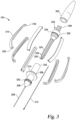
- FIG. 3 illustrates an exploded view of surgical instrument 200 of FIG. 2 .
- a proximal end 326 of shaft 204 is coupled to (e.g., press-fitted or inserted into) rear cap 202 while a distal end 328 of shaft 204 is inserted into the shaft housing 206.
- Shaft 204 also comprises a central element 330 that a distal end 332 of shaft housing 206 may, in certain embodiments, make contact with when levers 210 are relaxed (e.g., when device 212 is in the deactivated state). In such embodiments, when levers 210 are pressed, shaft housing 206 slides forward relative to shaft 204 such that distal end 332 of shaft 204 and central element 330 no longer touch. In other embodiments, distal end 332 of shaft housing 206 and central element 330 never touch even when levers 210 are relaxed.
- each lever 210 includes a lever tail 318 at its proximal end and a lever head 320 at its distal end.
- Each lever tail 318 is configured to couple the respective lever 210 to central element 330
- each lever head 320 is configured to couple the respective lever 210 to shaft housing 206.
- this coupling may be accomplished by having each lever tail and/or lever head mate with a corresponding housing on the central element 330 or shaft housing 206.
- central element 330 comprises a plurality of tail housings 324, each configured to house a lever tail 318 of a lever 210.
- each lever tail 318 may have a cylindrical shape and the corresponding tail housing 324 may comprise a u-shaped groove that is configured to house the cylindrical lever tail 318.
- a tail housing 324 and a lever tail 318 are coupled such that the lever tail 318 is able to rotate within and relative to the tail housing 324 when levers 210 are being pressed and released.
- shaft housing 206 comprises a plurality of head housings 322, each configured to house a lever head 320 of a lever 210. More specifically, each head housing 322 comprises a u-shaped groove that is configured to house a lever head 320 that, similar to a lever tail 318, is also shaped somewhat similar to a cylinder. Further, a head housing 322 and a lever head 320 are coupled such that the lever head 320 is able to rotate within and relative to the head housing 322 when levers 210 are being pressed and released. Note that the cylindrical shapes of lever tail 318 and lever head 320 as well as the shapes of tail housing 324 and head housing 322 are merely exemplary.
- levers 210 may be coupled to shaft 204 and shaft housing 206 using other mechanisms.
- lever tails 318 and shaft 204 may be coupled together using film hinges.
- film hinges may instead be used to couple lever heads 320 and shaft housing 206.
- shaft 204 further comprises a tube- or tunnel-shaped passage 325 into which the proximal end of device 212 is configured to be partially inserted.
- device 212 is attached or coupled to shaft 204 such as to prevent device 212 from moving, longitudinally or otherwise, relative to shaft 204.
- the proximal end of device 212 may be glued to the end of passage 325.
- shaft 204 comprises one or more protrusions 329 used for ensuring that shaft 204 does not rotate within and relative to shaft housing 206 when levers 210 are pressed.
- shaft 204 has four such protrusions 329 (three of which are visible in the figure) extending radially from the shaft at uniform intervals. Because of protrusions 329, when viewed down its central axis, shaft 204 may have a cross-shaped cross-section. As shown in FIG. 3 , shaft 204 comprises similar protrusions at its proximal end.
- protrusions 329 correspond to a plurality of receptacles (not illustrated) on the interior of shaft housing 206 into which protrusions 329 may be inserted.
- the interaction of protrusions 329 and these receptacles helps limit or prevent shaft 204 from rotating in relation to shaft housing 206 when levers 210 are pressed.
- shaft 204 has been described above as having four protrusions 329, in other embodiments shaft 204 may comprise other numbers and arrangements of protrusions.
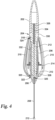
- FIG. 4 illustrates a cross-sectional view of surgical instrument 200 when levers 210 are in a relaxed or at-rest position, in accordance with a particular embodiment.
- proximal end 326 of shaft 204 is inserted into rear cap 204 while distal end 328 of shaft 204 is inserted into shaft housing 206.
- the proximal end of device 212 is coupled to a device housing 334 of shaft 204.
- Device housing 334 is a cylindrical element into which the proximal end of device 212 is partially inserted. In other examples, device housing 334 may be of any other suitable shape.
- the proximal end of device 212 and device housing 334 may be coupled together using adhesive material. In other embodiments, one of a plurality of other techniques may be used for coupling the proximal end of device 212 and device housing 334.
- device 212 extends through passage 325 of shaft 204 as well as tube 208.
- the distal or functional end of device 212 extends beyond the distal end of tube 208.
- device 212 is in a deactivated state.
- the arcuate length of levers 210 directly correspond to how far shaft housing 206 slides forward when levers 210 are pressed. The larger the arcuate length of levers 210 (e.g., the steeper the curve of levers 210), the further shaft housing 206 slides forward when levers 210 are pressed inward.
- FIG. 5 illustrates a cross-sectional view of surgical instrument 200 when device 212 is in the activated state, in accordance with a particular embodiment.
- levers 210 flex when they are pressed inward toward shaft 204, transitioning from a first, steeper curvature to a second, shallower curvature and, as a result, move or push shaft housing 206 forward relative to shaft 204 and device 208.
- the forward movement of shaft housing 206 is transferred to tube 208, causing tube 208 to slide forward and activate device 212.
- shaft housing 206 has moved forward such that distal end 332 of shaft housing 206 is separated from central element 330 of shaft 204 by a larger distance.
- the functional end of device 212 is activated because the jaws or arms are closed by the distal end of tube 208.
- levers 210 When levers 210 are released, they transition back to their original curvature, pulling shaft housing 206 backward, causing tube 208 to deactivate the functional end of device 212 by opening the jaws or arms.
- levers 210 are resilient, pressing them results a certain amount of spring force that causes levers 210 to revert back to their at-rest state when they are released.
Landscapes
- Health & Medical Sciences (AREA)
- Life Sciences & Earth Sciences (AREA)
- Surgery (AREA)
- Ophthalmology & Optometry (AREA)
- Public Health (AREA)
- Engineering & Computer Science (AREA)
- Biomedical Technology (AREA)
- Heart & Thoracic Surgery (AREA)
- Animal Behavior & Ethology (AREA)
- General Health & Medical Sciences (AREA)
- Nuclear Medicine, Radiotherapy & Molecular Imaging (AREA)
- Veterinary Medicine (AREA)
- Medical Informatics (AREA)
- Molecular Biology (AREA)
- Vascular Medicine (AREA)
- Surgical Instruments (AREA)
Applications Claiming Priority (2)
| Application Number | Priority Date | Filing Date | Title |
|---|---|---|---|
| US201962799785P | 2019-02-01 | 2019-02-01 | |
| PCT/IB2020/050572 WO2020157617A1 (en) | 2019-02-01 | 2020-01-24 | Actuation mechanism with arcuate levers |
Publications (2)
| Publication Number | Publication Date |
|---|---|
| EP3897486A1 EP3897486A1 (en) | 2021-10-27 |
| EP3897486B1 true EP3897486B1 (en) | 2025-02-05 |
Family
ID=69467594
Family Applications (1)
| Application Number | Title | Priority Date | Filing Date |
|---|---|---|---|
| EP20703527.0A Active EP3897486B1 (en) | 2019-02-01 | 2020-01-24 | Actuation mechanism with arcuate levers |
Country Status (4)
| Country | Link |
|---|---|
| US (1) | US11298146B2 (https=) |
| EP (1) | EP3897486B1 (https=) |
| JP (1) | JP7488823B2 (https=) |
| WO (1) | WO2020157617A1 (https=) |
Families Citing this family (7)
| Publication number | Priority date | Publication date | Assignee | Title |
|---|---|---|---|---|
| USD934424S1 (en) * | 2019-08-29 | 2021-10-26 | Alcon Inc. | 360 degree actuation handle |
| JP7655897B2 (ja) * | 2019-08-29 | 2025-04-02 | アルコン インコーポレイティド | 溝付き作動レバーを備えた作動機構 |
| US11752036B2 (en) | 2019-10-16 | 2023-09-12 | Alcon Inc. | Membrane delamination device |
| US12070418B2 (en) | 2019-10-16 | 2024-08-27 | Alcon Inc. | Membrane delamination device |
| US20220296415A1 (en) * | 2021-03-22 | 2022-09-22 | Tarek Hassan | Suction forceps |
| US20240000471A1 (en) * | 2022-06-30 | 2024-01-04 | Xrv-Ip, Llc | Forceps with deflectable grasping platforms |
| CN115844629B (zh) * | 2022-12-23 | 2024-10-18 | 爱尔眼科医院集团四川眼科医院有限公司 | 基于后驱动结构的眼用镊 |
Family Cites Families (33)
| Publication number | Priority date | Publication date | Assignee | Title |
|---|---|---|---|---|
| DE3526821A1 (de) | 1985-07-26 | 1987-02-05 | Ewald Hensler | Griffstueck mit betaetigungsvorrichtung fuer ein handbetaetigtes chirurgisches mikroinstrument |
| US5147378A (en) * | 1991-03-05 | 1992-09-15 | Harold Markham | Grapsing forceps |
| US5549627A (en) * | 1994-10-21 | 1996-08-27 | Kieturakis; Maciej J. | Surgical instruments and method for applying progressive intracorporeal traction |
| US5634918A (en) * | 1994-10-26 | 1997-06-03 | Grieshaber & Co. Ag Schaffhausen | Ophthalmic surgical instrument |
| US6488695B1 (en) | 2000-08-17 | 2002-12-03 | Alcon, Inc. | Ophthalmologic surgical probe |
| US20030171762A1 (en) * | 2000-08-17 | 2003-09-11 | Forchette Mark J. | Instrument dispenser |
| AU2001292584A1 (en) | 2000-10-12 | 2002-04-22 | Alcon Inc. | Microsurgical instrument |
| US6482198B2 (en) * | 2001-04-19 | 2002-11-19 | Duke University | Hand-held surgical instruments with omni-circumferential actuation capabilities |
| WO2003094589A2 (en) * | 2002-05-06 | 2003-11-20 | Duke University | Omni-actuable hand-held surgical instruments |
| CN101299972B (zh) | 2005-10-31 | 2012-02-01 | 爱尔康公司 | 延伸的小号照明器 |
| US8187293B2 (en) | 2006-02-06 | 2012-05-29 | Novartis Ag | Microsurgical instrument |
| US20070185514A1 (en) | 2006-02-06 | 2007-08-09 | Kirchhevel G L | Microsurgical instrument |
| WO2010064670A1 (ja) | 2008-12-05 | 2010-06-10 | Hoya株式会社 | 眼科用手術器具 |
| JP5179346B2 (ja) * | 2008-12-26 | 2013-04-10 | オリンパス株式会社 | 内視鏡装置 |
| US10092168B1 (en) * | 2009-08-17 | 2018-10-09 | Bionix Development Corporation | Lighted medical instrument |
| US8585735B2 (en) * | 2010-05-12 | 2013-11-19 | Ravi Nallakrishnan | Handle for surgical forceps and the like |
| US9428254B1 (en) | 2010-09-24 | 2016-08-30 | Katalyst Surgical, Llc | Microsurgical handle and instrument |
| CA2801744C (en) * | 2012-01-17 | 2015-10-13 | Covidien Lp | Material removal device and method of use |
| US9149389B2 (en) | 2012-08-31 | 2015-10-06 | Katalyst Surgical, Llc | Microsurgical handle and instrument |
| EP3228286A1 (en) | 2012-09-17 | 2017-10-11 | Novartis AG | Expanding ocular impant devices |
| US9226762B2 (en) | 2012-11-07 | 2016-01-05 | Katalyst Surgical, Llc | Atraumatic microsurgical forceps |
| US20140142603A1 (en) | 2012-11-19 | 2014-05-22 | Katalyst Surgical, Llc | Microsurgical instrument handle |
| US9827141B2 (en) * | 2013-06-21 | 2017-11-28 | Novartis Ag | Systems and techniques for tissue manipulation during ocular surgery |
| US20150173944A1 (en) | 2013-12-23 | 2015-06-25 | Novartis Ag | Systems and methods for attaching a surgical instrument tip |
| US9247951B1 (en) | 2015-08-20 | 2016-02-02 | Katalyst Surgical, Llc | Microsurgical handle and instrument |
| US20170079675A1 (en) | 2015-09-18 | 2017-03-23 | Katalyst Surgical, Llc | Tapered membrane removing forceps |
| US20170086871A1 (en) | 2015-09-24 | 2017-03-30 | Katalyst Surgical, Llc | Asymmetric membrane removing forceps |
| US20170100114A1 (en) | 2015-10-12 | 2017-04-13 | Katalyst Surgical, Llc | Instrument handle and replaceable tip |
| EP3471673A1 (en) | 2016-06-16 | 2019-04-24 | Katalyst Surgical, LLC | Reusable instrument handle with single- use tip |
| US20180014849A1 (en) | 2016-07-17 | 2018-01-18 | Katalyst Surgical, Llc | Single-use instrument tip for customized reusable handles |
| US10646375B2 (en) | 2017-01-12 | 2020-05-12 | Alcon Inc. | Systems and methods for pressure-driven tool actuation |
| US10695043B2 (en) | 2017-02-21 | 2020-06-30 | Katalyst Surgical, Llc | Surgical instrument subcomponent integration by additive manufacturing |
| US11246752B2 (en) | 2018-02-09 | 2022-02-15 | Alcon Inc. | Surgical tool attachment systems and method of use |
-
2020
- 2020-01-24 US US16/751,363 patent/US11298146B2/en active Active
- 2020-01-24 JP JP2021541231A patent/JP7488823B2/ja active Active
- 2020-01-24 EP EP20703527.0A patent/EP3897486B1/en active Active
- 2020-01-24 WO PCT/IB2020/050572 patent/WO2020157617A1/en not_active Ceased
Also Published As
| Publication number | Publication date |
|---|---|
| EP3897486A1 (en) | 2021-10-27 |
| JP2022519179A (ja) | 2022-03-22 |
| JP7488823B2 (ja) | 2024-05-22 |
| WO2020157617A1 (en) | 2020-08-06 |
| US11298146B2 (en) | 2022-04-12 |
| US20200246034A1 (en) | 2020-08-06 |
Similar Documents
| Publication | Publication Date | Title |
|---|---|---|
| EP3897486B1 (en) | Actuation mechanism with arcuate levers | |
| US12178461B2 (en) | Actuation mechanism with grooved actuation levers | |
| CN104994793B (zh) | 一次性撕囊镊子 | |
| CN106999301B (zh) | 具有可旋转的挠性轴的鼓膜穿刺管递送装置 | |
| JP3791421B2 (ja) | 眼内レンズの挿入器具 | |
| CN105050555B (zh) | 用于插入人工晶状体的系统和方法 | |
| US9827141B2 (en) | Systems and techniques for tissue manipulation during ocular surgery | |
| US5707377A (en) | Ligation clip remover | |
| US9750539B2 (en) | Medical instrument | |
| EP3860535B1 (en) | Actuation handle | |
| CN211535128U (zh) | 预装式囊袋张力环推注器 | |
| CN109009424A (zh) | 外科用电极组件 | |
| CN209032628U (zh) | 外科用电极组件 | |
| CN219184489U (zh) | 眼科手术镊 |
Legal Events
| Date | Code | Title | Description |
|---|---|---|---|
| STAA | Information on the status of an ep patent application or granted ep patent |
Free format text: STATUS: UNKNOWN |
|
| STAA | Information on the status of an ep patent application or granted ep patent |
Free format text: STATUS: THE INTERNATIONAL PUBLICATION HAS BEEN MADE |
|
| PUAI | Public reference made under article 153(3) epc to a published international application that has entered the european phase |
Free format text: ORIGINAL CODE: 0009012 |
|
| STAA | Information on the status of an ep patent application or granted ep patent |
Free format text: STATUS: REQUEST FOR EXAMINATION WAS MADE |
|
| 17P | Request for examination filed |
Effective date: 20210720 |
|
| AK | Designated contracting states |
Kind code of ref document: A1 Designated state(s): AL AT BE BG CH CY CZ DE DK EE ES FI FR GB GR HR HU IE IS IT LI LT LU LV MC MK MT NL NO PL PT RO RS SE SI SK SM TR |
|
| DAV | Request for validation of the european patent (deleted) | ||
| DAX | Request for extension of the european patent (deleted) | ||
| STAA | Information on the status of an ep patent application or granted ep patent |
Free format text: STATUS: EXAMINATION IS IN PROGRESS |
|
| 17Q | First examination report despatched |
Effective date: 20220809 |
|
| P01 | Opt-out of the competence of the unified patent court (upc) registered |
Effective date: 20230508 |
|
| GRAP | Despatch of communication of intention to grant a patent |
Free format text: ORIGINAL CODE: EPIDOSNIGR1 |
|
| STAA | Information on the status of an ep patent application or granted ep patent |
Free format text: STATUS: GRANT OF PATENT IS INTENDED |
|
| RIC1 | Information provided on ipc code assigned before grant |
Ipc: A61B 17/30 20060101ALN20240819BHEP Ipc: A61B 17/29 20060101ALI20240819BHEP Ipc: A61F 9/007 20060101AFI20240819BHEP |
|
| INTG | Intention to grant announced |
Effective date: 20240828 |
|
| GRAS | Grant fee paid |
Free format text: ORIGINAL CODE: EPIDOSNIGR3 |
|
| GRAA | (expected) grant |
Free format text: ORIGINAL CODE: 0009210 |
|
| STAA | Information on the status of an ep patent application or granted ep patent |
Free format text: STATUS: THE PATENT HAS BEEN GRANTED |
|
| AK | Designated contracting states |
Kind code of ref document: B1 Designated state(s): AL AT BE BG CH CY CZ DE DK EE ES FI FR GB GR HR HU IE IS IT LI LT LU LV MC MK MT NL NO PL PT RO RS SE SI SK SM TR |
|
| REG | Reference to a national code |
Ref country code: GB Ref legal event code: FG4D |
|
| REG | Reference to a national code |
Ref country code: CH Ref legal event code: EP |
|
| REG | Reference to a national code |
Ref country code: IE Ref legal event code: FG4D |
|
| REG | Reference to a national code |
Ref country code: DE Ref legal event code: R096 Ref document number: 602020045736 Country of ref document: DE |
|
| REG | Reference to a national code |
Ref country code: NL Ref legal event code: FP |
|
| PG25 | Lapsed in a contracting state [announced via postgrant information from national office to epo] |
Ref country code: RS Free format text: LAPSE BECAUSE OF FAILURE TO SUBMIT A TRANSLATION OF THE DESCRIPTION OR TO PAY THE FEE WITHIN THE PRESCRIBED TIME-LIMIT Effective date: 20250505 |
|
| PG25 | Lapsed in a contracting state [announced via postgrant information from national office to epo] |
Ref country code: FI Free format text: LAPSE BECAUSE OF FAILURE TO SUBMIT A TRANSLATION OF THE DESCRIPTION OR TO PAY THE FEE WITHIN THE PRESCRIBED TIME-LIMIT Effective date: 20250205 |
|
| PG25 | Lapsed in a contracting state [announced via postgrant information from national office to epo] |
Ref country code: PL Free format text: LAPSE BECAUSE OF FAILURE TO SUBMIT A TRANSLATION OF THE DESCRIPTION OR TO PAY THE FEE WITHIN THE PRESCRIBED TIME-LIMIT Effective date: 20250205 |
|
| PG25 | Lapsed in a contracting state [announced via postgrant information from national office to epo] |
Ref country code: ES Free format text: LAPSE BECAUSE OF FAILURE TO SUBMIT A TRANSLATION OF THE DESCRIPTION OR TO PAY THE FEE WITHIN THE PRESCRIBED TIME-LIMIT Effective date: 20250205 |
|
| REG | Reference to a national code |
Ref country code: LT Ref legal event code: MG9D |
|
| PG25 | Lapsed in a contracting state [announced via postgrant information from national office to epo] |
Ref country code: IS Free format text: LAPSE BECAUSE OF FAILURE TO SUBMIT A TRANSLATION OF THE DESCRIPTION OR TO PAY THE FEE WITHIN THE PRESCRIBED TIME-LIMIT Effective date: 20250605 Ref country code: NO Free format text: LAPSE BECAUSE OF FAILURE TO SUBMIT A TRANSLATION OF THE DESCRIPTION OR TO PAY THE FEE WITHIN THE PRESCRIBED TIME-LIMIT Effective date: 20250505 |
|
| PG25 | Lapsed in a contracting state [announced via postgrant information from national office to epo] |
Ref country code: HR Free format text: LAPSE BECAUSE OF FAILURE TO SUBMIT A TRANSLATION OF THE DESCRIPTION OR TO PAY THE FEE WITHIN THE PRESCRIBED TIME-LIMIT Effective date: 20250205 |
|
| PG25 | Lapsed in a contracting state [announced via postgrant information from national office to epo] |
Ref country code: PT Free format text: LAPSE BECAUSE OF FAILURE TO SUBMIT A TRANSLATION OF THE DESCRIPTION OR TO PAY THE FEE WITHIN THE PRESCRIBED TIME-LIMIT Effective date: 20250605 Ref country code: LV Free format text: LAPSE BECAUSE OF FAILURE TO SUBMIT A TRANSLATION OF THE DESCRIPTION OR TO PAY THE FEE WITHIN THE PRESCRIBED TIME-LIMIT Effective date: 20250205 |
|
| PG25 | Lapsed in a contracting state [announced via postgrant information from national office to epo] |
Ref country code: BG Free format text: LAPSE BECAUSE OF FAILURE TO SUBMIT A TRANSLATION OF THE DESCRIPTION OR TO PAY THE FEE WITHIN THE PRESCRIBED TIME-LIMIT Effective date: 20250205 Ref country code: GR Free format text: LAPSE BECAUSE OF FAILURE TO SUBMIT A TRANSLATION OF THE DESCRIPTION OR TO PAY THE FEE WITHIN THE PRESCRIBED TIME-LIMIT Effective date: 20250506 |
|
| REG | Reference to a national code |
Ref country code: AT Ref legal event code: MK05 Ref document number: 1764756 Country of ref document: AT Kind code of ref document: T Effective date: 20250205 |
|
| PG25 | Lapsed in a contracting state [announced via postgrant information from national office to epo] |
Ref country code: SE Free format text: LAPSE BECAUSE OF FAILURE TO SUBMIT A TRANSLATION OF THE DESCRIPTION OR TO PAY THE FEE WITHIN THE PRESCRIBED TIME-LIMIT Effective date: 20250205 |
|
| PG25 | Lapsed in a contracting state [announced via postgrant information from national office to epo] |
Ref country code: SM Free format text: LAPSE BECAUSE OF FAILURE TO SUBMIT A TRANSLATION OF THE DESCRIPTION OR TO PAY THE FEE WITHIN THE PRESCRIBED TIME-LIMIT Effective date: 20250205 |
|
| PG25 | Lapsed in a contracting state [announced via postgrant information from national office to epo] |
Ref country code: DK Free format text: LAPSE BECAUSE OF FAILURE TO SUBMIT A TRANSLATION OF THE DESCRIPTION OR TO PAY THE FEE WITHIN THE PRESCRIBED TIME-LIMIT Effective date: 20250205 |
|
| PG25 | Lapsed in a contracting state [announced via postgrant information from national office to epo] |
Ref country code: AT Free format text: LAPSE BECAUSE OF FAILURE TO SUBMIT A TRANSLATION OF THE DESCRIPTION OR TO PAY THE FEE WITHIN THE PRESCRIBED TIME-LIMIT Effective date: 20250205 |
|
| PG25 | Lapsed in a contracting state [announced via postgrant information from national office to epo] |
Ref country code: CZ Free format text: LAPSE BECAUSE OF FAILURE TO SUBMIT A TRANSLATION OF THE DESCRIPTION OR TO PAY THE FEE WITHIN THE PRESCRIBED TIME-LIMIT Effective date: 20250205 Ref country code: EE Free format text: LAPSE BECAUSE OF FAILURE TO SUBMIT A TRANSLATION OF THE DESCRIPTION OR TO PAY THE FEE WITHIN THE PRESCRIBED TIME-LIMIT Effective date: 20250205 |
|
| PG25 | Lapsed in a contracting state [announced via postgrant information from national office to epo] |
Ref country code: RO Free format text: LAPSE BECAUSE OF FAILURE TO SUBMIT A TRANSLATION OF THE DESCRIPTION OR TO PAY THE FEE WITHIN THE PRESCRIBED TIME-LIMIT Effective date: 20250205 |
|
| PG25 | Lapsed in a contracting state [announced via postgrant information from national office to epo] |
Ref country code: SK Free format text: LAPSE BECAUSE OF FAILURE TO SUBMIT A TRANSLATION OF THE DESCRIPTION OR TO PAY THE FEE WITHIN THE PRESCRIBED TIME-LIMIT Effective date: 20250205 |
|
| REG | Reference to a national code |
Ref country code: DE Ref legal event code: R097 Ref document number: 602020045736 Country of ref document: DE |
|
| PLBE | No opposition filed within time limit |
Free format text: ORIGINAL CODE: 0009261 |
|
| STAA | Information on the status of an ep patent application or granted ep patent |
Free format text: STATUS: NO OPPOSITION FILED WITHIN TIME LIMIT |
|
| 26N | No opposition filed |
Effective date: 20251106 |
|
| PGFP | Annual fee paid to national office [announced via postgrant information from national office to epo] |
Ref country code: NL Payment date: 20251225 Year of fee payment: 7 |
|
| PGFP | Annual fee paid to national office [announced via postgrant information from national office to epo] |
Ref country code: DE Payment date: 20251216 Year of fee payment: 7 |
|
| PGFP | Annual fee paid to national office [announced via postgrant information from national office to epo] |
Ref country code: IT Payment date: 20251230 Year of fee payment: 7 |