EP3897466B1 - Energy conservation of a motor-driven digit - Google Patents
Energy conservation of a motor-driven digit Download PDFInfo
- Publication number
- EP3897466B1 EP3897466B1 EP19839140.1A EP19839140A EP3897466B1 EP 3897466 B1 EP3897466 B1 EP 3897466B1 EP 19839140 A EP19839140 A EP 19839140A EP 3897466 B1 EP3897466 B1 EP 3897466B1
- Authority
- EP
- European Patent Office
- Prior art keywords
- motor
- duty cycle
- controller
- finger digit
- threshold
- Prior art date
- Legal status (The legal status is an assumption and is not a legal conclusion. Google has not performed a legal analysis and makes no representation as to the accuracy of the status listed.)
- Active
Links
Images






Classifications
-
- A—HUMAN NECESSITIES
- A61—MEDICAL OR VETERINARY SCIENCE; HYGIENE
- A61F—FILTERS IMPLANTABLE INTO BLOOD VESSELS; PROSTHESES; DEVICES PROVIDING PATENCY TO, OR PREVENTING COLLAPSING OF, TUBULAR STRUCTURES OF THE BODY, e.g. STENTS; ORTHOPAEDIC, NURSING OR CONTRACEPTIVE DEVICES; FOMENTATION; TREATMENT OR PROTECTION OF EYES OR EARS; BANDAGES, DRESSINGS OR ABSORBENT PADS; FIRST-AID KITS
- A61F2/00—Filters implantable into blood vessels; Prostheses, i.e. artificial substitutes or replacements for parts of the body; Appliances for connecting them with the body; Devices providing patency to, or preventing collapsing of, tubular structures of the body, e.g. stents
- A61F2/50—Prostheses not implantable in the body
- A61F2/54—Artificial arms or hands or parts thereof
- A61F2/58—Elbows; Wrists ; Other joints; Hands
- A61F2/583—Hands; Wrist joints
- A61F2/586—Fingers
-
- A—HUMAN NECESSITIES
- A61—MEDICAL OR VETERINARY SCIENCE; HYGIENE
- A61F—FILTERS IMPLANTABLE INTO BLOOD VESSELS; PROSTHESES; DEVICES PROVIDING PATENCY TO, OR PREVENTING COLLAPSING OF, TUBULAR STRUCTURES OF THE BODY, e.g. STENTS; ORTHOPAEDIC, NURSING OR CONTRACEPTIVE DEVICES; FOMENTATION; TREATMENT OR PROTECTION OF EYES OR EARS; BANDAGES, DRESSINGS OR ABSORBENT PADS; FIRST-AID KITS
- A61F2/00—Filters implantable into blood vessels; Prostheses, i.e. artificial substitutes or replacements for parts of the body; Appliances for connecting them with the body; Devices providing patency to, or preventing collapsing of, tubular structures of the body, e.g. stents
- A61F2/50—Prostheses not implantable in the body
- A61F2/68—Operating or control means
- A61F2/70—Operating or control means electrical
-
- A—HUMAN NECESSITIES
- A61—MEDICAL OR VETERINARY SCIENCE; HYGIENE
- A61F—FILTERS IMPLANTABLE INTO BLOOD VESSELS; PROSTHESES; DEVICES PROVIDING PATENCY TO, OR PREVENTING COLLAPSING OF, TUBULAR STRUCTURES OF THE BODY, e.g. STENTS; ORTHOPAEDIC, NURSING OR CONTRACEPTIVE DEVICES; FOMENTATION; TREATMENT OR PROTECTION OF EYES OR EARS; BANDAGES, DRESSINGS OR ABSORBENT PADS; FIRST-AID KITS
- A61F2/00—Filters implantable into blood vessels; Prostheses, i.e. artificial substitutes or replacements for parts of the body; Appliances for connecting them with the body; Devices providing patency to, or preventing collapsing of, tubular structures of the body, e.g. stents
- A61F2/50—Prostheses not implantable in the body
- A61F2/68—Operating or control means
- A61F2/70—Operating or control means electrical
- A61F2/72—Bioelectric control, e.g. myoelectric
-
- B—PERFORMING OPERATIONS; TRANSPORTING
- B25—HAND TOOLS; PORTABLE POWER-DRIVEN TOOLS; MANIPULATORS
- B25J—MANIPULATORS; CHAMBERS PROVIDED WITH MANIPULATION DEVICES
- B25J9/00—Program-controlled manipulators
- B25J9/10—Program-controlled manipulators characterised by positioning means for manipulator elements
- B25J9/102—Gears specially adapted therefor, e.g. reduction gears
-
- B—PERFORMING OPERATIONS; TRANSPORTING
- B25—HAND TOOLS; PORTABLE POWER-DRIVEN TOOLS; MANIPULATORS
- B25J—MANIPULATORS; CHAMBERS PROVIDED WITH MANIPULATION DEVICES
- B25J9/00—Program-controlled manipulators
- B25J9/10—Program-controlled manipulators characterised by positioning means for manipulator elements
- B25J9/12—Program-controlled manipulators characterised by positioning means for manipulator elements electric
- B25J9/126—Rotary actuators
-
- B—PERFORMING OPERATIONS; TRANSPORTING
- B25—HAND TOOLS; PORTABLE POWER-DRIVEN TOOLS; MANIPULATORS
- B25J—MANIPULATORS; CHAMBERS PROVIDED WITH MANIPULATION DEVICES
- B25J9/00—Program-controlled manipulators
- B25J9/16—Program controls
- B25J9/1612—Program controls characterised by the hand, wrist, grip control
-
- H—ELECTRICITY
- H02—GENERATION; CONVERSION OR DISTRIBUTION OF ELECTRIC POWER
- H02P—CONTROL OR REGULATION OF ELECTRIC MOTORS, ELECTRIC GENERATORS OR DYNAMO-ELECTRIC CONVERTERS; CONTROLLING TRANSFORMERS, REACTORS OR CHOKE COILS
- H02P29/00—Arrangements for regulating or controlling electric motors, appropriate for both AC and DC motors
-
- H—ELECTRICITY
- H03—ELECTRONIC CIRCUITRY
- H03K—PULSE TECHNIQUE
- H03K5/00—Manipulating of pulses not covered by one of the other main groups of this subclass
- H03K5/156—Arrangements in which a continuous pulse train is transformed into a train having a desired pattern
- H03K5/1565—Arrangements in which a continuous pulse train is transformed into a train having a desired pattern the output pulses having a constant duty cycle
-
- A—HUMAN NECESSITIES
- A61—MEDICAL OR VETERINARY SCIENCE; HYGIENE
- A61F—FILTERS IMPLANTABLE INTO BLOOD VESSELS; PROSTHESES; DEVICES PROVIDING PATENCY TO, OR PREVENTING COLLAPSING OF, TUBULAR STRUCTURES OF THE BODY, e.g. STENTS; ORTHOPAEDIC, NURSING OR CONTRACEPTIVE DEVICES; FOMENTATION; TREATMENT OR PROTECTION OF EYES OR EARS; BANDAGES, DRESSINGS OR ABSORBENT PADS; FIRST-AID KITS
- A61F2/00—Filters implantable into blood vessels; Prostheses, i.e. artificial substitutes or replacements for parts of the body; Appliances for connecting them with the body; Devices providing patency to, or preventing collapsing of, tubular structures of the body, e.g. stents
- A61F2/50—Prostheses not implantable in the body
- A61F2/68—Operating or control means
- A61F2002/6836—Gears specially adapted therefor, e.g. reduction gears
-
- A—HUMAN NECESSITIES
- A61—MEDICAL OR VETERINARY SCIENCE; HYGIENE
- A61F—FILTERS IMPLANTABLE INTO BLOOD VESSELS; PROSTHESES; DEVICES PROVIDING PATENCY TO, OR PREVENTING COLLAPSING OF, TUBULAR STRUCTURES OF THE BODY, e.g. STENTS; ORTHOPAEDIC, NURSING OR CONTRACEPTIVE DEVICES; FOMENTATION; TREATMENT OR PROTECTION OF EYES OR EARS; BANDAGES, DRESSINGS OR ABSORBENT PADS; FIRST-AID KITS
- A61F2/00—Filters implantable into blood vessels; Prostheses, i.e. artificial substitutes or replacements for parts of the body; Appliances for connecting them with the body; Devices providing patency to, or preventing collapsing of, tubular structures of the body, e.g. stents
- A61F2/50—Prostheses not implantable in the body
- A61F2/68—Operating or control means
- A61F2/70—Operating or control means electrical
- A61F2002/701—Operating or control means electrical operated by electrically controlled means, e.g. solenoids or torque motors
-
- A—HUMAN NECESSITIES
- A61—MEDICAL OR VETERINARY SCIENCE; HYGIENE
- A61F—FILTERS IMPLANTABLE INTO BLOOD VESSELS; PROSTHESES; DEVICES PROVIDING PATENCY TO, OR PREVENTING COLLAPSING OF, TUBULAR STRUCTURES OF THE BODY, e.g. STENTS; ORTHOPAEDIC, NURSING OR CONTRACEPTIVE DEVICES; FOMENTATION; TREATMENT OR PROTECTION OF EYES OR EARS; BANDAGES, DRESSINGS OR ABSORBENT PADS; FIRST-AID KITS
- A61F2/00—Filters implantable into blood vessels; Prostheses, i.e. artificial substitutes or replacements for parts of the body; Appliances for connecting them with the body; Devices providing patency to, or preventing collapsing of, tubular structures of the body, e.g. stents
- A61F2/50—Prostheses not implantable in the body
- A61F2/68—Operating or control means
- A61F2/70—Operating or control means electrical
- A61F2002/704—Operating or control means electrical computer-controlled, e.g. robotic control
-
- A—HUMAN NECESSITIES
- A61—MEDICAL OR VETERINARY SCIENCE; HYGIENE
- A61F—FILTERS IMPLANTABLE INTO BLOOD VESSELS; PROSTHESES; DEVICES PROVIDING PATENCY TO, OR PREVENTING COLLAPSING OF, TUBULAR STRUCTURES OF THE BODY, e.g. STENTS; ORTHOPAEDIC, NURSING OR CONTRACEPTIVE DEVICES; FOMENTATION; TREATMENT OR PROTECTION OF EYES OR EARS; BANDAGES, DRESSINGS OR ABSORBENT PADS; FIRST-AID KITS
- A61F2/00—Filters implantable into blood vessels; Prostheses, i.e. artificial substitutes or replacements for parts of the body; Appliances for connecting them with the body; Devices providing patency to, or preventing collapsing of, tubular structures of the body, e.g. stents
- A61F2/50—Prostheses not implantable in the body
- A61F2/76—Means for assembling, fitting or testing prostheses, e.g. for measuring or balancing
- A61F2002/7615—Measuring means
- A61F2002/762—Measuring means for measuring dimensions, e.g. a distance
-
- A—HUMAN NECESSITIES
- A61—MEDICAL OR VETERINARY SCIENCE; HYGIENE
- A61F—FILTERS IMPLANTABLE INTO BLOOD VESSELS; PROSTHESES; DEVICES PROVIDING PATENCY TO, OR PREVENTING COLLAPSING OF, TUBULAR STRUCTURES OF THE BODY, e.g. STENTS; ORTHOPAEDIC, NURSING OR CONTRACEPTIVE DEVICES; FOMENTATION; TREATMENT OR PROTECTION OF EYES OR EARS; BANDAGES, DRESSINGS OR ABSORBENT PADS; FIRST-AID KITS
- A61F2/00—Filters implantable into blood vessels; Prostheses, i.e. artificial substitutes or replacements for parts of the body; Appliances for connecting them with the body; Devices providing patency to, or preventing collapsing of, tubular structures of the body, e.g. stents
- A61F2/50—Prostheses not implantable in the body
- A61F2/76—Means for assembling, fitting or testing prostheses, e.g. for measuring or balancing
- A61F2002/7615—Measuring means
- A61F2002/7625—Measuring means for measuring angular position
-
- A—HUMAN NECESSITIES
- A61—MEDICAL OR VETERINARY SCIENCE; HYGIENE
- A61F—FILTERS IMPLANTABLE INTO BLOOD VESSELS; PROSTHESES; DEVICES PROVIDING PATENCY TO, OR PREVENTING COLLAPSING OF, TUBULAR STRUCTURES OF THE BODY, e.g. STENTS; ORTHOPAEDIC, NURSING OR CONTRACEPTIVE DEVICES; FOMENTATION; TREATMENT OR PROTECTION OF EYES OR EARS; BANDAGES, DRESSINGS OR ABSORBENT PADS; FIRST-AID KITS
- A61F2/00—Filters implantable into blood vessels; Prostheses, i.e. artificial substitutes or replacements for parts of the body; Appliances for connecting them with the body; Devices providing patency to, or preventing collapsing of, tubular structures of the body, e.g. stents
- A61F2/50—Prostheses not implantable in the body
- A61F2/76—Means for assembling, fitting or testing prostheses, e.g. for measuring or balancing
- A61F2002/7615—Measuring means
- A61F2002/763—Measuring means for measuring spatial position, e.g. global positioning system [GPS]
-
- A—HUMAN NECESSITIES
- A61—MEDICAL OR VETERINARY SCIENCE; HYGIENE
- A61F—FILTERS IMPLANTABLE INTO BLOOD VESSELS; PROSTHESES; DEVICES PROVIDING PATENCY TO, OR PREVENTING COLLAPSING OF, TUBULAR STRUCTURES OF THE BODY, e.g. STENTS; ORTHOPAEDIC, NURSING OR CONTRACEPTIVE DEVICES; FOMENTATION; TREATMENT OR PROTECTION OF EYES OR EARS; BANDAGES, DRESSINGS OR ABSORBENT PADS; FIRST-AID KITS
- A61F2/00—Filters implantable into blood vessels; Prostheses, i.e. artificial substitutes or replacements for parts of the body; Appliances for connecting them with the body; Devices providing patency to, or preventing collapsing of, tubular structures of the body, e.g. stents
- A61F2/50—Prostheses not implantable in the body
- A61F2/76—Means for assembling, fitting or testing prostheses, e.g. for measuring or balancing
- A61F2002/7615—Measuring means
- A61F2002/7645—Measuring means for measuring torque, e.g. hinge or turning moment, moment of force
Definitions
- the present disclosure relates to prosthetics. More specifically, this disclosure relates to systems, methods, and apparatuses for reducing electrical noise and/or reducing energy consumption in a motor-driven digit of a prosthesis.
- electric motors have been incorporated into some prostheses to facilitate movements of one or more of the digits, such as prosthetic thumbs or fingers.
- an electric motor can introduce undesirable electrical noise into an associated prosthesis.
- an electric motor can consume a significant amount of energy. Improvements in this area are therefore desirable.
- US 2012/221122 which prior art closest to the present invention discloses a method of controlling a movable component of a prosthesis or orthosis.
- the method comprises moving the component by means of a motor and determining when movement of the component is arrested when the component bears against a surface. Thereafter a plurality of driving electrical pulses are applied to the motor in dependence on the determination and when movement of the component is arrested to thereby drive the motor so as to cause the component to bear against the surface with greater force.
- a prosthesis can implement an acceleration profile, which can reduce an energy consumption of a motor, or an amount of electrical and/or mechanical noise produced by a motor, as the motor as the motor transitions from an idle state to a non-idle state.
- a prosthesis can implement a deceleration profile, which can reduce the energy consumption of the motor, or an amount of electrical and/or mechanical noise produced by a motor, as the motor transitions from a non-idle state to an idle state.
- Amputees prefer prosthetic hands that have a long battery life and that mimic, as close as possible, the natural movement of a sound hand, including the speed at which a sound hand can react or move into a particular hand grip.
- the battery life of a prosthetic hand is inversely related to the speeds of the motors of the prosthetic hand. Accordingly, it can be difficult to navigate the compromise between a speed of the prosthetic hand and its power consumption.
- Routines and methods disclosed herein can increase a power efficiency of a prosthetic hand without significantly reducing the speed at which it operates.
- routines and methods disclosed herein can implement an acceleration profile, which can reduce the energy consumption of a motor as the motor transitions from an idle state to a non-idle state.
- routines and methods disclosed herein can implement a deceleration profile, which can reduce the energy consumption of a motor as the motor transitions from a non-idle state to an idle state.
- routines and methods disclosed herein can reduce an amount of electrical and/or mechanical noise produced by a motor as the motor transitions from an idle state to a non-idle state or a non-idle state to an idle state.
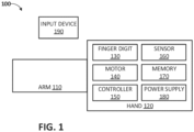
- FIG. 1 illustrates an example block diagram of an example prosthesis 100.
- the prosthesis 100 includes an arm 110 attached to a hand 120.
- the arm 110 may be a prosthetic arm or may be a natural arm, i.e. a natural or sound human arm.
- the arm 110 may be a stump or include a fitting on a distal end thereof.
- the hand 120 may be a prosthetic hand, for example, a full prosthetic hand or a partial prosthetic hand and may include one or more finger digits 130, motors 140, controllers 150, sensors 160, data stores 170, and/or power supplies 180.
- any of the finger digit(s) 130, motor(s) 140, controller(s) 150, sensor(s) 160, data store(s) 170, and/or power supply(ies) 180 can be in electrical communication.
- the controller(s) 150 can communicate with any of the motor(s) 140, sensor(s) 160, data store(s) 170, power supply(ies) 180, and/or input device(s) 190, among other components.
- the finger digit(s) 130, motor(s) 140, controller(s) 150, sensor(s) 160, data store(s) 170, and/or power supply(ies) 180 can be located in a number of locations including any location in or on the arm 110 or hand 120, remote from the arm 100 and hand 120, attached to the wearer of the prosthesis 100 or the like.
- the data store 170 may be combined with controller 150 components to save cost and/or improve performance.
- the prosthesis 100 can include few or more components, as desired, such as one or more input device(s) 190.
- the one or more finger digits 130 can correspond to one or more of an index finger, a middle finger, a ring finger, a pinky finger, or a thumb.
- the hand 120 can include more than four finger digits 130.
- the hand 120 can include fewer than four finger digits 130, for example, where the hand 120 is a partial prosthetic hand.
- the hand 120 can include a structure, such as a palm structure, attaching the one or more finger digits together or with the arm 110.
- the hand 120 may not include a structure, such as a palm structure.
- one or more of the finger digits may connect directly together or connect directly with the arm 110.
- a finger digit 130 corresponding to a thumb can be separate from but attached to a partial prosthetic hand.
- the partial prosthetic hand can attach to a natural, partial hand having one or more natural fingers, which can attach to a natural arm.
- the one or more finger digits 130 can be individually or collectively referred to as a finger digit 130, finger digit(s) 130 or finger digits 130.
- the finger digit 130 can allow for movement in a natural manner and through large or small ranges of motion manner, for example by providing rotation about one or multiple axes, simultaneous rotation about multiple axes, or rotation about one or more moving axes, among other advantages, for example, as further described in the '556 application.
- the prosthesis 100 can include one or more motors for moving the finger digit 130.
- the prosthesis 100 includes a separate motor for each finger digit 130.
- the prosthesis 100 can include a set of one or more separate motors for each finger digit 130.
- the prosthesis 100 can include six motors, such as two motors for a finger digit 130 associated with a thumb and separate motors for each finger digit 130 associated each of the index finger, middle finger, ring finger, and pinky finger.
- the one or more motors of the prosthesis 100 can be individually or collectively referred to as motor 140, motor(s) 140, or motors 140.
- the prosthesis 100 can include or be in communication with one or more sensors 160, which can individually or collectively be referred to as sensor 160, sensor(s) 160, or sensors 160.
- the sensors 160 can capture information relating to position, speed, acceleration, orientation, torque, current, voltage, force, or movement of the prosthesis 100.
- the sensor data may be processed in real-time or near real-time by the sensor(s) 160 or a processing device of the prosthesis 100, such as the controller 150.
- the sensor(s) 160 can include, but are not limited to, a torque sensor, current sensor, voltage sensor, force sensor, acceleration or orientation sensor, or position sensor.
- the sensor(s) 160 can be located in any number of locations in or on the prosthesis 100, in or one a wearer of the prosthesis 100, or remote from the prosthesis 100.
- a torque sensor of the sensors 160 can capture information relating to a torque of a motor 140.
- a current sensor of the sensors 160 can capture information relating to one or more currents flowing through the prosthesis 100, such as a current drawn by a motor 140 or a current flowing from the power supply 180.
- a voltage sensor of the sensors 160 can capture information relating to one or more voltages of the prosthesis 100, such as a voltage received by a motor 140 or a voltage of the power supply 180.
- a torque sensor can be configured to measure a component of force applied to the prosthesis 100 from the ground or other supporting surface in a direction substantially along or parallel to a shin longitudinal axis.
- the force sensor can be implemented as a load cell.
- Data from the sensors 160 can be received by the controller 150 can used to determine various parameters associated with the prosthesis 100, such as a torque of a motor 140 or whether a motor-stall-threshold is satisfied, described further below.
- An acceleration or orientation sensor of the sensors 160 can capture information relating to position, speed, acceleration, or orientation of the prosthesis 100, such as position, speed, acceleration, or orientation data relating to any of the arm 110, the hand 120, or the finger digit 130.
- the acceleration or orientation sensor can capture information corresponding to in multiple axes, such as two or three substantially mutually perpendicular axes.
- the acceleration or orientation sensor can be implemented as one or more of an accelerometer, an orientation sensor, a gravity sensor, or a gyroscope.
- Data from the acceleration or orientation sensor can be received by the controller 150 can used to determine various parameters associated with the prosthesis 100, such as an acceleration of the finger digit 130, a deceleration of the finger digit 130, an orientation of the finger digit 130, an orientation of the prosthesis 100, a torque of a motor 140, a position of the finger digit 130, or the like.
- a force sensor of the sensor(s) 160 can capture information relating to a force applied on or by the finger digit 130.
- the finger digit 130 or portions thereof e.g., finger-pads of the finger digit 130
- the force sensor can be configured to measure a component of force applied to the finger digit 130 by an object or other external force in one or more directions.
- the force sensor 112 can be implemented as a load cell.
- Force measurement data from the force sensor can be received by the controller 150 and can be used to determine various parameters associated with the prosthesis 100, such as a force applied to the finger digit 130, a torque of a motor 140, a position of the finger digit 130, or the like. For example, using the force measurement data, the controller 150 can determine whether the finger digit 130 is touching an object or other opposing force as it is moved by a motor 140.
- a position sensor of the sensor(s) 160 can capture information relating to position of the finger digit 130, such as an absolute position of the finger digit 130.
- the position sensor of the sensor(s) 160 can be implemented as a Hall Effect sensor.
- the motor 140 or the finger digit 130 can include a magnet, such as a magnet about 0.5 to 5 mm in diameter or about 1 mm or 2 mm in diameter, and the magnet may be positioned on a rotating link of the motor 140 or the finger digit 130. As the link rotates, the distance between the magnet and the Hall Effect sensor changes.
- the Hall Effect sensor can sense the magnet, and the Hall Effect sensor can provide signals with different levels of current output depending on the proximity of a magnetic field, which changes as the distance from the magnet changes.
- the controller 150 can use the signals the Hall Effect sensor to determine the angular position of the finger digit 130 or portions thereof.
- a position sensor of the sensor(s) 160 can be implemented as a potentiometer, which may be used to obtain the absolute position of the finger digit 130.
- an incremental optical rotary encoder and/or gyro sensor may be used to control the finger digit 130.
- an incremental optical rotary encoder can generate a signal when a motor 140 moves.
- the motor 140 may include absolute optical encoders.
- the motor 140 may include absolute optical encoders that monitor an internal position of the motor 140.
- the controller 150 can derive the position of the finger digit 130 based at least in part on the motor's rotation.
- Position data from sensor(s) 160 can be received by the controller 150 and can be used to determine various parameters associated with the prosthesis 100, such as an absolute position, a relative position, or an angular position of the finger digit 130.
- the sensor(s) 160 can be located in any one or more locations, including any location in or on the arm 110, hand 120, or remote from the arm 100 or hand 120.
- the prosthesis 100 can include or be in communication with one or more input devices (which can be individually or collectively referred to as input device(s) 190).
- the input device(s) 190 can capture or receive user input and can transmit signals to the prosthesis 100, such as the controller 150, based at least in part on the user input.
- the input device(s) 190 can include one or more myoelectric electrodes.
- a myoelectric electrode can detect electric activity from a muscle of a wearer of the prosthesis 100 (for example, muscles in the wearer's forearm), and the myoelectric electrode can relay information associated with that activity to the controller 150.
- the input device(s) 190 can include a pressure sensitive resistor.
- the input device(s) 190 can detect activity associated with the wearer of the prosthesis 100, such as signals derived from one or more neural implants in the wearer of the prosthesis or orthosis, electromyography (EMG) activity from reinnervated muscles, muscles of the feet and/or chest, or the like.
- EMG electromyography
- the input device(s) 190 can relay information associated with that activity to the controller 150.
- the relayed information can be in the form of one or more activation signals.
- the controller 150 can communicate command signals to the motor(s) 140 based at least in part on the one or more activation signals received from the input device(s) 190.
- the input device(s) 190 can include a switch, such as a toggle switch, a push button switch, a rotary switch, or the like.
- the user can interact with the switch or another input device to control the operation of the prosthesis, such as the movement of the finger digit 130.
- the switch can be toggled or interacted with by a user, causing one or more activation signals to be relayed to the controller 150.
- the controller 150 can communicate command signals to the motor(s) 140 based at least in part on the one or more activation signals received from the input device(s) 190.
- the power supply 180 can be electrically coupled and/or supply power to the motor(s) 140. As described herein, a motor 140 can use energy supplied by the power supply 180 to move a finger digit 130.
- the power supply 180 can include a battery.
- a battery of the power supply 180 can include one or more battery cells arranged in series or parallel, such as, but not limited to, 2, 4, 6, or 8 cells.
- a battery of the power supply 180 can have a high-energy density.
- a battery of the power supply 180 can include Lithium-ion (Li-ion), Lithium Polymer (Li-Pol), or the like. Specifications of the power supply 180 may vary across embodiments.
- a power supply may be selected which fulfills power supply requirements of a motor 140 of the prosthesis 100.
- the power supply 180 can have a nominal voltage between 5 V and 20 V, such as a nominal voltage of 7.4 V.
- the power supply 180 can be appropriately sized or rated based on power supply requirements of prosthesis 100.
- the motor(s) 140 can be a brushed DC motor or a brushless motor. In some cases, the motor(s) 140 can be implemented as an electric rotary actuator. However, other types of motors or actuators may be used without departing from the scope of the description. In some cases, the motor(s) 140 can be controlled using pulse width modulation. For example, the controller 150 can supply or cause another component of the prosthesis 100 to supply a pulse width modulated signal to the motor(s) 140 to control movement of the finger digit(s) 130.
- Each finger digit 130 can include, or be in communication with, one or more motors 140.
- a motor 140 can be configured to move at least a portion of the finger digit 130 about one or more axes.
- FIG. 2A is a perspective view of an example finger digit 130.
- the finger digit 130 is a thumb and includes a lower assembly 202, a middle assembly 204, and an upper assembly 206.
- a motor 140 can cause the upper assembly 206 to rotate about one or more of various axes relative to the lower assembly 202.
- the motor 140 can cause the upper assembly 206 to rotate about a flexion axis 210 (sometimes referred to as a pinch axis).
- the motor 140 can cause the upper assembly 206 to rotate about a rotation axis 220 (sometimes referred to as a lateral axis).
- the flexion axis 210 may be defined and be fixed with respect to portions of the upper assembly 206. Further, the upper assembly 206 may move in directions other than merely rotating about the flexion axis 210. Thus, the orientation of the flexion axis 210 may also change, for example relative to the lower assembly 202, due to movement of the upper assembly 206. The upper assembly may rotate about the flexion axis 210 due at least in part to mechanical communication between various worm gears and worm wheels, as further described below.
- the rotation axis 220 may be defined and be fixed with respect to portions of the lower assembly 202.
- the upper assembly 206 may move in directions other than merely rotating about the flexion axis 210.
- the orientation of the flexion axis 210 may change, for example relative to the lower assembly 202, due to movement of the upper assembly 206.
- the upper assembly 206 may rotate about flexion axis 210, about the rotation axis 220, or about the flexion axis 210 and the rotation axis 220 simultaneously.
- the upper assembly 206 may rotate about the rotation axis 220 due at least part to mechanical communication between worm gears, worm wheels, and bevel gears, as further described below.
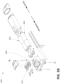
- FIG. 2B is an exploded view of a portion of the upper assembly 206 of the finger digit 130 of FIG. 2A .
- the upper assembly 206 can include a first worm gear 232, a second worm gear 234, a first bevel gear 262, and a second bevel gear 264.
- the worm gears 232, 234 may be rotated by motor(s) 140, such as the first actuator 252 or the second actuator 254, as further described.
- the worm gears 232, 234 mechanically communicate with the worm wheels 242, 244, respectively, of the middle assembly 204.
- Mechanical communication of the worm gear 232 with the worm wheels 242 can cause the upper assembly 206 to rotate about the flexion axis 210.
- Mechanical communication of the worm gear 234 with the worm wheels 244 can cause the upper assembly 206 to rotate about the rotation axis 220.
- Actuation of the first actuator 252 can cause rotation of the upper assembly 206 about the flexion axis 210.
- the first actuator 252 can cause the first worm gear 232 to rotate, and mechanical communication between a rotating first worm gear 232 and the first worm wheel 242 can cause the rotation of the upper assembly 206 about the flexion axis 210. That is, rotation of the first worm gear 232 can cause interaction with the first worm wheel 242. Interaction of gear teeth of the first worm gear 232 with the complementary projections of the first worm wheel 242 cause the first worm gear 232 to advance along the outer circumference of the first worm wheel 242.
- Advancement of the worm gear along the wheel 242 can cause the upper assembly 206 to rotate in a flexion-open or a flexion-closed direction about the flexion axis 210, depending on the direction of rotation of the worm gear 232.
- flexion-open it is meant that the upper assembly 206 moves in a direction associated with extension of the finger digit 130.
- the upper assembly 206 moves in a flexion-open direction or has a flexion-open motion when the upper assembly 206 rotates away from a palm of the hand 120.
- flexion-closed it is meant that the upper assembly 206 moves in a direction associated with flexion of the finger digit 130.
- the upper assembly 206 moves in a flexion-closed direction or has a flexion-closed motion when the upper assembly 206 rotates toward a palm of the hand 120.
- Mechanical communication between the second actuator 254, the second worm gear 234, the second worm wheel 244, and bevel gears 262, 264 allows the upper assembly 206 to rotate about the rotation axis 220.
- actuation of the second actuator 254 can cause rotation of the second worm gear 234.
- the second worm gear 234 includes a series of teeth that interact with a series of projections on the worm wheel 244. Accordingly, rotation of the second worm gear 234 causes rotation of the second worm wheel 244. Because the worm wheel 244 is rotationally fixed with the bevel gear 264, the bevel gear 264 will also rotate and thereby act against the bevel gear 262, which causes the upper assembly 206 to rotate about the rotation axis 220.
- Advancement of the worm gear along the wheel 244 causes the upper assembly 206 to rotate in a rotation-lateral or a rotation-palmer direction about the rotation axis 220, depending on the direction of rotation of the worm gear 234.
- rotation-lateral it is meant that the upper assembly 206 moves in a direction associated with turning away from a palm of the hand 120.
- the upper assembly 206 moves in a rotation-lateral direction or has a rotation-lateral motion when the upper assembly 206 rotates away from a palm of the hand 120.
- rotation-palmer it is meant that the upper assembly 206 moves in a direction associated with turning towards a palm of the hand 120.
- the upper assembly 206 moves in a rotation-palmer direction or has a rotation-palmer motion when the upper assembly 206 rotates toward a palm of the hand 120.
- the first and second actuators 252, 254 can be actuated at distinct time intervals such that the upper assembly 206 rotates about one of the flexion axis 210 or the rotation axis 220.
- the first and second actuators 252, 254 can be actuated at overlapping time intervals, such that the upper assembly 206 can concurrently rotate about both the flexion axis 210 and the rotation axis 220.
- actuation of the first actuator 252 or second actuator 254 may contribute to about one or both the flexion axis 210 and the rotation axis 220.
- FIGS. 2A and 2B illustrates the finger digit 130 as a thumb
- a finger digit 130 can include any of an index finger, a middle finger, a ring finger, or a pinky finger, or a thumb, and any of which may include the same or similar features or functionalities as shown or described with respect to FIGS. 2A and 2B .
- any finger digit 130 can include or be in communication with a motor 140, and the motor 140 can move at least a portion of the finger digit 130 about one or more axes, such as a flexion axis 210 and/or the rotation axis 220.
- other rotations or movements may also be performed by a finger digit 130.
- the finger digit 130 can include other joints along the upper assembly 206 that rotate or move as well.
- the prosthesis 100 can include a clutch assembly -to allow for manual rotation of the upper assembly 206 about the rotation axis 220, for example to prevent damage in case of excessive force applied to the finger digit 130. Additional description and examples of the finger digit 130, such as a thumb, can be found in the ⁇ 556 application.
- the controller 150 can implement an acceleration profile. Implementation of an acceleration profile can advantageously allow the controller 150 to reduce or control an amount of power consumed by a motor 140. In additional or alternatively, implementation of an acceleration profile can advantageously allow the controller 150 to reduce or control an amount of electrical or mechanical noise produced by the motor 140. For example, implementation of an acceleration profile can reduce an amount of power consumed and/or electrical or mechanical noise produced by the motor 140 as the motor 140 accelerates (e.g., as the motor 140 transitions from an idle state, or near-idle state, to a non-idle state). In some cases, the motor 140 is at an idle state when the motor 140 has a duty cycle of 0%, and the motor 140 is at a non-idle state when the motor 140 has a duty cycle above 0%.
- Prior efforts of controlling a motor of a prosthetic hand include initializing the motor to a predetermined duty cycle level (sometimes referred to herein to as the "operating duty cycle").
- a predetermined duty cycle level sometimes referred to herein to as the "operating duty cycle”
- Such an initialization generally includes a binary approach, where the duty cycle of the motor is directly transitioned from an idle state duty cycle (e.g., 0%) to the operating duty cycle, without a duty-cycle ramp-up in between.
- an idle state duty cycle e.g., 0%
- prior efforts would initialize the motor 140 to run at 100% duty cycle, rather than progressively ramping the duty cycle, such as to some smaller duty cycle between 0% duty cycle and 100% duty cycle.
- This method of initializing the motor to the operating duty cycle advantageously allows the motor to achieve a desired speed or perform a desired movement as quickly as possible.
- initializing the motor 140 to the operating duty cycle can introduce electrical and/or mechanical noise into the prosthesis 100, as well as cause the motor to consume a sizable amount of energy from the power supply 180 of the prosthesis 100.
- the motor 140 can consume less energy from the power supply 180. Furthermore, in some instances, the difference in timing between a prosthesis that initializes the motor to the operating duty cycle and a prosthesis 100 that implements the disclosed acceleration profile is not noticeable to human eye. In some cases, the controller 150 can implement an acceleration profile on multiple motors 140 concurrently or sequentially.
- routine 300 can be implemented by one or more computing devices that are associated with the prosthesis 100, such as the controller 150. Accordingly, routine 300 has been logically associated as being generally performed by the controller 150. However, the following illustrative example should not be construed as limiting.
- the controller 150 determines to move the finger digit 130. In some cases, the controller 150 determines to move the finger digit 130 to a new or different position, such as from first position to a second position.
- the determination to move the finger digit 130 can be based at least in part on one or more activation signals.
- the prosthesis 100 can include or be in communication with one or more user input devices 190, such as one or more of a myoelectric electrode, a pressure sensitive resistor, a neural implant, a mechanical switch, or the like.
- the controller 150 can continuously or periodically monitor the user input device(s) 190 or can receive signals from the user input device(s) 190.
- a myoelectric electrode can detect electric activity from a muscle of a wearer of the prosthesis 100, and the myoelectric electrode can relay that information to the controller 150.
- the controller 150 can determine to move the prosthetic finger.
- signals received from the user input device(s) 190 can be activation or instruction signals. Responsive to the controller 150 detecting an activation or an instruction signal, the controller 150 can determine to move the prosthetic finger 130.
- the data store 170 stores an operating profile that includes prosthetic finger manipulation data, such as hand grip identifiers, motor identifies, direction identifiers, or the like, and a plurality of activation or instruction signal identifiers.
- the operating profile can associate the prosthetic finger manipulation data with the each of the activation or instruction signal identifiers such that the controller 150 can determine to move the finger digit 130, identify a motor, or identify a direction to move the finger digit 130 based at least in part on signals received from the user input device(s) 190.
- the determination to move the finger digit 130 can be based at least in part on one or more stored computer executable instructions.
- the data store 170 can store computer executable instructions that, when executed by the controller 150, cause the controller 150 to determine to move the finger digit 130, identify a motor, or identify a direction to move the finger digit 130.
- the controller 150 can select or identify motor(s) 140 to operate in order to achieve a desired movement. For example, the controller 150 controller can select or identify the motor(s) 140 associated with the finger digit 130. In some cases, the selection or identification of the motor(s) 140 is based at least in part on the desired movement, such as a selected hand gesture, a selected hand grip, or the like.
- the data store 170 stores an operating profile that includes a plurality of hand gestures or hand grips and an indication of the motor(s) 140 corresponding to each of the plurality hand gestures or hand grips. The operating profile can associate each of the plurality hand gestures or hand grips with the corresponding motor(s) 140 such that the controller can identify or select the motor(s) 140 from the operating profile based at least in part on a desired hand gesture or hand grip.
- the controller 150 can identify the direction in which a motor 140 is to move the finger digit 130. For example, the controller 150 can identify the flexion-open direction or the flexion-close direction, as described herein. As another example, the controller 150 can identify the rotation-palmer direction or the rotation-lateral direction, as described herein.
- the controller 150 communicates a first command signal.
- the communication of the first command signal can be based at least in part on the determination to move the finger digit 130 at block 302.
- first command signal is a pulse width modulation (PWM) signal to the motor 140.
- PWM pulse width modulation
- the first command signal causes a PWM signal to be transmitted to the motor 140.
- the motor 140 Prior to the communication of the first command signal, the motor 140 can be in an idle state. That is, the motor 140 can have a duty cycle equal to an idle state duty cycle.
- the idle state duty cycle can vary across embodiments. In some instances, the idle state duty cycle can correspond to a 0% duty cycle, which can be equivalent to the motor 140 drawing no or nominal power from the power supply 180.
- the idle state duty cycle can correspond to a higher than zero value, such as a duty cycle value that is low enough so as to not overcome starting friction (sometimes referred to as static friction or stiction) associated with the components of the motor 140.
- a duty cycle value that is low enough so as to not overcome starting friction (sometimes referred to as static friction or stiction) associated with the components of the motor 140.
- starting friction sometimes referred to as static friction or stiction
- an electric motor 140 does not operate (that is, a shaft of the electric motor 140 does not rotate) until power is applied to the electric motor 140.
- the idle state duty cycle can correspond to a duty cycle of the motor 140 that is not large enough to overcome the stiction of the motor 140.
- the idle state duty cycle can be 0%, 1%, 5%, 10%, 15%, 20%, less than 1%, less than 5%, less than 10%, or less than 20%. It will be understood that the idle state duty cycle can be various other duty cycle values as well.
- the first command signal can cause a duty cycle of the motor 140 to increase from the idle state duty cycle to satisfy a first duty cycle level.
- the first duty cycle level can be a duty cycle that is greater than the idle state duty cycle, but less than a second duty cycle level, described herein.
- the first duty cycle level can correspond to the minimum duty cycle of the motor 140 that will allow the motor 140 to overcome the stiction of the motor 140.
- the first duty cycle level can correspond to a duty cycle that is higher than the minimum duty cycle of the motor 140 that will allow the motor 140 to overcome the stiction of the motor 140.
- the first duty cycle level can correspond to a predetermined value or percentage higher than the minimum duty cycle of the motor 140 that will allow the motor 140 to overcome the stiction of the motor 140.
- the first duty cycle level can be 1, 2, 3, 4, 5, 6, 7, 8, 9, or 10% more duty cycle than the minimum duty cycle of the motor 140 that will allow the motor 140 to overcome the stiction of the motor 140. It will be understood that the first duty cycle level can be various other duty cycle values as well.
- the first command signal can cause the motor 140 to initialize directly to the first duty cycle level, such that the motor 140 is transitioned from the idle state duty cycle to the first duty cycle level without a gradual ramp-up period.
- the controller 150 communicates a second command signal.
- the controller 150 can communicate the second command signal after or concurrently with the communication of the first command signal at block 304.
- the second command signal can cause a systematic increase in the duty cycle of the motor 140 from the first duty cycle level to a second duty cycle level.
- the second duty cycle level can correspond to an operating duty cycle level, or the duty cycle at which the motor 140 typically operates for the duration of the movement or for a substantial portion of the movement.
- the systematic increase in the duty cycle can include a gradual or controlled increase in the duty cycle from the first duty cycle level to the second duty cycle level.
- the systematic increase can be a uniform increase from the first duty cycle level to the second duty cycle level.
- the systematic increase can be a non-uniform increase from the first duty cycle level to the second duty cycle level.
- the systematic increase includes a stepwise increase.
- the duty cycle of the motor can be increase in a stepwise pattern from the first duty cycle level to the second duty cycle level, for example, including 5, 8, 10, 12, 15, or 20 "steps" or discrete points in the stepwise pattern.
- the systematic increase, such as the stepwise pattern corresponds to a simple exponential curve, an S-shaped exponential curve, or a J-shaped exponential curve.
- the systematic increase in the duty cycle of the motor 140 from the first duty cycle level to the second duty cycle level can occur over a predetermined duration of time.
- the length of the predetermined duration of time can vary across embodiments.
- the length of the first predetermined duration of time can be 20, 40, 60, 80, 100, 120, or 140 ms (+/- 5 to 10 ms).
- the length of the predetermined duration of time can be between 40 to 160 ms, 60 to 140 ms, or 80 to 120 ms. It will be understood that various other durations can be utilized.
- the systematic increase in the duty cycle of the motor 140 from the first duty cycle level to the second duty cycle level can advantageously allow the prosthesis 100 to conserve energy of the power supply 180 that might otherwise be consumed by the motor 140 if the motor 140 was initialized to the second duty cycle level.
- the length of time added to a particular movement of the prosthesis 100 by implementing an acceleration profile, as described herein can be negligible.
- the addition of the acceleration profile can add less than 100 ms to a movement by the prosthesis 100, such as about 10 ms.
- the various blocks of FIG. 3 can be implemented in a variety of orders, and that the prosthesis 100 can implement one or more of the blocks concurrently and/or change the order, as desired.
- the controller 150 can concurrently communicate the first and second command signals.
- routine 300 can include blocks for communicating another command signal to reduce a duty cycle of the motor.
- routine 300 can implement some or all of various blocks of FIGS. 5A , 5B , 9 , or 10 in routines 500A, 500B, 900, or 1000 concurrently or change the order as desired.
- routine 300 can omit certain blocks, such as, but not limited to, block 302. For example, in some cases, the controller 150 does not determine to move the finger digit 130.
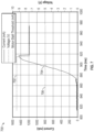
- FIG. 4 is a graph 400 illustrating an example drive profile for a motor that includes an example acceleration profile.
- the horizontal axis on the graph 400 corresponds to time, in milliseconds (ms).
- the vertical axis on the graph 400 corresponds to a voltage, in volts (V), supplied to the motor.
- the vertical axis on the graph 400 corresponds to a current, in milliamps (mA), supplied to the motor.
- the graph 400 illustrates an example systematic increase of the duty cycle of the motor 140 over a 50 ms duration.
- the voltage is systematically increased, such that the shape of the increase corresponds to an S-shaped exponential curve.
- the voltage is systematically increased by increasing the duty cycle every five ms, at least during the first 40 ms.
- the size of the duty cycle increase varies depending on the time. For example, the average duty cycle increase during the 20-50 ms range is larger than the average duty cycle increase during the 0-20 ms time range, which is larger than the average duty cycle increase during the 40-5 ms time range.
- a duration of the acceleration profile can be longer than a duration of the systematic voltage increase and/or a duration of the current spike and decrease.
- the entire graph 400 corresponds to the acceleration profile, which has a duration of 100 ms.
- the voltage is initialized to a 20% duty cycle and is increased to a 100% duty cycle over 50 ms.
- it takes about 80 ms for the current to spike to overcome the stiction and then subsequently reduce.
- the controller 150 can ignore a motor-stall-threshold (described further here) during the duration of the acceleration profile (in this example, 100 ms). For instance, as illustrated in FIG.
- the controller 150 can ignore the motor-stall-threshold during the duration of the acceleration profile.
- the motor(s) 140 can control movement of the finger digit 130.
- a motor 140 can move the finger digit 130 in a flexion-open direction (corresponding to flexion of the finger digit 130) or a flexion-closed direction (corresponding to extension of the finger digit 130).
- the same or a different motor 140 can move the finger digit 130 in rotation-lateral direction (corresponding to an outward rotation of the finger digit 130) or a rotation-palmer direction (corresponding to an inward rotation of the finger digit 130).
- two different motors 140 can move the finger digit 130 concurrently or in sequence.
- one motor 140 can move the finger digit 130 in a flexion-open direction or a flexion-closed direction
- another motor 140 can move the finger digit 130 in a rotation-lateral direction or a rotation-palmer direction.
- the finger digit 130 For each of the flexion-open, rotation-lateral, and rotation-palmer motions, rather than closing upon an object, the finger digit 130 is generally either opening or rotating. Therefore, during any of the flexion-open, rotation-lateral, and rotation-palmer motions, the finger digit 130 is expected to move unimpeded through the motion. That is, to complete the motion, the finger digit 130 is not expected to meet an object or an opposing force along its path, unless or until the finger digit 130 reaches its full range of motion or a mechanical end stop along the axis over which it is traveling.
- a wearer of the prosthesis 100 generally uses the flexion-closed motion to grasp an object or to pinch the finger digit 130 together with another finger digit 130. Therefore, in some cases, during the flexion-closed motion, the finger digit 130 is expected to meet an object or other opposing force along its path. Specifically, in certain cases, with respect to grasping an object, the finger digit 130 is expected to meet the object prior to the finger digit 130 reaching its full range of motion along the flexion axis.
- the controller 150 can operate a motor 140 differently, depending on its movement. For example, if the finger digit 130 meets an object or other opposing force along its path during any of the flexion-open, rotation-lateral, or rotation-palmer motions, the controller 150 can cause the motor 140 to stop moving the finger digit 130, either immediately or shortly thereafter. By causing the motor 140 to stop moving the finger digit 130, the prosthesis 100 can conserve energy of the prosthesis 100. For example, energy consumption can be reduced because the motor 140 does not consume, or consume less, energy once the finger digit 130 meets an object in its path.
- the controller 150 can cause the motor 140 to continue moving the finger digit 130 along the flexion axis, at least for a predetermined duration of time. By continuing to move the finger digit 130 along the flexion axis, the controller 150 can cause the finger digit 130 to increase the force, such as a pinch force, exerted on the object, which can secure a grip on the object.
- the controller 150 can, for a second time, cause the motor 140 to move the finger digit 130 along the flexion axis towards the object, so that the finger digit 130 can further increase the force exerted on the object.
- the controller 150 can drive the motor 140 using a pulsing regime to allow the finger digit 130 to further increase the force exerted on the object.
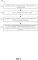
- FIG. 5A is a flow diagram illustrative of an example routine 500 of a prosthesis 100.
- routine 500 can be implemented by one or more computing devices that are associated with the prosthesis 100, such as the controller 150. Accordingly, routine 500 has been logically associated as being generally performed by the controller 150, but the following illustrative example should not be construed as limiting.
- the controller 150 communicates a first command signal to the motor 140 to move the finger digit 130.
- the first command signal can initiate an acceleration profile, as described herein at least with respect to FIG. 3 .
- the first command signal causes the motor 140 to move the finger digit 130 in a flexion-open, rotation-lateral, or rotation-palmer motion.
- the first command signal causes the motor 140 to move the finger digit 130 in a flexion-closed motion.
- the first command signals varies the duty cycle of the motor 140 in proportion to one or more input signals received from an input device(s) 190.
- the motor 140 Prior to receiving the first command signal, the motor 140 can be in an idle state, as described herein. Alternatively, prior to receiving the first command signal, the motor 140 can be in a non-idle state. For example, in some cases, prior to receiving the first command signal, the motor 140 can be moving the finger digit 130 in one or more of a flexion-open, rotation-lateral, rotation-palmer, or flexion-closed motion. In some cases, the first command signal causes the motor 140 to change its direction or motion, or the first command signal can increase or decrease a duty cycle of the motor 140.
- the controller 150 receives a sensor signal from a sensor(s) 160 that corresponds to a torque of the motor 140.
- the sensor(s) 160 can be on or more of various sensors including, but not limited to, one or more torque sensors, current sensors, voltage sensors, force sensors, acceleration or orientation sensors, or position sensors.
- the sensor signal can correspond to or be usable to determine one or more of a torque of the motor 140, a speed of the motor 140, a turning force of the motor 140, a voltage drawn by the motor 140, a current drawn by the motor 140, a force again the finger digit 130, a position of the finger digit 130, or the like.
- the controller 150 determines, based at least in part on the sensor signal, that a motor-stall-threshold is satisfied.
- the motor-stall-threshold corresponds to a stalling of the motor 140, such as when the motor 140 stops rotating or slows in rotation due to a load torque being greater than a shaft torque of the motor 140.
- the motor 140 may draw additional current but motor 140 may not rotate, or may rotate more slowly.
- the motor-stall-threshold corresponds to the finger digit 130 having come in contact with an object or other opposing force along its path of motion.
- the motor-stall-threshold can be satisfied in various ways. For example, to determine whether the motor-stall-threshold is satisfied, the controller 150 can compare a value associated with the sensor signal to one or more thresholds. For example, in some cases, the motor-stall-threshold can be satisfied if any one or more of a torque of the motor 140 satisfies a torque threshold, a current drawn by the motor 140 satisfies a current threshold, a voltage drawn by the motor 140 satisfies a voltage threshold, or a force on the finger digit 130 satisfies a force threshold.
- the motor-stall-threshold can be satisfied based at least in part on a determination that a torque of the motor 140 satisfies a torque threshold. As an example, if the torque of the motor 140 falls below the torque threshold, the torque threshold can be satisfied.
- the torque threshold can vary depending on characteristics of the motor 140, design constraints, or the like. In some cases, the torque threshold is equal to 0 newton-meters (N ⁇ m) or some other torque.
- the motor-stall-threshold can be satisfied based at least in part on a determination that a current drawn by the motor 140 from a power source satisfies a current threshold. As an example, if the current drawn by the motor 140 exceeds the current threshold, the current threshold can be satisfied.
- the current threshold can vary depending on characteristics of the motor 140, design constraints, or the like. In some cases, the current threshold is equal to between 100-900 mA, or some other current.
- the motor-stall-threshold can be satisfied based at least in part on a determination that a force on the finger digit 130 satisfies a force threshold.
- the finger digit 130 can include one or more force sensors, such as capacitive or inductive force sensors. If the force on the finger digit 130 exceeds the force threshold, the force threshold can be satisfied.
- the force threshold can vary across embodiments. For example, the force threshold can be equal to between 5 and 15 N, or some other force.
- the motor-stall-threshold can be satisfied based at least in part on a determination that a speed of the motor 140, or a speed of the finger digit 130, satisfies a speed threshold.
- motor speed for example in revolutions per minute (RPM)
- RPM revolutions per minute
- sensor data such as data from an optical encoder positioned on the motor 140.
- speed threshold can be satisfied.
- the speed threshold can vary across embodiments.
- speed of the finger digit 130 can be determined based on sensor data, such as data from an absolute position sensor placed on the finger digit 130. In some cases, if the speed of the finger digit 130 falls below the speed threshold, the speed threshold can be satisfied.
- the speed threshold can vary across embodiments.
- the routine 500 can include any one or any combination of blocks 508, 510, and/or 512.
- the routine 500 can include block 508.
- the routine 500 can include any one of blocks 510, 512, or 514.
- routine 500 can include any one of blocks 510, 512, or 514, regardless of the direction (e.g., rotation-lateral, rotation-palmer, flexion-open, or flexion-closed) in which the first command signal causes the motor 140 to move.
- direction e.g., rotation-lateral, rotation-palmer, flexion-open, or flexion-closed
- the controller 150 communicates a second command signal to the motor 140 to reduce the duty cycle of the motor 140 to the idle state duty cycle, and the motor 140 returns to an idle state.
- the reduction of the duty cycle of the motor 140 is instantaneous or close to instantaneous.
- the reduction of the duty cycle of the motor 140 to the idle state duty cycle can occur over a duration of less than 5, 10, 15, 20, 25, or 30 ms, or some other duration, from the time at which the controller determines the motor-stall-threshold is satisfied.
- the second command signal can correspond to a removal of the supply of voltage to the motor 140.
- the controller 150 determines that the motor-stall-threshold is not satisfied. For example, the controller 150 can determine that the torque does not satisfy the torque threshold, the current drawn by the motor does not satisfy the current threshold, the voltage by the motor does not satisfy the voltage threshold, or the force on the finger digit 130 does not satisfy the force threshold. In some cases, any one or more of these conditions will cause the motor-stall-threshold to not be satisfied. In some cases, the motor-stall-threshold will not be satisfied when all of these conditions are not satisfied. If the motor-stall-threshold is not satisfied, the controller 150 can end the routine 500A.
- the controller 150 can return to block 504.
- the controller 150 can periodically or continuously receive sensor signals from the sensor(s) 160 or input device(s) 190, can compare values associated with the sensor signals to the one or more threshold to determine whether the motor-stall-threshold is satisfied.
- the blocks of FIG. 5A can be implemented in a variety of orders, and that the prosthesis 100 can implement one or more of the blocks concurrently and/or change the order, as desired. Furthermore, fewer, more, or different blocks can be used as part of the routine 500A.
- the controller 150 can communicate a command signal to reduce the duty cycle until the motor-stall-threshold is no longer satisfied.
- the desired force of the finger digit 130 may be determined or set based at least in part on a strength of an input signal received from an input device(s) 190.
- the controller 150 can communicate a command signal to control the duty cycle of the motor 140 to achieve this desired force. However, based at least in part on a satisfaction of a motor-stall-threshold, the controller 150 can communicate a command signal to reduce the duty cycle of the motor 140, thereby reducing the current consumption such that the motor-stall-threshold is no longer satisfied. The controller 150 can continue to drive the motor 140 at this reduced duty cycle for a duration of time.
- routine 500A can implement some or all of various blocks of FIGS. 3 , 5B , 9 , or 10 in routines 300, 500B, 900, or 1000 concurrently or change the order as desired. Furthermore, the routine 500A can omit certain blocks, such as, but not limited to, block 508. Although routine 500A is generally described with respect to moving a finger digit 130 in a rotation-lateral, rotation-palmer, or flexion-open direction, it will be understood that the routine 500A can be implemented for any movement of the finger digit 130, regardless of the direction (e.g., rotation-lateral, rotation-palmer, flexion-open, or flexion-closed) in which the first command signal causes the motor 140 to move.
- routine 500A is generally described with respect to moving a finger digit 130 in a rotation-lateral, rotation-palmer, or flexion-open direction, it will be understood that the routine 500A can be implemented for any movement of the finger digit 130, regardless of the direction (e.g., rotation-lateral, rotation-palmer,
- two motors 140 can be associated with the same finger digit 130.
- a first motor can move a finger digit 130 in a rotation movement (e.g., any of the rotation-lateral or rotation-palmer directions), while a second motor 140 can move the finger digit 130 in a flexion movement (e.g., in any of the flexion-open or flexion-closed directions).
- each of the first and second motor 140 can concurrently execute routine 500A to cause concurrent rotation and flexion movement of the finger digit 130.
- FIG. 6 is a graph 600 illustrating an example drive profile for a motor 140.
- the horizontal axis on the graph 600 corresponds to time, in ms.
- the vertical axis on the graph 600 corresponds to a voltage (V), in volts, supplied to the motor 140.
- the vertical axis on the graph 600 corresponds to a current, in mA, drawn by the motor 140.
- the graph 600 corresponds to the motor 140 moving a finger digit 130 in any of the rotation-lateral, rotation-palmer, or flexion-open directions.
- prior to time 0, the motor 140 resides in an idle state, having an idle state duty cycle.
- the controller 150 Based at least in part on the motor-stall-threshold being satisfied, the controller 150 causes the duty cycle of the motor 140 to be reduced to the idle state duty cycle, which includes reducing the voltage.
- the motor-stall-threshold may be satisfied.
- the acceleration profile may cause the motor to draw a current that satisfies a current threshold.
- the controller 150 can ignore the motor-stall-threshold and allow the motor 140 to draw sufficient current to accelerate according to an acceleration profile.
- the current increases to approximately 400 mA over the first 50 ms, which can correspond to the motor 140 overcoming a stiction of the motor 140.
- it takes approximately 30 ms for the current consumption to drop to a residual level e.g., lower than approximately 50 mA.
- the controller 150 can ignore the motor-stall-threshold and allow the motor 140 to draw sufficient current to accelerate according to an acceleration profile.
- the controller 150 can continue to monitor the motor-stall-threshold.
- the increase in current towards the end of the graph 600 corresponds to the finger digit 130 stalling against a mechanical end stop of the prosthesis 100.
- the current increases as the motor 140 draws motor current to develop a torque or counteract the opposing force of the mechanical end stop.
- the duty cycle of the motor 140 is reduced to the idle state duty cycle, which includes reducing the current.
- FIG. 5B is a flow diagram illustrative of an example routine 500B of a prosthesis 100.
- routine 500B can be implemented by one or more computing devices that are associated with the prosthesis 100, such as the controller 150. Accordingly, routine 500B has been logically associated as being generally performed by the controller 150, but the following illustrative example should not be construed as limiting.
- the controller 150 communicates a first command signal to cause the motor 140 to move the finger digit 130.
- the controller 150 receives, from sensor(s) 160, a sensor signal that corresponds to a torque of the motor 140.
- the controller 150 determines, based at least in part on the sensor signal received at block 514, that a motor-stall-threshold is satisfied.
- the controller 150 continues to drive the motor 140 for a first predetermined duration of time. After the expiration of the first predetermined duration of time, the controller 150 communicates a third command signal to the motor 140 to reduce the duty cycle of the motor 140 to the idle state duty cycle, and the motor 140 returns to an idle state.
- the controller 150 can communicate a third command signal to the motor 140, which can cause the motor 140 to continue to operate for the first predetermined duration of time and then, after the expiration of the first predetermined duration of time, reduce the duty cycle of the motor 140 to the idle state duty cycle.
- the third command signal can correspond to a removal of the supply of voltage to the motor 140.
- the motor 140 for the first predetermined duration of time can correspond to overdriving the motor 140, which allow the finger digit 130 to exert additional gripping force on an object in its path.
- the motor 140 can consume excessive power, such as excessive current.
- the controller 150 reduces the amount of power consumed while also allowing the finger digit 130 to exert the additional gripping force on the object.
- the duration of the first predetermined duration of time can vary.
- the duration of the first predetermined duration of time can be between 10-140 ms, or some other duration. It will be understood that various other durations for the first predetermined duration of time can be utilized.
- the controller can monitor or receive a second sensor signal from a second sensor, such as a myoelectric electrode 292 or other sensor that can be controlled by the wearer of the prosthesis 100.
- a second sensor such as a myoelectric electrode 292 or other sensor that can be controlled by the wearer of the prosthesis 100.
- the controller 150 can communicate a fourth command signal to the motor 140.
- the fourth command signal can cause the finger digit 130 to further increase its gripping force on the object.
- the fourth command signal can cause the motor 140 to continue to move in the direction it was moving at block 510.
- the second sensor signal corresponds to the wearer of the prosthesis 100 engaging an EMG signal for a second predetermined duration of time.
- the communication of a fourth command signal to the motor 140 is further based at least in part on the user engaging the EMG signal for the second predetermined duration of time.
- the duration of the second predetermined duration of time can vary across embodiments.
- the duration of the second predetermined duration of time can be between 200-800 ms, or some other duration. It will be understood that various other durations for the second predetermined duration of time can be utilized.
- the fourth command signal causing the motor 140 to operate in a cyclic or pulsing regime for a third predetermined duration of time.
- communicating the fourth command signal to the motor 140 can include supplying voltage to the motor 140 to drive the motor 140 in a cyclic or pulsing regime.
- the pulsing regime can correspond to being ON for 5 to 20 ms, then off for 5 to 20 ms.
- the pulsing regime can correspond to being ON for 14 ms, then off for 16 ms. It will be understood that various other durations for a pulsing regime can be implemented.
- the duration of the third predetermined duration of time can vary across embodiments.
- the duration of the third predetermined duration of time can be between 0.6 to 1.4 seconds, or some other duration. It will be understood that various other durations for the third predetermined duration of time can be utilized.
- the controller 150 determines that the motor-stall-threshold is not satisfied. For example, the controller 150 can determine that the torque does not satisfy the torque threshold, the current drawn by the motor does not satisfy the current threshold, the voltage by the motor does not satisfy the voltage threshold, or the force on the finger digit 130 does not satisfy the force threshold. In some cases, any one or more of these conditions will cause the motor-stall-threshold to not be satisfied. In some cases, the motor-stall-threshold will not be satisfied when all of these conditions are not satisfied. If the motor-stall-threshold is not satisfied, the controller 150 can end the routine 500.
- the controller 150 can return to block 504.
- the controller 150 can periodically or continuously receive sensor signals from the sensor(s) 160 or input device(s) 190, can compare values associated with the sensor signals to the one or more threshold to determine whether the motor-stall-threshold is satisfied.
- the blocks of FIG. 5B can be implemented in a variety of orders, and that the prosthesis 100 can implement one or more of the blocks concurrently and/or change the order, as desired.
- fewer, more, or different blocks can be used as part of the routine 500B.
- the routine 500B can implement some or all of various blocks of FIGS. 3 , 5A , 9 , or 10 in routines 300, 500A, 900, or 1000 concurrently or change the order as desired.
- the routine 500B can omit certain blocks, such as, but not limited to, blocks 518, 520, or 522.
- routine 500B is generally described with respect to moving a finger digit 130 in a flexion-closed direction, it will be understood that the routine 500B can be implemented for any movement of the finger digit 130, regardless of the direction (e.g., rotation-lateral, rotation-palmer, flexion-open, or flexion-closed) in which the first command signal causes the motor 140 to move.
- direction e.g., rotation-lateral, rotation-palmer, flexion-open, or flexion-closed
- two motors 140 can be associated with the same finger digit 130.
- a first motor can move a finger digit 130 in a rotation movement (e.g., any of the rotation-lateral or rotation-palmer directions), while a second motor 140 can move the finger digit 130 in a flexion movement (e.g., in any of the flexion-open or flexion-closed directions).
- each of the first and second motor 140 can concurrently execute routine 500B to cause concurrent rotation and flexion movement of the finger digit 130.
- FIG. 7 is a graph 700 illustrating example voltages and currents of a motor 140 during an overdriving period.
- the horizontal axis on the graph 700 corresponds to time, in ms.
- the vertical axis on the graph 700 corresponds to a voltage (V), in volts, supplied to the motor.
- the vertical axis on the graph 700 corresponds to a current, in mA, drawn by the motor 140.
- the graph 700 corresponds to the motor 140 moving a finger digit 130 in a flexion-closed direction. In some cases, the graph 700 corresponds to the motor 140 moving a finger digit 130 in any of a rotation-lateral, rotation-palmer, or flexion-open direction.
- the controller 150 continues to drive the motor 140 for a predetermined duration of time, which in this example is 80 ms. In some cases, this overdriving period of the motor 140 is used to allow the finger digit 130 to exert additional force on gripped objects.
- the controller 150 can cease the supply of voltage to the motor 140, at least for a predetermined duration. Furthermore, the controller 150 can monitor an input device(s) 190 and/or receive a signal from input device(s) 190. In some cases, based at least in part on the monitoring and/or the input signal, the controller 150 can cause the motor 140 to move to cause the finger digit 130 to exert additional force.
- the input device(s) 190 can be a myoelectric electrode, and if the user continues to engage an EMG signal for a predetermined duration of time, the controller 150 can pulse the motor 140 to allow the finger digit 130 to exert additional force.
- FIG. 8 is a graph 800 illustrating an example drive profile for a motor 140 that includes an acceleration profile, an overdriving period, and an exertion of extra force.
- the horizontal axis on the graph 800 corresponds to time, in ms.
- the vertical axis on the graph 800 corresponds to a voltage (V), in volts, supplied to the motor 140.
- the vertical axis on the graph 600 corresponds to a current, in mA, drawn by the motor 140.
- the graph 700 corresponds to the motor 140 moving a finger digit 130 in a flexion-closed direction.
- the graph 800 corresponds to the motor 140 moving a finger digit 130 in any of a rotation-lateral, rotation-palmer, or flexion-open direction.
- the controller 150 continues to drive the motor 140 for a first predetermined duration of time, referred to as the overdriving period, which allows the finger digit 130 to exert additional force to further grip objects.
- the controller 150 ceases the supply of voltage to the motor 140 and monitors an input device(s) 190, such as a myoelectric electrode. At 808, the controller 150 determines, based at least in part on an input signal of the input device(s) 190, to provide a series of pulses to the motor 140 to allow the finger digit 130 to exert additional force. After a predetermined duration of time of providing the pulses, the controller 150 ceases the supply of voltage to the motor 140.
- a finger digit can be screwed into or otherwise attached into a knuckle block in a manner such that a range of motion of the finger digit (for example, along a flexion axis or rotation axis) is restricted between a fully-open and a fully-closed position.
- a range of motion of the finger digit for example, along a flexion axis or rotation axis
- the mechanics of the finger digit and the mechanics of the knuckle block can meet each other such that the finger digit reaches (and it stopped by) a mechanical end stop at each of the fully-open and fully-closed positions.
- a controller can become unaware of the exact positioning of a finger digit as the finger digit is moved by the motor.
- the motor can move the finger digit until the finger digit is stopped by a mechanical end stop (e.g., corresponding to a fully-open position), at which time the controller can determine the position of the finger digit based at least in part on a known location of the mechanical end stop.
- a starting position of the finger digit may be known or determined, for example, based at least in part on the finger digit's proximity to another mechanical end stop (e.g., corresponding to a fully-closed position).
- the controller may be unaware of the exact positioning of the finger digit as it moved between mechanical end stops.
- the position of the finger digit is estimated, for example, based at least in part on a duty cycle of the motor or a time over which the finger digit is moved.
- these estimations can be misleading and can cause the finger digit to be placed in an unintended position.
- engineering tolerances in the manufacturing can result in varying levels of internal resistance of the prosthetic hand, such as within the motor or the finger digit.
- accelerations or speeds of different finger digits can vary and estimations can be difficult or inaccurate.
- mechanical components of the prosthetic hand can wear down over time, which can cause a change in the internal resistive forces of the prosthetic hand, thereby causing changes in acceleration or speed of the finger digit and making estimations difficult or inaccurate.
- dirt, grime, etc. can become lodged within the mechanics of the finger digit, which can reduce the acceleration or speed of the finger digit, thereby making estimations difficult or inaccurate.
- Systems, routines and methods disclosed herein can implement a deceleration profile, which can cause the finger digit 130 to decelerate as it approaches a desired position or a mechanical end-stop.
- the implementation of a deceleration profile can reduce an amount of power consumed by a motor 140 as the motor 140 transitions from a non-idle state, for example where the motor 140 has some value of duty cycle above 0%, to an idle state, for example where the motor 140 has a duty cycle of 0%.
- a controller 150 can determine to move the finger digit 130 from a first position to a second position, and can monitor a position of the finger digit 130 as it moves from the first position to the second position.
- the controller 150 can implement the deceleration profile, which can cause the systematic deceleration of the finger digit 130 until the finger digit 130 reaches the second position, at which time the duty cycle of the motor can be reduced to an idle state duty cycle.
- the controller 150 can implement a deceleration profile on multiple motors 140 concurrently or sequentially.
- FIG. 9 is a flow diagram illustrative of a routine 900 for an example deceleration profile implemented by a prosthesis 100 on a motor 140 that is configured to move a finger digit of the prosthesis 100.
- the elements outlined for routine 900 can be implemented by one or more computing devices that are associated with the prosthesis 100, such as the controller 150. Accordingly, routine 900 has been logically associated as being generally performed by the controller 150. However, the following illustrative example should not be construed as limiting.
- the controller 150 determines to move the finger digit 130 from a first position to a second position.
- the controller 150 receives a sensor signal from a sensor(s) 160.
- the sensor(s) 160 can capture information relating to, among other things, position or movement of the motor 106 or the finger digit 130, and the sensor signal can correspond to some or all of this information.
- the sensor 130 can correspond to a position sensor, such as a Hall Effect sensor or a rotary encoder, as described herein.
- the controller 150 determines, based at least in part on the sensor signal, that the finger digit 130 satisfies a location threshold. For example, as the motor 140 moves the finger digit 130 from the first position (e.g., the starting position of the finger digit 130) to the second position (e.g., the desired ending position of the finger digit 130), the controller 150 can utilize the sensor signal received at block 906 to determine the real-time position of the finger digit 130, such as an absolute position, a relative position, or an angular position of the finger digit.
- the location threshold can correspond to a third position of the finger digit 130, which can be a position located between the first position and the second position. For example, based at least in part on a determination that the finger digit 130 has reached or is at the third position, the controller 150 can determine that the location threshold is satisfied.
- the location threshold can correspond to a position with respect to the second position.
- the location threshold can be a certain distance or a particular angular distance away from the second position.
- the controller 150 can determine that the location threshold is satisfied.
- the controller 150 communicates a command signal to systematically reduce a duty cycle of the motor to an idle state duty cycle.
- the communication of the command signal can be based at least in part on the determination that the finger digit 130 satisfies the location threshold.
- the systematic decrease in the duty cycle can include a gradual or controlled decrease in the duty cycle to the idle state duty cycle.
- the systematic decrease can be a uniform decrease to the idle state duty cycle.
- the systematic decrease can be non-uniform decrease to the idle state duty cycle.
- the systematic decrease includes a stepwise decrease.
- the duty cycle of the motor can be decreased in a stepwise pattern from its operating duty cycle to the idle state duty cycle, for example, including 5, 8, 10, 12, 15, or 20 "steps" or discrete points in the stepwise pattern.
- the systematic decrease, such as the stepwise pattern corresponds to a reverse S-shaped exponential curve or a reverse J-shaped exponential curve.
- the systematic decrease in the duty cycle of the motor 140 to the idle state duty cycle can occur over a predetermined duration of time.
- the length of the predetermined duration of time can vary across embodiments.
- the length of the first predetermined duration of time can be between 20-140 ms, or some other duration. It will be understood that various other durations can be utilized.
- the various blocks of FIG. 9 can be implemented in a variety of orders, and that the prosthesis 100 can implement one or more of the blocks concurrently and/or change the order, as desired.
- the routine 900 can include blocks for implementing an acceleration profile, as described herein.
- the controller 150 can communicate another command signal. Similar to as described in block 304 of FIG. 3 , prior to the communication of another command signal, the motor 140 can be in an idle state. Furthermore, similar to as described in block 304 of FIG. 3 , the command signal can cause a duty cycle of the motor 140 to increase from the idle state duty cycle to some value of duty cycle above 0%.
- the another command signal can cause a duty cycle of the motor 140 to increase from the idle state duty cycle to satisfy a first duty cycle level that allows the motor 140 to overcome the stiction of the motor 140, and the another command signal can further cause a systematic increase in the duty cycle of the motor 140 from the first duty cycle level to another duty cycle level.
- the controller 150 can communicate another command signal to vary the duty cycle of the motor in proportion to one or more sensor signals received from a myoelectric sensor. In some cases, based on a determination that a motor-stall-threshold is satisfied, the controller 150 can communicate a command signal to reduce the duty cycle until the motor-stall-threshold is no longer satisfied. For example, the desired force of the finger digit 130 may be determined or set based at least in part on a strength of an input signal received from an input device(s) 190. In some cases, the controller 150 can communicate a command signal to control the duty cycle of the motor 140 to achieve this desired force.
- the controller 150 can communicate a command signal to reduce the duty cycle of the motor 140, thereby reducing the current consumption such that the motor-stall-threshold is no longer satisfied.
- the controller 150 can continue to drive the motor 140 as this reduced duty cycle for a duration of time.
- routine 900 can implement some or all of various blocks of FIGS. 3 , 5A , 5B , or 10 in routines 300, 500A, 500B, or 1000 concurrently or change the order as desired. Furthermore, the routine 900 can omit certain blocks, such as, but not limited to, blocks 902, 904, 906, or 908. For example, in some cases, the controller 150 does not determine to move the finger digit 130.
- two motors 140 can be associated with the same finger digit 130.
- a first motor can move a finger digit 130 in a rotation movement (e.g., any of the rotation-lateral or rotation-palmer directions), while a second motor 140 can move the finger digit 130 in a flexion movement (e.g., in any of the flexion-open or flexion-closed directions).
- each of the first and second motor 140 can concurrently execute routine 900 to cause concurrent rotation and flexion movement of the finger digit 130.
- FIG. 10 is a flow diagram illustrative of a routine 1000 for an example acceleration and deceleration profile implemented by a prosthesis 100 on a motor 140 that is configured to move a finger digit of the prosthesis 100.
- routine 1000 can be implemented by one or more computing devices that are associated with the prosthesis 100, such as the controller 150. Accordingly, routine 1000 has been logically associated as being generally performed by the controller 150. However, the following illustrative example should not be construed as limiting.
- the controller 150 receives first signals from an input device(s) 190.
- the first signals are received from a myoelectric electrode.
- a myoelectric electrode can detect electric activity from a muscle of a wearer of the prosthesis 100, and the myoelectric electrode can relay that information to the controller 150.
- the controller 150 determines to move a finger digit 130 from a first position to a second position.
- the controller 150 communicates a first command signal to alter a duty cycle of a motor to satisfy a first duty cycle level.
- the controller 150 communicates a second command signal to systematically increase the duty cycle of the motor over a first predetermined duration of time to satisfy a second duty cycle level.
- the controller 150 communicates a third command signal to vary the duty cycle of the motor in proportion to one or more of the first sensor signals received from the myoelectric sensor.
- the controller 150 receives second sensor signals from a second sensor(s) 160.
- the second sensor(s) 160 can capture information relating to, among other things, position or movement of the motor 106 or the finger digit 130, and the second sensor signals can correspond to some or all of this information.
- the second sensor 130 can correspond to a position sensor, such as a Hall Effect sensor or a rotary encoder, as described herein.
- the controller 150 determines, based at least in part on the second sensor signals, that the finger digit 130 satisfies a location threshold.
- the controller 150 communicates a fourth command signal to systematically reduce a duty cycle of the motor to an idle state duty cycle.
- the various blocks of FIG. 10 can be implemented in a variety of orders, and that the prosthesis 100 can implement one or more of the blocks concurrently and/or change the order, as desired.
- the controller 150 can receive the first or second sensor signals at any point during routine 1000.
- fewer, more, or different blocks can be used as part of the routine 1000.
- the routine 1000 can implement some or all of various blocks of FIGS. 3 , 5A , 5B , or 9 in routines 300, 500A, 500B, or 900 concurrently or change the order as desired.
- the routine 1000 can omit certain blocks, such as, but not limited to, blocks 1002, 1004, 1010, or 1012.
- two motors 140 can be associated with the same finger digit 130.
- a first motor can move a finger digit 130 in a rotation movement (e.g., any of the rotation-lateral or rotation-palmer directions), while a second motor 140 can move the finger digit 130 in a flexion movement (e.g., in any of the flexion-open or flexion-closed directions).
- each of the first and second motor 140 can concurrently execute routine 1000 to cause concurrent rotation and flexion movement of the finger digit 130.
- FIG. 11 is a graph 1100 illustrating an example drive profile for a motor 140 that includes an acceleration profile and a deceleration profile.
- the horizontal axis on the graph 1100 corresponds to time, in ms.
- the vertical axis on the graph 1100 corresponds to a voltage (V), in volts, supplied to the motor 140.
- the vertical axis on the graph 1100 corresponds to a current, in mA, drawn by the motor 140.
- the graph 1100 corresponds to the motor 140 moving a finger digit 130 in a flexion-closed direction.
- the graph 1100 corresponds to the motor 140 moving a finger digit 130 in any of a rotation-lateral, rotation-palmer, or flexion-open direction.
- the finger digit 130 is accelerated by systematically increasing the voltage supplied to the motor 140 until the motor 140 reaches a 100% duty cycle. In the illustrated example, after the finger digit is accelerated, the voltage remains constant for a duration of time until the duty cycle of the motor 140 is systematically decreased by the controller 150 to 0%.
- the controller 150 can determine to systematically decrease the duty cycle of the motor 140 based on a determination that a position of the finger digit 130 satisfies a position threshold. For example, in the illustrated example, using data from a position sensor, the controller 150 determined that the finger digit 130 satisfied the position threshold and, based on that determination, initiated a deceleration profile, as described herein. In some cases, at the end of the deceleration profile, the finger digit 130 is located at a mechanical end-stop. As illustrated by a comparison to FIG. 8 , the drive profile of FIG. 11 advantageously increases an energy efficiency of the prosthesis 100 by reducing an amount of energy consumed by the motor 140 as the motor 140 nears the mechanical end-stop.
- FIG. 12 is a graph 1200 illustrating an example drive profile for a motor 140.
- the horizontal axis on the graph 1200 corresponds to time, in ms.
- the vertical axis on the graph 1200 corresponds to a voltage (V), in volts, supplied to the motor 140.
- the vertical axis on the graph 1200 corresponds to a current, in mA, drawn by the motor 140.
- the graph 1200 corresponds to the motor 140 moving a finger digit 130 in a flexion-closed direction.
- the graph 1200 corresponds to the motor 140 moving a finger digit 130 in any of a rotation-lateral, rotation-palmer, or flexion-open direction.
- prior to time 0, the motor 140 resides in an idle state, having an idle state duty cycle.
- the motor 140 is initialized to start at a first duty cycle level.
- the finger digit 130 is accelerated by systematically increasing the duty cycle of the motor from the first duty cycle level to a second duty cycle level.
- the current starts to increase, for example, responsive to the finger digit 130 contacting an object.
- the controller 150 can determine that a motor-stall-threshold is satisfied.
- the controller 150 communicates a command signal to reduce the duty cycle until the motor-stall-threshold is no longer satisfied. This allows the motor 140 to continue to run for a duration of time, without consuming as much energy as if the motor 140 was operated at 100% duty cycle. Nonetheless, by continuing the provide the motor 140 a duty cycle greater than a 0% duty cycle, the motor 140 continues to the move the finger digit 130, which further increases a force grip of the finger digit 130 on the object.
- the controller 150 causes the end of the supply of voltage to the motor 140 and monitors an input device(s) 190, such as a myoelectric electrode. At 1208, the controller 150 determines, based at least in part on an input signal from the input device(s) 190, to provide a series of pulses to the motor 140 to allow the finger digit 130 to exert additional force. After a predetermined duration of time of providing the pulses, the controller 150 ceases the supply of voltage to the motor 140.
- each embodiment of this invention may include, additional to its essential features described herein, one or more features as described herein from each other embodiment of the invention disclosed herein.
- Conditional language such as “can,” “could,” “might,” or “may,” unless specifically stated otherwise, or otherwise understood within the context as used, is generally intended to convey that certain cases include, while other embodiments do not include, certain features, elements, and/or steps. Thus, such conditional language is not generally intended to imply that features, elements, and/or steps are in any way required for one or more embodiments or that one or more embodiments necessarily include logic for deciding, with or without user input or prompting, whether these features, elements, and/or steps are included or are to be performed in any particular embodiment.
- the terms “generally parallel” and “substantially parallel” refer to a value, amount, or characteristic that departs from exactly parallel by less than or equal to 15 degrees, 10 degrees, 5 degrees, 3 degrees, 1 degree, 0.1 degree, or otherwise.
Landscapes
- Health & Medical Sciences (AREA)
- Engineering & Computer Science (AREA)
- Transplantation (AREA)
- General Health & Medical Sciences (AREA)
- Orthopedic Medicine & Surgery (AREA)
- Vascular Medicine (AREA)
- Animal Behavior & Ethology (AREA)
- Cardiology (AREA)
- Biomedical Technology (AREA)
- Heart & Thoracic Surgery (AREA)
- Veterinary Medicine (AREA)
- Life Sciences & Earth Sciences (AREA)
- Oral & Maxillofacial Surgery (AREA)
- Public Health (AREA)
- Robotics (AREA)
- Mechanical Engineering (AREA)
- Nonlinear Science (AREA)
- Physics & Mathematics (AREA)
- Power Engineering (AREA)
- Prostheses (AREA)
Description
- The present disclosure relates to prosthetics. More specifically, this disclosure relates to systems, methods, and apparatuses for reducing electrical noise and/or reducing energy consumption in a motor-driven digit of a prosthesis.
- Over the years, many kinds of prostheses have been devised in effort to replace the limbs that amputees have lost. In particular, efforts have been made to develop prostheses that will replace the loss of major limbs such as legs and arms in view of the immense impact that such a loss has on the amputee. The loss of upper limbs creates particular challenges due to the intricacy and dexterity of the human hand.
- To that end, electric motors have been incorporated into some prostheses to facilitate movements of one or more of the digits, such as prosthetic thumbs or fingers. However, an electric motor can introduce undesirable electrical noise into an associated prosthesis. Furthermore, an electric motor can consume a significant amount of energy. Improvements in this area are therefore desirable.
-
US 2012/221122 which prior art closest to the present invention discloses a method of controlling a movable component of a prosthesis or orthosis. The method comprises moving the component by means of a motor and determining when movement of the component is arrested when the component bears against a surface. Thereafter a plurality of driving electrical pulses are applied to the motor in dependence on the determination and when movement of the component is arrested to thereby drive the motor so as to cause the component to bear against the surface with greater force. - The following disclosure describes non-limiting examples of some embodiments. For instance, other embodiments of the disclosed systems and methods may or may not include the features described herein. Moreover, disclosed advantages and benefits can apply only to certain cases of the invention and should not be used to limit the disclosure. The embodiments disclosed herein each have several aspects no single one of which is solely responsible for the disclosure's desirable attributes.
- The present disclosure describes example systems, methods, and apparatuses for increasing power efficiency of a prosthetic hand without significantly reducing the speed at which it operates. A prosthesis can implement an acceleration profile, which can reduce an energy consumption of a motor, or an amount of electrical and/or mechanical noise produced by a motor, as the motor as the motor transitions from an idle state to a non-idle state. A prosthesis can implement a deceleration profile, which can reduce the energy consumption of the motor, or an amount of electrical and/or mechanical noise produced by a motor, as the motor transitions from a non-idle state to an idle state.
-
-
FIG. 1 illustrates a block diagram of an example prosthesis. -
FIG. 2A is a perspective view of an example finger digit. -
FIG. 2B is an exploded view of a portion of the upper assembly of the finger digit ofFIG. 2A -
FIG. 3 is a flow diagram illustrative of a routine for an example acceleration profile implemented by a prosthesis on a motor that is configured to move a finger digit of the prosthesis. -
FIG. 4 is a graph illustrating an example drive profile for a motor that includes an example acceleration profile. -
FIG. 5A is a flow diagram illustrative of an example routine of a prosthesis. -
FIG. 5B is a flow diagram illustrative of an example routine of a prosthesis. -
FIG. 6 is a graph illustrating an example drive profile for a motor. -
FIG. 7 is a graph illustrating example voltages and currents of a motor during an overdriving period. -
FIG. 8 is a graph illustrating an example drive profile for a motor that includes an acceleration profile, a overdriving period, and an exertion of extra force. -
FIG. 9 is a flow diagram illustrative of a routine for an example deceleration profile implemented by a prosthesis on a motor that is configured to move a finger digit of the prosthesis. -
FIG. 10 is a flow diagram illustrative of a routine for an example acceleration and deceleration profile implemented by a prosthesis on a motor that is configured to move a finger digit of the prosthesis. -
FIG. 11 is a graph illustrating an example drive profile for a motor that includes an acceleration profile and a deceleration profile. -
FIG. 12 is a graph illustrating an example drive profile for a motor that includes an acceleration profile, a deceleration profile, an overdriving period, and the exertion of extra force. - Although certain cases and examples are described below, it will be understood that the disclosure extends beyond the specifically disclosed embodiments and/or uses and obvious modifications and equivalents thereof. Thus, it is intended that the scope of the disclosure herein disclosed should not be limited by any particular embodiments described below.
- Amputees prefer prosthetic hands that have a long battery life and that mimic, as close as possible, the natural movement of a sound hand, including the speed at which a sound hand can react or move into a particular hand grip. However, in general, the battery life of a prosthetic hand is inversely related to the speeds of the motors of the prosthetic hand. Accordingly, it can be difficult to navigate the compromise between a speed of the prosthetic hand and its power consumption.
- Routines and methods disclosed herein can increase a power efficiency of a prosthetic hand without significantly reducing the speed at which it operates. For example, routines and methods disclosed herein can implement an acceleration profile, which can reduce the energy consumption of a motor as the motor transitions from an idle state to a non-idle state. As another example, routines and methods disclosed herein can implement a deceleration profile, which can reduce the energy consumption of a motor as the motor transitions from a non-idle state to an idle state. Furthermore, in some cases, routines and methods disclosed herein can reduce an amount of electrical and/or mechanical noise produced by a motor as the motor transitions from an idle state to a non-idle state or a non-idle state to an idle state.
-
FIG. 1 illustrates an example block diagram of anexample prosthesis 100. In the illustrated example, theprosthesis 100 includes anarm 110 attached to ahand 120. Thearm 110 may be a prosthetic arm or may be a natural arm, i.e. a natural or sound human arm. Alternatively, thearm 110 may be a stump or include a fitting on a distal end thereof. Thehand 120 may be a prosthetic hand, for example, a full prosthetic hand or a partial prosthetic hand and may include one ormore finger digits 130,motors 140,controllers 150,sensors 160,data stores 170, and/orpower supplies 180. - Any of the finger digit(s) 130, motor(s) 140, controller(s) 150, sensor(s) 160, data store(s) 170, and/or power supply(ies) 180 can be in electrical communication. For example, the controller(s) 150 can communicate with any of the motor(s) 140, sensor(s) 160, data store(s) 170, power supply(ies) 180, and/or input device(s) 190, among other components. Depending on the embodiment, the finger digit(s) 130, motor(s) 140, controller(s) 150, sensor(s) 160, data store(s) 170, and/or power supply(ies) 180 can be located in a number of locations including any location in or on the
arm 110 orhand 120, remote from thearm 100 andhand 120, attached to the wearer of theprosthesis 100 or the like. Furthermore, it will be understood that some of these separate components may be combined in a variety of ways to achieve particular design objectives. For example, In some cases, thedata store 170 may be combined withcontroller 150 components to save cost and/or improve performance. Furthermore, theprosthesis 100 can include few or more components, as desired, such as one or more input device(s) 190. - The one or
more finger digits 130 can correspond to one or more of an index finger, a middle finger, a ring finger, a pinky finger, or a thumb. In some cases, thehand 120 can include more than fourfinger digits 130. In some cases, thehand 120 can include fewer than fourfinger digits 130, for example, where thehand 120 is a partial prosthetic hand. In instances such as these, thehand 120 can include a structure, such as a palm structure, attaching the one or more finger digits together or with thearm 110. In some cases, thehand 120 may not include a structure, such as a palm structure. For example, one or more of the finger digits may connect directly together or connect directly with thearm 110. In some cases, afinger digit 130 corresponding to a thumb can be separate from but attached to a partial prosthetic hand. The partial prosthetic hand can attach to a natural, partial hand having one or more natural fingers, which can attach to a natural arm. The one ormore finger digits 130 can be individually or collectively referred to as afinger digit 130, finger digit(s) 130 orfinger digits 130. - The
finger digit 130 can allow for movement in a natural manner and through large or small ranges of motion manner, for example by providing rotation about one or multiple axes, simultaneous rotation about multiple axes, or rotation about one or more moving axes, among other advantages, for example, as further described in the '556 application. - Returning to
FIG. 1 , theprosthesis 100 can include one or more motors for moving thefinger digit 130. For example, in some cases, theprosthesis 100 includes a separate motor for eachfinger digit 130. As another example, theprosthesis 100 can include a set of one or more separate motors for eachfinger digit 130. Still, as another example, theprosthesis 100 can include six motors, such as two motors for afinger digit 130 associated with a thumb and separate motors for eachfinger digit 130 associated each of the index finger, middle finger, ring finger, and pinky finger. The one or more motors of theprosthesis 100 can be individually or collectively referred to asmotor 140, motor(s) 140, ormotors 140. - The
prosthesis 100 can include or be in communication with one ormore sensors 160, which can individually or collectively be referred to assensor 160, sensor(s) 160, orsensors 160. Thesensors 160 can capture information relating to position, speed, acceleration, orientation, torque, current, voltage, force, or movement of theprosthesis 100. The sensor data may be processed in real-time or near real-time by the sensor(s) 160 or a processing device of theprosthesis 100, such as thecontroller 150. The sensor(s) 160 can include, but are not limited to, a torque sensor, current sensor, voltage sensor, force sensor, acceleration or orientation sensor, or position sensor. The sensor(s) 160 can be located in any number of locations in or on theprosthesis 100, in or one a wearer of theprosthesis 100, or remote from theprosthesis 100. - A torque sensor of the
sensors 160 can capture information relating to a torque of amotor 140. A current sensor of thesensors 160 can capture information relating to one or more currents flowing through theprosthesis 100, such as a current drawn by amotor 140 or a current flowing from thepower supply 180. A voltage sensor of thesensors 160 can capture information relating to one or more voltages of theprosthesis 100, such as a voltage received by amotor 140 or a voltage of thepower supply 180. - A torque sensor can be configured to measure a component of force applied to the
prosthesis 100 from the ground or other supporting surface in a direction substantially along or parallel to a shin longitudinal axis. In some cases, the force sensor can be implemented as a load cell. - Data from the
sensors 160 can be received by thecontroller 150 can used to determine various parameters associated with theprosthesis 100, such as a torque of amotor 140 or whether a motor-stall-threshold is satisfied, described further below. - An acceleration or orientation sensor of the
sensors 160 can capture information relating to position, speed, acceleration, or orientation of theprosthesis 100, such as position, speed, acceleration, or orientation data relating to any of thearm 110, thehand 120, or thefinger digit 130. In some instances, the acceleration or orientation sensor can capture information corresponding to in multiple axes, such as two or three substantially mutually perpendicular axes. In some cases, the acceleration or orientation sensor can be implemented as one or more of an accelerometer, an orientation sensor, a gravity sensor, or a gyroscope. - Data from the acceleration or orientation sensor can be received by the
controller 150 can used to determine various parameters associated with theprosthesis 100, such as an acceleration of thefinger digit 130, a deceleration of thefinger digit 130, an orientation of thefinger digit 130, an orientation of theprosthesis 100, a torque of amotor 140, a position of thefinger digit 130, or the like. - A force sensor of the sensor(s) 160 can capture information relating to a force applied on or by the
finger digit 130. For example, thefinger digit 130 or portions thereof (e.g., finger-pads of the finger digit 130) can be fitted with capacitive or inductive force sensors. The force sensor can be configured to measure a component of force applied to thefinger digit 130 by an object or other external force in one or more directions. In some cases, the force sensor 112 can be implemented as a load cell. - Force measurement data from the force sensor can be received by the
controller 150 and can be used to determine various parameters associated with theprosthesis 100, such as a force applied to thefinger digit 130, a torque of amotor 140, a position of thefinger digit 130, or the like. For example, using the force measurement data, thecontroller 150 can determine whether thefinger digit 130 is touching an object or other opposing force as it is moved by amotor 140. - A position sensor of the sensor(s) 160 can capture information relating to position of the
finger digit 130, such as an absolute position of thefinger digit 130. In some cases, the position sensor of the sensor(s) 160 can be implemented as a Hall Effect sensor. For example, themotor 140 or thefinger digit 130 can include a magnet, such as a magnet about 0.5 to 5 mm in diameter or about 1 mm or 2 mm in diameter, and the magnet may be positioned on a rotating link of themotor 140 or thefinger digit 130. As the link rotates, the distance between the magnet and the Hall Effect sensor changes. The Hall Effect sensor can sense the magnet, and the Hall Effect sensor can provide signals with different levels of current output depending on the proximity of a magnetic field, which changes as the distance from the magnet changes. By calibrating the variation of the signaled current by the Hall Effect sensor versus an associated angle that thefinger digit 130 or portions thereof rotates, thecontroller 150 can use the signals the Hall Effect sensor to determine the angular position of thefinger digit 130 or portions thereof. - In some cases, a position sensor of the sensor(s) 160 can be implemented as a potentiometer, which may be used to obtain the absolute position of the
finger digit 130. In some cases, an incremental optical rotary encoder and/or gyro sensor may be used to control thefinger digit 130. For example, an incremental optical rotary encoder can generate a signal when amotor 140 moves. Themotor 140 may include absolute optical encoders. For example, themotor 140 may include absolute optical encoders that monitor an internal position of themotor 140. In some cases, thecontroller 150 can derive the position of thefinger digit 130 based at least in part on the motor's rotation. - Position data from sensor(s) 160 can be received by the
controller 150 and can be used to determine various parameters associated with theprosthesis 100, such as an absolute position, a relative position, or an angular position of thefinger digit 130. - The sensor(s) 160 can be located in any one or more locations, including any location in or on the
arm 110,hand 120, or remote from thearm 100 orhand 120. - The
prosthesis 100 can include or be in communication with one or more input devices (which can be individually or collectively referred to as input device(s) 190). The input device(s) 190 can capture or receive user input and can transmit signals to theprosthesis 100, such as thecontroller 150, based at least in part on the user input. - As an example, the input device(s) 190 can include one or more myoelectric electrodes. A myoelectric electrode can detect electric activity from a muscle of a wearer of the prosthesis 100 (for example, muscles in the wearer's forearm), and the myoelectric electrode can relay information associated with that activity to the
controller 150. As another example, the input device(s) 190 can include a pressure sensitive resistor. As another example, the input device(s) 190 can detect activity associated with the wearer of theprosthesis 100, such as signals derived from one or more neural implants in the wearer of the prosthesis or orthosis, electromyography (EMG) activity from reinnervated muscles, muscles of the feet and/or chest, or the like. The input device(s) 190 can relay information associated with that activity to thecontroller 150. The relayed information can be in the form of one or more activation signals. Thecontroller 150 can communicate command signals to the motor(s) 140 based at least in part on the one or more activation signals received from the input device(s) 190. - The input device(s) 190 can include a switch, such as a toggle switch, a push button switch, a rotary switch, or the like. The user can interact with the switch or another input device to control the operation of the prosthesis, such as the movement of the
finger digit 130. The switch can be toggled or interacted with by a user, causing one or more activation signals to be relayed to thecontroller 150. Thecontroller 150 can communicate command signals to the motor(s) 140 based at least in part on the one or more activation signals received from the input device(s) 190. - The
power supply 180 can be electrically coupled and/or supply power to the motor(s) 140. As described herein, amotor 140 can use energy supplied by thepower supply 180 to move afinger digit 130. Thepower supply 180 can include a battery. For example, a battery of thepower supply 180 can include one or more battery cells arranged in series or parallel, such as, but not limited to, 2, 4, 6, or 8 cells. Furthermore, in some cases, a battery of thepower supply 180 can have a high-energy density. For example, a battery of thepower supply 180 can include Lithium-ion (Li-ion), Lithium Polymer (Li-Pol), or the like. Specifications of thepower supply 180 may vary across embodiments. For example, a power supply may be selected which fulfills power supply requirements of amotor 140 of theprosthesis 100. In some cases, thepower supply 180 can have a nominal voltage between 5 V and 20 V, such as a nominal voltage of 7.4 V. However, thepower supply 180 can be appropriately sized or rated based on power supply requirements ofprosthesis 100. - The motor(s) 140 can be a brushed DC motor or a brushless motor. In some cases, the motor(s) 140 can be implemented as an electric rotary actuator. However, other types of motors or actuators may be used without departing from the scope of the description. In some cases, the motor(s) 140 can be controlled using pulse width modulation. For example, the
controller 150 can supply or cause another component of theprosthesis 100 to supply a pulse width modulated signal to the motor(s) 140 to control movement of the finger digit(s) 130. - Each
finger digit 130 can include, or be in communication with, one ormore motors 140. For example, amotor 140 can be configured to move at least a portion of thefinger digit 130 about one or more axes. -
FIG. 2A is a perspective view of anexample finger digit 130. In the illustrated example ofFIG. 2A , thefinger digit 130 is a thumb and includes alower assembly 202, amiddle assembly 204, and anupper assembly 206. As described herein, amotor 140 can cause theupper assembly 206 to rotate about one or more of various axes relative to thelower assembly 202. For example, themotor 140 can cause theupper assembly 206 to rotate about a flexion axis 210 (sometimes referred to as a pinch axis). As another example, themotor 140 can cause theupper assembly 206 to rotate about a rotation axis 220 (sometimes referred to as a lateral axis). - The
flexion axis 210 may be defined and be fixed with respect to portions of theupper assembly 206. Further, theupper assembly 206 may move in directions other than merely rotating about theflexion axis 210. Thus, the orientation of theflexion axis 210 may also change, for example relative to thelower assembly 202, due to movement of theupper assembly 206. The upper assembly may rotate about theflexion axis 210 due at least in part to mechanical communication between various worm gears and worm wheels, as further described below. - The
rotation axis 220 may be defined and be fixed with respect to portions of thelower assembly 202. Theupper assembly 206 may move in directions other than merely rotating about theflexion axis 210. Thus, the orientation of theflexion axis 210 may change, for example relative to thelower assembly 202, due to movement of theupper assembly 206. Theupper assembly 206 may rotate aboutflexion axis 210, about therotation axis 220, or about theflexion axis 210 and therotation axis 220 simultaneously. Theupper assembly 206 may rotate about therotation axis 220 due at least part to mechanical communication between worm gears, worm wheels, and bevel gears, as further described below. -
FIG. 2B is an exploded view of a portion of theupper assembly 206 of thefinger digit 130 ofFIG. 2A . As shown by the combination ofFIGS. 2A and2B , theupper assembly 206 can include afirst worm gear 232, asecond worm gear 234, afirst bevel gear 262, and asecond bevel gear 264. The worm gears 232, 234 may be rotated by motor(s) 140, such as thefirst actuator 252 or thesecond actuator 254, as further described. - As shown by the combination of both
FIGS. 2A and2B , the worm gears 232, 234 mechanically communicate with theworm wheels middle assembly 204. Mechanical communication of theworm gear 232 with theworm wheels 242 can cause theupper assembly 206 to rotate about theflexion axis 210. Mechanical communication of theworm gear 234 with theworm wheels 244 can cause theupper assembly 206 to rotate about therotation axis 220. - Actuation of the
first actuator 252 can cause rotation of theupper assembly 206 about theflexion axis 210. For example, thefirst actuator 252 can cause thefirst worm gear 232 to rotate, and mechanical communication between a rotatingfirst worm gear 232 and thefirst worm wheel 242 can cause the rotation of theupper assembly 206 about theflexion axis 210. That is, rotation of thefirst worm gear 232 can cause interaction with thefirst worm wheel 242. Interaction of gear teeth of thefirst worm gear 232 with the complementary projections of thefirst worm wheel 242 cause thefirst worm gear 232 to advance along the outer circumference of thefirst worm wheel 242. Advancement of the worm gear along thewheel 242 can cause theupper assembly 206 to rotate in a flexion-open or a flexion-closed direction about theflexion axis 210, depending on the direction of rotation of theworm gear 232. By "flexion-open", it is meant that theupper assembly 206 moves in a direction associated with extension of thefinger digit 130. For example, theupper assembly 206 moves in a flexion-open direction or has a flexion-open motion when theupper assembly 206 rotates away from a palm of thehand 120. By "flexion-closed", it is meant that theupper assembly 206 moves in a direction associated with flexion of thefinger digit 130. For example, theupper assembly 206 moves in a flexion-closed direction or has a flexion-closed motion when theupper assembly 206 rotates toward a palm of thehand 120. - Mechanical communication between the
second actuator 254, thesecond worm gear 234, thesecond worm wheel 244, andbevel gears upper assembly 206 to rotate about therotation axis 220. For example, actuation of thesecond actuator 254 can cause rotation of thesecond worm gear 234. Thesecond worm gear 234 includes a series of teeth that interact with a series of projections on theworm wheel 244. Accordingly, rotation of thesecond worm gear 234 causes rotation of thesecond worm wheel 244. Because theworm wheel 244 is rotationally fixed with thebevel gear 264, thebevel gear 264 will also rotate and thereby act against thebevel gear 262, which causes theupper assembly 206 to rotate about therotation axis 220. Advancement of the worm gear along thewheel 244 causes theupper assembly 206 to rotate in a rotation-lateral or a rotation-palmer direction about therotation axis 220, depending on the direction of rotation of theworm gear 234. By "rotation-lateral", it is meant that theupper assembly 206 moves in a direction associated with turning away from a palm of thehand 120. For example, theupper assembly 206 moves in a rotation-lateral direction or has a rotation-lateral motion when theupper assembly 206 rotates away from a palm of thehand 120. By "rotation-palmer", it is meant that theupper assembly 206 moves in a direction associated with turning towards a palm of thehand 120. For example, theupper assembly 206 moves in a rotation-palmer direction or has a rotation-palmer motion when theupper assembly 206 rotates toward a palm of thehand 120. - The first and
second actuators upper assembly 206 rotates about one of theflexion axis 210 or therotation axis 220. Alternatively, the first andsecond actuators upper assembly 206 can concurrently rotate about both theflexion axis 210 and therotation axis 220. In some cases, actuation of thefirst actuator 252 orsecond actuator 254 may contribute to about one or both theflexion axis 210 and therotation axis 220. - Although
FIGS. 2A and2B illustrates thefinger digit 130 as a thumb, it will be understood that afinger digit 130 can include any of an index finger, a middle finger, a ring finger, or a pinky finger, or a thumb, and any of which may include the same or similar features or functionalities as shown or described with respect toFIGS. 2A and2B . For example, anyfinger digit 130 can include or be in communication with amotor 140, and themotor 140 can move at least a portion of thefinger digit 130 about one or more axes, such as aflexion axis 210 and/or therotation axis 220. Furthermore, other rotations or movements may also be performed by afinger digit 130. For example, thefinger digit 130 can include other joints along theupper assembly 206 that rotate or move as well. - In some cases, the
prosthesis 100 can include a clutch assembly -to allow for manual rotation of theupper assembly 206 about therotation axis 220, for example to prevent damage in case of excessive force applied to thefinger digit 130. Additional description and examples of thefinger digit 130, such as a thumb, can be found in the `556 application. - The
controller 150 can implement an acceleration profile. Implementation of an acceleration profile can advantageously allow thecontroller 150 to reduce or control an amount of power consumed by amotor 140. In additional or alternatively, implementation of an acceleration profile can advantageously allow thecontroller 150 to reduce or control an amount of electrical or mechanical noise produced by themotor 140. For example, implementation of an acceleration profile can reduce an amount of power consumed and/or electrical or mechanical noise produced by themotor 140 as themotor 140 accelerates (e.g., as themotor 140 transitions from an idle state, or near-idle state, to a non-idle state). In some cases, themotor 140 is at an idle state when themotor 140 has a duty cycle of 0%, and themotor 140 is at a non-idle state when themotor 140 has a duty cycle above 0%. - Prior efforts of controlling a motor of a prosthetic hand include initializing the motor to a predetermined duty cycle level (sometimes referred to herein to as the "operating duty cycle"). Such an initialization generally includes a binary approach, where the duty cycle of the motor is directly transitioned from an idle state duty cycle (e.g., 0%) to the operating duty cycle, without a duty-cycle ramp-up in between. As a non-limiting example, if the operating duty cycle were a 100% duty cycle, prior efforts would initialize the
motor 140 to run at 100% duty cycle, rather than progressively ramping the duty cycle, such as to some smaller duty cycle between 0% duty cycle and 100% duty cycle. This method of initializing the motor to the operating duty cycle advantageously allows the motor to achieve a desired speed or perform a desired movement as quickly as possible. Notably, however, initializing themotor 140 to the operating duty cycle can introduce electrical and/or mechanical noise into theprosthesis 100, as well as cause the motor to consume a sizable amount of energy from thepower supply 180 of theprosthesis 100. - Conversely, by systematically or progressively increasing the duty cycle of the
motor 140 to the operating duty cycle over a predetermined duration of time, themotor 140 can consume less energy from thepower supply 180. Furthermore, in some instances, the difference in timing between a prosthesis that initializes the motor to the operating duty cycle and aprosthesis 100 that implements the disclosed acceleration profile is not noticeable to human eye. In some cases, thecontroller 150 can implement an acceleration profile onmultiple motors 140 concurrently or sequentially. - The elements outlined for routine 300 can be implemented by one or more computing devices that are associated with the
prosthesis 100, such as thecontroller 150. Accordingly, routine 300 has been logically associated as being generally performed by thecontroller 150. However, the following illustrative example should not be construed as limiting. - At
block 302, thecontroller 150 determines to move thefinger digit 130. In some cases, thecontroller 150 determines to move thefinger digit 130 to a new or different position, such as from first position to a second position. - The determination to move the
finger digit 130 can be based at least in part on one or more activation signals. For example, theprosthesis 100 can include or be in communication with one or moreuser input devices 190, such as one or more of a myoelectric electrode, a pressure sensitive resistor, a neural implant, a mechanical switch, or the like. Thecontroller 150 can continuously or periodically monitor the user input device(s) 190 or can receive signals from the user input device(s) 190. For example, a myoelectric electrode can detect electric activity from a muscle of a wearer of theprosthesis 100, and the myoelectric electrode can relay that information to thecontroller 150. - In some cases, based at least in part on the information from the user input device(s) 190, the
controller 150 can determine to move the prosthetic finger. For example, signals received from the user input device(s) 190 can be activation or instruction signals. Responsive to thecontroller 150 detecting an activation or an instruction signal, thecontroller 150 can determine to move theprosthetic finger 130. In some cases, thedata store 170 stores an operating profile that includes prosthetic finger manipulation data, such as hand grip identifiers, motor identifies, direction identifiers, or the like, and a plurality of activation or instruction signal identifiers. The operating profile can associate the prosthetic finger manipulation data with the each of the activation or instruction signal identifiers such that thecontroller 150 can determine to move thefinger digit 130, identify a motor, or identify a direction to move thefinger digit 130 based at least in part on signals received from the user input device(s) 190. - The determination to move the
finger digit 130 can be based at least in part on one or more stored computer executable instructions. For example, thedata store 170 can store computer executable instructions that, when executed by thecontroller 150, cause thecontroller 150 to determine to move thefinger digit 130, identify a motor, or identify a direction to move thefinger digit 130. - In some cases, as part of the determination to move the
finger digit 130, thecontroller 150 can select or identify motor(s) 140 to operate in order to achieve a desired movement. For example, thecontroller 150 controller can select or identify the motor(s) 140 associated with thefinger digit 130. In some cases, the selection or identification of the motor(s) 140 is based at least in part on the desired movement, such as a selected hand gesture, a selected hand grip, or the like. In some cases, thedata store 170 stores an operating profile that includes a plurality of hand gestures or hand grips and an indication of the motor(s) 140 corresponding to each of the plurality hand gestures or hand grips. The operating profile can associate each of the plurality hand gestures or hand grips with the corresponding motor(s) 140 such that the controller can identify or select the motor(s) 140 from the operating profile based at least in part on a desired hand gesture or hand grip. - In some cases, as part of the determination the move the
finger digit 130, thecontroller 150 can identify the direction in which amotor 140 is to move thefinger digit 130. For example, thecontroller 150 can identify the flexion-open direction or the flexion-close direction, as described herein. As another example, thecontroller 150 can identify the rotation-palmer direction or the rotation-lateral direction, as described herein. - At
block 304, thecontroller 150 communicates a first command signal. The communication of the first command signal can be based at least in part on the determination to move thefinger digit 130 atblock 302. In some cases, first command signal is a pulse width modulation (PWM) signal to themotor 140. In some cases, the first command signal causes a PWM signal to be transmitted to themotor 140. - Prior to the communication of the first command signal, the
motor 140 can be in an idle state. That is, themotor 140 can have a duty cycle equal to an idle state duty cycle. The idle state duty cycle can vary across embodiments. In some instances, the idle state duty cycle can correspond to a 0% duty cycle, which can be equivalent to themotor 140 drawing no or nominal power from thepower supply 180. - In some cases, the idle state duty cycle can correspond to a higher than zero value, such as a duty cycle value that is low enough so as to not overcome starting friction (sometimes referred to as static friction or stiction) associated with the components of the
motor 140. For example, generally anelectric motor 140 does not operate (that is, a shaft of theelectric motor 140 does not rotate) until power is applied to theelectric motor 140. In some cases, even when power is applied (such that the duty cycle of the motor is a non-zero duty cycle), themotor 140 can remain unmoved due to stiction of themotor 140. In some cases, the idle state duty cycle can correspond to a duty cycle of themotor 140 that is not large enough to overcome the stiction of themotor 140. For example, the idle state duty cycle can be 0%, 1%, 5%, 10%, 15%, 20%, less than 1%, less than 5%, less than 10%, or less than 20%. It will be understood that the idle state duty cycle can be various other duty cycle values as well. - The first command signal can cause a duty cycle of the
motor 140 to increase from the idle state duty cycle to satisfy a first duty cycle level. The first duty cycle level can be a duty cycle that is greater than the idle state duty cycle, but less than a second duty cycle level, described herein. In some cases, the first duty cycle level can correspond to the minimum duty cycle of themotor 140 that will allow themotor 140 to overcome the stiction of themotor 140. In certain cases, the first duty cycle level can correspond to a duty cycle that is higher than the minimum duty cycle of themotor 140 that will allow themotor 140 to overcome the stiction of themotor 140. For example, to ensure that themotor 140 will overcome the stiction of themotor 140, the first duty cycle level can correspond to a predetermined value or percentage higher than the minimum duty cycle of themotor 140 that will allow themotor 140 to overcome the stiction of themotor 140. For example, the first duty cycle level can be 1, 2, 3, 4, 5, 6, 7, 8, 9, or 10% more duty cycle than the minimum duty cycle of themotor 140 that will allow themotor 140 to overcome the stiction of themotor 140. It will be understood that the first duty cycle level can be various other duty cycle values as well. - In some cases, the first command signal can cause the
motor 140 to initialize directly to the first duty cycle level, such that themotor 140 is transitioned from the idle state duty cycle to the first duty cycle level without a gradual ramp-up period. - At
block 306, thecontroller 150 communicates a second command signal. Thecontroller 150 can communicate the second command signal after or concurrently with the communication of the first command signal atblock 304. In some cases, the second command signal can cause a systematic increase in the duty cycle of themotor 140 from the first duty cycle level to a second duty cycle level. In certain cases, the second duty cycle level can correspond to an operating duty cycle level, or the duty cycle at which themotor 140 typically operates for the duration of the movement or for a substantial portion of the movement. - The systematic increase in the duty cycle can include a gradual or controlled increase in the duty cycle from the first duty cycle level to the second duty cycle level. In some cases, the systematic increase can be a uniform increase from the first duty cycle level to the second duty cycle level. In certain cases, the systematic increase can be a non-uniform increase from the first duty cycle level to the second duty cycle level. In some cases, the systematic increase includes a stepwise increase. For example, the duty cycle of the motor can be increase in a stepwise pattern from the first duty cycle level to the second duty cycle level, for example, including 5, 8, 10, 12, 15, or 20 "steps" or discrete points in the stepwise pattern. In some cases, the systematic increase, such as the stepwise pattern, corresponds to a simple exponential curve, an S-shaped exponential curve, or a J-shaped exponential curve.
- The systematic increase in the duty cycle of the
motor 140 from the first duty cycle level to the second duty cycle level can occur over a predetermined duration of time. The length of the predetermined duration of time can vary across embodiments. For example, the length of the first predetermined duration of time can be 20, 40, 60, 80, 100, 120, or 140 ms (+/- 5 to 10 ms). In some cases, the length of the predetermined duration of time can be between 40 to 160 ms, 60 to 140 ms, or 80 to 120 ms. It will be understood that various other durations can be utilized. - The systematic increase in the duty cycle of the
motor 140 from the first duty cycle level to the second duty cycle level can advantageously allow theprosthesis 100 to conserve energy of thepower supply 180 that might otherwise be consumed by themotor 140 if themotor 140 was initialized to the second duty cycle level. Furthermore, the length of time added to a particular movement of theprosthesis 100 by implementing an acceleration profile, as described herein, can be negligible. For example, in some cases, the addition of the acceleration profile can add less than 100 ms to a movement by theprosthesis 100, such as about 10 ms. - It will be understood that the various blocks of
FIG. 3 can be implemented in a variety of orders, and that theprosthesis 100 can implement one or more of the blocks concurrently and/or change the order, as desired. For example, thecontroller 150 can concurrently communicate the first and second command signals. - Furthermore, it will be understood that fewer, more, or different blocks can be used as part of the routine 300. For example, the routine 300 can include blocks for communicating another command signal to reduce a duty cycle of the motor. For example, the routine 300 can implement some or all of various blocks of
FIGS. 5A ,5B ,9 , or10 inroutines controller 150 does not determine to move thefinger digit 130. -
FIG. 4 is agraph 400 illustrating an example drive profile for a motor that includes an example acceleration profile. The horizontal axis on thegraph 400 corresponds to time, in milliseconds (ms). For thevoltage channel 402, the vertical axis on thegraph 400 corresponds to a voltage, in volts (V), supplied to the motor. For thecurrent channel 404, the vertical axis on thegraph 400 corresponds to a current, in milliamps (mA), supplied to the motor. In the illustrated example, the acceleration profile has a duration of 100 ms, beginning a time = 0 ms and ending to time = 100 ms. - The
graph 400 illustrates an example systematic increase of the duty cycle of themotor 140 over a 50 ms duration. With respect to thevoltage channel 402, at the beginning of the drive profile (corresponding to time = 0), rather than initializing themotor 140 to start at 100% duty cycle, themotor 140 is initialized to approximately a 20% duty cycle. This is shown by thevoltage channel 402 having a value of about 1.88 V at time = 0 (which is 20% of the 9.4 V value at 100% duty cycle). During the first 50 ms duration of the 100 ms acceleration profile, the voltage is systematically increased, such that the shape of the increase corresponds to an S-shaped exponential curve. In the illustrated example, the voltage is systematically increased by increasing the duty cycle every five ms, at least during the first 40 ms. The size of the duty cycle increase varies depending on the time. For example, the average duty cycle increase during the 20-50 ms range is larger than the average duty cycle increase during the 0-20 ms time range, which is larger than the average duty cycle increase during the 40-5 ms time range. By varying the step size of the duty cycle increase, the controller is able to approximate an S-shaped exponential curve. With respect to thecurrent channel 404, at about t = 30 ms, the current spikes to approximately 310 mA (corresponding to themotor 140 overcoming a stiction of the motor 140) and then the current gradually reduces until about t = 80, where the current remains approximately constant. - In some instances, a duration of the acceleration profile can be longer than a duration of the systematic voltage increase and/or a duration of the current spike and decrease. For example, in the illustrated example, the
entire graph 400 corresponds to the acceleration profile, which has a duration of 100 ms. Furthermore, as described herein, the voltage is initialized to a 20% duty cycle and is increased to a 100% duty cycle over 50 ms. Furthermore, in the illustrated example, it takes about 80 ms for the current to spike to overcome the stiction and then subsequently reduce. In some cases, thecontroller 150 can ignore a motor-stall-threshold (described further here) during the duration of the acceleration profile (in this example, 100 ms). For instance, as illustrated inFIG. 4 , during the acceleration profile, themotor 140 to draws a current that may satisfy a current threshold. However, to ensure that the initial current consumed to overcome a stiction of themotor 140 is not mistaken for a stall condition, thecontroller 150 can ignore the motor-stall-threshold during the duration of the acceleration profile. - As described herein, the motor(s) 140 can control movement of the
finger digit 130. For example, amotor 140 can move thefinger digit 130 in a flexion-open direction (corresponding to flexion of the finger digit 130) or a flexion-closed direction (corresponding to extension of the finger digit 130). As another example, the same or adifferent motor 140 can move thefinger digit 130 in rotation-lateral direction (corresponding to an outward rotation of the finger digit 130) or a rotation-palmer direction (corresponding to an inward rotation of the finger digit 130). In some cases, twodifferent motors 140 can move thefinger digit 130 concurrently or in sequence. For example, onemotor 140 can move thefinger digit 130 in a flexion-open direction or a flexion-closed direction anothermotor 140 can move thefinger digit 130 in a rotation-lateral direction or a rotation-palmer direction. - For each of the flexion-open, rotation-lateral, and rotation-palmer motions, rather than closing upon an object, the
finger digit 130 is generally either opening or rotating. Therefore, during any of the flexion-open, rotation-lateral, and rotation-palmer motions, thefinger digit 130 is expected to move unimpeded through the motion. That is, to complete the motion, thefinger digit 130 is not expected to meet an object or an opposing force along its path, unless or until thefinger digit 130 reaches its full range of motion or a mechanical end stop along the axis over which it is traveling. - In contrast, a wearer of the
prosthesis 100 generally uses the flexion-closed motion to grasp an object or to pinch thefinger digit 130 together with anotherfinger digit 130. Therefore, in some cases, during the flexion-closed motion, thefinger digit 130 is expected to meet an object or other opposing force along its path. Specifically, in certain cases, with respect to grasping an object, thefinger digit 130 is expected to meet the object prior to thefinger digit 130 reaching its full range of motion along the flexion axis. - Due to these differing expectations of the flexion-open, rotation-lateral, and rotation-palmer motions versus the flexion-closed motion, in some cases, the
controller 150 can operate amotor 140 differently, depending on its movement. For example, if thefinger digit 130 meets an object or other opposing force along its path during any of the flexion-open, rotation-lateral, or rotation-palmer motions, thecontroller 150 can cause themotor 140 to stop moving thefinger digit 130, either immediately or shortly thereafter. By causing themotor 140 to stop moving thefinger digit 130, theprosthesis 100 can conserve energy of theprosthesis 100. For example, energy consumption can be reduced because themotor 140 does not consume, or consume less, energy once thefinger digit 130 meets an object in its path. - As another example, if the
finger digit 130 meets an object or other opposing force along its path during the flexion-closed motion, thecontroller 150 can cause themotor 140 to continue moving thefinger digit 130 along the flexion axis, at least for a predetermined duration of time. By continuing to move thefinger digit 130 along the flexion axis, thecontroller 150 can cause thefinger digit 130 to increase the force, such as a pinch force, exerted on the object, which can secure a grip on the object. Furthermore, in some cases, after themotor 140 continues to move thefinger digit 130 along the flexion axis for the predetermined duration of time, thecontroller 150 can, for a second time, cause themotor 140 to move thefinger digit 130 along the flexion axis towards the object, so that thefinger digit 130 can further increase the force exerted on the object. In some cases, to move thefinger digit 130 for the second time, thecontroller 150 can drive themotor 140 using a pulsing regime to allow thefinger digit 130 to further increase the force exerted on the object. -
FIG. 5A is a flow diagram illustrative of anexample routine 500 of aprosthesis 100. The elements outlined for routine 500 can be implemented by one or more computing devices that are associated with theprosthesis 100, such as thecontroller 150. Accordingly, routine 500 has been logically associated as being generally performed by thecontroller 150, but the following illustrative example should not be construed as limiting. - At
block 502, thecontroller 150 communicates a first command signal to themotor 140 to move thefinger digit 130. The first command signal can initiate an acceleration profile, as described herein at least with respect toFIG. 3 . In some cases, the first command signal causes themotor 140 to move thefinger digit 130 in a flexion-open, rotation-lateral, or rotation-palmer motion. In some cases, the first command signal causes themotor 140 to move thefinger digit 130 in a flexion-closed motion. In some cases, the first command signals varies the duty cycle of themotor 140 in proportion to one or more input signals received from an input device(s) 190. - Prior to receiving the first command signal, the
motor 140 can be in an idle state, as described herein. Alternatively, prior to receiving the first command signal, themotor 140 can be in a non-idle state. For example, in some cases, prior to receiving the first command signal, themotor 140 can be moving thefinger digit 130 in one or more of a flexion-open, rotation-lateral, rotation-palmer, or flexion-closed motion. In some cases, the first command signal causes themotor 140 to change its direction or motion, or the first command signal can increase or decrease a duty cycle of themotor 140. - At
block 504, thecontroller 150 receives a sensor signal from a sensor(s) 160 that corresponds to a torque of themotor 140. As described herein, the sensor(s) 160 can be on or more of various sensors including, but not limited to, one or more torque sensors, current sensors, voltage sensors, force sensors, acceleration or orientation sensors, or position sensors. The sensor signal can correspond to or be usable to determine one or more of a torque of themotor 140, a speed of themotor 140, a turning force of themotor 140, a voltage drawn by themotor 140, a current drawn by themotor 140, a force again thefinger digit 130, a position of thefinger digit 130, or the like. - At
block 506, thecontroller 150 determines, based at least in part on the sensor signal, that a motor-stall-threshold is satisfied. In some cases, the motor-stall-threshold corresponds to a stalling of themotor 140, such as when themotor 140 stops rotating or slows in rotation due to a load torque being greater than a shaft torque of themotor 140. During a stalling of themotor 140, themotor 140 may draw additional current butmotor 140 may not rotate, or may rotate more slowly. In some cases, the motor-stall-threshold corresponds to thefinger digit 130 having come in contact with an object or other opposing force along its path of motion. - The motor-stall-threshold can be satisfied in various ways. For example, to determine whether the motor-stall-threshold is satisfied, the
controller 150 can compare a value associated with the sensor signal to one or more thresholds. For example, in some cases, the motor-stall-threshold can be satisfied if any one or more of a torque of themotor 140 satisfies a torque threshold, a current drawn by themotor 140 satisfies a current threshold, a voltage drawn by themotor 140 satisfies a voltage threshold, or a force on thefinger digit 130 satisfies a force threshold. - In some cases, the motor-stall-threshold can be satisfied based at least in part on a determination that a torque of the
motor 140 satisfies a torque threshold. As an example, if the torque of themotor 140 falls below the torque threshold, the torque threshold can be satisfied. The torque threshold can vary depending on characteristics of themotor 140, design constraints, or the like. In some cases, the torque threshold is equal to 0 newton-meters (N·m) or some other torque. - In some cases, the motor-stall-threshold can be satisfied based at least in part on a determination that a current drawn by the
motor 140 from a power source satisfies a current threshold. As an example, if the current drawn by themotor 140 exceeds the current threshold, the current threshold can be satisfied. The current threshold can vary depending on characteristics of themotor 140, design constraints, or the like. In some cases, the current threshold is equal to between 100-900 mA, or some other current. - In some cases, the motor-stall-threshold can be satisfied based at least in part on a determination that a force on the
finger digit 130 satisfies a force threshold. For example, thefinger digit 130 can include one or more force sensors, such as capacitive or inductive force sensors. If the force on thefinger digit 130 exceeds the force threshold, the force threshold can be satisfied. The force threshold can vary across embodiments. For example, the force threshold can be equal to between 5 and 15 N, or some other force. - In some cases, the motor-stall-threshold can be satisfied based at least in part on a determination that a speed of the
motor 140, or a speed of thefinger digit 130, satisfies a speed threshold. For example, motor speed, for example in revolutions per minute (RPM), can be determined based on sensor data, such as data from an optical encoder positioned on themotor 140. In some cases, if the speed of themotor 140 falls below the speed threshold, the speed threshold can be satisfied. The speed threshold can vary across embodiments. As another example, speed of thefinger digit 130 can be determined based on sensor data, such as data from an absolute position sensor placed on thefinger digit 130. In some cases, if the speed of thefinger digit 130 falls below the speed threshold, the speed threshold can be satisfied. The speed threshold can vary across embodiments. - In some cases, the routine 500 can include any one or any combination of
blocks 508, 510, and/or 512. In some cases, if the first command signal causes themotor 140 to move thefinger digit 130 in any of a rotation-lateral, rotation-palmer, flexion-open direction, then the routine 500 can include block 508. In some cases, if the first command signal causes themotor 140 to move thefinger digit 130 in a flexion-closed direction, then the routine 500 can include any one ofblocks blocks motor 140 to move. - At
block 508, based at least in part on the determination that the motor-stall-threshold is satisfied, thecontroller 150 communicates a second command signal to themotor 140 to reduce the duty cycle of themotor 140 to the idle state duty cycle, and themotor 140 returns to an idle state. In some cases, the reduction of the duty cycle of themotor 140 is instantaneous or close to instantaneous. For example, the reduction of the duty cycle of themotor 140 to the idle state duty cycle can occur over a duration of less than 5, 10, 15, 20, 25, or 30 ms, or some other duration, from the time at which the controller determines the motor-stall-threshold is satisfied. In some cases, the second command signal can correspond to a removal of the supply of voltage to themotor 140. - It will be understood that fewer, more, or different blocks can be used as part of the routine 500A. For example, in some cases, at
block 506, thecontroller 150 determines that the motor-stall-threshold is not satisfied. For example, thecontroller 150 can determine that the torque does not satisfy the torque threshold, the current drawn by the motor does not satisfy the current threshold, the voltage by the motor does not satisfy the voltage threshold, or the force on thefinger digit 130 does not satisfy the force threshold. In some cases, any one or more of these conditions will cause the motor-stall-threshold to not be satisfied. In some cases, the motor-stall-threshold will not be satisfied when all of these conditions are not satisfied. If the motor-stall-threshold is not satisfied, thecontroller 150 can end the routine 500A. Alternatively, thecontroller 150 can return to block 504. For example, thecontroller 150 can periodically or continuously receive sensor signals from the sensor(s) 160 or input device(s) 190, can compare values associated with the sensor signals to the one or more threshold to determine whether the motor-stall-threshold is satisfied. - Furthermore, the blocks of
FIG. 5A can be implemented in a variety of orders, and that theprosthesis 100 can implement one or more of the blocks concurrently and/or change the order, as desired. Furthermore, fewer, more, or different blocks can be used as part of the routine 500A. For example, in some cases, rather than reducing the duty cycle of themotor 140 to an idle state duty cycle based on a determination that the motor-stall-threshold is satisfied, thecontroller 150 can communicate a command signal to reduce the duty cycle until the motor-stall-threshold is no longer satisfied. For example, the desired force of thefinger digit 130 may be determined or set based at least in part on a strength of an input signal received from an input device(s) 190. In some cases, thecontroller 150 can communicate a command signal to control the duty cycle of themotor 140 to achieve this desired force. However, based at least in part on a satisfaction of a motor-stall-threshold, thecontroller 150 can communicate a command signal to reduce the duty cycle of themotor 140, thereby reducing the current consumption such that the motor-stall-threshold is no longer satisfied. Thecontroller 150 can continue to drive themotor 140 at this reduced duty cycle for a duration of time. - Furthermore, the routine 500A can implement some or all of various blocks of
FIGS. 3 ,5B ,9 , or10 inroutines finger digit 130 in a rotation-lateral, rotation-palmer, or flexion-open direction, it will be understood that the routine 500A can be implemented for any movement of thefinger digit 130, regardless of the direction (e.g., rotation-lateral, rotation-palmer, flexion-open, or flexion-closed) in which the first command signal causes themotor 140 to move. - Furthermore, in some cases, two
motors 140 can be associated with thesame finger digit 130. For example, a first motor can move afinger digit 130 in a rotation movement (e.g., any of the rotation-lateral or rotation-palmer directions), while asecond motor 140 can move thefinger digit 130 in a flexion movement (e.g., in any of the flexion-open or flexion-closed directions). In some cases, each of the first andsecond motor 140 can concurrently execute routine 500A to cause concurrent rotation and flexion movement of thefinger digit 130. -
FIG. 6 is agraph 600 illustrating an example drive profile for amotor 140. The horizontal axis on thegraph 600 corresponds to time, in ms. For thevoltage channel 602, the vertical axis on thegraph 600 corresponds to a voltage (V), in volts, supplied to themotor 140. For thecurrent channel 604, the vertical axis on thegraph 600 corresponds to a current, in mA, drawn by themotor 140. In some cases, thegraph 600 corresponds to themotor 140 moving afinger digit 130 in any of the rotation-lateral, rotation-palmer, or flexion-open directions. In the illustrated example ofgraph 600, prior to time = 0, themotor 140 resides in an idle state, having an idle state duty cycle. - With respect to the
voltage channel 602, at the beginning of the drive profile, which corresponds to time = 0, rather than initializing themotor 140 to start at 100% duty cycle, themotor 140 to initialized to start at a 20% duty cycle. This is shown by thevoltage channel 602 having a value of 1.88 V at time = 0 (which is 20% of the 9.4 V value at 100% duty cycle). Over the first 50 ms, thefinger digit 130 is accelerated by systematically increasing the voltage supplied to themotor 140 until themotor 140reaches 100% duty cycle. Themotor 140 continues to operate at 100% duty cycle until a motor-stall-threshold is satisfied, indicating that movement of thefinger digit 130 is stalled against a mechanical end stop of theprosthesis 100. Based at least in part on the motor-stall-threshold being satisfied, thecontroller 150 causes the duty cycle of themotor 140 to be reduced to the idle state duty cycle, which includes reducing the voltage. In some instances, during the acceleration profile, which in this example has a duration of 100 ms, the motor-stall-threshold may be satisfied. For example, the acceleration profile may cause the motor to draw a current that satisfies a current threshold. However, in some cases, during the duration of the acceleration profile, thecontroller 150 can ignore the motor-stall-threshold and allow themotor 140 to draw sufficient current to accelerate according to an acceleration profile. - With respect to the
current channel 604, the current increases to approximately 400 mA over the first 50 ms, which can correspond to themotor 140 overcoming a stiction of themotor 140. In the illustrated example, after thecurrent reaches 400 mA (at approximately t = 50 ms), it takes approximately 30 ms for the current consumption to drop to a residual level (e.g., lower than approximately 50 mA). In some cases, to ensure the initial current consumed to overcome a stiction of themotor 140 is not mistaken for a stall condition, thecontroller 150 can ignore the motor-stall-threshold and allow themotor 140 to draw sufficient current to accelerate according to an acceleration profile. After the acceleration profile ends, which in this example is after 100ms, thecontroller 150 can continue to monitor the motor-stall-threshold. As described herein, the increase in current towards the end of thegraph 600 corresponds to thefinger digit 130 stalling against a mechanical end stop of theprosthesis 100. The current increases as themotor 140 draws motor current to develop a torque or counteract the opposing force of the mechanical end stop. As illustrated, in response to the motor-stall-threshold being satisfied (which, in this example, corresponds to the current satisfying a current threshold), the duty cycle of themotor 140 is reduced to the idle state duty cycle, which includes reducing the current. -
FIG. 5B is a flow diagram illustrative of an example routine 500B of aprosthesis 100. The elements outlined for routine 500B can be implemented by one or more computing devices that are associated with theprosthesis 100, such as thecontroller 150. Accordingly, routine 500B has been logically associated as being generally performed by thecontroller 150, but the following illustrative example should not be construed as limiting. - At
block 512, similar to block 502 ofFIG. 5A , thecontroller 150 communicates a first command signal to cause themotor 140 to move thefinger digit 130. - At
block 514, similar to block 504 ofFIG. 5A , thecontroller 150 receives, from sensor(s) 160, a sensor signal that corresponds to a torque of themotor 140. - At
block 516, similar to block 506 ofFIG. 5A , thecontroller 150 determines, based at least in part on the sensor signal received atblock 514, that a motor-stall-threshold is satisfied. - At
block 518, based at least in part on the determination that the motor-stall-threshold is satisfied, thecontroller 150 continues to drive themotor 140 for a first predetermined duration of time. After the expiration of the first predetermined duration of time, thecontroller 150 communicates a third command signal to themotor 140 to reduce the duty cycle of themotor 140 to the idle state duty cycle, and themotor 140 returns to an idle state. Alternatively, based at least in part on the determination that the motor-stall-threshold is satisfied, thecontroller 150 can communicate a third command signal to themotor 140, which can cause themotor 140 to continue to operate for the first predetermined duration of time and then, after the expiration of the first predetermined duration of time, reduce the duty cycle of themotor 140 to the idle state duty cycle. In some cases, the third command signal can correspond to a removal of the supply of voltage to themotor 140. - Continuing to the drive the
motor 140 for the first predetermined duration of time can correspond to overdriving themotor 140, which allow thefinger digit 130 to exert additional gripping force on an object in its path. During this continued operation of themotor 140 after the motor-stall-threshold is satisfied, themotor 140 can consume excessive power, such as excessive current. Thus, by continuing to operate themotor 140 for only the duration of the first predetermined duration of time, thecontroller 150 reduces the amount of power consumed while also allowing thefinger digit 130 to exert the additional gripping force on the object. - The duration of the first predetermined duration of time can vary. For example, the duration of the first predetermined duration of time can be between 10-140 ms, or some other duration. It will be understood that various other durations for the first predetermined duration of time can be utilized.
- At
block 520, following the expiration of the first predetermined duration of time and the reduction in duty cycle of themotor 140 to the idle state duty cycle, the controller can monitor or receive a second sensor signal from a second sensor, such as a myoelectric electrode 292 or other sensor that can be controlled by the wearer of theprosthesis 100. - At
block 522, based at least in part on the second sensor signal or the monitoring of the second sensor, thecontroller 150 can communicate a fourth command signal to themotor 140. The fourth command signal can cause thefinger digit 130 to further increase its gripping force on the object. For example, the fourth command signal can cause themotor 140 to continue to move in the direction it was moving at block 510. - In some cases, the second sensor signal corresponds to the wearer of the
prosthesis 100 engaging an EMG signal for a second predetermined duration of time. In some cases, the communication of a fourth command signal to themotor 140 is further based at least in part on the user engaging the EMG signal for the second predetermined duration of time. The duration of the second predetermined duration of time can vary across embodiments. For example, the duration of the second predetermined duration of time can be between 200-800 ms, or some other duration. It will be understood that various other durations for the second predetermined duration of time can be utilized. - In some cases, the fourth command signal causing the
motor 140 to operate in a cyclic or pulsing regime for a third predetermined duration of time. For example, communicating the fourth command signal to themotor 140 can include supplying voltage to themotor 140 to drive themotor 140 in a cyclic or pulsing regime. For example, in some cases, the pulsing regime can correspond to being ON for 5 to 20 ms, then off for 5 to 20 ms. As another example, the pulsing regime can correspond to being ON for 14 ms, then off for 16 ms. It will be understood that various other durations for a pulsing regime can be implemented. - The duration of the third predetermined duration of time can vary across embodiments. For example, the duration of the third predetermined duration of time can be between 0.6 to 1.4 seconds, or some other duration. It will be understood that various other durations for the third predetermined duration of time can be utilized.
- It will be understood that fewer, more, or different blocks can be used as part of the routine 500B. For example, in some cases, at
block 506, thecontroller 150 determines that the motor-stall-threshold is not satisfied. For example, thecontroller 150 can determine that the torque does not satisfy the torque threshold, the current drawn by the motor does not satisfy the current threshold, the voltage by the motor does not satisfy the voltage threshold, or the force on thefinger digit 130 does not satisfy the force threshold. In some cases, any one or more of these conditions will cause the motor-stall-threshold to not be satisfied. In some cases, the motor-stall-threshold will not be satisfied when all of these conditions are not satisfied. If the motor-stall-threshold is not satisfied, thecontroller 150 can end the routine 500. Alternatively, thecontroller 150 can return to block 504. For example, thecontroller 150 can periodically or continuously receive sensor signals from the sensor(s) 160 or input device(s) 190, can compare values associated with the sensor signals to the one or more threshold to determine whether the motor-stall-threshold is satisfied. - Furthermore, the blocks of
FIG. 5B can be implemented in a variety of orders, and that theprosthesis 100 can implement one or more of the blocks concurrently and/or change the order, as desired. Furthermore, fewer, more, or different blocks can be used as part of the routine 500B. For example, the routine 500B can implement some or all of various blocks ofFIGS. 3 ,5A ,9 , or10 inroutines finger digit 130 in a flexion-closed direction, it will be understood that the routine 500B can be implemented for any movement of thefinger digit 130, regardless of the direction (e.g., rotation-lateral, rotation-palmer, flexion-open, or flexion-closed) in which the first command signal causes themotor 140 to move. - Furthermore, in some cases, two
motors 140 can be associated with thesame finger digit 130. For example, a first motor can move afinger digit 130 in a rotation movement (e.g., any of the rotation-lateral or rotation-palmer directions), while asecond motor 140 can move thefinger digit 130 in a flexion movement (e.g., in any of the flexion-open or flexion-closed directions). In some cases, each of the first andsecond motor 140 can concurrently execute routine 500B to cause concurrent rotation and flexion movement of thefinger digit 130. - As described herein, the duration of time over which the
controller 150 continues to provide voltage to amotor 140 while a motor-stall-threshold is satisfied is referred to as an overdriving period.FIG. 7 is agraph 700 illustrating example voltages and currents of amotor 140 during an overdriving period. The horizontal axis on thegraph 700 corresponds to time, in ms. For thevoltage channel 702, the vertical axis on thegraph 700 corresponds to a voltage (V), in volts, supplied to the motor. For thecurrent channel 704 andcurrent threshold channel 706, the vertical axis on thegraph 700 corresponds to a current, in mA, drawn by themotor 140. In some cases, thegraph 700 corresponds to themotor 140 moving afinger digit 130 in a flexion-closed direction. In some cases, thegraph 700 corresponds to themotor 140 moving afinger digit 130 in any of a rotation-lateral, rotation-palmer, or flexion-open direction. - In the illustrated example of
FIG. 7 , the motor-stall-threshold corresponds to thecurrent threshold channel 706, which is set to 800 mA. Accordingly, the motor-stall-threshold is satisfied when the current is greater than thecurrent threshold 706. At approximately time = 898 ms, the motor-stall-threshold is satisfied. In this example, thecontroller 150 continues to drive themotor 140 for a predetermined duration of time, which in this example is 80 ms. In some cases, this overdriving period of themotor 140 is used to allow thefinger digit 130 to exert additional force on gripped objects. - As described herein, such as with respect to
blocks motor 140, thecontroller 150 can cease the supply of voltage to themotor 140, at least for a predetermined duration. Furthermore, thecontroller 150 can monitor an input device(s) 190 and/or receive a signal from input device(s) 190. In some cases, based at least in part on the monitoring and/or the input signal, thecontroller 150 can cause themotor 140 to move to cause thefinger digit 130 to exert additional force. For example, the input device(s) 190 can be a myoelectric electrode, and if the user continues to engage an EMG signal for a predetermined duration of time, thecontroller 150 can pulse themotor 140 to allow thefinger digit 130 to exert additional force. -
FIG. 8 is agraph 800 illustrating an example drive profile for amotor 140 that includes an acceleration profile, an overdriving period, and an exertion of extra force. The horizontal axis on thegraph 800 corresponds to time, in ms. For thevoltage channel 802, the vertical axis on thegraph 800 corresponds to a voltage (V), in volts, supplied to themotor 140. For thecurrent channel 804, the vertical axis on thegraph 600 corresponds to a current, in mA, drawn by themotor 140. In some cases, thegraph 700 corresponds to themotor 140 moving afinger digit 130 in a flexion-closed direction. In some cases, thegraph 800 corresponds to themotor 140 moving afinger digit 130 in any of a rotation-lateral, rotation-palmer, or flexion-open direction. In the illustrated example ofgraph 800, prior to time = 0, themotor 140 resides in an idle state, having an idle state duty cycle. - At the beginning of the drive profile, which corresponds to time = 0, rather than initializing the
motor 140 to start at 100% duty cycle, themotor 140 is initialized to a 20% duty cycle. This is shown by thevoltage channel 802 having a value of 1.88 V at time = 0 (which is 20% of the 9.4 V value at 100% duty cycle). Over the first 50 ms, thefinger digit 130 is accelerated by systematically increasing the voltage supplied to themotor 140 until themotor 140 reaches a 100% duty cycle. - At a time corresponding to 806, the motor-stall-threshold is satisfied. In this example, the
controller 150 continues to drive themotor 140 for a first predetermined duration of time, referred to as the overdriving period, which allows thefinger digit 130 to exert additional force to further grip objects. - Following the overdriving of the
motor 140, thecontroller 150 ceases the supply of voltage to themotor 140 and monitors an input device(s) 190, such as a myoelectric electrode. At 808, thecontroller 150 determines, based at least in part on an input signal of the input device(s) 190, to provide a series of pulses to themotor 140 to allow thefinger digit 130 to exert additional force. After a predetermined duration of time of providing the pulses, thecontroller 150 ceases the supply of voltage to themotor 140. - In some cases, a finger digit can be screwed into or otherwise attached into a knuckle block in a manner such that a range of motion of the finger digit (for example, along a flexion axis or rotation axis) is restricted between a fully-open and a fully-closed position. For instance, at both end positions, the mechanics of the finger digit and the mechanics of the knuckle block can meet each other such that the finger digit reaches (and it stopped by) a mechanical end stop at each of the fully-open and fully-closed positions.
- In many prior prosthetic hands, because a position of the finger digit is not tracked, a controller can become unaware of the exact positioning of a finger digit as the finger digit is moved by the motor. For example, the motor can move the finger digit until the finger digit is stopped by a mechanical end stop (e.g., corresponding to a fully-open position), at which time the controller can determine the position of the finger digit based at least in part on a known location of the mechanical end stop. Furthermore, a starting position of the finger digit may be known or determined, for example, based at least in part on the finger digit's proximity to another mechanical end stop (e.g., corresponding to a fully-closed position). However, in general, the controller may be unaware of the exact positioning of the finger digit as it moved between mechanical end stops. At best, the position of the finger digit is estimated, for example, based at least in part on a duty cycle of the motor or a time over which the finger digit is moved. However, these estimations can be misleading and can cause the finger digit to be placed in an unintended position. For example, engineering tolerances in the manufacturing can result in varying levels of internal resistance of the prosthetic hand, such as within the motor or the finger digit. Thus, accelerations or speeds of different finger digits can vary and estimations can be difficult or inaccurate. As another example, mechanical components of the prosthetic hand can wear down over time, which can cause a change in the internal resistive forces of the prosthetic hand, thereby causing changes in acceleration or speed of the finger digit and making estimations difficult or inaccurate. As another example, dirt, grime, etc., can become lodged within the mechanics of the finger digit, which can reduce the acceleration or speed of the finger digit, thereby making estimations difficult or inaccurate.
- Furthermore, the practice of continuing to drive the motor until the finger digit is stopped by a mechanical end stop reduces the prosthesis' energy efficiency. This is because the motor for the finger digit will continue to drive until a motor-stall-threshold is satisfied, which generally necessitates a rise in current drawn by the motor.
- Systems, routines and methods disclosed herein can implement a deceleration profile, which can cause the
finger digit 130 to decelerate as it approaches a desired position or a mechanical end-stop. Among other advantages, the implementation of a deceleration profile can reduce an amount of power consumed by amotor 140 as themotor 140 transitions from a non-idle state, for example where themotor 140 has some value of duty cycle above 0%, to an idle state, for example where themotor 140 has a duty cycle of 0%. - Systems, routines and methods disclosed herein can identify a position, such as a real-time position, of the
finger digit 130. Among other advantages, the identification of the position of thefinger digit 130 can allow for more precise movements of thefinger digit 130, as well as the implementation of a deceleration profile, as described herein. For example, acontroller 150 can determine to move thefinger digit 130 from a first position to a second position, and can monitor a position of thefinger digit 130 as it moves from the first position to the second position. Based at least in part on a determination that thefinger digit 130 is approaching the second position (or thefinger digit 130 has reached a third position between the first and second positions), thecontroller 150 can implement the deceleration profile, which can cause the systematic deceleration of thefinger digit 130 until thefinger digit 130 reaches the second position, at which time the duty cycle of the motor can be reduced to an idle state duty cycle. In some cases, thecontroller 150 can implement a deceleration profile onmultiple motors 140 concurrently or sequentially. -
FIG. 9 is a flow diagram illustrative of a routine 900 for an example deceleration profile implemented by aprosthesis 100 on amotor 140 that is configured to move a finger digit of theprosthesis 100. The elements outlined for routine 900 can be implemented by one or more computing devices that are associated with theprosthesis 100, such as thecontroller 150. Accordingly, routine 900 has been logically associated as being generally performed by thecontroller 150. However, the following illustrative example should not be construed as limiting. - At
block 902, similar to block 302 ofFIG. 3 , thecontroller 150 determines to move thefinger digit 130 from a first position to a second position. - At
block 904, thecontroller 150 receives a sensor signal from a sensor(s) 160. The sensor(s) 160 can capture information relating to, among other things, position or movement of the motor 106 or thefinger digit 130, and the sensor signal can correspond to some or all of this information. In some cases, thesensor 130 can correspond to a position sensor, such as a Hall Effect sensor or a rotary encoder, as described herein. - At
block 906, thecontroller 150 determines, based at least in part on the sensor signal, that thefinger digit 130 satisfies a location threshold. For example, as themotor 140 moves thefinger digit 130 from the first position (e.g., the starting position of the finger digit 130) to the second position (e.g., the desired ending position of the finger digit 130), thecontroller 150 can utilize the sensor signal received atblock 906 to determine the real-time position of thefinger digit 130, such as an absolute position, a relative position, or an angular position of the finger digit. - In some cases, the location threshold can correspond to a third position of the
finger digit 130, which can be a position located between the first position and the second position. For example, based at least in part on a determination that thefinger digit 130 has reached or is at the third position, thecontroller 150 can determine that the location threshold is satisfied. - In some cases, the location threshold can correspond to a position with respect to the second position. For example, the location threshold can be a certain distance or a particular angular distance away from the second position. As such, based at least in part on a determination that the
finger digit 130 is within the certain distance or the particular angular distance from the second position, thecontroller 150 can determine that the location threshold is satisfied. - At
block 908, thecontroller 150 communicates a command signal to systematically reduce a duty cycle of the motor to an idle state duty cycle. The communication of the command signal can be based at least in part on the determination that thefinger digit 130 satisfies the location threshold. - The systematic decrease in the duty cycle can include a gradual or controlled decrease in the duty cycle to the idle state duty cycle. In some cases, the systematic decrease can be a uniform decrease to the idle state duty cycle. In certain cases, the systematic decrease can be non-uniform decrease to the idle state duty cycle. In some cases, the systematic decrease includes a stepwise decrease. For example, the duty cycle of the motor can be decreased in a stepwise pattern from its operating duty cycle to the idle state duty cycle, for example, including 5, 8, 10, 12, 15, or 20 "steps" or discrete points in the stepwise pattern. In some cases, the systematic decrease, such as the stepwise pattern, corresponds to a reverse S-shaped exponential curve or a reverse J-shaped exponential curve.
- The systematic decrease in the duty cycle of the
motor 140 to the idle state duty cycle can occur over a predetermined duration of time. The length of the predetermined duration of time can vary across embodiments. For example, the length of the first predetermined duration of time can be between 20-140 ms, or some other duration. It will be understood that various other durations can be utilized. - It will be understood that the various blocks of
FIG. 9 can be implemented in a variety of orders, and that theprosthesis 100 can implement one or more of the blocks concurrently and/or change the order, as desired. Furthermore, it will be understood that fewer, more, or different blocks can be used as part of the routine 900. For example, the routine 900 can include blocks for implementing an acceleration profile, as described herein. For example, thecontroller 150 can communicate another command signal. Similar to as described inblock 304 ofFIG. 3 , prior to the communication of another command signal, themotor 140 can be in an idle state. Furthermore, similar to as described inblock 304 ofFIG. 3 , the command signal can cause a duty cycle of themotor 140 to increase from the idle state duty cycle to some value of duty cycle above 0%. Similar toblocks FIG. 3 , the another command signal can cause a duty cycle of themotor 140 to increase from the idle state duty cycle to satisfy a first duty cycle level that allows themotor 140 to overcome the stiction of themotor 140, and the another command signal can further cause a systematic increase in the duty cycle of themotor 140 from the first duty cycle level to another duty cycle level. - As another example, the
controller 150 can communicate another command signal to vary the duty cycle of the motor in proportion to one or more sensor signals received from a myoelectric sensor. In some cases, based on a determination that a motor-stall-threshold is satisfied, thecontroller 150 can communicate a command signal to reduce the duty cycle until the motor-stall-threshold is no longer satisfied. For example, the desired force of thefinger digit 130 may be determined or set based at least in part on a strength of an input signal received from an input device(s) 190. In some cases, thecontroller 150 can communicate a command signal to control the duty cycle of themotor 140 to achieve this desired force. However, based at least in part on a satisfaction of a motor-stall-threshold, thecontroller 150 can communicate a command signal to reduce the duty cycle of themotor 140, thereby reducing the current consumption such that the motor-stall-threshold is no longer satisfied. Thecontroller 150 can continue to drive themotor 140 as this reduced duty cycle for a duration of time. - Furthermore, the routine 900 can implement some or all of various blocks of
FIGS. 3 ,5A ,5B , or10 inroutines controller 150 does not determine to move thefinger digit 130. - Furthermore, in some cases, two
motors 140 can be associated with thesame finger digit 130. For example, a first motor can move afinger digit 130 in a rotation movement (e.g., any of the rotation-lateral or rotation-palmer directions), while asecond motor 140 can move thefinger digit 130 in a flexion movement (e.g., in any of the flexion-open or flexion-closed directions). In some cases, each of the first andsecond motor 140 can concurrently execute routine 900 to cause concurrent rotation and flexion movement of thefinger digit 130. -
FIG. 10 is a flow diagram illustrative of a routine 1000 for an example acceleration and deceleration profile implemented by aprosthesis 100 on amotor 140 that is configured to move a finger digit of theprosthesis 100. The elements outlined for routine 1000 can be implemented by one or more computing devices that are associated with theprosthesis 100, such as thecontroller 150. Accordingly, routine 1000 has been logically associated as being generally performed by thecontroller 150. However, the following illustrative example should not be construed as limiting. - At
block 1002, thecontroller 150 receives first signals from an input device(s) 190. In some cases, the first signals are received from a myoelectric electrode. For example, a myoelectric electrode can detect electric activity from a muscle of a wearer of theprosthesis 100, and the myoelectric electrode can relay that information to thecontroller 150. - At
block 1004, similar toblocks 302 ofFIG. 3 or 902 ofFIG. 9 , thecontroller 150 determines to move afinger digit 130 from a first position to a second position. - At
block 1006, similar toblocks 304 ofFIG. 3 , thecontroller 150 communicates a first command signal to alter a duty cycle of a motor to satisfy a first duty cycle level. - At
block 1008, similar toblocks 306 ofFIG. 3 , thecontroller 150 communicates a second command signal to systematically increase the duty cycle of the motor over a first predetermined duration of time to satisfy a second duty cycle level. - At
block 1010, thecontroller 150 communicates a third command signal to vary the duty cycle of the motor in proportion to one or more of the first sensor signals received from the myoelectric sensor. - At
block 1012, similar to block 904 ofFIG. 9 , thecontroller 150 receives second sensor signals from a second sensor(s) 160. The second sensor(s) 160 can capture information relating to, among other things, position or movement of the motor 106 or thefinger digit 130, and the second sensor signals can correspond to some or all of this information. In some cases, thesecond sensor 130 can correspond to a position sensor, such as a Hall Effect sensor or a rotary encoder, as described herein. - At
block 1014, similar to block 906 ofFIG. 9 , thecontroller 150 determines, based at least in part on the second sensor signals, that thefinger digit 130 satisfies a location threshold. - At
block 1016, similar to block 908 ofFIG. 9 , thecontroller 150 communicates a fourth command signal to systematically reduce a duty cycle of the motor to an idle state duty cycle. - It will be understood that the various blocks of
FIG. 10 can be implemented in a variety of orders, and that theprosthesis 100 can implement one or more of the blocks concurrently and/or change the order, as desired. For example, thecontroller 150 can receive the first or second sensor signals at any point during routine 1000. Furthermore, it will be understood that fewer, more, or different blocks can be used as part of the routine 1000. The routine 1000 can implement some or all of various blocks ofFIGS. 3 ,5A ,5B , or9 inroutines - Furthermore, in some cases, two
motors 140 can be associated with thesame finger digit 130. For example, a first motor can move afinger digit 130 in a rotation movement (e.g., any of the rotation-lateral or rotation-palmer directions), while asecond motor 140 can move thefinger digit 130 in a flexion movement (e.g., in any of the flexion-open or flexion-closed directions). In some cases, each of the first andsecond motor 140 can concurrently execute routine 1000 to cause concurrent rotation and flexion movement of thefinger digit 130. -
FIG. 11 is agraph 1100 illustrating an example drive profile for amotor 140 that includes an acceleration profile and a deceleration profile. The horizontal axis on thegraph 1100 corresponds to time, in ms. For thevoltage channel 1102, the vertical axis on thegraph 1100 corresponds to a voltage (V), in volts, supplied to themotor 140. For thecurrent channel 1104, the vertical axis on thegraph 1100 corresponds to a current, in mA, drawn by themotor 140. In some cases, thegraph 1100 corresponds to themotor 140 moving afinger digit 130 in a flexion-closed direction. In some cases, thegraph 1100 corresponds to themotor 140 moving afinger digit 130 in any of a rotation-lateral, rotation-palmer, or flexion-open direction. In the illustrated example ofgraph 1100, prior to time = 0, themotor 140 resides in an idle state, having an idle state duty cycle. - At the beginning of the drive profile, which corresponds to time = 0, rather than initializing the
motor 140 to start at 100% duty cycle, themotor 140 is initialized to a 20% duty cycle. This is shown by thevoltage channel 1102 having a value of approximately 1.88 V at time = 0 (which is 20% of the 9.4 V value at 100% duty cycle). Over the first 50 ms, thefinger digit 130 is accelerated by systematically increasing the voltage supplied to themotor 140 until themotor 140 reaches a 100% duty cycle. In the illustrated example, after the finger digit is accelerated, the voltage remains constant for a duration of time until the duty cycle of themotor 140 is systematically decreased by thecontroller 150 to 0%. As described herein, in some cases, thecontroller 150 can determine to systematically decrease the duty cycle of themotor 140 based on a determination that a position of thefinger digit 130 satisfies a position threshold. For example, in the illustrated example, using data from a position sensor, thecontroller 150 determined that thefinger digit 130 satisfied the position threshold and, based on that determination, initiated a deceleration profile, as described herein. In some cases, at the end of the deceleration profile, thefinger digit 130 is located at a mechanical end-stop. As illustrated by a comparison toFIG. 8 , the drive profile ofFIG. 11 advantageously increases an energy efficiency of theprosthesis 100 by reducing an amount of energy consumed by themotor 140 as themotor 140 nears the mechanical end-stop. -
FIG. 12 is agraph 1200 illustrating an example drive profile for amotor 140. The horizontal axis on thegraph 1200 corresponds to time, in ms. For thevoltage channel 1202, the vertical axis on thegraph 1200 corresponds to a voltage (V), in volts, supplied to themotor 140. For thecurrent channel 1204, the vertical axis on thegraph 1200 corresponds to a current, in mA, drawn by themotor 140. In some cases, thegraph 1200 corresponds to themotor 140 moving afinger digit 130 in a flexion-closed direction. In some cases, thegraph 1200 corresponds to themotor 140 moving afinger digit 130 in any of a rotation-lateral, rotation-palmer, or flexion-open direction. In the illustrated example ofgraph 1200, prior to time = 0, themotor 140 resides in an idle state, having an idle state duty cycle. - At the beginning of the drive profile, which corresponds to time = 0, rather than initializing the
motor 140 to start at 100% duty cycle, themotor 140 is initialized to start at a first duty cycle level. Over a first predetermined duration of time, thefinger digit 130 is accelerated by systematically increasing the duty cycle of the motor from the first duty cycle level to a second duty cycle level. - At the time corresponding to 1206, the current starts to increase, for example, responsive to the
finger digit 130 contacting an object. As the current continues to increase, thecontroller 150 can determine that a motor-stall-threshold is satisfied. However, in contrast to graph 600 ofFIG. 6 , rather than causing the duty cycle to immediately reduce to a 0% duty cycle, thecontroller 150 communicates a command signal to reduce the duty cycle until the motor-stall-threshold is no longer satisfied. This allows themotor 140 to continue to run for a duration of time, without consuming as much energy as if themotor 140 was operated at 100% duty cycle. Nonetheless, by continuing the provide the motor 140 a duty cycle greater than a 0% duty cycle, themotor 140 continues to the move thefinger digit 130, which further increases a force grip of thefinger digit 130 on the object. - At the time corresponding to 1208, the
controller 150 causes the end of the supply of voltage to themotor 140 and monitors an input device(s) 190, such as a myoelectric electrode. At 1208, thecontroller 150 determines, based at least in part on an input signal from the input device(s) 190, to provide a series of pulses to themotor 140 to allow thefinger digit 130 to exert additional force. After a predetermined duration of time of providing the pulses, thecontroller 150 ceases the supply of voltage to themotor 140. - Although this disclosure has been described in the context of certain cases and examples, it will be understood by those skilled in the art that the disclosure extends beyond the specifically disclosed embodiments to other alternative embodiments and/or uses and obvious modifications and equivalents thereof. In addition, while several variations of the embodiments of the disclosure have been shown and described in detail, other modifications, which are within the scope of this disclosure, will be readily apparent to those of skill in the art. It is also contemplated that various combinations or sub-combinations of the specific features and aspects of the embodiments may be made and still fall within the scope of the disclosure. For example, features described above in connection with one embodiment can be used with a different embodiment described herein and the combination still fall within the scope of the disclosure. It should be understood that various features and aspects of the disclosed embodiments can be combined with, or substituted for, one another in order to form varying modes of the embodiments of the disclosure. Thus, it is intended that the scope of the disclosure herein should not be limited by the particular embodiments described above. Accordingly, unless otherwise stated, or unless clearly incompatible, each embodiment of this invention may include, additional to its essential features described herein, one or more features as described herein from each other embodiment of the invention disclosed herein.
- Features, materials, characteristics, or groups described in conjunction with a particular aspect, embodiment, or example are to be understood to be applicable to any other aspect, embodiment or example described in this section or elsewhere in this specification unless incompatible therewith. All of the features disclosed in this specification (including any accompanying claims, abstract and drawings), and/or all of the steps of any method or process so disclosed, may be combined in any combination, except combinations where at least some of such features and/or steps are mutually exclusive. The protection is not restricted to the details of any foregoing embodiments. The protection extends to any novel one, or any novel combination, of the features disclosed in this specification (including any accompanying claims, abstract and drawings), or to any novel one, or any novel combination, of the steps of any method or process so disclosed.
- Furthermore, certain features that are described in this disclosure in the context of separate implementations can also be implemented in combination in a single implementation. Conversely, various features that are described in the context of a single implementation can also be implemented in multiple implementations separately or in any suitable subcombination. Moreover, although features may be described above as acting in certain combinations, one or more features from a claimed combination can, in some cases, be excised from the combination, and the combination may be claimed as a subcombination or variation of a subcombination.
- Moreover, while operations may be depicted in the drawings or described in the specification in a particular order, such operations need not be performed in the particular order shown or in sequential order, or that all operations be performed, to achieve desirable results. Other operations that are not depicted or described can be incorporated in the example methods and processes. For example, one or more additional operations can be performed before, after, simultaneously, or between any of the described operations. Further, the operations may be rearranged or reordered in other implementations. Those skilled in the art will appreciate that in some cases, the actual steps taken in the processes illustrated and/or disclosed may differ from those shown in the figures. Depending on the embodiment, certain of the steps described above may be removed, others may be added. Furthermore, the features and attributes of the specific embodiments disclosed above may be combined in different ways to form additional embodiments, all of which fall within the scope of the present disclosure. Also, the separation of various system components in the implementations described above should not be understood as requiring such separation in all implementations, and it should be understood that the described components and systems can generally be integrated together in a single product or packaged into multiple products.
- For purposes of this disclosure, certain aspects, advantages, and novel features are described herein. Not necessarily all such advantages may be achieved in accordance with any particular embodiment. Thus, for example, those skilled in the art will recognize that the disclosure may be embodied or carried out in a manner that achieves one advantage or a group of advantages as taught herein without necessarily achieving other advantages as may be taught or suggested herein.
- Conditional language, such as "can," "could," "might," or "may," unless specifically stated otherwise, or otherwise understood within the context as used, is generally intended to convey that certain cases include, while other embodiments do not include, certain features, elements, and/or steps. Thus, such conditional language is not generally intended to imply that features, elements, and/or steps are in any way required for one or more embodiments or that one or more embodiments necessarily include logic for deciding, with or without user input or prompting, whether these features, elements, and/or steps are included or are to be performed in any particular embodiment.
- Conjunctive language such as the phrase "at least one of X, Y, and Z," unless specifically stated otherwise, is otherwise understood with the context as used in general to convey that an item, term, etc. may be either X, Y, or Z. Thus, such conjunctive language is not generally intended to imply that certain cases require the presence of at least one of X, at least one of Y, and at least one of Z.
- Language of degree used herein, such as the terms "approximately," "about," "generally," and "substantially" as used herein represent a value, amount, or characteristic close to the stated value, amount, or characteristic that still performs a desired function or achieves a desired result. For example, the terms "approximately", "about", "generally," and "substantially" may refer to an amount that is within less than 10% of, within less than 5% of, within less than 1% of, within less than 0.1% of, and within less than 0.01 % of the stated amount. As another example, in certain cases, the terms "generally parallel" and "substantially parallel" refer to a value, amount, or characteristic that departs from exactly parallel by less than or equal to 15 degrees, 10 degrees, 5 degrees, 3 degrees, 1 degree, 0.1 degree, or otherwise.
Claims (15)
- A prosthetic device, comprising:a finger digit (130); anda motor (140) configured to move the finger digit (130) based at least in part on one or more command signals received from a controller (150), wherein the controller (150) is configured to:determine, based at least in part on a command signal, to move the finger digit (130),communicate a first command signal to alter a duty cycle of the motor (140) to satisfy a first duty cycle level to overcome stiction associated with one or more components of the motor (140), andbased at least in part on a determination that the duty cycle of the motor satisfies the first duty cycle level, communicate a second command signal to systematically increase the duty cycle of the motor (140) over a predetermined duration of time to satisfy a second duty cycle level.
- The prosthetic device of Claim 1, further comprising a myoelectric sensor (160), wherein the myoelectric sensor is configured to sense electric activity of a muscle of a wearer of the prosthetic device, wherein the controller is further configured to receive one or more sensor signals from the myoelectric sensor.
- The prosthetic device of claim 2, wherein the controller is further configured to:
based at least in part on a determination that the predetermined duration of time has lapsed, communicate a third command signal to vary the duty cycle of the motor in proportion to the one or more sensor signals received from the myoelectric sensor. - The prosthetic device of claim 3, wherein the controller is further configured to:
based at least in part on a determination that a motor-stall-threshold is satisfied, communicate a fourth command signal to decrease the duty cycle of the motor to an idle state duty cycle. - The prosthetic device of Claim 4, wherein the controller is further configured to:
determine that the motor-stall-threshold is satisfied based at least in part on a torque of the motor, a current drawn by the motor, a voltage of the motor, or a force acting on the finger digit. - The prosthetic device of any of Claims 4 or 5, wherein the controller is further configured to:receive a sensor signal indicative of a current drawn by the motor;compare the current drawn by the motor to a current threshold; anddetermine that the motor-stall-threshold is satisfied based at least in part on a determination that the current drawn by the motor satisfies the current threshold.
- The prosthetic device of any of Claims 4-6, wherein the controller is further configured to:receive a sensor signal indicative of a voltage drawn by the motor;compare the voltage drawn by the motor to a voltage threshold; anddetermine that the motor-stall-threshold is satisfied based at least in part on a determination that the voltage drawn by the motor satisfies the voltage threshold.
- The prosthetic device of any of Claims 4-7, wherein the controller is further configured to:receive a sensor signal indicative of a torque of the motor;compare the torque of the motor to a torque threshold; anddetermine that the motor-stall-threshold is satisfied based at least in part on a determination that the torque of the motor satisfies the torque threshold.
- The prosthetic device of any of Claims 4-8, wherein the controller is further configured to:receive a sensor signal indicative of a force at the finger digit;compare the force at the finger digit to a force threshold; anddetermine that the motor-stall-threshold is satisfied based at least in part on a determination that the force at the finger digit satisfies the force threshold.
- The prosthetic device of claim 3, wherein to communicate the third command signal to decrease the duty cycle of the motor to an idle state duty cycle, the controller is further configured to communicate the third command signal to decrease the duty cycle of the motor to the idle state duty cycle based at least in part on a determination that the predetermined duration of time has lapsed.
- The prosthetic device of any of claims 4-9, wherein the predetermined duration of time is a first predetermined duration of time, wherein to communicate the fourth command signal to decrease the duty cycle of the motor to the idle state duty cycle, the controller is further configured to communicate the fourth command signal to decrease the duty cycle of the motor to the idle state duty cycle based at least in part on a determination that a second predetermined duration of time has elapsed since the motor-stall-threshold was satisfied.
- The prosthetic device of any of the previous claims, wherein the controller is further configured to:
based at least in part on a determination that the finger digit satisfies a location threshold with respect to a second position, communicate one or more command signals to systematically decrease the duty cycle of the motor until the finger digit reaches the second position. - The prosthetic device of Claim 12, wherein the controller is further configured to:receive one or more sensor signals from a position sensor, anddetermine a real-time position of the finger digit based at least in part on the one or more sensor signals,wherein the determination that the finger digit satisfies the location threshold with respect to the second position is based at least in part on the real-time position of the finger digit.
- A method of reducing electromagnetic interference or conserving power in a prosthetic device comprising a finger digit and a motor configured to move the finger digit, the method comprising:determining, by a controller, to move the finger digit based at least in part on a command signal;communicating, by the controller, a first command signal to alter a duty cycle of the motor to satisfy a first duty cycle level to overcome stiction associated with one or more components of the motor, andbased at least in part on a determination that the duty cycle of the motor satisfies the first duty cycle level, communicating, by the controller, a second command signal to systematically increase the duty cycle of the motor over a predetermined duration of time to satisfy a second duty cycle level.
- The method of Claim 14, wherein the systematic increase comprises a linear increase over the predetermined duration of time from the first duty cycle level to the second duty cycle level.
Applications Claiming Priority (2)
| Application Number | Priority Date | Filing Date | Title |
|---|---|---|---|
| US201862782830P | 2018-12-20 | 2018-12-20 | |
| PCT/IB2019/061146 WO2020128982A1 (en) | 2018-12-20 | 2019-12-20 | Energy conservation of a motor-driven digit |
Publications (2)
| Publication Number | Publication Date |
|---|---|
| EP3897466A1 EP3897466A1 (en) | 2021-10-27 |
| EP3897466B1 true EP3897466B1 (en) | 2024-05-15 |
Family
ID=69174536
Family Applications (1)
| Application Number | Title | Priority Date | Filing Date |
|---|---|---|---|
| EP19839140.1A Active EP3897466B1 (en) | 2018-12-20 | 2019-12-20 | Energy conservation of a motor-driven digit |
Country Status (3)
| Country | Link |
|---|---|
| US (3) | US11547581B2 (en) |
| EP (1) | EP3897466B1 (en) |
| WO (1) | WO2020128982A1 (en) |
Families Citing this family (14)
| Publication number | Priority date | Publication date | Assignee | Title |
|---|---|---|---|---|
| GB201114264D0 (en) | 2011-08-18 | 2011-10-05 | Touch Emas Ltd | Improvements in or relating to prosthetics and orthotics |
| GB201302025D0 (en) | 2013-02-05 | 2013-03-20 | Touch Emas Ltd | Improvements in or relating to prosthetics |
| US9839534B2 (en) | 2014-02-04 | 2017-12-12 | Rehabilitation Institute Of Chicago | Modular and lightweight myoelectric prosthesis components and related methods |
| GB201408253D0 (en) | 2014-05-09 | 2014-06-25 | Touch Emas Ltd | Systems and methods for controlling a prosthetic hand |
| GB201417541D0 (en) | 2014-10-03 | 2014-11-19 | Touch Bionics Ltd | Wrist device for a prosthetic limb |
| US11185426B2 (en) | 2016-09-02 | 2021-11-30 | Touch Bionics Limited | Systems and methods for prosthetic wrist rotation |
| US10973660B2 (en) * | 2017-12-15 | 2021-04-13 | Touch Bionics Limited | Powered prosthetic thumb |
| US11547581B2 (en) * | 2018-12-20 | 2023-01-10 | Touch Bionics Limited | Energy conservation of a motor-driven digit |
| EP3952794B1 (en) | 2019-04-10 | 2024-05-22 | Touch Bionics Limited | Prosthetic digit with articulating links |
| US12527672B2 (en) | 2019-09-18 | 2026-01-20 | Touch Bionics Limited | Prosthetic digits and actuators |
| US11931270B2 (en) | 2019-11-15 | 2024-03-19 | Touch Bionics Limited | Prosthetic digit actuator |
| US12115087B2 (en) | 2020-11-03 | 2024-10-15 | Touch Bionics Limited | Sensor for prosthetic control |
| CN113890910B (en) * | 2021-03-01 | 2022-12-02 | 荣耀终端有限公司 | Synchronizing mechanism and folding terminal |
| WO2025048650A1 (en) * | 2023-08-31 | 2025-03-06 | 5Th Element Limited | Prosthesis current management |
Family Cites Families (135)
| Publication number | Priority date | Publication date | Assignee | Title |
|---|---|---|---|---|
| US2669727A (en) | 1951-07-24 | 1954-02-23 | Opuszenski Theodore | Artificial hand |
| SU339078A1 (en) | 1970-09-04 | 1973-10-19 | ARTIFICIAL BRUSH FOR PROSTHETES- • - “•” - .— Mr. L.-! Sogd | |
| US3866246A (en) | 1972-11-14 | 1975-02-18 | Us Navy | Shoulder disarticulation prosthetic system |
| US4030141A (en) | 1976-02-09 | 1977-06-21 | The United States Of America As Represented By The Veterans Administration | Multi-function control system for an artificial upper-extremity prosthesis for above-elbow amputees |
| JPS5311456A (en) | 1976-07-15 | 1978-02-01 | Agency Of Ind Science & Technol | Thumb driving mechanism in artificial fingers |
| GB1585256A (en) | 1977-07-01 | 1981-02-25 | Steeper Roehampton Ltd Hugh | Device for applying a controlled torque |
| US4213467A (en) | 1978-08-11 | 1980-07-22 | Harvard College, President And Fellows | Monitoring myoelectric signals |
| SE448813B (en) | 1980-03-24 | 1987-03-23 | Steeper Hugh Ltd | ELECTRIC DRIVE PROTES, SPECIAL HAND PROTES |
| US4558704A (en) | 1983-12-15 | 1985-12-17 | Wright State University | Hand control system |
| US4623354A (en) | 1984-10-22 | 1986-11-18 | Northwestern University | Myoelectrically controlled artificial hand |
| US4808187A (en) | 1987-10-05 | 1989-02-28 | Iowa State University Research Foundation, Inc. | Tactile stimulus receptor for a hand prosthesis |
| US4990162A (en) | 1988-03-21 | 1991-02-05 | Children's Hospital At Stanford | Rotary hand prosthesis |
| US4955918A (en) | 1989-05-30 | 1990-09-11 | University Of Southern California | Artificial dexterous hand |
| US5246463A (en) | 1992-02-21 | 1993-09-21 | Giampapa Vincent C | Sensate and spacially responsive prosthesis |
| US5413611A (en) | 1992-07-21 | 1995-05-09 | Mcp Services, Inc. | Computerized electronic prosthesis apparatus and method |
| GB9404830D0 (en) | 1994-03-12 | 1994-04-27 | Lothian Health Board | Hand prosthesis |
| GB2302949B (en) | 1995-07-01 | 1999-04-14 | Univ Salford | A transducer |
| SE512643C2 (en) | 1997-04-29 | 2000-04-17 | Handevelop Ab | Apparatus for artificial sensation by recording touch sounds |
| US5888213A (en) | 1997-06-06 | 1999-03-30 | Motion Control, Inc. | Method and apparatus for controlling an externally powered prosthesis |
| US6244873B1 (en) | 1998-10-16 | 2001-06-12 | At&T Corp. | Wireless myoelectric control apparatus and methods |
| US6344062B1 (en) | 1999-03-18 | 2002-02-05 | The State University Rutgers | Biomimetic controller for a multi-finger prosthesis |
| ATE266986T1 (en) | 1999-03-22 | 2004-06-15 | Advanced Control Res Ltd | LIMBS PROSTHESES |
| US6565554B1 (en) * | 1999-04-07 | 2003-05-20 | Intuitive Surgical, Inc. | Friction compensation in a minimally invasive surgical apparatus |
| FR2792865B1 (en) | 1999-04-27 | 2001-06-15 | Cie Generale De Participations | DEVICE FOR REMOTE CONTROL OF MOTION, IN PARTICULAR OF GRIPPING MEMBERS |
| WO2000069375A1 (en) | 1999-05-19 | 2000-11-23 | Rutgers, The State University Of New Jersey | Dexterous prosthetic hand |
| JP3218327B2 (en) | 1999-09-09 | 2001-10-15 | 東京大学長 | Angle detection sensor |
| AU2001220214A1 (en) | 2000-12-19 | 2002-07-01 | Alorman-Advanced Medical Technologies Ltd. | Method for controlling multi-function myoelectric prothesis |
| US6660042B1 (en) | 2001-02-02 | 2003-12-09 | Rutgers, The State University Of New Jersey | Methods of biomimetic finger control by filtering of distributed forelimib pressures |
| US6684754B2 (en) | 2001-07-10 | 2004-02-03 | Alan Elbert Comer | Pneumatic muscle analogs for exoskeletal robotic limbs and associated control mechanisms |
| GB0117383D0 (en) | 2001-07-17 | 2001-09-05 | Steeper Hugh Ltd | A gripper device |
| SE0102836L (en) | 2001-08-27 | 2003-02-28 | Bergomed Ab | Mechanical hand with the grasping ability of the human hand |
| SE0102835D0 (en) | 2001-08-27 | 2001-08-27 | Bergomed Ab | Thumb at mechanical hand |
| SG103371A1 (en) | 2001-12-28 | 2004-04-29 | Matsushita Electric Works Ltd | Wearable human motion applicator |
| US20090030530A1 (en) | 2002-04-12 | 2009-01-29 | Martin James J | Electronically controlled prosthetic system |
| WO2004028753A2 (en) | 2002-09-26 | 2004-04-08 | Barrett Technology, Inc. | Intelligent, self-contained robotic hand |
| AU2002368511A1 (en) | 2002-12-30 | 2004-07-22 | Massimo Bergamasco | Goniometric sensor |
| EP1701825A4 (en) | 2003-12-30 | 2007-04-18 | Strider Labs Inc | Robotic hand with extendable palm |
| US7431737B2 (en) | 2004-02-12 | 2008-10-07 | össur hf. | System and method for motion-controlled foot unit |
| JP2006159320A (en) | 2004-12-03 | 2006-06-22 | Sharp Corp | Robot hand |
| WO2006069264A1 (en) | 2004-12-22 | 2006-06-29 | össur hf | Systems and methods for processing limb motion |
| US20060189899A1 (en) | 2005-01-10 | 2006-08-24 | Flaherty J Christopher | Joint movement apparatus |
| WO2006078432A2 (en) | 2005-01-18 | 2006-07-27 | Cyberkinetics Neurotechnology Systems, Inc. | Biological interface system with automated configuration |
| US20070016265A1 (en) | 2005-02-09 | 2007-01-18 | Alfred E. Mann Institute For Biomedical Engineering At The University Of S. California | Method and system for training adaptive control of limb movement |
| US20060212129A1 (en) | 2005-03-16 | 2006-09-21 | Lake Joseph C | Partial hand prosthesis |
| WO2007043308A1 (en) | 2005-10-11 | 2007-04-19 | Matsushita Electric Industrial Co., Ltd. | Motion assistance apparatus and method of assisting motion |
| GB0524284D0 (en) | 2005-11-29 | 2006-01-04 | Touch Emas Ltd | Prosthesis |
| DE102005061312A1 (en) | 2005-12-20 | 2007-08-16 | Otto Bock Healthcare Ip Gmbh & Co. Kg | hand prosthesis |
| DE102005061313A1 (en) | 2005-12-20 | 2007-08-16 | Otto Bock Healthcare Ip Gmbh & Co. Kg | hand prosthesis |
| CN100336639C (en) | 2006-01-20 | 2007-09-12 | 哈尔滨工业大学 | Thumb mechanism of underactuated self-adaptive hand prosthesis |
| US7658119B2 (en) | 2006-03-28 | 2010-02-09 | University Of Southern California | Biomimetic tactile sensor |
| US8298293B2 (en) | 2006-04-28 | 2012-10-30 | College Park Industries, Inc. | Prosthetic sensing systems and methods |
| US7837640B2 (en) | 2006-07-21 | 2010-11-23 | Simbex Llc | Dynamic body protector |
| GB0616162D0 (en) | 2006-08-15 | 2006-09-20 | Whiteley Graham | Compact rotary actuator |
| US8437844B2 (en) | 2006-08-21 | 2013-05-07 | Holland Bloorview Kids Rehabilitation Hospital | Method, system and apparatus for real-time classification of muscle signals from self-selected intentional movements |
| US10758394B2 (en) | 2006-09-19 | 2020-09-01 | Myomo, Inc. | Powered orthotic device and method of using same |
| CN101522100B (en) | 2006-10-13 | 2012-02-08 | 皇家飞利浦电子股份有限公司 | Switchable joint restraint system |
| WO2008058061A2 (en) | 2006-11-03 | 2008-05-15 | President And Fellows Of Harvard College | Robust compliant adaptive grasper and method of manufacturing same |
| US8449624B2 (en) | 2007-02-06 | 2013-05-28 | Deka Products Limited Partnership | Arm prosthetic device |
| US9114030B2 (en) | 2007-02-06 | 2015-08-25 | Deka Products Limited Partnership | System for control of a prosthetic device |
| US8979943B2 (en) | 2007-02-06 | 2015-03-17 | Deka Products Limited Partnership | Arm prosthetic device |
| WO2008098072A2 (en) | 2007-02-06 | 2008-08-14 | Hanger Orthopedic Group Inc. | System and method for using a digit to position a prosthetic or orthotic device |
| US8453340B2 (en) | 2007-02-06 | 2013-06-04 | Deka Products Limited Partnership | System, method and apparatus for orientation control |
| EP2114316B1 (en) | 2007-02-06 | 2014-07-16 | DEKA Products Limited Partnership | Method and apparatus for control of a prosthetic |
| US8864845B2 (en) | 2007-02-06 | 2014-10-21 | DEKA Limited Partnership | System for control of a prosthetic device |
| US9180025B2 (en) | 2008-04-21 | 2015-11-10 | Vanderbilt University | Powered leg prosthesis and control methodologies for obtaining near normal gait |
| US7922773B1 (en) | 2008-05-16 | 2011-04-12 | Rehabilitation Institute Of Chicago | Method and apparatus for prosthetic limb rotation control |
| US20100016990A1 (en) | 2008-07-21 | 2010-01-21 | Kulite Semiconductor Products, Inc. | Microelectromechanical system (MEMS) employing wireless transmission for providing sensory signals |
| WO2010018358A2 (en) | 2008-08-11 | 2010-02-18 | Rslsteeper Group Limited | A device resembling a part of the human body which is able to be actuated |
| KR20100053005A (en) | 2008-11-12 | 2010-05-20 | 삼성전자주식회사 | Electricity connecting device of joint unit and robot having the same |
| US8299899B2 (en) | 2008-11-19 | 2012-10-30 | Greatbatch Ltd. | AIMD external programmer incorporating a multifunction RFID reader having a limited transmit time and a time-out period |
| US8593255B2 (en) | 2009-04-24 | 2013-11-26 | Nokia Corporation | Method and apparatus for providing user interaction via transponders |
| GB0910920D0 (en) | 2009-06-24 | 2009-08-05 | Touch Emas Ltd | Method of controlling a prosthesis |
| EP2510906B1 (en) | 2009-07-02 | 2015-06-10 | RSL Steeper Group Limited | A prosthesis and a prosthetic device |
| WO2011022572A1 (en) | 2009-08-20 | 2011-02-24 | Vanderbilt University | Control system for jointed mechanical devices |
| EP2467102B1 (en) | 2009-08-20 | 2017-03-01 | Vanderbilt University | Jointed mechanical devices |
| WO2011036626A2 (en) | 2009-09-22 | 2011-03-31 | Ariel - University Research And Development Company, Ltd. | Orientation controller, mechanical arm, gripper and components thereof |
| GB0916895D0 (en) | 2009-09-25 | 2009-11-11 | Touch Emas Ltd | Prosthetic apparatus and method |
| US8425620B2 (en) | 2009-12-08 | 2013-04-23 | Hdt Engineering Services, Inc. | Modular limb segment connector |
| US8662552B2 (en) | 2010-02-23 | 2014-03-04 | Massachusetts Institute Of Technology | Dexterous and compliant robotic finger |
| GB201003573D0 (en) | 2010-03-04 | 2010-04-21 | Touch Emas Ltd | Hand prothesis |
| JP5467267B2 (en) | 2010-03-05 | 2014-04-09 | 国立大学法人大阪大学 | DEVICE CONTROL DEVICE, DEVICE SYSTEM, DEVICE CONTROL METHOD, DEVICE CONTROL PROGRAM, AND RECORDING MEDIUM |
| US20120061155A1 (en) | 2010-04-09 | 2012-03-15 | Willow Garage, Inc. | Humanoid robotics system and methods |
| US9034055B2 (en) | 2010-09-29 | 2015-05-19 | University Of Pittsburgh-Of The Commonwealth System Of Higher Education | Human-machine interface based on task-specific temporal postural synergies |
| EP2642953B1 (en) | 2010-11-22 | 2016-03-09 | Vanderbilt University | Control system for a grasping device |
| US20120280812A1 (en) | 2011-05-04 | 2012-11-08 | General Electric Company | Rfid based guidance in remote locations |
| US9321172B2 (en) | 2011-05-13 | 2016-04-26 | Hdt Expeditionary Systems, Inc. | Modular rotational electric actuator |
| US9931230B2 (en) | 2011-08-01 | 2018-04-03 | George Mason University | Artificial body part control system using ultrasonic imaging |
| DE102011110101A1 (en) | 2011-08-13 | 2013-02-14 | Stefan Schulz | Method for moving and holding a phalanx |
| GB201114264D0 (en) | 2011-08-18 | 2011-10-05 | Touch Emas Ltd | Improvements in or relating to prosthetics and orthotics |
| GB201116060D0 (en) | 2011-09-16 | 2011-11-02 | Touch Emas Ltd | Method of controlling a prosthesis |
| GB201116069D0 (en) | 2011-09-16 | 2011-11-02 | Touch Emas Ltd | Method and apparatus for controlling a prosthetic device |
| US9278453B2 (en) | 2012-05-25 | 2016-03-08 | California Institute Of Technology | Biosleeve human-machine interface |
| US10318863B2 (en) | 2012-07-24 | 2019-06-11 | Rehabilitation Institute Of Chicago | Systems and methods for autoconfiguration of pattern-recognition controlled myoelectric prostheses |
| KR101465020B1 (en) | 2012-12-20 | 2014-11-27 | 한국과학기술연구원 | Apparatus for controlling artificial hand |
| ITPI20130004A1 (en) | 2013-01-16 | 2014-07-17 | Machinale S R L Fab | PROSTHETIC STRUCTURE FOR HAND AMPUTATION |
| GB201302025D0 (en) | 2013-02-05 | 2013-03-20 | Touch Emas Ltd | Improvements in or relating to prosthetics |
| ES2661538T3 (en) | 2013-06-12 | 2018-04-02 | Otto Bock Healthcare Gmbh | Limb device control |
| US20150142082A1 (en) | 2013-11-15 | 2015-05-21 | ElectroCore, LLC | Systems and methods of biofeedback using nerve stimulation |
| US9839534B2 (en) | 2014-02-04 | 2017-12-12 | Rehabilitation Institute Of Chicago | Modular and lightweight myoelectric prosthesis components and related methods |
| GB201408253D0 (en) | 2014-05-09 | 2014-06-25 | Touch Emas Ltd | Systems and methods for controlling a prosthetic hand |
| CA2910392A1 (en) | 2014-10-31 | 2016-04-30 | Marin Renner Schultz | Breath and head tilt controlled prosthetic limb |
| US10314725B2 (en) | 2014-11-13 | 2019-06-11 | The Regents Of The University Of Michigan | Method for amplifying signals from individual nerve fascicles |
| US9720515B2 (en) | 2015-01-02 | 2017-08-01 | Wearable Devices Ltd. | Method and apparatus for a gesture controlled interface for wearable devices |
| US9883815B2 (en) | 2015-04-20 | 2018-02-06 | Össur Iceland Ehf | Electromyography with prosthetic or orthotic devices |
| EP3106133B1 (en) | 2015-06-19 | 2018-01-31 | Georg-August-Universität Göttingen Stiftung Öffentlichen Rechts Universitätsmedizin | Powered, multi-functional limb movement auxiliary device, particularly prosthesis and movement-assisting orthosis, with combined estimation regimes |
| US10219919B2 (en) | 2015-08-18 | 2019-03-05 | Yale University | Multi-grasp prosthetic hand |
| WO2017069456A1 (en) | 2015-10-19 | 2017-04-27 | 한양대학교에리카산학협력단 | Object-shape-adaptive prosthetic robot finger |
| US20170203432A1 (en) | 2016-01-16 | 2017-07-20 | Konstantinos Andrianesis | Actuation apparatus for wearable devices |
| US10292839B2 (en) | 2016-01-21 | 2019-05-21 | Invisible Hand Enterprises, Llc | Gripping device with switchable prehension modes |
| ITUB20160595A1 (en) | 2016-02-09 | 2017-08-09 | Univ Degli Studi Di Siena | ROBOTIC PRELIMINARY ELEMENT WEARABLE FROM A SUBJECT FOR ASSISTANCE TO THE OUTLET |
| US10758379B2 (en) | 2016-05-25 | 2020-09-01 | Scott MANDELBAUM | Systems and methods for fine motor control of fingers on a prosthetic hand to emulate a natural stroke |
| US20180014744A1 (en) | 2016-07-13 | 2018-01-18 | Purdue Research Foundation | Motor-activated multi-functional wrist orthotic |
| EP3487458A1 (en) | 2016-07-21 | 2019-05-29 | Garrett Ray Hurley | Prosthetic sockets with sensors |
| EP3506857B1 (en) | 2016-09-02 | 2025-07-09 | Touch Bionics Limited | Systems and methods for prosthetic wrist rotation |
| US11185426B2 (en) | 2016-09-02 | 2021-11-30 | Touch Bionics Limited | Systems and methods for prosthetic wrist rotation |
| CH712952A1 (en) | 2016-09-26 | 2018-03-29 | Appsocial Org Stiftung | Power-operated prosthesis. |
| US20180098865A1 (en) | 2016-10-06 | 2018-04-12 | The Board Of Regents Of The University Of Texas System | Prosthetic socket fit sensor |
| US10376389B2 (en) | 2016-11-01 | 2019-08-13 | Glenn Gaston | Myoelectric prosthesis and method |
| CA3304814A1 (en) | 2017-01-12 | 2026-05-13 | Deka Products Limited Partnership | Prosthetic device |
| US20180221177A1 (en) | 2017-02-03 | 2018-08-09 | David Kaltenbach | Digital interface system and method |
| US20180256365A1 (en) | 2017-03-13 | 2018-09-13 | Edward J. McCarron | Stimulus Transmission and Remote Sensing System |
| ES1187509Y (en) | 2017-03-31 | 2017-10-03 | Centro Ortopedico Tecnologico S L U | Microelectric prosthesis |
| EP3606413A4 (en) | 2017-04-03 | 2021-01-06 | The Government of the United States of America as represented by the Department of Veterans Affairs | DEVICES, SYSTEMS AND METHODS FOR MANAGING SOCKET ADJUSTMENT |
| US11534321B2 (en) | 2017-05-25 | 2022-12-27 | Vanderbilt University | Upper extremity assistance device |
| WO2018236208A1 (en) | 2017-06-22 | 2018-12-27 | Universiti Malaya | A prosthetic limb integrated with a sensory system |
| WO2019008497A1 (en) | 2017-07-04 | 2019-01-10 | Moradi Ali | System and method for muscle movements detection |
| CA3087674C (en) | 2018-01-09 | 2023-03-14 | Unlimited Tomorrow, Inc. | Prosthetic arm with adaptive grip |
| US20190298553A1 (en) | 2018-03-29 | 2019-10-03 | Open Bionics Ltd | Prosthetic limbs |
| US11497630B2 (en) | 2018-04-09 | 2022-11-15 | Case Western Reserve University | Intelligent prosthetic socket |
| EP3886691A1 (en) | 2018-11-28 | 2021-10-06 | College Park Industries, Inc. | Management of wireless transmission rate of control signals for power assistive devices |
| US11547581B2 (en) * | 2018-12-20 | 2023-01-10 | Touch Bionics Limited | Energy conservation of a motor-driven digit |
| CN111067677B (en) | 2019-12-11 | 2022-03-08 | 中国人民解放军军事科学院军事医学研究院 | Myoelectricity and pressure combined hybrid sensor |
| EP4076291B1 (en) | 2019-12-19 | 2025-10-15 | Touch Bionics Limited | Electromyography and motion based control of upper limb prosthetics |
| US12115087B2 (en) | 2020-11-03 | 2024-10-15 | Touch Bionics Limited | Sensor for prosthetic control |
| US20230338170A1 (en) | 2022-04-25 | 2023-10-26 | Touch Bionics Limited | Sensor system and method for control of prosthetic devices |
-
2019
- 2019-12-19 US US16/721,200 patent/US11547581B2/en active Active
- 2019-12-20 EP EP19839140.1A patent/EP3897466B1/en active Active
- 2019-12-20 WO PCT/IB2019/061146 patent/WO2020128982A1/en not_active Ceased
-
2022
- 2022-12-02 US US18/074,334 patent/US12279977B2/en active Active
-
2025
- 2025-03-17 US US19/081,569 patent/US20250205063A1/en active Pending
Also Published As
| Publication number | Publication date |
|---|---|
| US20230096427A1 (en) | 2023-03-30 |
| US20250205063A1 (en) | 2025-06-26 |
| US11547581B2 (en) | 2023-01-10 |
| US20200197193A1 (en) | 2020-06-25 |
| WO2020128982A1 (en) | 2020-06-25 |
| US12279977B2 (en) | 2025-04-22 |
| EP3897466A1 (en) | 2021-10-27 |
Similar Documents
| Publication | Publication Date | Title |
|---|---|---|
| US12279977B2 (en) | Energy conservation of a motor-driven digit | |
| US11259941B2 (en) | Prosthetic feedback apparatus and method | |
| EP3288721B1 (en) | A control system for a strengthening glove | |
| US9278012B2 (en) | Prosthesis or an orthosis and a method for controlling a prosthesis or an orthosis | |
| EP4076291B1 (en) | Electromyography and motion based control of upper limb prosthetics | |
| KR102245158B1 (en) | Thumb joint structure for robot hand | |
| CN108972540B (en) | Robot hand, robot hand control method, and robot apparatus | |
| US8618762B2 (en) | System and method for tensioning a robotically actuated tendon | |
| US20220048200A1 (en) | A mechanical hand | |
| EP3856087B1 (en) | Mechanical hand | |
| WO2012071343A1 (en) | Control system for a grasping device | |
| CN106965190B (en) | Manipulator control system | |
| GB2577500A (en) | A mechanical hand | |
| Jones et al. | Prosthetic design directives: Low-cost hands within reach | |
| Clemente et al. | A novel device for multi-modal sensory feedback in hand prosthetics: Design and preliminary prototype | |
| Fajardo et al. | A robust control strategy for sensorless under-tendon-driven prosthetic hands | |
| CN114129392A (en) | Adaptive redundant drive exoskeleton rehabilitation robot with adjustable distal fingertip force | |
| CN109419575B (en) | Innovative control method of myoelectric control artificial hand | |
| Zhang et al. | Biomimetic tactile data driven closed-loop control of myoelectric prosthetic hand | |
| Saha et al. | Mimicking Robotic Arm | |
| JP4287242B2 (en) | Robot hand control device | |
| CN120715917B (en) | Bionic hand control method and device, bionic hand and robot | |
| Altamirano-Altamirano et al. | Feedback system based on current measurements to improve a hand prosthesis | |
| Salami et al. | Design of intelligent multifinger gripper for a robotic arm using a DSP-based fuzzy controller | |
| JP2019141987A5 (en) |
Legal Events
| Date | Code | Title | Description |
|---|---|---|---|
| STAA | Information on the status of an ep patent application or granted ep patent |
Free format text: STATUS: UNKNOWN |
|
| STAA | Information on the status of an ep patent application or granted ep patent |
Free format text: STATUS: THE INTERNATIONAL PUBLICATION HAS BEEN MADE |
|
| PUAI | Public reference made under article 153(3) epc to a published international application that has entered the european phase |
Free format text: ORIGINAL CODE: 0009012 |
|
| STAA | Information on the status of an ep patent application or granted ep patent |
Free format text: STATUS: REQUEST FOR EXAMINATION WAS MADE |
|
| 17P | Request for examination filed |
Effective date: 20210715 |
|
| AK | Designated contracting states |
Kind code of ref document: A1 Designated state(s): AL AT BE BG CH CY CZ DE DK EE ES FI FR GB GR HR HU IE IS IT LI LT LU LV MC MK MT NL NO PL PT RO RS SE SI SK SM TR |
|
| DAV | Request for validation of the european patent (deleted) | ||
| DAX | Request for extension of the european patent (deleted) | ||
| GRAP | Despatch of communication of intention to grant a patent |
Free format text: ORIGINAL CODE: EPIDOSNIGR1 |
|
| STAA | Information on the status of an ep patent application or granted ep patent |
Free format text: STATUS: GRANT OF PATENT IS INTENDED |
|
| INTG | Intention to grant announced |
Effective date: 20221223 |
|
| GRAJ | Information related to disapproval of communication of intention to grant by the applicant or resumption of examination proceedings by the epo deleted |
Free format text: ORIGINAL CODE: EPIDOSDIGR1 |
|
| STAA | Information on the status of an ep patent application or granted ep patent |
Free format text: STATUS: REQUEST FOR EXAMINATION WAS MADE |
|
| INTC | Intention to grant announced (deleted) | ||
| RAP3 | Party data changed (applicant data changed or rights of an application transferred) |
Owner name: TOUCH BIONICS LIMITED |
|
| GRAP | Despatch of communication of intention to grant a patent |
Free format text: ORIGINAL CODE: EPIDOSNIGR1 |
|
| STAA | Information on the status of an ep patent application or granted ep patent |
Free format text: STATUS: GRANT OF PATENT IS INTENDED |
|
| INTG | Intention to grant announced |
Effective date: 20230612 |
|
| GRAJ | Information related to disapproval of communication of intention to grant by the applicant or resumption of examination proceedings by the epo deleted |
Free format text: ORIGINAL CODE: EPIDOSDIGR1 |
|
| STAA | Information on the status of an ep patent application or granted ep patent |
Free format text: STATUS: REQUEST FOR EXAMINATION WAS MADE |
|
| INTC | Intention to grant announced (deleted) | ||
| P01 | Opt-out of the competence of the unified patent court (upc) registered |
Effective date: 20230929 |
|
| GRAP | Despatch of communication of intention to grant a patent |
Free format text: ORIGINAL CODE: EPIDOSNIGR1 |
|
| STAA | Information on the status of an ep patent application or granted ep patent |
Free format text: STATUS: GRANT OF PATENT IS INTENDED |
|
| INTG | Intention to grant announced |
Effective date: 20231218 |
|
| GRAS | Grant fee paid |
Free format text: ORIGINAL CODE: EPIDOSNIGR3 |
|
| GRAA | (expected) grant |
Free format text: ORIGINAL CODE: 0009210 |
|
| STAA | Information on the status of an ep patent application or granted ep patent |
Free format text: STATUS: THE PATENT HAS BEEN GRANTED |
|
| AK | Designated contracting states |
Kind code of ref document: B1 Designated state(s): AL AT BE BG CH CY CZ DE DK EE ES FI FR GB GR HR HU IE IS IT LI LT LU LV MC MK MT NL NO PL PT RO RS SE SI SK SM TR |
|
| REG | Reference to a national code |
Ref country code: CH Ref legal event code: EP |
|
| REG | Reference to a national code |
Ref country code: DE Ref legal event code: R096 Ref document number: 602019052369 Country of ref document: DE |
|
| REG | Reference to a national code |
Ref country code: IE Ref legal event code: FG4D |
|
| REG | Reference to a national code |
Ref country code: LT Ref legal event code: MG9D |
|
| REG | Reference to a national code |
Ref country code: NL Ref legal event code: MP Effective date: 20240515 |
|
| PG25 | Lapsed in a contracting state [announced via postgrant information from national office to epo] |
Ref country code: IS Free format text: LAPSE BECAUSE OF FAILURE TO SUBMIT A TRANSLATION OF THE DESCRIPTION OR TO PAY THE FEE WITHIN THE PRESCRIBED TIME-LIMIT Effective date: 20240915 |
|
| PG25 | Lapsed in a contracting state [announced via postgrant information from national office to epo] |
Ref country code: BG Free format text: LAPSE BECAUSE OF FAILURE TO SUBMIT A TRANSLATION OF THE DESCRIPTION OR TO PAY THE FEE WITHIN THE PRESCRIBED TIME-LIMIT Effective date: 20240515 |
|
| PG25 | Lapsed in a contracting state [announced via postgrant information from national office to epo] |
Ref country code: HR Free format text: LAPSE BECAUSE OF FAILURE TO SUBMIT A TRANSLATION OF THE DESCRIPTION OR TO PAY THE FEE WITHIN THE PRESCRIBED TIME-LIMIT Effective date: 20240515 Ref country code: FI Free format text: LAPSE BECAUSE OF FAILURE TO SUBMIT A TRANSLATION OF THE DESCRIPTION OR TO PAY THE FEE WITHIN THE PRESCRIBED TIME-LIMIT Effective date: 20240515 |
|
| PG25 | Lapsed in a contracting state [announced via postgrant information from national office to epo] |
Ref country code: GR Free format text: LAPSE BECAUSE OF FAILURE TO SUBMIT A TRANSLATION OF THE DESCRIPTION OR TO PAY THE FEE WITHIN THE PRESCRIBED TIME-LIMIT Effective date: 20240816 |
|
| PG25 | Lapsed in a contracting state [announced via postgrant information from national office to epo] |
Ref country code: PT Free format text: LAPSE BECAUSE OF FAILURE TO SUBMIT A TRANSLATION OF THE DESCRIPTION OR TO PAY THE FEE WITHIN THE PRESCRIBED TIME-LIMIT Effective date: 20240916 |
|
| REG | Reference to a national code |
Ref country code: AT Ref legal event code: MK05 Ref document number: 1686326 Country of ref document: AT Kind code of ref document: T Effective date: 20240515 |
|
| PG25 | Lapsed in a contracting state [announced via postgrant information from national office to epo] |
Ref country code: NL Free format text: LAPSE BECAUSE OF FAILURE TO SUBMIT A TRANSLATION OF THE DESCRIPTION OR TO PAY THE FEE WITHIN THE PRESCRIBED TIME-LIMIT Effective date: 20240515 |
|
| PG25 | Lapsed in a contracting state [announced via postgrant information from national office to epo] |
Ref country code: ES Free format text: LAPSE BECAUSE OF FAILURE TO SUBMIT A TRANSLATION OF THE DESCRIPTION OR TO PAY THE FEE WITHIN THE PRESCRIBED TIME-LIMIT Effective date: 20240515 |
|
| PG25 | Lapsed in a contracting state [announced via postgrant information from national office to epo] |
Ref country code: AT Free format text: LAPSE BECAUSE OF FAILURE TO SUBMIT A TRANSLATION OF THE DESCRIPTION OR TO PAY THE FEE WITHIN THE PRESCRIBED TIME-LIMIT Effective date: 20240515 |
|
| PG25 | Lapsed in a contracting state [announced via postgrant information from national office to epo] |
Ref country code: PL Free format text: LAPSE BECAUSE OF FAILURE TO SUBMIT A TRANSLATION OF THE DESCRIPTION OR TO PAY THE FEE WITHIN THE PRESCRIBED TIME-LIMIT Effective date: 20240515 |
|
| PG25 | Lapsed in a contracting state [announced via postgrant information from national office to epo] |
Ref country code: LV Free format text: LAPSE BECAUSE OF FAILURE TO SUBMIT A TRANSLATION OF THE DESCRIPTION OR TO PAY THE FEE WITHIN THE PRESCRIBED TIME-LIMIT Effective date: 20240515 |
|
| PG25 | Lapsed in a contracting state [announced via postgrant information from national office to epo] |
Ref country code: PT Free format text: LAPSE BECAUSE OF FAILURE TO SUBMIT A TRANSLATION OF THE DESCRIPTION OR TO PAY THE FEE WITHIN THE PRESCRIBED TIME-LIMIT Effective date: 20240916 Ref country code: PL Free format text: LAPSE BECAUSE OF FAILURE TO SUBMIT A TRANSLATION OF THE DESCRIPTION OR TO PAY THE FEE WITHIN THE PRESCRIBED TIME-LIMIT Effective date: 20240515 Ref country code: NO Free format text: LAPSE BECAUSE OF FAILURE TO SUBMIT A TRANSLATION OF THE DESCRIPTION OR TO PAY THE FEE WITHIN THE PRESCRIBED TIME-LIMIT Effective date: 20240815 Ref country code: NL Free format text: LAPSE BECAUSE OF FAILURE TO SUBMIT A TRANSLATION OF THE DESCRIPTION OR TO PAY THE FEE WITHIN THE PRESCRIBED TIME-LIMIT Effective date: 20240515 Ref country code: LV Free format text: LAPSE BECAUSE OF FAILURE TO SUBMIT A TRANSLATION OF THE DESCRIPTION OR TO PAY THE FEE WITHIN THE PRESCRIBED TIME-LIMIT Effective date: 20240515 Ref country code: IS Free format text: LAPSE BECAUSE OF FAILURE TO SUBMIT A TRANSLATION OF THE DESCRIPTION OR TO PAY THE FEE WITHIN THE PRESCRIBED TIME-LIMIT Effective date: 20240915 Ref country code: HR Free format text: LAPSE BECAUSE OF FAILURE TO SUBMIT A TRANSLATION OF THE DESCRIPTION OR TO PAY THE FEE WITHIN THE PRESCRIBED TIME-LIMIT Effective date: 20240515 Ref country code: GR Free format text: LAPSE BECAUSE OF FAILURE TO SUBMIT A TRANSLATION OF THE DESCRIPTION OR TO PAY THE FEE WITHIN THE PRESCRIBED TIME-LIMIT Effective date: 20240816 Ref country code: FI Free format text: LAPSE BECAUSE OF FAILURE TO SUBMIT A TRANSLATION OF THE DESCRIPTION OR TO PAY THE FEE WITHIN THE PRESCRIBED TIME-LIMIT Effective date: 20240515 Ref country code: ES Free format text: LAPSE BECAUSE OF FAILURE TO SUBMIT A TRANSLATION OF THE DESCRIPTION OR TO PAY THE FEE WITHIN THE PRESCRIBED TIME-LIMIT Effective date: 20240515 Ref country code: BG Free format text: LAPSE BECAUSE OF FAILURE TO SUBMIT A TRANSLATION OF THE DESCRIPTION OR TO PAY THE FEE WITHIN THE PRESCRIBED TIME-LIMIT Effective date: 20240515 Ref country code: AT Free format text: LAPSE BECAUSE OF FAILURE TO SUBMIT A TRANSLATION OF THE DESCRIPTION OR TO PAY THE FEE WITHIN THE PRESCRIBED TIME-LIMIT Effective date: 20240515 Ref country code: RS Free format text: LAPSE BECAUSE OF FAILURE TO SUBMIT A TRANSLATION OF THE DESCRIPTION OR TO PAY THE FEE WITHIN THE PRESCRIBED TIME-LIMIT Effective date: 20240815 |
|
| PG25 | Lapsed in a contracting state [announced via postgrant information from national office to epo] |
Ref country code: DK Free format text: LAPSE BECAUSE OF FAILURE TO SUBMIT A TRANSLATION OF THE DESCRIPTION OR TO PAY THE FEE WITHIN THE PRESCRIBED TIME-LIMIT Effective date: 20240515 |
|
| PG25 | Lapsed in a contracting state [announced via postgrant information from national office to epo] |
Ref country code: EE Free format text: LAPSE BECAUSE OF FAILURE TO SUBMIT A TRANSLATION OF THE DESCRIPTION OR TO PAY THE FEE WITHIN THE PRESCRIBED TIME-LIMIT Effective date: 20240515 |
|
| PG25 | Lapsed in a contracting state [announced via postgrant information from national office to epo] |
Ref country code: CZ Free format text: LAPSE BECAUSE OF FAILURE TO SUBMIT A TRANSLATION OF THE DESCRIPTION OR TO PAY THE FEE WITHIN THE PRESCRIBED TIME-LIMIT Effective date: 20240515 |
|
| PG25 | Lapsed in a contracting state [announced via postgrant information from national office to epo] |
Ref country code: SK Free format text: LAPSE BECAUSE OF FAILURE TO SUBMIT A TRANSLATION OF THE DESCRIPTION OR TO PAY THE FEE WITHIN THE PRESCRIBED TIME-LIMIT Effective date: 20240515 Ref country code: RO Free format text: LAPSE BECAUSE OF FAILURE TO SUBMIT A TRANSLATION OF THE DESCRIPTION OR TO PAY THE FEE WITHIN THE PRESCRIBED TIME-LIMIT Effective date: 20240515 |
|
| PG25 | Lapsed in a contracting state [announced via postgrant information from national office to epo] |
Ref country code: SM Free format text: LAPSE BECAUSE OF FAILURE TO SUBMIT A TRANSLATION OF THE DESCRIPTION OR TO PAY THE FEE WITHIN THE PRESCRIBED TIME-LIMIT Effective date: 20240515 |
|
| PG25 | Lapsed in a contracting state [announced via postgrant information from national office to epo] |
Ref country code: SM Free format text: LAPSE BECAUSE OF FAILURE TO SUBMIT A TRANSLATION OF THE DESCRIPTION OR TO PAY THE FEE WITHIN THE PRESCRIBED TIME-LIMIT Effective date: 20240515 Ref country code: SK Free format text: LAPSE BECAUSE OF FAILURE TO SUBMIT A TRANSLATION OF THE DESCRIPTION OR TO PAY THE FEE WITHIN THE PRESCRIBED TIME-LIMIT Effective date: 20240515 Ref country code: RO Free format text: LAPSE BECAUSE OF FAILURE TO SUBMIT A TRANSLATION OF THE DESCRIPTION OR TO PAY THE FEE WITHIN THE PRESCRIBED TIME-LIMIT Effective date: 20240515 Ref country code: EE Free format text: LAPSE BECAUSE OF FAILURE TO SUBMIT A TRANSLATION OF THE DESCRIPTION OR TO PAY THE FEE WITHIN THE PRESCRIBED TIME-LIMIT Effective date: 20240515 Ref country code: DK Free format text: LAPSE BECAUSE OF FAILURE TO SUBMIT A TRANSLATION OF THE DESCRIPTION OR TO PAY THE FEE WITHIN THE PRESCRIBED TIME-LIMIT Effective date: 20240515 Ref country code: CZ Free format text: LAPSE BECAUSE OF FAILURE TO SUBMIT A TRANSLATION OF THE DESCRIPTION OR TO PAY THE FEE WITHIN THE PRESCRIBED TIME-LIMIT Effective date: 20240515 |
|
| PG25 | Lapsed in a contracting state [announced via postgrant information from national office to epo] |
Ref country code: IT Free format text: LAPSE BECAUSE OF FAILURE TO SUBMIT A TRANSLATION OF THE DESCRIPTION OR TO PAY THE FEE WITHIN THE PRESCRIBED TIME-LIMIT Effective date: 20240515 |
|
| REG | Reference to a national code |
Ref country code: DE Ref legal event code: R097 Ref document number: 602019052369 Country of ref document: DE |
|
| PLBE | No opposition filed within time limit |
Free format text: ORIGINAL CODE: 0009261 |
|
| STAA | Information on the status of an ep patent application or granted ep patent |
Free format text: STATUS: NO OPPOSITION FILED WITHIN TIME LIMIT |
|
| 26N | No opposition filed |
Effective date: 20250218 |
|
| PG25 | Lapsed in a contracting state [announced via postgrant information from national office to epo] |
Ref country code: SI Free format text: LAPSE BECAUSE OF FAILURE TO SUBMIT A TRANSLATION OF THE DESCRIPTION OR TO PAY THE FEE WITHIN THE PRESCRIBED TIME-LIMIT Effective date: 20240515 |
|
| PG25 | Lapsed in a contracting state [announced via postgrant information from national office to epo] |
Ref country code: MC Free format text: LAPSE BECAUSE OF FAILURE TO SUBMIT A TRANSLATION OF THE DESCRIPTION OR TO PAY THE FEE WITHIN THE PRESCRIBED TIME-LIMIT Effective date: 20240515 |
|
| REG | Reference to a national code |
Ref country code: CH Ref legal event code: PL |
|
| PG25 | Lapsed in a contracting state [announced via postgrant information from national office to epo] |
Ref country code: LU Free format text: LAPSE BECAUSE OF NON-PAYMENT OF DUE FEES Effective date: 20241220 |
|
| PG25 | Lapsed in a contracting state [announced via postgrant information from national office to epo] |
Ref country code: SE Free format text: LAPSE BECAUSE OF FAILURE TO SUBMIT A TRANSLATION OF THE DESCRIPTION OR TO PAY THE FEE WITHIN THE PRESCRIBED TIME-LIMIT Effective date: 20240515 |
|
| REG | Reference to a national code |
Ref country code: BE Ref legal event code: MM Effective date: 20241231 |
|
| PG25 | Lapsed in a contracting state [announced via postgrant information from national office to epo] |
Ref country code: BE Free format text: LAPSE BECAUSE OF NON-PAYMENT OF DUE FEES Effective date: 20241231 |
|
| PG25 | Lapsed in a contracting state [announced via postgrant information from national office to epo] |
Ref country code: CH Free format text: LAPSE BECAUSE OF NON-PAYMENT OF DUE FEES Effective date: 20241231 |
|
| PG25 | Lapsed in a contracting state [announced via postgrant information from national office to epo] |
Ref country code: IE Free format text: LAPSE BECAUSE OF NON-PAYMENT OF DUE FEES Effective date: 20241220 |
|
| PGFP | Annual fee paid to national office [announced via postgrant information from national office to epo] |
Ref country code: GB Payment date: 20251219 Year of fee payment: 7 |
|
| PGFP | Annual fee paid to national office [announced via postgrant information from national office to epo] |
Ref country code: FR Payment date: 20251211 Year of fee payment: 7 |
|
| PGFP | Annual fee paid to national office [announced via postgrant information from national office to epo] |
Ref country code: DE Payment date: 20251222 Year of fee payment: 7 |
|
| PG25 | Lapsed in a contracting state [announced via postgrant information from national office to epo] |
Ref country code: CY Free format text: LAPSE BECAUSE OF FAILURE TO SUBMIT A TRANSLATION OF THE DESCRIPTION OR TO PAY THE FEE WITHIN THE PRESCRIBED TIME-LIMIT Effective date: 20240515 |
|
| PG25 | Lapsed in a contracting state [announced via postgrant information from national office to epo] |
Ref country code: TR Free format text: LAPSE BECAUSE OF FAILURE TO SUBMIT A TRANSLATION OF THE DESCRIPTION OR TO PAY THE FEE WITHIN THE PRESCRIBED TIME-LIMIT Effective date: 20240515 |
|
| PG25 | Lapsed in a contracting state [announced via postgrant information from national office to epo] |
Ref country code: HU Free format text: LAPSE BECAUSE OF FAILURE TO SUBMIT A TRANSLATION OF THE DESCRIPTION OR TO PAY THE FEE WITHIN THE PRESCRIBED TIME-LIMIT; INVALID AB INITIO Effective date: 20191220 |
|
| PG25 | Lapsed in a contracting state [announced via postgrant information from national office to epo] |
Ref country code: LT Free format text: LAPSE BECAUSE OF FAILURE TO SUBMIT A TRANSLATION OF THE DESCRIPTION OR TO PAY THE FEE WITHIN THE PRESCRIBED TIME-LIMIT Effective date: 20240515 |