EP2467102B1 - Jointed mechanical devices - Google Patents
Jointed mechanical devices Download PDFInfo
- Publication number
- EP2467102B1 EP2467102B1 EP10748178.0A EP10748178A EP2467102B1 EP 2467102 B1 EP2467102 B1 EP 2467102B1 EP 10748178 A EP10748178 A EP 10748178A EP 2467102 B1 EP2467102 B1 EP 2467102B1
- Authority
- EP
- European Patent Office
- Prior art keywords
- force
- actuator
- amount
- electric motor
- cable
- Prior art date
- Legal status (The legal status is an assumption and is not a legal conclusion. Google has not performed a legal analysis and makes no representation as to the accuracy of the status listed.)
- Not-in-force
Links
- 238000006073 displacement reaction Methods 0.000 claims description 28
- 238000000034 method Methods 0.000 claims description 20
- 238000012544 monitoring process Methods 0.000 claims description 7
- 238000005259 measurement Methods 0.000 claims description 4
- 210000003811 finger Anatomy 0.000 description 12
- 230000015654 memory Effects 0.000 description 10
- 210000003813 thumb Anatomy 0.000 description 10
- 230000003183 myoelectrical effect Effects 0.000 description 7
- 238000010586 diagram Methods 0.000 description 6
- 230000008859 change Effects 0.000 description 5
- 210000003414 extremity Anatomy 0.000 description 5
- 230000001953 sensory effect Effects 0.000 description 4
- 238000004891 communication Methods 0.000 description 3
- 210000004556 brain Anatomy 0.000 description 2
- 238000013461 design Methods 0.000 description 2
- 238000001514 detection method Methods 0.000 description 2
- 230000006870 function Effects 0.000 description 2
- 210000003205 muscle Anatomy 0.000 description 2
- 230000003287 optical effect Effects 0.000 description 2
- 230000000284 resting effect Effects 0.000 description 2
- 230000004075 alteration Effects 0.000 description 1
- 238000013459 approach Methods 0.000 description 1
- 230000006399 behavior Effects 0.000 description 1
- 210000000078 claw Anatomy 0.000 description 1
- 230000006835 compression Effects 0.000 description 1
- 238000007906 compression Methods 0.000 description 1
- 230000006837 decompression Effects 0.000 description 1
- 230000003111 delayed effect Effects 0.000 description 1
- 230000009977 dual effect Effects 0.000 description 1
- 230000000694 effects Effects 0.000 description 1
- 239000013013 elastic material Substances 0.000 description 1
- 229920001971 elastomer Polymers 0.000 description 1
- 239000000806 elastomer Substances 0.000 description 1
- 210000000245 forearm Anatomy 0.000 description 1
- 230000006872 improvement Effects 0.000 description 1
- 230000003993 interaction Effects 0.000 description 1
- 239000000463 material Substances 0.000 description 1
- 238000012986 modification Methods 0.000 description 1
- 230000004048 modification Effects 0.000 description 1
- 210000005036 nerve Anatomy 0.000 description 1
- 238000012545 processing Methods 0.000 description 1
- 230000004044 response Effects 0.000 description 1
- 230000002441 reversible effect Effects 0.000 description 1
- 239000004065 semiconductor Substances 0.000 description 1
- 230000001960 triggered effect Effects 0.000 description 1
Images


Classifications
-
- A—HUMAN NECESSITIES
- A61—MEDICAL OR VETERINARY SCIENCE; HYGIENE
- A61F—FILTERS IMPLANTABLE INTO BLOOD VESSELS; PROSTHESES; DEVICES PROVIDING PATENCY TO, OR PREVENTING COLLAPSING OF, TUBULAR STRUCTURES OF THE BODY, e.g. STENTS; ORTHOPAEDIC, NURSING OR CONTRACEPTIVE DEVICES; FOMENTATION; TREATMENT OR PROTECTION OF EYES OR EARS; BANDAGES, DRESSINGS OR ABSORBENT PADS; FIRST-AID KITS
- A61F2/00—Filters implantable into blood vessels; Prostheses, i.e. artificial substitutes or replacements for parts of the body; Appliances for connecting them with the body; Devices providing patency to, or preventing collapsing of, tubular structures of the body, e.g. stents
- A61F2/50—Prostheses not implantable in the body
- A61F2/54—Artificial arms or hands or parts thereof
- A61F2/58—Elbows; Wrists ; Other joints; Hands
- A61F2/583—Hands; Wrist joints
- A61F2/586—Fingers
-
- A—HUMAN NECESSITIES
- A61—MEDICAL OR VETERINARY SCIENCE; HYGIENE
- A61F—FILTERS IMPLANTABLE INTO BLOOD VESSELS; PROSTHESES; DEVICES PROVIDING PATENCY TO, OR PREVENTING COLLAPSING OF, TUBULAR STRUCTURES OF THE BODY, e.g. STENTS; ORTHOPAEDIC, NURSING OR CONTRACEPTIVE DEVICES; FOMENTATION; TREATMENT OR PROTECTION OF EYES OR EARS; BANDAGES, DRESSINGS OR ABSORBENT PADS; FIRST-AID KITS
- A61F2/00—Filters implantable into blood vessels; Prostheses, i.e. artificial substitutes or replacements for parts of the body; Appliances for connecting them with the body; Devices providing patency to, or preventing collapsing of, tubular structures of the body, e.g. stents
- A61F2/50—Prostheses not implantable in the body
- A61F2/54—Artificial arms or hands or parts thereof
- A61F2/58—Elbows; Wrists ; Other joints; Hands
- A61F2/583—Hands; Wrist joints
-
- A—HUMAN NECESSITIES
- A61—MEDICAL OR VETERINARY SCIENCE; HYGIENE
- A61F—FILTERS IMPLANTABLE INTO BLOOD VESSELS; PROSTHESES; DEVICES PROVIDING PATENCY TO, OR PREVENTING COLLAPSING OF, TUBULAR STRUCTURES OF THE BODY, e.g. STENTS; ORTHOPAEDIC, NURSING OR CONTRACEPTIVE DEVICES; FOMENTATION; TREATMENT OR PROTECTION OF EYES OR EARS; BANDAGES, DRESSINGS OR ABSORBENT PADS; FIRST-AID KITS
- A61F2/00—Filters implantable into blood vessels; Prostheses, i.e. artificial substitutes or replacements for parts of the body; Appliances for connecting them with the body; Devices providing patency to, or preventing collapsing of, tubular structures of the body, e.g. stents
- A61F2/50—Prostheses not implantable in the body
- A61F2/68—Operating or control means
- A61F2/70—Operating or control means electrical
- A61F2/72—Bioelectric control, e.g. myoelectric
-
- A—HUMAN NECESSITIES
- A61—MEDICAL OR VETERINARY SCIENCE; HYGIENE
- A61F—FILTERS IMPLANTABLE INTO BLOOD VESSELS; PROSTHESES; DEVICES PROVIDING PATENCY TO, OR PREVENTING COLLAPSING OF, TUBULAR STRUCTURES OF THE BODY, e.g. STENTS; ORTHOPAEDIC, NURSING OR CONTRACEPTIVE DEVICES; FOMENTATION; TREATMENT OR PROTECTION OF EYES OR EARS; BANDAGES, DRESSINGS OR ABSORBENT PADS; FIRST-AID KITS
- A61F2/00—Filters implantable into blood vessels; Prostheses, i.e. artificial substitutes or replacements for parts of the body; Appliances for connecting them with the body; Devices providing patency to, or preventing collapsing of, tubular structures of the body, e.g. stents
- A61F2/50—Prostheses not implantable in the body
- A61F2/54—Artificial arms or hands or parts thereof
- A61F2/58—Elbows; Wrists ; Other joints; Hands
- A61F2/583—Hands; Wrist joints
- A61F2/586—Fingers
- A61F2002/587—Thumbs
-
- A—HUMAN NECESSITIES
- A61—MEDICAL OR VETERINARY SCIENCE; HYGIENE
- A61F—FILTERS IMPLANTABLE INTO BLOOD VESSELS; PROSTHESES; DEVICES PROVIDING PATENCY TO, OR PREVENTING COLLAPSING OF, TUBULAR STRUCTURES OF THE BODY, e.g. STENTS; ORTHOPAEDIC, NURSING OR CONTRACEPTIVE DEVICES; FOMENTATION; TREATMENT OR PROTECTION OF EYES OR EARS; BANDAGES, DRESSINGS OR ABSORBENT PADS; FIRST-AID KITS
- A61F2/00—Filters implantable into blood vessels; Prostheses, i.e. artificial substitutes or replacements for parts of the body; Appliances for connecting them with the body; Devices providing patency to, or preventing collapsing of, tubular structures of the body, e.g. stents
- A61F2/50—Prostheses not implantable in the body
- A61F2/68—Operating or control means
- A61F2/70—Operating or control means electrical
- A61F2002/701—Operating or control means electrical operated by electrically controlled means, e.g. solenoids or torque motors
-
- A—HUMAN NECESSITIES
- A61—MEDICAL OR VETERINARY SCIENCE; HYGIENE
- A61F—FILTERS IMPLANTABLE INTO BLOOD VESSELS; PROSTHESES; DEVICES PROVIDING PATENCY TO, OR PREVENTING COLLAPSING OF, TUBULAR STRUCTURES OF THE BODY, e.g. STENTS; ORTHOPAEDIC, NURSING OR CONTRACEPTIVE DEVICES; FOMENTATION; TREATMENT OR PROTECTION OF EYES OR EARS; BANDAGES, DRESSINGS OR ABSORBENT PADS; FIRST-AID KITS
- A61F2/00—Filters implantable into blood vessels; Prostheses, i.e. artificial substitutes or replacements for parts of the body; Appliances for connecting them with the body; Devices providing patency to, or preventing collapsing of, tubular structures of the body, e.g. stents
- A61F2/50—Prostheses not implantable in the body
- A61F2/68—Operating or control means
- A61F2/70—Operating or control means electrical
- A61F2002/704—Operating or control means electrical computer-controlled, e.g. robotic control
-
- A—HUMAN NECESSITIES
- A61—MEDICAL OR VETERINARY SCIENCE; HYGIENE
- A61F—FILTERS IMPLANTABLE INTO BLOOD VESSELS; PROSTHESES; DEVICES PROVIDING PATENCY TO, OR PREVENTING COLLAPSING OF, TUBULAR STRUCTURES OF THE BODY, e.g. STENTS; ORTHOPAEDIC, NURSING OR CONTRACEPTIVE DEVICES; FOMENTATION; TREATMENT OR PROTECTION OF EYES OR EARS; BANDAGES, DRESSINGS OR ABSORBENT PADS; FIRST-AID KITS
- A61F2/00—Filters implantable into blood vessels; Prostheses, i.e. artificial substitutes or replacements for parts of the body; Appliances for connecting them with the body; Devices providing patency to, or preventing collapsing of, tubular structures of the body, e.g. stents
- A61F2/50—Prostheses not implantable in the body
- A61F2/76—Means for assembling, fitting or testing prostheses, e.g. for measuring or balancing, e.g. alignment means
- A61F2002/7615—Measuring means
-
- Y—GENERAL TAGGING OF NEW TECHNOLOGICAL DEVELOPMENTS; GENERAL TAGGING OF CROSS-SECTIONAL TECHNOLOGIES SPANNING OVER SEVERAL SECTIONS OF THE IPC; TECHNICAL SUBJECTS COVERED BY FORMER USPC CROSS-REFERENCE ART COLLECTIONS [XRACs] AND DIGESTS
- Y10—TECHNICAL SUBJECTS COVERED BY FORMER USPC
- Y10T—TECHNICAL SUBJECTS COVERED BY FORMER US CLASSIFICATION
- Y10T74/00—Machine element or mechanism
- Y10T74/20—Control lever and linkage systems
- Y10T74/20207—Multiple controlling elements for single controlled element
- Y10T74/20305—Robotic arm
- Y10T74/20317—Robotic arm including electric motor
-
- Y—GENERAL TAGGING OF NEW TECHNOLOGICAL DEVELOPMENTS; GENERAL TAGGING OF CROSS-SECTIONAL TECHNOLOGIES SPANNING OVER SEVERAL SECTIONS OF THE IPC; TECHNICAL SUBJECTS COVERED BY FORMER USPC CROSS-REFERENCE ART COLLECTIONS [XRACs] AND DIGESTS
- Y10—TECHNICAL SUBJECTS COVERED BY FORMER USPC
- Y10T—TECHNICAL SUBJECTS COVERED BY FORMER US CLASSIFICATION
- Y10T74/00—Machine element or mechanism
- Y10T74/20—Control lever and linkage systems
- Y10T74/20207—Multiple controlling elements for single controlled element
- Y10T74/20305—Robotic arm
- Y10T74/20329—Joint between elements
Definitions
- the present invention relates to powered mechanical devices, and more specifically to jointed mechanical devices.
- jointed mechanical devices such as robotic hand prosthetic devices
- control signals and/or sensors monitoring the motors within the jointed mechanical device.
- fine motor control of such devices is typically difficult to achieve, as the amount of feedback sensory information available in natural limbs and appendages greatly exceeds the amount of feedback information typically available in conventional jointed mechanical devices, Although some jointed mechanical devices have been constructed to include additional feedback sensors, the additional costs, complexity, and weight associated with such feedback sensor systems are generally impractical.
- EMG electromyogram
- One common type of robotic prosthetic device using EMG signals is a myoelectric hand and/or arm prosthetic device.
- Hand and/or myoelectric prosthetic devices typically operate based on EMG signals generated by the muscles of the residual forearm or upper arm.
- a residual limb typically only produces a few usable EMG signals. Consequently, even though such prosthetic devices can be designed to be anthropomorphic to provide a visually pleasing prosthesis, the limited number of EMG signals generally results in limited utility.
- In the case of conventional myoelectric hand prostheses only a sophisticated claw is generally provided. That is, these prosthetic devices are generally designed to provide a "pinch-type" operation, permitting the user to grasp an object but little else.
- the ability to grasp and hold objects can be a significant improvement in the lifestyle of a hand and/or arm amputee, the utility of such devices is limited. Although more sophisticated designs are available, the additional costs, complexity, and weight associated with such devices are generally impractical.
- EP 1 195 151 A1 is considered to represent the closest prior art and discloses a movable finger for prostheses. This device comprises:
- Embodiments of the present invention concern jointed mechanical devices.
- a device according to claim 1 is provided.
- the device includes at least one element having a fixed end and a deflectable end.
- the device also includes at least one actuating structure having a first end coupled to at least said deflectable end of said element, where said actuating structure comprising at least one elastic element in series with at least one non-elastic element.
- the device further includes at least one force actuator configured to apply an actuator force to a second end of said actuating structure.
- the device includes a control system for adjusting an operation of said force actuator based at least one actuation input, an amount of said actuator force, and an amount of displacement generated by said force actuator.
- the control system comprises a computing device for detecting when said element is in contact with an object and for operating said force actuator using one of a motion control mode and a force control mode based on said detecting, said detecting based on said amount of said actuator force and said amount of displacement.
- a device in a second embodiment of the invention, includes a base and at least one digit pivotably coupled to said base, where said digit comprising a plurality of phalangeal portions connected by a plurality of flexible joint portions.
- the device further includes at least one actuating structure having a first end coupled to a distal end of said digit, where said actuating structure comprising at least one elastic element in series with at least one non-elastic element.
- the device additionally includes at least one force actuator configured to apply an actuator force to a second end of said actuating structure.
- the device also includes a control system for adjusting an operation of said force actuator based at least one actuation input, an amount of said actuator force, and an amount of displacement generated by said force actuator.
- the control system further comprises a computing device for detecting when said digit is in contact with an object and for operating said force actuator according to one of a motion control mode and a force control mode based on said detecting, said detecting based on said amount of said actuator force and said amount of displacement.
- a method according to claim 10 for controlling a jointed mechanical device comprising at least one element having a fixed end and a deflectable end, at least one actuating structure having a first end coupled to at least said deflectable end of said element, and at least one force actuator configured to apply an actuator force to a second end of said actuating structure, where said actuating structure comprises at least one elastic element in series with at least one non-elastic element.
- the method includes the step of monitoring an amplitude of at least one signal associated with at least one actuation input.
- the method also includes the step of determining an amount of said actuator force applied by said force actuator to said second end of said actuating structure and an amount of displacement generated by said force actuator.
- the method further includes the step of adjusting an operation of said force actuator based at least one said monitored amplitude, said amount of said actuator force, and said amount of displacement.
- Said adjusting further comprises detecting when said element is in contact with an object based on said amount of said actuator force and said amount of displacement and operating said force actuator using one of a motion control mode and a force control mode based on said detecting.
- a prosthetic device according to claim 13 is provided.
- the prosthetic device includes at least one member and a hand device according to claim 6 coupled to the member.
- a hand may apply different amount of forces before and after grasping or contacting an object.
- a greater amount of force may be applied to move fingers quickly into place for grasping or contacting an object.
- the brain based on feedback obtained from nerves in the arm and hand, automatically adjusts the amount force applied by the finger depending on the shape, size, and type of object.
- Such fine motor control is typically unachievable in jointed mechanical devices, as a large amount of sensory information is needed in conjunction with the ability to tune the amount of force being applied.
- jointed mechanical device refers to any powered mechanical device having one or more movable joints, including, but not limited to, robotic prosthetic and robotic non-prosthetic devices.
- jointed mechanical devices can be configured to include a large number of sensors, but the additional costs, complexity, and weight associated with such feedback sensor systems are generally impractical. Additionally, the number of inputs available is typically limited. As a result, a user of such a device, such as a myoelectric prosthesis, can generally only provide an up/down signal for a particular direction or axis of motion. This configuration enables position control, but does not generally provide any type of force control.
- embodiments of the invention provide systems and methods for providing some amount of fine motor control in such devices designed for grasping or contacting an object.
- the various embodiments of the invention provide a jointed mechanical device that automatically switches between a motion control mode when the device is operating in free space and force control mode when the device grasps or contacts an object. This is conceptually illustrated in FIGs. 1A-1C .
- FIG. 1A shows a diagram of a hand 100 about to grasp or contact an object, in this case a ball 102.
- the digits of hand 100 such as index finger 104 and thumb 106 are positioned to approach ball 102.
- this placement can occur very quickly and all motion in hand 100 is directed to the placement of these digits.
- a motion control mode can be used during the pre-contact period to move the digits in such a device as quickly as possible to a contact point.
- the digit velocities during such a pre-contact period can result in an undesirable amount of force after contact.
- finger 104 and thumb 106 may come into contact with ball 102 at some point in time.
- the difficulty in most jointed mechanical devices is how to proceed from this point of contact without sophisticated sensory information. If the same force or rate of change in digit position used while approaching ball 102 is applied once contact has been made with ball 102, the resulting force may be too high, possibly damaging or distorting ball 102. Such distortion is shown in FIG. 1C , where the additional and continuing force crushes portions of ball 102.
- the various embodiments of the invention provide a jointed mechanical device and associated control system, such that the point of contact with and object is detected, the operation of the device is subsequently changed to a force control mode such that events, such as crushing of the object, do not necessarily occur.
- a force control mode such that events, such as crushing of the object, do not necessarily occur.
- the change in digit position i.e., the force applied
- EMG signal is altered.
- the force control mode can provide for a slower change in digit position as opposed to the change in digit position prior to contact during a motion control mode. Accordingly, the user is provided with a means of utilizing the typically limited number of myoelectric signals to control both gross and fine motor control.
- embodiments of the invention not only operate a jointed mechanical device in first mode prior to contact and a second mode subsequent to contact, but can detect the point of contact to trigger the change in mode.
- the modes of operation in the various embodiments of the invention can be triggered without explicitly requiring force sensors or direct force control of the actuator.
- a structure and associated control system are provided that enable multiple modes from an otherwise dedicated motion controlled actuator. As a result, only limited sensing and electronic motion control is required for controlling operation of a jointed mechanical device, such as a robotic prosthetic device.
- FIG. 2 shows a schematic diagram of an actuation system 200 for a prosthetic hand device in accordance with an embodiment of the invention.
- the system 200 includes a position-controlled force actuator 202 that causes motion of a digit or other deflectable or movable element 204 connected to actuator 202 by an actuating structure 206.
- the system 200 can also include a parallel spring or restorative element 208 between element 204 and a fixed point 210.
- the restorative element 208 is configured to counter the force applied to actuating structure 206 to effectively provide a parallel spring force defined by a stiffness (i.e., spring constant) K p .
- the force actuator 202 can comprise an electric motor and pulley assembly configured to operate with a cable of the actuating structure 206. Additionally, such a configuration can also include a roller clutch between a motor and a pulley in the force actuator 202. The roller clutch can be used to lock a cable of the actuating structure in place, thus the element 204 is also locked at a position when the motor is turned off.
- automatic switching between a motion control mode and a force control mode is provided in the various embodiments of the invention when an element comes into contact with an object. Referring back to FIG. 2 , this switching should occur when element 204 comes into contact with rigid object 212.
- Such automatic control can be achieved by including in actuating structure 206 at least one elastic component 214 between element 204 and actuator 202. The placement of the elastic component 214 between element 204 and actuator 202 effectively provides a spring force in series with components 202 and 204 defined by a stiffness k s .
- Equation (2) and Equation (3) can be continually evaluated and a decision of whether of operate in a motion control mode or a force control mode can be made on the basis of which equation is being substantially met.
- the motion of the prosthesis can be controlled in a motion control mode when gesturing, and in a force control mode when grasping or contacting an object. Furthermore, if a roller clutch is used to "lock in" a given motor position, the clutch will provide the dual function of locking the position of the prosthesis when gesturing or locking in the force being applied to an object when grasping.
- Equation (3) does not depend on the stiffness of the object.
- the detection of contact with the object relies on the assumption that the object is stiff relative to k p . If the object is compliant relative to k p (e.g., a sponge or other object having a stiffness k object ⁇ k p ), the switch to a force control mode will be delayed. In general, force control is not as important in such cases, since either position or force control work equally well when grasping highly compliant objects.
- a robotic hand will likely have a covering comprising an elastomer and/or one or more other elastic materials to emulate the appearance of a natural hand.
- This covering will constitute a portion of the parallel stiffness in the robotic hand, and corresponding information regarding the covering can be provided to a controller to allow more accurate detection of contact with an object using Equation (2).
- the stiffness of the covering and/or any other stiffnesses present in the robotic hand can be automatically mapped and/or detected in a calibration routine.
- the robotic hand can be commanded to slowly close and open while not grasping an object, while a controller monitors the motor position and current. The controller can then create a position/force map that represents the hand behavior in the absence of an object and use this map during normal operation of the robotic hand.
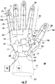
- FIG. 3 is an anterior view of a prosthetic hand device 300 in accordance with an embodiment of the invention.
- the device 300 includes a base 302 and digits comprising fingers 304, a thumb 306, or any other type of flexible or deflectable element.
- the device can include a covering 307, as described above, and that can be composed of one or more elastic portions.
- Each of the digits in prosthetic hand device 300 includes one or more phalangeal portions 308 interconnected by flexible joint portions 310 to allow flexing or deflection of the digits in prosthetic hand device 300.
- An additional flexible joint portion 312 can be used to connect the digits to base 302.
- joints referenced herein refers to any type of external or integrally formed joint device or structure that is operable to provide a connection between two portions of a device and that allows movement with one or more degrees of freedom between them.
- Joint devices and structures can include devices in which movement is provided via a flexible material or moving components.
- joint devices and structures can include any type of hinge device or structure.
- the digits in prosthetic hand device 300 can be actuated using one or more force actuators 314 controlled by a control system 315.
- the control system 315 can be configured to monitor the operation of force actuators 314 in accordance with an actuation force and an amount of displacement, as described above with respect to FIG. 2 .
- the control system can be coupled to one or more EMG signals to provide one or more actuation input to cause motion of the digits in the prosthetic hand device 300.
- the force actuators 314 are connected the distal ends 316 of the digits of prosthetic hand device 300 via one or more actuating structures threaded through the phalangeal portions 308.
- the actuating structures can include a cable portion 318 and a stack portion 320 located in a phalangeal portion 308 associated with a distal end 316 of each of the digits of prosthetic hand device 300. A description of the stack portion 320 will be provided below with respect to FIG. 4 .
- the prosthetic hand device 300 is configured to provide an opposable thumb.
- thumb 306 can be connected to base 302 via an opposable portion 322 connected to base 302 with hinge 324.
- This hinged portion can also be actuated using a force actuator 326 using a actuating structure including a cable portion 328 for apply force to a stack portion 330 in opposing portion.
- the force actuators 314 displace cables 318 (i.e., apply a force to cable 318), causing fingers 304 and thumb 306 to flex according to joints 310.
- force actuator 326 displaces cables 328 (i.e., applies a force to cable 328), causing opposing portion 322 to flex according to hinge 324.
- base 302, phalangeal portions 308, joints 310, opposing portion 322, and hinge 324 can be configured to allow motion in an anterior direction to approximate the motion of digits in a natural hand.
- one or more of the digits of prosthetic hand device 300 can be configured to operate in concert using a single force actuator 314.
- the thumb 306 and index finger 307 are each operated by a separate one of actuators 314 and actuating structures 318.
- the remainder of fingers 304 are configured to operate using actuating structures connected to a single force actuator.
- Such a configuration can generally be provided in prosthetic hand device 300 since independent motion of a thumb or an index finger is most common in gesturing and grasping or contacting of objects.
- This configuration also permits a simpler configuration for control system 315, as the control of only 3 fingers and an opposing thumb motion is effectively required.
- the various embodiments of the invention are not limited in this regard and independent control of all digits in hand 300 can be provided.
- the hand device 300 can be a portion of a larger device, such as a prosthetic arm device.
- the hand device 300 can be mechanically coupled to at least one member 332, as shown in FIG. 3 .
- the member 332 can be configured to attachment to a residual limb or other portion of a user's body.
- the member 332 can include any number of movable joints, including a movable joint at joint 333 between member 332 and hand device 300.
- the member 332 can include a socket 334 for attaching member 332 to a residual limb.
- member 332 can be configured to be attached to a user's body in any other way.
- the member 332 can include sensors 336, such as EMG electrodes.
- the invention is not limited in this regard and the sensors 336 can reside external to the member 332. The configuration of the sensors 336 can be adjusted based on the particular user or source of control signals.
- control of the prosthetic hand device 300 is provided by pre-defining the stiffnesses of the series elastic component and parallel elastic components.
- the series elastic components are provided by the stack portions 320, 330. A more detailed description of these stack portions will now be provided with respect to FIG. 4 .
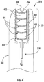
- FIG. 4 shows a partial cutaway view of a section of a phalangeal portion 308 associated with a distal end 316 of one of the digits of prosthetic hand device 300.
- Stack portion 330 is similarly configured, therefore the explanation below is sufficient for describing the operation of stack portion 330.
- stack portion 320 provides the series elastic component by including an annular layered stack of spring disc devices 402 and thin rigid plates 404, 405, 406, with the cable 318 passing through the center of the discs 402 and plates 404, 405, 406.
- the cable 318 can include a stopper or head 408 to attach cable 318 to upper plate 406 or sized larger than the annular opening in plate 406 to prevent cable 318 from being disconnected from stack portion 320.
- the stopper 308 applies force to the plates 404, 405, 406.
- This force compresses discs 402.
- stack portion 320, and particularly plate 405 exerts force against phalangeal portion 308.
- the net effect is to provide an series elastic component between phalangeal portion 308 and a force actuator 314.
- the phalangeal portion 308 provides the element 204
- the plate 405 provides the connection between the element 204 and the series elastic component 214
- the discs 402 provide the series elastic component 214
- the plate 406 provides the connection between the series elastic component 214 and the force actuator 202.
- spring disc devices 402 comprise elastomeric discs operating as compressive spring devices.
- any type of spring device can be used to provide the spring discs, including elastomeric and non-elastomeric spring devices.
- prosthetic hand device 300 can include additional elastic elements to provide the necessary parallel elastic component.
- An exemplary configuration for prosthetic hand device 300 is shown in FIGs. 5A-5C .
- FIGs. 5A-5C show side views of prosthetic hand device 300 in various positions, where prosthetic hand device 300 is configured to include parallel elastic elements in accordance with an embodiment of the invention.
- each of joints 310 includes a joint spring device 502 to provide the parallel elastic component.
- FIGs, 5A-5C show spring devices 502 as torsional spring devices, the invention is not limited in this regard. In the various embodiments of the invention, any type of spring device can be used to provide the joint spring devices.
- the joint spring devices 502 provide increasing restorative force to restore the position of the digits as the digits of prosthetic hand device 300 are flexed or deflected. With respect to FIG. 2 , the restorative force of these joint spring devices provide the parallel elastic component 208, as they apply a force to restore a position of element 204 (i.e., the digits of prosthetic hand device 300).
- FIG. 6 there is provided a detailed block diagram of a computing device 600 which can be implemented as control system 315. Although various components are shown in FIG. 6 , the computing device 600 may include more or less components than those shown in FIG. 6 . However, the components shown are sufficient to disclose an illustrative embodiment of the invention.
- the hardware architecture of FIG. 6 represents only one embodiment of a representative computing device for controlling a jointed mechanical device.
- computing device 600 includes a system interface 622, a Central Processing Unit (CPU) 606, a system bus 610, a memory 612 connected to and accessible by other portions of computing device 600 through system bus 610, and hardware entities 614 connected to system bus 610. At least some of the hardware entities 614 perform actions involving access to and use of memory 612, which may be any type of volatile or non-volatile memory devices.
- memory can include, for example, magnetic, optical, or semiconductor based memory devices.
- the various embodiments of the invention are not limited in this regard.
- computing system can include a user interface 602.
- User interface 610 can be an internal or external component of computing device 600.
- User interface 602 can include input devices, output devices, and software routines configured to allow a user to interact with and control software applications installed on the computing device 600.
- Such input and output devices include, but are not limited to, a display screen 604, a speaker (not shown), a keypad (not shown), a directional pad (not shown), a directional knob (not shown), and a microphone (not shown).
- user interface 602 can facilitate a user-software interaction for launching software development applications and other types of applications installed on the computing device 600.
- System interface 622 allows the computing device 600 to communicate directly or indirectly with the other devices, such as an external user interface or other computing devices.
- computing device can include hardware entities 614, such as microprocessors, application specific integrated circuits (ASICs), and other hardware.
- the hardware entities 614 can also include a removable memory unit 616 comprising a computer-readable storage medium 618 on which is stored one or more sets of instructions 620 (e.g., software code) configured to implement one or more of the methodologies, procedures, or functions described herein.
- the instructions 620 can also reside, completely or at least partially, within the memory 612 and/or within the CPU 606 during execution thereof by the computing device 600.
- the memory 612 and the CPU 606 also can constitute machine-readable media.
- While the computer-readable storage medium 618 is shown in an exemplary embodiment to be a single storage medium, the term “computer-readable storage medium” should be taken to include a single medium or multiple media (e.g., a centralized or distributed database, and/or associated caches and servers) that store the one or more sets of instructions.
- the term “computer-readable storage medium” shall also be taken to include any medium that is capable of storing, encoding or carrying a set of instructions for execution by the machine and that cause the machine to perform any one or more of the methodologies of the present disclosure.
- computer-readable storage medium shall accordingly be taken to include, but not be limited to solid-state memories (such as a memory card or other package that houses one or more read-only (non-volatile) memories, random access memories, or other re-writable (volatile) memories), magneto-optical or optical medium (such as a disk or tape). Accordingly, the disclosure is considered to include any one or more of a computer-readable storage medium or a distribution medium, as listed herein and to include recognized equivalents and successor media, in which the software implementations herein are stored.
- System interface 622 can include a network interface unit configured to facilitate communications over a communications network with one or more external devices. Accordingly, a network interface unit can be provided for use with various communication protocols including the IP protocol.
- Network interface unit can include, but is not limited to, a transceiver, a transceiving device, and a network interface card (NIC).
- NIC network interface card
Landscapes
- Health & Medical Sciences (AREA)
- Transplantation (AREA)
- Orthopedic Medicine & Surgery (AREA)
- Heart & Thoracic Surgery (AREA)
- Engineering & Computer Science (AREA)
- Biomedical Technology (AREA)
- Oral & Maxillofacial Surgery (AREA)
- Vascular Medicine (AREA)
- Life Sciences & Earth Sciences (AREA)
- Animal Behavior & Ethology (AREA)
- General Health & Medical Sciences (AREA)
- Public Health (AREA)
- Veterinary Medicine (AREA)
- Cardiology (AREA)
- Prostheses (AREA)
Description
- The present invention relates to powered mechanical devices, and more specifically to jointed mechanical devices.
- In general, the motion of jointed mechanical devices, such as robotic hand prosthetic devices, can be controlled with control signals and/or sensors monitoring the motors within the jointed mechanical device. However, fine motor control of such devices is typically difficult to achieve, as the amount of feedback sensory information available in natural limbs and appendages greatly exceeds the amount of feedback information typically available in conventional jointed mechanical devices, Although some jointed mechanical devices have been constructed to include additional feedback sensors, the additional costs, complexity, and weight associated with such feedback sensor systems are generally impractical.
- Additionally, the number of signals available for controlling such devices is fairly limited, resulting in only a few types of inputs being available for a relatively large number of components. For example, in some types of robotic prosthetic devices, a measurement of the electric potential generated by the muscles in a residual limb, commonly referred to as an electromyogram (EMG) signal, is used to control the movements of the prosthesis. In such devices, EMG signals can be used to command the forward and/or reverse velocity of one or more electric motors configured to actuate the prosthesis. One common type of robotic prosthetic device using EMG signals is a myoelectric hand and/or arm prosthetic device.
- Hand and/or myoelectric prosthetic devices typically operate based on EMG signals generated by the muscles of the residual forearm or upper arm. However, a residual limb typically only produces a few usable EMG signals. Consequently, even though such prosthetic devices can be designed to be anthropomorphic to provide a visually pleasing prosthesis, the limited number of EMG signals generally results in limited utility. In the case of conventional myoelectric hand prostheses, only a sophisticated claw is generally provided. That is, these prosthetic devices are generally designed to provide a "pinch-type" operation, permitting the user to grasp an object but little else. Although, the ability to grasp and hold objects can be a significant improvement in the lifestyle of a hand and/or arm amputee, the utility of such devices is limited. Although more sophisticated designs are available, the additional costs, complexity, and weight associated with such devices are generally impractical.
-
EP 1 195 151 A1 is considered to represent the closest prior art and discloses a movable finger for prostheses. This device comprises: - at least one element having a fixed end and a detachable end;
- at lest one actuating structure having a first end coupled to the detachable end of said element, wherein the actuating structure comprises at least one elastic element in series with at least one non-elastic element;
- at least one force actuator configured to apply an actuator force to a second end of the actuating structure; and
- Wiste t. et al. "Design of a multifunctional anthropomorphic prosthetic hand with extrinsic actuation" - REHABILITATION ROBOTICS, 2009, ICORR 2009. IEEE International Conference on IEEE, Piscataway, NJ, USA, 23 June 2009, pages 675-681, disclose an anthropomorphic prototype hand prosthesis that is intended for use with a multiple channel myoelectric interface. This document also discloses a method of controlling a jointed mechanical device comprising at least one element having a fixed end and a deflectable end, at least one actuating structure having a first end coupled to the deflectable end of the element, and at least one force actuator configured to apply an actuator force to a second end of the actuating structure, the method comprising:
- monitoring an amplitude of at least one signal associated with at least one actuation input;
- determining an amount of the actuator force applied by the force actuator to the second end of the actuating structure and an amount of displacement generated by the force actuator;
- adjusting an operation of the force actuator based at least on the monitored amplitude, the amount of the actuator force, and the amount of displacement.
- Embodiments of the present invention concern jointed mechanical devices. In a first embodiment of the invention, a device according to claim 1 is provided. The device includes at least one element having a fixed end and a deflectable end. The device also includes at least one actuating structure having a first end coupled to at least said deflectable end of said element, where said actuating structure comprising at least one elastic element in series with at least one non-elastic element. The device further includes at least one force actuator configured to apply an actuator force to a second end of said actuating structure. Additionally, the device includes a control system for adjusting an operation of said force actuator based at least one actuation input, an amount of said actuator force, and an amount of displacement generated by said force actuator. The control system comprises a computing device for detecting when said element is in contact with an object and for operating said force actuator using one of a motion control mode and a force control mode based on said detecting, said detecting based on said amount of said actuator force and said amount of displacement.
- In a second embodiment of the invention, a device according to claim 6 is provided. The device includes a base and at least one digit pivotably coupled to said base, where said digit comprising a plurality of phalangeal portions connected by a plurality of flexible joint portions. The device further includes at least one actuating structure having a first end coupled to a distal end of said digit, where said actuating structure comprising at least one elastic element in series with at least one non-elastic element. The device additionally includes at least one force actuator configured to apply an actuator force to a second end of said actuating structure. The device also includes a control system for adjusting an operation of said force actuator based at least one actuation input, an amount of said actuator force, and an amount of displacement generated by said force actuator. The control system further comprises a computing device for detecting when said digit is in contact with an object and for operating said force actuator according to one of a motion control mode and a force control mode based on said detecting, said detecting based on said amount of said actuator force and said amount of displacement.
- In a third embodiment of the invention, a method according to claim 10 is provided for controlling a jointed mechanical device comprising at least one element having a fixed end and a deflectable end, at least one actuating structure having a first end coupled to at least said deflectable end of said element, and at least one force actuator configured to apply an actuator force to a second end of said actuating structure, where said actuating structure comprises at least one elastic element in series with at least one non-elastic element. The method includes the step of monitoring an amplitude of at least one signal associated with at least one actuation input. The method also includes the step of determining an amount of said actuator force applied by said force actuator to said second end of said actuating structure and an amount of displacement generated by said force actuator. The method further includes the step of adjusting an operation of said force actuator based at least one said monitored amplitude, said amount of said actuator force, and said amount of displacement. Said adjusting further comprises detecting when said element is in contact with an object based on said amount of said actuator force and said amount of displacement and operating said force actuator using one of a motion control mode and a force control mode based on said detecting.
- In a fourth embodiment of the invention, a prosthetic device according to claim 13 is provided. The prosthetic device includes at least one member and a hand device according to claim 6 coupled to the member.
-
-
FIG. 1A-1C are diagrams showing grasping of a ball by a hand that is useful for understanding the various embodiments of the invention. -
FIG. 2 shows a schematic diagram of anactuation system 200 for a prosthetic hand device in accordance with an embodiment of the invention. -
FIG. 3 is an anterior view of aprosthetic hand device 300 in accordance with an embodiment of the invention. -
FIG. 4 shows a partial cutaway view of a section of a phalangeal portion associated with a distal end of one of the digits of prosthetic hand device inFIG. 3 . -
FIGs. 5A-5C show side views of the prosthetic hand device ofFIG. 3 in various positions, illustrating one configuration for parallel elastic elements in accordance with an embodiment of the invention. -
FIG. 6 is block diagram of a computing device which can be implemented as control system in accordance with an embodiment of the invention. - The present invention is described with reference to the attached figures, wherein like reference numerals are used throughout the figures to designate similar or equivalent elements. The figures are not drawn to scale and they are provided merely to illustrate the instant invention. Several aspects of the invention are described below with reference to example applications for illustration. It should be understood that numerous specific details, relationships, and methods are set forth to provide a full understanding of the invention. One having ordinary skill in the relevant art, however, will readily recognize that the invention can be practiced without one or more of the specific details or with other methods. In other instances, well-known structures or operations are not shown in detail to avoid obscuring the invention. The present invention is not limited by the illustrated ordering of acts or events, as some acts may occur in different orders and/or concurrently with other acts or events. Furthermore, not all illustrated acts or events are required to implement a methodology in accordance with the present invention.
- Although overall motion control of the hand or other appendage is important during gesturing, control of force is generally desirable during grasping. That is, a hand may apply different amount of forces before and after grasping or contacting an object. In general, a greater amount of force may be applied to move fingers quickly into place for grasping or contacting an object. Afterwards, the brain, based on feedback obtained from nerves in the arm and hand, automatically adjusts the amount force applied by the finger depending on the shape, size, and type of object. Such fine motor control is typically unachievable in jointed mechanical devices, as a large amount of sensory information is needed in conjunction with the ability to tune the amount of force being applied. The term "jointed mechanical device" as used herein, refers to any powered mechanical device having one or more movable joints, including, but not limited to, robotic prosthetic and robotic non-prosthetic devices. As described above, jointed mechanical devices can be configured to include a large number of sensors, but the additional costs, complexity, and weight associated with such feedback sensor systems are generally impractical. Additionally, the number of inputs available is typically limited. As a result, a user of such a device, such as a myoelectric prosthesis, can generally only provide an up/down signal for a particular direction or axis of motion. This configuration enables position control, but does not generally provide any type of force control.
- To overcome the limitations of existing jointed mechanical devices, embodiments of the invention provide systems and methods for providing some amount of fine motor control in such devices designed for grasping or contacting an object. In particular, the various embodiments of the invention provide a jointed mechanical device that automatically switches between a motion control mode when the device is operating in free space and force control mode when the device grasps or contacts an object. This is conceptually illustrated in
FIGs. 1A-1C . -
FIG. 1A shows a diagram of ahand 100 about to grasp or contact an object, in this case aball 102. In this pre-grasp or pre-contact stage, the digits ofhand 100, such asindex finger 104 andthumb 106 are positioned to approachball 102. In general, this placement can occur very quickly and all motion inhand 100 is directed to the placement of these digits. Accordingly, in a robotic or prosthetic hand device, a motion control mode can be used during the pre-contact period to move the digits in such a device as quickly as possible to a contact point. However, the digit velocities during such a pre-contact period can result in an undesirable amount of force after contact. - As illustrated in
FIG. 1B ,finger 104 andthumb 106 may come into contact withball 102 at some point in time. As described above, the difficulty in most jointed mechanical devices is how to proceed from this point of contact without sophisticated sensory information. If the same force or rate of change in digit position used while approachingball 102 is applied once contact has been made withball 102, the resulting force may be too high, possibly damaging or distortingball 102. Such distortion is shown inFIG. 1C , where the additional and continuing force crushes portions ofball 102. - In a natural hand, force is automatically adjusted by the brain based on sensory inputs. In a simplest sense, motion of the
index finger 104 andthumb 106 is effectively halted or slowed to permit grasping ofball 102 without the need to crushball 102. Therefore, the various embodiments of the invention provide a jointed mechanical device and associated control system, such that the point of contact with and object is detected, the operation of the device is subsequently changed to a force control mode such that events, such as crushing of the object, do not necessarily occur. For example, in a myoelectric prosthesis, the change in digit position (i.e., the force applied) in response to an EMG signal is altered. In particular, the force control mode can provide for a slower change in digit position as opposed to the change in digit position prior to contact during a motion control mode. Accordingly, the user is provided with a means of utilizing the typically limited number of myoelectric signals to control both gross and fine motor control. In particular, embodiments of the invention not only operate a jointed mechanical device in first mode prior to contact and a second mode subsequent to contact, but can detect the point of contact to trigger the change in mode. - In particular, the modes of operation in the various embodiments of the invention can be triggered without explicitly requiring force sensors or direct force control of the actuator. In particular, a structure and associated control system are provided that enable multiple modes from an otherwise dedicated motion controlled actuator. As a result, only limited sensing and electronic motion control is required for controlling operation of a jointed mechanical device, such as a robotic prosthetic device.
- Although the various embodiments of the invention will be described with respect to a prosthetic hand device, this is for illustrative purposes only. One of ordinary skill in the art will recognize that the various embodiments of the invention can be applied to any type of jointed mechanical device configured for grasping, contacting, or holding objects. Furthermore, although only two modes of operation will be described below for the exemplary prosthetic hand device, the various embodiments of the invention are not limited in this regard. One of ordinary skill in the art will recognize that more than two modes of operation are possible, depending on the configuration of the device.
-
FIG. 2 shows a schematic diagram of anactuation system 200 for a prosthetic hand device in accordance with an embodiment of the invention. As shown inFIG. 2 , thesystem 200 includes a position-controlledforce actuator 202 that causes motion of a digit or other deflectable ormovable element 204 connected to actuator 202 by anactuating structure 206. In operation, as the position of theactuator 202 is changed, force is applied to actuatingstructure 206, resulting in the motion ofelement 204. In some embodiments, thesystem 200 can also include a parallel spring orrestorative element 208 betweenelement 204 and afixed point 210. Therestorative element 208 is configured to counter the force applied to actuatingstructure 206 to effectively provide a parallel spring force defined by a stiffness (i.e., spring constant) Kp. - In some embodiments of the invention, the
force actuator 202 can comprise an electric motor and pulley assembly configured to operate with a cable of theactuating structure 206. Additionally, such a configuration can also include a roller clutch between a motor and a pulley in theforce actuator 202. The roller clutch can be used to lock a cable of the actuating structure in place, thus theelement 204 is also locked at a position when the motor is turned off. - As described above, automatic switching between a motion control mode and a force control mode is provided in the various embodiments of the invention when an element comes into contact with an object. Referring back to
FIG. 2 , this switching should occur whenelement 204 comes into contact withrigid object 212. Such automatic control can be achieved by including inactuating structure 206 at least oneelastic component 214 betweenelement 204 andactuator 202. The placement of theelastic component 214 betweenelement 204 andactuator 202 effectively provides a spring force in series withcomponents - If the parallel (restorative) stiffness kp and the serial stiffness ks are known, a control methodology for switching between a motion control mode and a force control mode can be developed. For example, assuming the series stiffness and parallel stiffness are approximately the same order (ks ≈ kp) and
element 204 is not in contact with arigid object 212, the amount of displacement x of theelement 204 from a resting position will be in proportion to the amount of displacement provided by the force actuator, as shown below in Equation (1):
element 204 is not in contact with a rigid object, the relationship between actuator force and actuator displacement can be given by Equation (2):
element 204 has come into contact withrigid object 212. In embodiments of the invention utilizing electric motors, the actuator force and the actuator displacement can monitored by measuring, for example, an input current to the electric motor and an amount of rotation of the electric motor. - In particular, once the relationship in Equation (2) no longer holds true, this indicates that
element 204 has come into contact withobject 212. When this condition is detected, displacement provided by theactuator 202 needs to be controlled according to a force control mode. Once in contact with the object, the relationship between the amount of force provided by the force actuator and the amount of actuator displacement changes to:
element 204 is not contactingrigid object 212. That is, once the relationship in Equation (3) no longer holds true, this indicates thatelement 204 is no longer in contact withobject 212. - Although the embodiment above has been described with respect to monitoring compliance with Equation (2) or Equation (3), the various embodiments of the invention are not limited in this regard. For example, in some embodiments of the invention, both Equation (2) and Equation (3) can be continually evaluated and a decision of whether of operate in a motion control mode or a force control mode can be made on the basis of which equation is being substantially met.
- By using the control methodology described above, the motion of the prosthesis can be controlled in a motion control mode when gesturing, and in a force control mode when grasping or contacting an object. Furthermore, if a roller clutch is used to "lock in" a given motor position, the clutch will provide the dual function of locking the position of the prosthesis when gesturing or locking in the force being applied to an object when grasping.
- Note that Equation (3) does not depend on the stiffness of the object. However, the detection of contact with the object, based on Equation (2), relies on the assumption that the object is stiff relative to kp. If the object is compliant relative to kp (e.g., a sponge or other object having a stiffness kobject < kp ), the switch to a force control mode will be delayed. In general, force control is not as important in such cases, since either position or force control work equally well when grasping highly compliant objects.
- In some embodiments of the invention, a robotic hand will likely have a covering comprising an elastomer and/or one or more other elastic materials to emulate the appearance of a natural hand. This covering will constitute a portion of the parallel stiffness in the robotic hand, and corresponding information regarding the covering can be provided to a controller to allow more accurate detection of contact with an object using Equation (2). In such embodiments, the stiffness of the covering and/or any other stiffnesses present in the robotic hand can be automatically mapped and/or detected in a calibration routine. During such a routine, the robotic hand can be commanded to slowly close and open while not grasping an object, while a controller monitors the motor position and current. The controller can then create a position/force map that represents the hand behavior in the absence of an object and use this map during normal operation of the robotic hand.
- An exemplary prosthetic hand device for use with the methodology described above in shown in
FIGs. 3-5 .FIG. 3 is an anterior view of aprosthetic hand device 300 in accordance with an embodiment of the invention. As shown inFIG. 3 , thedevice 300 includes abase 302 anddigits comprising fingers 304, athumb 306, or any other type of flexible or deflectable element. Optionally, the device can include a covering 307, as described above, and that can be composed of one or more elastic portions. Each of the digits inprosthetic hand device 300 includes one or morephalangeal portions 308 interconnected by flexiblejoint portions 310 to allow flexing or deflection of the digits inprosthetic hand device 300. An additional flexiblejoint portion 312 can be used to connect the digits tobase 302. - In the various embodiments of the invention, the joints referenced herein refers to any type of external or integrally formed joint device or structure that is operable to provide a connection between two portions of a device and that allows movement with one or more degrees of freedom between them. Joint devices and structures can include devices in which movement is provided via a flexible material or moving components. For example, joint devices and structures can include any type of hinge device or structure.
- The digits in
prosthetic hand device 300 can be actuated using one ormore force actuators 314 controlled by acontrol system 315. As described above, thecontrol system 315 can be configured to monitor the operation offorce actuators 314 in accordance with an actuation force and an amount of displacement, as described above with respect toFIG. 2 . Additionally, the control system can be coupled to one or more EMG signals to provide one or more actuation input to cause motion of the digits in theprosthetic hand device 300. - The
force actuators 314 are connected the distal ends 316 of the digits ofprosthetic hand device 300 via one or more actuating structures threaded through thephalangeal portions 308. The actuating structures can include acable portion 318 and astack portion 320 located in aphalangeal portion 308 associated with adistal end 316 of each of the digits ofprosthetic hand device 300. A description of thestack portion 320 will be provided below with respect toFIG. 4 . - In the embodiment shown in
FIG. 3 , theprosthetic hand device 300 is configured to provide an opposable thumb. In particular,thumb 306 can be connected to base 302 via anopposable portion 322 connected to base 302 withhinge 324. This hinged portion can also be actuated using aforce actuator 326 using a actuating structure including acable portion 328 for apply force to astack portion 330 in opposing portion. - In operation, the
force actuators 314 displace cables 318 (i.e., apply a force to cable 318), causingfingers 304 andthumb 306 to flex according tojoints 310. Similarly,force actuator 326 displaces cables 328 (i.e., applies a force to cable 328), causing opposingportion 322 to flex according tohinge 324. Although the digits ofprosthetic hand device 300 and opposingportion 322 could potentially flex in any direction, one of ordinary skill in the art would recognize thatbase 302,phalangeal portions 308,joints 310, opposingportion 322, and hinge 324 can be configured to allow motion in an anterior direction to approximate the motion of digits in a natural hand. - In the embodiment shown in
FIG. 3 , one or more of the digits ofprosthetic hand device 300 can be configured to operate in concert using asingle force actuator 314. For example, as shown inFIG. 3 , thethumb 306 andindex finger 307 are each operated by a separate one ofactuators 314 and actuatingstructures 318. However, the remainder offingers 304 are configured to operate using actuating structures connected to a single force actuator. Such a configuration can generally be provided inprosthetic hand device 300 since independent motion of a thumb or an index finger is most common in gesturing and grasping or contacting of objects. This configuration also permits a simpler configuration forcontrol system 315, as the control of only 3 fingers and an opposing thumb motion is effectively required. However, the various embodiments of the invention are not limited in this regard and independent control of all digits inhand 300 can be provided. - In some embodiments of the invention, the
hand device 300 can be a portion of a larger device, such as a prosthetic arm device. In such embodiments, thehand device 300 can be mechanically coupled to at least onemember 332, as shown inFIG. 3 . Themember 332 can be configured to attachment to a residual limb or other portion of a user's body. Themember 332 can include any number of movable joints, including a movable joint at joint 333 betweenmember 332 andhand device 300. For example, as shown inFIG. 3 , themember 332 can include asocket 334 for attachingmember 332 to a residual limb. However, the various embodiments of the invention are not limited in this regard andmember 332 can be configured to be attached to a user's body in any other way. In some embodiments, themember 332 can includesensors 336, such as EMG electrodes. However, the invention is not limited in this regard and thesensors 336 can reside external to themember 332. The configuration of thesensors 336 can be adjusted based on the particular user or source of control signals. - As described above, control of the
prosthetic hand device 300 is provided by pre-defining the stiffnesses of the series elastic component and parallel elastic components. Inprosthetic hand device 300, the series elastic components are provided by thestack portions FIG. 4 . -
FIG. 4 shows a partial cutaway view of a section of aphalangeal portion 308 associated with adistal end 316 of one of the digits ofprosthetic hand device 300.Stack portion 330 is similarly configured, therefore the explanation below is sufficient for describing the operation ofstack portion 330. - As shown in
FIG. 4 ,stack portion 320 provides the series elastic component by including an annular layered stack ofspring disc devices 402 and thinrigid plates cable 318 passing through the center of thediscs 402 andplates cable 318 can include a stopper orhead 408 to attachcable 318 toupper plate 406 or sized larger than the annular opening inplate 406 to preventcable 318 from being disconnected fromstack portion 320. - In operation, when a force F is applied to
cable 318, thestopper 308 applies force to theplates discs 402. As a result of this compression,stack portion 320, and particularlyplate 405, exerts force againstphalangeal portion 308. The net effect is to provide an series elastic component betweenphalangeal portion 308 and aforce actuator 314. With reference toFIG. 2 , thephalangeal portion 308 provides theelement 204, theplate 405 provides the connection between theelement 204 and the serieselastic component 214, thediscs 402 provide the serieselastic component 214, and theplate 406 provides the connection between the serieselastic component 214 and theforce actuator 202. In the embodiment inFIG. 4 ,spring disc devices 402 comprise elastomeric discs operating as compressive spring devices. However, in the various embodiments of the invention, any type of spring device can be used to provide the spring discs, including elastomeric and non-elastomeric spring devices. - Although the
discs 402 inFIG. 4 provide a restorative force for the digits inprosthetic hand device 300, thus providing a component of the parallel stiffness, in general this does not provide a parallel stiffness on the order of the series stiffness. As a result, the restorative force provided by the decompression force of thediscs 402 may be insufficient to restoreprosthetic hand device 300 to a previous or resting position. Accordingly, in some embodiments of the invention,prosthetic hand device 300 can include additional elastic elements to provide the necessary parallel elastic component. An exemplary configuration forprosthetic hand device 300 is shown inFIGs. 5A-5C . -
FIGs. 5A-5C show side views ofprosthetic hand device 300 in various positions, whereprosthetic hand device 300 is configured to include parallel elastic elements in accordance with an embodiment of the invention. Inprosthetic hand device 300, each ofjoints 310 includes ajoint spring device 502 to provide the parallel elastic component. AlthoughFIGs, 5A-5C show spring devices 502 as torsional spring devices, the invention is not limited in this regard. In the various embodiments of the invention, any type of spring device can be used to provide the joint spring devices. In operation, as shown inFIGs. 5B and 5C , thejoint spring devices 502 provide increasing restorative force to restore the position of the digits as the digits ofprosthetic hand device 300 are flexed or deflected. With respect toFIG. 2 , the restorative force of these joint spring devices provide the parallelelastic component 208, as they apply a force to restore a position of element 204 (i.e., the digits of prosthetic hand device 300). - Referring now to
FIG. 6 , there is provided a detailed block diagram of acomputing device 600 which can be implemented ascontrol system 315. Although various components are shown inFIG. 6 , thecomputing device 600 may include more or less components than those shown inFIG. 6 . However, the components shown are sufficient to disclose an illustrative embodiment of the invention. The hardware architecture ofFIG. 6 represents only one embodiment of a representative computing device for controlling a jointed mechanical device. - As shown in
FIG. 6 ,computing device 600 includes asystem interface 622, a Central Processing Unit (CPU) 606, a system bus 610, a memory 612 connected to and accessible by other portions ofcomputing device 600 through system bus 610, andhardware entities 614 connected to system bus 610. At least some of thehardware entities 614 perform actions involving access to and use of memory 612, which may be any type of volatile or non-volatile memory devices. Such memory can include, for example, magnetic, optical, or semiconductor based memory devices. However the various embodiments of the invention are not limited in this regard. - In some embodiments, computing system can include a user interface 602. User interface 610 can be an internal or external component of
computing device 600. User interface 602 can include input devices, output devices, and software routines configured to allow a user to interact with and control software applications installed on thecomputing device 600. Such input and output devices include, but are not limited to, adisplay screen 604, a speaker (not shown), a keypad (not shown), a directional pad (not shown), a directional knob (not shown), and a microphone (not shown). As such, user interface 602 can facilitate a user-software interaction for launching software development applications and other types of applications installed on thecomputing device 600. -
System interface 622 allows thecomputing device 600 to communicate directly or indirectly with the other devices, such as an external user interface or other computing devices. Additionally, computing device can includehardware entities 614, such as microprocessors, application specific integrated circuits (ASICs), and other hardware. As shown inFIG. 6 , thehardware entities 614 can also include aremovable memory unit 616 comprising a computer-readable storage medium 618 on which is stored one or more sets of instructions 620 (e.g., software code) configured to implement one or more of the methodologies, procedures, or functions described herein. Theinstructions 620 can also reside, completely or at least partially, within the memory 612 and/or within theCPU 606 during execution thereof by thecomputing device 600. The memory 612 and theCPU 606 also can constitute machine-readable media. - While the computer-
readable storage medium 618 is shown in an exemplary embodiment to be a single storage medium, the term "computer-readable storage medium" should be taken to include a single medium or multiple media (e.g., a centralized or distributed database, and/or associated caches and servers) that store the one or more sets of instructions. The term "computer-readable storage medium" shall also be taken to include any medium that is capable of storing, encoding or carrying a set of instructions for execution by the machine and that cause the machine to perform any one or more of the methodologies of the present disclosure. - The term "computer-readable storage medium" shall accordingly be taken to include, but not be limited to solid-state memories (such as a memory card or other package that houses one or more read-only (non-volatile) memories, random access memories, or other re-writable (volatile) memories), magneto-optical or optical medium (such as a disk or tape). Accordingly, the disclosure is considered to include any one or more of a computer-readable storage medium or a distribution medium, as listed herein and to include recognized equivalents and successor media, in which the software implementations herein are stored.
-
System interface 622 can include a network interface unit configured to facilitate communications over a communications network with one or more external devices. Accordingly, a network interface unit can be provided for use with various communication protocols including the IP protocol. Network interface unit can include, but is not limited to, a transceiver, a transceiving device, and a network interface card (NIC). - Applicants present certain theoretical aspects above that are believed to be accurate that appear to explain observations made regarding embodiments of the invention. However, embodiments of the invention may be practiced without the theoretical aspects presented. Moreover, the theoretical aspects are presented with the understanding that Applicants do not seek to be bound by the theory presented.
- While various embodiments of the present invention have been described above, it should be understood that they have been presented by way of example only, and not limitation. Numerous changes to the disclosed embodiments can be made in accordance with the disclosure herein without departing from the scope of the invention. Thus, the breadth and scope of the present invention should not be limited by any of the above described embodiments. Rather, the scope of the invention should be defined in accordance with the following claims.
- Although the invention has been illustrated and described with respect to one or more implementations, equivalent alterations and modifications will occur to others skilled in the art upon the reading and understanding of this specification and the annexed drawings. In addition, while a particular feature of the invention may have been disclosed with respect to only one of several implementations, such feature may be combined with one or more other features of the other implementations as may be desired and advantageous for any given or particular application.
- The terminology used herein is for the purpose of describing particular embodiments only and is not intended to be limiting of the invention. As used herein, the singular forms "a", "an" and "the" are intended to include the plural forms as well, unless the context clearly indicates otherwise. Furthermore, to the extent that the terms "including", "includes", "having", "has", "with", or variants thereof are used in either the detailed description and/or the claims, such terms are intended to be inclusive in a manner similar to the term "comprising."
- Unless otherwise defined, all terms (including technical and scientific terms) used herein have the same meaning as commonly understood by one of ordinary skill in the art to which this invention belongs. It will be further understood that terms, such as those defined in commonly used dictionaries, should be interpreted as having a meaning that is consistent with their meaning in the context of the relevant art and will not be interpreted in an idealized or overly format sense unless expressly so defined herein.
Claims (13)
- A device, comprising:at least one element (204) having a fixed end and a deflectable end;at least one actuating structure (206) having a first end coupled to at least said deflectable end of said element, said actuating structure comprising at least one elastic element (214) in series with at least one non-elastic element;at least one force actuator (202) configured to apply an actuator force to a second end of said actuating structure; anda control system (315) for adjusting an operation of said force actuator (202) based at least one actuation input, an amount of said actuator force, and an amount of displacement generated by said force actuator (202), the control system comprises a computing device for detecting when said element (204) is in contact with an object and for operating said force actuator (202) using one of a motion control mode and a force control mode based on said detecting, said detecting based on said amount of said actuator force and said amount of displacement.
- The device of claim 1, wherein said non-elastic element comprises at least one cable, wherein said force actuator (202) comprises an electric motor and a pulley for actuating said cable, and wherein said force actuator (202) further comprises a roller clutch between said electric motor and said pulley.
- The device of claim 1, wherein said non-elastic element comprises at least one cable, wherein said force actuator comprises an electric motor and a pulley for actuating said cable, and wherein said control system (315) is configured for adjusting a velocity of said electric motor based on an amplitude of said actuation input.
- The device of claim 1, wherein said non-elastic element comprises at least one cable, wherein said force actuator (202) comprises an electric motor and a pulley for actuating said cable, and wherein said control system (315) is configured for determining said amount of actuator force based on an input current of said electric motor.
- The device of claim 1, wherein said non-elastic element comprises at least one cable, wherein said force actuator (202) comprises an electric motor and a pulley for actuating said cable, and wherein said control system (315) is configured for determining said amount of displacement based on a position measurement of said electric motor.
- A device (300), comprising:a base (302);at least one digit pivotably coupled to said base, said digit comprising a plurality of phalangeal portions (308) connected by a plurality of flexible joint portions (310);at least one actuating structure (318) having a first end coupled to a distal end of said digit, said actuating structure comprising at least one elastic element in series with at least one non-elastic element;at least one force actuator (314) configured to apply an actuator force to a second end of said actuating structure (318); anda control system (315) for adjusting an operation of said force actuator (314) based at least one actuation input, an amount of said actuator force, and an amount of displacement generated by said force actuator (314),wherein said control system (315) further comprises a computing device for detecting when said digit is in contact with an object and for operating said force actuator according to one of a motion control mode and a force control mode based on said detecting, said detecting based on said amount of said actuator force and said amount of displacement.
- The device of claim 6, where each of said flexible joint portions (310) further comprises at least one restorative element for applying a restoring force opposing said actuator force.
- The device of claim 6, wherein said non-elastic element comprises at least one cable, and wherein said force actuator comprises an electric motor and a pulley for actuating said cable.
- The device of claim 6, further comprising at least one sensor (336) for generating said actuation input.
- A method of controlling a jointed mechanical device comprising at least one element (204) having a fixed end and a deflectable end, at least one actuating structure (206) having a first end coupled to at least said deflectable end of said element, and at least one force actuator (202) configured to apply an actuator force to a second end of said actuating structure (206), where said actuating structure comprises at least one elastic element (214) in series with at least one non-elastic element, the method comprising:monitoring an amplitude of at least one signal associated with at least one actuation input;determining an amount of said actuator force applied by said force actuator (202) to said second end of said actuating structure (206) and an amount of displacement generated by said force actuator;adjusting an operation of said force actuator (202) based at least one said monitored amplitude, said amount of said actuator force, and said amount of displacement,wherein said adjusting further comprises detecting when said element is in contact with an object based on said amount of said actuator force and said amount of displacement; and operating said force actuator (202) using one of a motion control mode and a force control mode based on said detecting.
- The method of claim 10, wherein said force actuator (202) comprises an electric motor, wherein said adjusting further comprises adjusting a velocity of said electric motor based on said monitored amplitude, wherein said determining said amount of actuator force is based on an input current of said electric motor, and wherein said determining said amount of displacement is based on a position measurement of said electric motor.
- The method of claim 10, wherein said signal comprises an electromyogram signal.
- A device according to claim 6, which is a hand device (300) and which further comprises at least one member (332) coupled thereto, thus forming a prosthetic device.
Applications Claiming Priority (2)
| Application Number | Priority Date | Filing Date | Title |
|---|---|---|---|
| US23542109P | 2009-08-20 | 2009-08-20 | |
| PCT/US2010/046050 WO2011022569A1 (en) | 2009-08-20 | 2010-08-20 | Jointed mechanical devices |
Publications (2)
| Publication Number | Publication Date |
|---|---|
| EP2467102A1 EP2467102A1 (en) | 2012-06-27 |
| EP2467102B1 true EP2467102B1 (en) | 2017-03-01 |
Family
ID=43037907
Family Applications (1)
| Application Number | Title | Priority Date | Filing Date |
|---|---|---|---|
| EP10748178.0A Not-in-force EP2467102B1 (en) | 2009-08-20 | 2010-08-20 | Jointed mechanical devices |
Country Status (3)
| Country | Link |
|---|---|
| US (3) | US9265625B2 (en) |
| EP (1) | EP2467102B1 (en) |
| WO (1) | WO2011022569A1 (en) |
Families Citing this family (47)
| Publication number | Priority date | Publication date | Assignee | Title |
|---|---|---|---|---|
| GB0910920D0 (en) | 2009-06-24 | 2009-08-05 | Touch Emas Ltd | Method of controlling a prosthesis |
| EP2467102B1 (en) | 2009-08-20 | 2017-03-01 | Vanderbilt University | Jointed mechanical devices |
| WO2011022572A1 (en) | 2009-08-20 | 2011-02-24 | Vanderbilt University | Control system for jointed mechanical devices |
| GB201114264D0 (en) | 2011-08-18 | 2011-10-05 | Touch Emas Ltd | Improvements in or relating to prosthetics and orthotics |
| US20150148728A1 (en) * | 2011-09-08 | 2015-05-28 | Children's Medical Center Corporation | Isolated orthosis for thumb actuation |
| GB201116060D0 (en) | 2011-09-16 | 2011-11-02 | Touch Emas Ltd | Method of controlling a prosthesis |
| GB201116069D0 (en) | 2011-09-16 | 2011-11-02 | Touch Emas Ltd | Method and apparatus for controlling a prosthetic device |
| GB201213030D0 (en) | 2012-07-23 | 2012-09-05 | Touch Emas Ltd | Improvements in or relating to prosthetics and orthotics |
| US10028878B1 (en) * | 2012-11-28 | 2018-07-24 | Vecna Technologies, Inc. | Body worn apparatus |
| GB201302025D0 (en) | 2013-02-05 | 2013-03-20 | Touch Emas Ltd | Improvements in or relating to prosthetics |
| US20150112448A1 (en) * | 2013-10-23 | 2015-04-23 | Kurt W. Scott | Hybrid Prosthetic Hand |
| US10034780B2 (en) | 2014-02-04 | 2018-07-31 | Rehabilitation Institute Of Chicago | Modular and lightweight myoelectric prosthesis components and related methods |
| GB201403265D0 (en) | 2014-02-25 | 2014-04-09 | Touch Emas Ltd | Prosthetic digit for use with touchscreen devices |
| GB201408253D0 (en) | 2014-05-09 | 2014-06-25 | Touch Emas Ltd | Systems and methods for controlling a prosthetic hand |
| GB201417541D0 (en) | 2014-10-03 | 2014-11-19 | Touch Bionics Ltd | Wrist device for a prosthetic limb |
| TWI549666B (en) * | 2015-01-05 | 2016-09-21 | 國立清華大學 | Rehabilitation system with stiffness measurement |
| GB2560420B (en) | 2015-04-30 | 2019-04-24 | Hy5Pro As | Palm unit for artificial hand |
| GB2537899B (en) * | 2015-04-30 | 2018-02-21 | Hy5Pro As | Control of digits for artificial hand |
| CA2934405A1 (en) | 2015-06-26 | 2016-12-26 | Nikolai Dechev | Custom fitted body powered prosthetic upper limb manufactured by 3d printing |
| US10758379B2 (en) * | 2016-05-25 | 2020-09-01 | Scott MANDELBAUM | Systems and methods for fine motor control of fingers on a prosthetic hand to emulate a natural stroke |
| CN105943207B (en) * | 2016-06-24 | 2017-12-05 | 吉林大学 | One kind is based on idiodynamic intelligent artificial limb kinematic system and its control method |
| US11185426B2 (en) | 2016-09-02 | 2021-11-30 | Touch Bionics Limited | Systems and methods for prosthetic wrist rotation |
| WO2018042215A1 (en) | 2016-09-02 | 2018-03-08 | Touch Bionics Limited | Systems and methods for prosthetic wrist rotation |
| CH712952A1 (en) * | 2016-09-26 | 2018-03-29 | Appsocial Org Stiftung | Power-operated prosthesis. |
| CN107378944B (en) * | 2017-06-20 | 2020-12-25 | 东南大学 | Multidimensional surface electromyographic signal artificial hand control method based on principal component analysis method |
| US11311393B2 (en) | 2017-08-06 | 2022-04-26 | Dbm, Llc | Universal digit |
| US10973660B2 (en) | 2017-12-15 | 2021-04-13 | Touch Bionics Limited | Powered prosthetic thumb |
| CA3087674C (en) * | 2018-01-09 | 2023-03-14 | Unlimited Tomorrow, Inc. | Prosthetic arm with adaptive grip |
| IT201800005213A1 (en) * | 2018-05-09 | 2019-11-09 | UNDERACTED PROSTHETIC HAND | |
| US11547581B2 (en) | 2018-12-20 | 2023-01-10 | Touch Bionics Limited | Energy conservation of a motor-driven digit |
| JP6713562B2 (en) * | 2019-02-06 | 2020-06-24 | 社会福祉法人兵庫県社会福祉事業団 | Movable prosthetic hand |
| EP3952794B1 (en) | 2019-04-10 | 2024-05-22 | Touch Bionics Limited | Prosthetic digit with articulating links |
| US11364131B2 (en) | 2019-08-16 | 2022-06-21 | Unlimited Tomorrow, Inc. | Socket for upper extremity prosthesis |
| US11564815B2 (en) | 2019-09-17 | 2023-01-31 | Victoria Hand Project | Upper arm prosthetic apparatus and systems |
| CN114555014B (en) | 2019-09-18 | 2026-02-27 | 塔驰仿生有限公司 | Prosthetic finger and actuator |
| WO2021071915A1 (en) | 2019-10-08 | 2021-04-15 | Unlimited Tomorrow, Inc. | Biometric sensor array |
| US11931270B2 (en) | 2019-11-15 | 2024-03-19 | Touch Bionics Limited | Prosthetic digit actuator |
| CN113545896B (en) * | 2020-04-26 | 2024-06-18 | 京东科技信息技术有限公司 | Bionic hand control method, device, electronic device and computer readable medium |
| US11957606B2 (en) | 2020-10-29 | 2024-04-16 | Victoria Hand Project | Low-cost prosthetic apparatus, methods, kits, and systems with improved force transfer elements |
| US12115087B2 (en) | 2020-11-03 | 2024-10-15 | Touch Bionics Limited | Sensor for prosthetic control |
| US11865017B2 (en) * | 2020-12-18 | 2024-01-09 | Korea Advanced Institute Of Science And Technology | Finger motion assist apparatus |
| US11679011B2 (en) * | 2021-04-30 | 2023-06-20 | Arnex Innovations, Llc | Prosthetic coupling interfaces and methods of use |
| US20230102500A1 (en) * | 2021-09-25 | 2023-03-30 | Tatum Robotics Llc | Technique for actuating a robotic apparatus |
| TR2022002849A1 (en) * | 2022-02-28 | 2023-09-21 | Oezyegin Ueniversitesi | A CONTROLLABLE ARTIFICIAL HAND SYSTEM |
| US20230380992A1 (en) * | 2022-05-24 | 2023-11-30 | Paeon, Inc. | Prosthetic Limb Systems and Devices |
| US20250128403A1 (en) * | 2023-10-20 | 2025-04-24 | Pramana Inc. | Apparatus and method of use of a mechanism that converts rotary motion into linear motion |
| WO2025248439A1 (en) | 2024-05-29 | 2025-12-04 | Fondazione Istituto Italiano Di Tecnologia | Robotic joint |
Family Cites Families (13)
| Publication number | Priority date | Publication date | Assignee | Title |
|---|---|---|---|---|
| US5383939A (en) | 1991-12-05 | 1995-01-24 | James; Kelvin B. | System for controlling artificial knee joint action in an above knee prosthesis |
| US5650704A (en) * | 1995-06-29 | 1997-07-22 | Massachusetts Institute Of Technology | Elastic actuator for precise force control |
| DE60010789T2 (en) | 1999-03-22 | 2004-10-07 | Advanced Control Res Ltd | limbs prostheses |
| JP3086452B1 (en) * | 1999-05-19 | 2000-09-11 | 原田電子工業株式会社 | Movable finger for artificial limb, artificial hand using the movable finger, and control device for the movable finger |
| DE60131377T2 (en) | 2000-03-29 | 2008-09-04 | Massachusetts Institute Of Technology, Cambridge | SPEED ADAPTED AND PATIENT ATTACHED KNEE PROSTHESIS |
| JP3731118B2 (en) | 2002-02-18 | 2006-01-05 | 独立行政法人科学技術振興機構 | Biped walking humanoid robot |
| US7736394B2 (en) * | 2002-08-22 | 2010-06-15 | Victhom Human Bionics Inc. | Actuated prosthesis for amputees |
| WO2004017872A1 (en) | 2002-08-22 | 2004-03-04 | Victhom Human Bionics Inc. | Actuated leg prosthesis for above-knee amputees |
| US8512415B2 (en) * | 2005-03-31 | 2013-08-20 | Massachusetts Institute Of Technology | Powered ankle-foot prothesis |
| US20070123997A1 (en) | 2005-03-31 | 2007-05-31 | Massachusetts Institute Of Technology | Exoskeletons for running and walking |
| JP4908020B2 (en) | 2006-03-02 | 2012-04-04 | 本田技研工業株式会社 | Hand control system |
| WO2008098072A2 (en) | 2007-02-06 | 2008-08-14 | Hanger Orthopedic Group Inc. | System and method for using a digit to position a prosthetic or orthotic device |
| EP2467102B1 (en) | 2009-08-20 | 2017-03-01 | Vanderbilt University | Jointed mechanical devices |
-
2010
- 2010-08-20 EP EP10748178.0A patent/EP2467102B1/en not_active Not-in-force
- 2010-08-20 WO PCT/US2010/046050 patent/WO2011022569A1/en not_active Ceased
- 2010-08-20 US US13/391,553 patent/US9265625B2/en active Active
-
2016
- 2016-02-22 US US15/049,826 patent/US10172725B2/en active Active
-
2018
- 2018-12-04 US US16/209,474 patent/US10835391B2/en active Active
Non-Patent Citations (1)
| Title |
|---|
| None * |
Also Published As
| Publication number | Publication date |
|---|---|
| US20190125550A1 (en) | 2019-05-02 |
| US20120150322A1 (en) | 2012-06-14 |
| EP2467102A1 (en) | 2012-06-27 |
| US10172725B2 (en) | 2019-01-08 |
| US9265625B2 (en) | 2016-02-23 |
| WO2011022569A1 (en) | 2011-02-24 |
| US10835391B2 (en) | 2020-11-17 |
| US20160166409A1 (en) | 2016-06-16 |
Similar Documents
| Publication | Publication Date | Title |
|---|---|---|
| EP2467102B1 (en) | Jointed mechanical devices | |
| EP2642953B1 (en) | Control system for a grasping device | |
| EP2467101B1 (en) | Control system for jointed mechanical devices | |
| US20200375287A1 (en) | Robotic exoskeleton glove system | |
| Bekey et al. | Control architecture for the Belgrade/USC hand | |
| US6435794B1 (en) | Force display master interface device for teleoperation | |
| Tavakoli et al. | Adaptive under-actuated anthropomorphic hand: ISR-SoftHand | |
| Belzile et al. | A compliant self-adaptive gripper with proprioceptive haptic feedback | |
| JP2013146794A (en) | Robot controller, robot system and robot control method | |
| Zhang et al. | Dielectric elastomer spring roll actuators for a portable force feedback device | |
| KR101682949B1 (en) | A force-controllable actuator module for a wearable hand exoskeleton and a hand exoskeleton system using the module | |
| CN117501082A (en) | Force sensors and devices containing force sensors | |
| Sergi et al. | Design of a series elastic actuator for a compliant parallel wrist rehabilitation robot | |
| Deng et al. | Current-sensor-based contact stiffness detection for prosthetic hands | |
| Gao et al. | A dexterous, reconfigurable, adaptive robot hand combining anthropomorphic and interdigitated configurations | |
| Gopura et al. | A prosthetic hand with self-adaptive fingers | |
| Zecca et al. | 15 experimental analysis of the proprioceptive and exteroceptive sensors of an underactuated prosthetic hand | |
| Kim et al. | The switchable cable-driven mechanism to control multiple cables individually using a single motor | |
| Zecca et al. | Experimental analysis of the proprioceptive and exteroceptive sensors of an underactuated prosthetic hand | |
| Tavakoli et al. | The effect of joint elasticity on bilateral teleoperation | |
| Guo et al. | Design and analysis of a tendon-driven, under-actuated robotic hand | |
| Yahud et al. | Prosthetic hand for the brain-computer interface system | |
| Malhotra et al. | The relationship between actuator reduction and controllability for a robotic hand | |
| JP2836577B2 (en) | Manipulator operation device | |
| Díez et al. | Grasping Detection with Force Sensor |
Legal Events
| Date | Code | Title | Description |
|---|---|---|---|
| PUAI | Public reference made under article 153(3) epc to a published international application that has entered the european phase |
Free format text: ORIGINAL CODE: 0009012 |
|
| 17P | Request for examination filed |
Effective date: 20120315 |
|
| AK | Designated contracting states |
Kind code of ref document: A1 Designated state(s): AL AT BE BG CH CY CZ DE DK EE ES FI FR GB GR HR HU IE IS IT LI LT LU LV MC MK MT NL NO PL PT RO SE SI SK SM TR |
|
| DAX | Request for extension of the european patent (deleted) | ||
| 17Q | First examination report despatched |
Effective date: 20150309 |
|
| RIC1 | Information provided on ipc code assigned before grant |
Ipc: A61F 2/72 20060101ALN20160714BHEP Ipc: A61F 2/70 20060101ALN20160714BHEP Ipc: A61F 2/68 20060101ALI20160714BHEP Ipc: A61F 2/76 20060101ALN20160714BHEP Ipc: A61F 2/58 20060101AFI20160714BHEP |
|
| GRAP | Despatch of communication of intention to grant a patent |
Free format text: ORIGINAL CODE: EPIDOSNIGR1 |
|
| INTG | Intention to grant announced |
Effective date: 20160915 |
|
| RIC1 | Information provided on ipc code assigned before grant |
Ipc: A61F 2/76 20060101ALN20160905BHEP Ipc: A61F 2/72 20060101ALN20160905BHEP Ipc: A61F 2/70 20060101ALN20160905BHEP Ipc: A61F 2/68 20060101ALI20160905BHEP Ipc: A61F 2/58 20060101AFI20160905BHEP |
|
| GRAS | Grant fee paid |
Free format text: ORIGINAL CODE: EPIDOSNIGR3 |
|
| STAA | Information on the status of an ep patent application or granted ep patent |
Free format text: STATUS: GRANT OF PATENT IS INTENDED |
|
| GRAA | (expected) grant |
Free format text: ORIGINAL CODE: 0009210 |
|
| STAA | Information on the status of an ep patent application or granted ep patent |
Free format text: STATUS: THE PATENT HAS BEEN GRANTED |
|
| AK | Designated contracting states |
Kind code of ref document: B1 Designated state(s): AL AT BE BG CH CY CZ DE DK EE ES FI FR GB GR HR HU IE IS IT LI LT LU LV MC MK MT NL NO PL PT RO SE SI SK SM TR |
|
| REG | Reference to a national code |
Ref country code: GB Ref legal event code: FG4D |
|
| REG | Reference to a national code |
Ref country code: CH Ref legal event code: EP Ref country code: AT Ref legal event code: REF Ref document number: 870395 Country of ref document: AT Kind code of ref document: T Effective date: 20170315 |
|
| REG | Reference to a national code |
Ref country code: IE Ref legal event code: FG4D |
|
| REG | Reference to a national code |
Ref country code: DE Ref legal event code: R096 Ref document number: 602010040395 Country of ref document: DE |
|
| REG | Reference to a national code |
Ref country code: NL Ref legal event code: MP Effective date: 20170301 |
|
| REG | Reference to a national code |
Ref country code: LT Ref legal event code: MG4D |
|
| REG | Reference to a national code |
Ref country code: AT Ref legal event code: MK05 Ref document number: 870395 Country of ref document: AT Kind code of ref document: T Effective date: 20170301 |
|
| PG25 | Lapsed in a contracting state [announced via postgrant information from national office to epo] |
Ref country code: NO Free format text: LAPSE BECAUSE OF FAILURE TO SUBMIT A TRANSLATION OF THE DESCRIPTION OR TO PAY THE FEE WITHIN THE PRESCRIBED TIME-LIMIT Effective date: 20170601 Ref country code: LT Free format text: LAPSE BECAUSE OF FAILURE TO SUBMIT A TRANSLATION OF THE DESCRIPTION OR TO PAY THE FEE WITHIN THE PRESCRIBED TIME-LIMIT Effective date: 20170301 Ref country code: GR Free format text: LAPSE BECAUSE OF FAILURE TO SUBMIT A TRANSLATION OF THE DESCRIPTION OR TO PAY THE FEE WITHIN THE PRESCRIBED TIME-LIMIT Effective date: 20170602 Ref country code: FI Free format text: LAPSE BECAUSE OF FAILURE TO SUBMIT A TRANSLATION OF THE DESCRIPTION OR TO PAY THE FEE WITHIN THE PRESCRIBED TIME-LIMIT Effective date: 20170301 Ref country code: HR Free format text: LAPSE BECAUSE OF FAILURE TO SUBMIT A TRANSLATION OF THE DESCRIPTION OR TO PAY THE FEE WITHIN THE PRESCRIBED TIME-LIMIT Effective date: 20170301 |
|
| REG | Reference to a national code |
Ref country code: FR Ref legal event code: PLFP Year of fee payment: 8 |
|
| PG25 | Lapsed in a contracting state [announced via postgrant information from national office to epo] |
Ref country code: SE Free format text: LAPSE BECAUSE OF FAILURE TO SUBMIT A TRANSLATION OF THE DESCRIPTION OR TO PAY THE FEE WITHIN THE PRESCRIBED TIME-LIMIT Effective date: 20170301 Ref country code: ES Free format text: LAPSE BECAUSE OF FAILURE TO SUBMIT A TRANSLATION OF THE DESCRIPTION OR TO PAY THE FEE WITHIN THE PRESCRIBED TIME-LIMIT Effective date: 20170301 Ref country code: BG Free format text: LAPSE BECAUSE OF FAILURE TO SUBMIT A TRANSLATION OF THE DESCRIPTION OR TO PAY THE FEE WITHIN THE PRESCRIBED TIME-LIMIT Effective date: 20170601 Ref country code: LV Free format text: LAPSE BECAUSE OF FAILURE TO SUBMIT A TRANSLATION OF THE DESCRIPTION OR TO PAY THE FEE WITHIN THE PRESCRIBED TIME-LIMIT Effective date: 20170301 Ref country code: AT Free format text: LAPSE BECAUSE OF FAILURE TO SUBMIT A TRANSLATION OF THE DESCRIPTION OR TO PAY THE FEE WITHIN THE PRESCRIBED TIME-LIMIT Effective date: 20170301 |
|
| PG25 | Lapsed in a contracting state [announced via postgrant information from national office to epo] |
Ref country code: NL Free format text: LAPSE BECAUSE OF FAILURE TO SUBMIT A TRANSLATION OF THE DESCRIPTION OR TO PAY THE FEE WITHIN THE PRESCRIBED TIME-LIMIT Effective date: 20170301 |
|
| PG25 | Lapsed in a contracting state [announced via postgrant information from national office to epo] |
Ref country code: SK Free format text: LAPSE BECAUSE OF FAILURE TO SUBMIT A TRANSLATION OF THE DESCRIPTION OR TO PAY THE FEE WITHIN THE PRESCRIBED TIME-LIMIT Effective date: 20170301 Ref country code: CZ Free format text: LAPSE BECAUSE OF FAILURE TO SUBMIT A TRANSLATION OF THE DESCRIPTION OR TO PAY THE FEE WITHIN THE PRESCRIBED TIME-LIMIT Effective date: 20170301 Ref country code: RO Free format text: LAPSE BECAUSE OF FAILURE TO SUBMIT A TRANSLATION OF THE DESCRIPTION OR TO PAY THE FEE WITHIN THE PRESCRIBED TIME-LIMIT Effective date: 20170301 Ref country code: IT Free format text: LAPSE BECAUSE OF FAILURE TO SUBMIT A TRANSLATION OF THE DESCRIPTION OR TO PAY THE FEE WITHIN THE PRESCRIBED TIME-LIMIT Effective date: 20170301 Ref country code: EE Free format text: LAPSE BECAUSE OF FAILURE TO SUBMIT A TRANSLATION OF THE DESCRIPTION OR TO PAY THE FEE WITHIN THE PRESCRIBED TIME-LIMIT Effective date: 20170301 |
|
| PG25 | Lapsed in a contracting state [announced via postgrant information from national office to epo] |
Ref country code: SM Free format text: LAPSE BECAUSE OF FAILURE TO SUBMIT A TRANSLATION OF THE DESCRIPTION OR TO PAY THE FEE WITHIN THE PRESCRIBED TIME-LIMIT Effective date: 20170301 Ref country code: IS Free format text: LAPSE BECAUSE OF FAILURE TO SUBMIT A TRANSLATION OF THE DESCRIPTION OR TO PAY THE FEE WITHIN THE PRESCRIBED TIME-LIMIT Effective date: 20170701 Ref country code: PL Free format text: LAPSE BECAUSE OF FAILURE TO SUBMIT A TRANSLATION OF THE DESCRIPTION OR TO PAY THE FEE WITHIN THE PRESCRIBED TIME-LIMIT Effective date: 20170301 Ref country code: PT Free format text: LAPSE BECAUSE OF FAILURE TO SUBMIT A TRANSLATION OF THE DESCRIPTION OR TO PAY THE FEE WITHIN THE PRESCRIBED TIME-LIMIT Effective date: 20170703 |
|
| REG | Reference to a national code |
Ref country code: DE Ref legal event code: R097 Ref document number: 602010040395 Country of ref document: DE |
|
| PLBE | No opposition filed within time limit |
Free format text: ORIGINAL CODE: 0009261 |
|
| STAA | Information on the status of an ep patent application or granted ep patent |
Free format text: STATUS: NO OPPOSITION FILED WITHIN TIME LIMIT |
|
| PG25 | Lapsed in a contracting state [announced via postgrant information from national office to epo] |
Ref country code: DK Free format text: LAPSE BECAUSE OF FAILURE TO SUBMIT A TRANSLATION OF THE DESCRIPTION OR TO PAY THE FEE WITHIN THE PRESCRIBED TIME-LIMIT Effective date: 20170301 |
|
| 26N | No opposition filed |
Effective date: 20171204 |
|
| PG25 | Lapsed in a contracting state [announced via postgrant information from national office to epo] |
Ref country code: SI Free format text: LAPSE BECAUSE OF FAILURE TO SUBMIT A TRANSLATION OF THE DESCRIPTION OR TO PAY THE FEE WITHIN THE PRESCRIBED TIME-LIMIT Effective date: 20170301 |
|
| REG | Reference to a national code |
Ref country code: DE Ref legal event code: R082 Ref document number: 602010040395 Country of ref document: DE Representative=s name: MURGITROYD & COMPANY, DE |
|
| REG | Reference to a national code |
Ref country code: CH Ref legal event code: PL |
|
| PG25 | Lapsed in a contracting state [announced via postgrant information from national office to epo] |
Ref country code: MC Free format text: LAPSE BECAUSE OF FAILURE TO SUBMIT A TRANSLATION OF THE DESCRIPTION OR TO PAY THE FEE WITHIN THE PRESCRIBED TIME-LIMIT Effective date: 20170301 |
|
| PG25 | Lapsed in a contracting state [announced via postgrant information from national office to epo] |
Ref country code: CH Free format text: LAPSE BECAUSE OF NON-PAYMENT OF DUE FEES Effective date: 20170831 Ref country code: LI Free format text: LAPSE BECAUSE OF NON-PAYMENT OF DUE FEES Effective date: 20170831 |
|
| REG | Reference to a national code |
Ref country code: IE Ref legal event code: MM4A |
|
| REG | Reference to a national code |
Ref country code: BE Ref legal event code: MM Effective date: 20170831 |
|
| PG25 | Lapsed in a contracting state [announced via postgrant information from national office to epo] |
Ref country code: LU Free format text: LAPSE BECAUSE OF NON-PAYMENT OF DUE FEES Effective date: 20170820 |
|
| PG25 | Lapsed in a contracting state [announced via postgrant information from national office to epo] |
Ref country code: IE Free format text: LAPSE BECAUSE OF NON-PAYMENT OF DUE FEES Effective date: 20170820 |
|
| REG | Reference to a national code |
Ref country code: FR Ref legal event code: PLFP Year of fee payment: 9 |
|
| PG25 | Lapsed in a contracting state [announced via postgrant information from national office to epo] |
Ref country code: BE Free format text: LAPSE BECAUSE OF NON-PAYMENT OF DUE FEES Effective date: 20170831 |
|
| PG25 | Lapsed in a contracting state [announced via postgrant information from national office to epo] |
Ref country code: MT Free format text: LAPSE BECAUSE OF NON-PAYMENT OF DUE FEES Effective date: 20170820 |
|
| PG25 | Lapsed in a contracting state [announced via postgrant information from national office to epo] |
Ref country code: HU Free format text: LAPSE BECAUSE OF FAILURE TO SUBMIT A TRANSLATION OF THE DESCRIPTION OR TO PAY THE FEE WITHIN THE PRESCRIBED TIME-LIMIT; INVALID AB INITIO Effective date: 20100820 |
|
| PG25 | Lapsed in a contracting state [announced via postgrant information from national office to epo] |
Ref country code: CY Free format text: LAPSE BECAUSE OF NON-PAYMENT OF DUE FEES Effective date: 20170301 |
|
| PG25 | Lapsed in a contracting state [announced via postgrant information from national office to epo] |
Ref country code: MK Free format text: LAPSE BECAUSE OF FAILURE TO SUBMIT A TRANSLATION OF THE DESCRIPTION OR TO PAY THE FEE WITHIN THE PRESCRIBED TIME-LIMIT Effective date: 20170301 |
|
| PG25 | Lapsed in a contracting state [announced via postgrant information from national office to epo] |
Ref country code: TR Free format text: LAPSE BECAUSE OF FAILURE TO SUBMIT A TRANSLATION OF THE DESCRIPTION OR TO PAY THE FEE WITHIN THE PRESCRIBED TIME-LIMIT Effective date: 20170301 |
|
| PG25 | Lapsed in a contracting state [announced via postgrant information from national office to epo] |
Ref country code: AL Free format text: LAPSE BECAUSE OF FAILURE TO SUBMIT A TRANSLATION OF THE DESCRIPTION OR TO PAY THE FEE WITHIN THE PRESCRIBED TIME-LIMIT Effective date: 20170301 |
|
| PGFP | Annual fee paid to national office [announced via postgrant information from national office to epo] |
Ref country code: DE Payment date: 20200827 Year of fee payment: 11 Ref country code: GB Payment date: 20200827 Year of fee payment: 11 Ref country code: FR Payment date: 20200825 Year of fee payment: 11 |
|
| REG | Reference to a national code |
Ref country code: DE Ref legal event code: R119 Ref document number: 602010040395 Country of ref document: DE |
|
| GBPC | Gb: european patent ceased through non-payment of renewal fee |
Effective date: 20210820 |
|
| PG25 | Lapsed in a contracting state [announced via postgrant information from national office to epo] |
Ref country code: GB Free format text: LAPSE BECAUSE OF NON-PAYMENT OF DUE FEES Effective date: 20210820 Ref country code: FR Free format text: LAPSE BECAUSE OF NON-PAYMENT OF DUE FEES Effective date: 20210831 Ref country code: DE Free format text: LAPSE BECAUSE OF NON-PAYMENT OF DUE FEES Effective date: 20220301 |