EP3896799A1 - Steckverbinderbaugruppe, stecksystem und verfahren - Google Patents
Steckverbinderbaugruppe, stecksystem und verfahren Download PDFInfo
- Publication number
- EP3896799A1 EP3896799A1 EP21165170.8A EP21165170A EP3896799A1 EP 3896799 A1 EP3896799 A1 EP 3896799A1 EP 21165170 A EP21165170 A EP 21165170A EP 3896799 A1 EP3896799 A1 EP 3896799A1
- Authority
- EP
- European Patent Office
- Prior art keywords
- lever
- cpa
- guide device
- connector assembly
- conductor guide
- Prior art date
- Legal status (The legal status is an assumption and is not a legal conclusion. Google has not performed a legal analysis and makes no representation as to the accuracy of the status listed.)
- Granted
Links
Images



Classifications
-
- H—ELECTRICITY
- H01—ELECTRIC ELEMENTS
- H01R—ELECTRICALLY-CONDUCTIVE CONNECTIONS; STRUCTURAL ASSOCIATIONS OF A PLURALITY OF MUTUALLY-INSULATED ELECTRICAL CONNECTING ELEMENTS; COUPLING DEVICES; CURRENT COLLECTORS
- H01R13/00—Details of coupling devices of the kinds covered by groups H01R12/70 or H01R24/00 - H01R33/00
- H01R13/62—Means for facilitating engagement or disengagement of coupling parts or for holding them in engagement
- H01R13/629—Additional means for facilitating engagement or disengagement of coupling parts, e.g. aligning or guiding means, levers, gas pressure electrical locking indicators, manufacturing tolerances
- H01R13/62933—Comprising exclusively pivoting lever
- H01R13/62955—Pivoting lever comprising supplementary/additional locking means
-
- H—ELECTRICITY
- H01—ELECTRIC ELEMENTS
- H01R—ELECTRICALLY-CONDUCTIVE CONNECTIONS; STRUCTURAL ASSOCIATIONS OF A PLURALITY OF MUTUALLY-INSULATED ELECTRICAL CONNECTING ELEMENTS; COUPLING DEVICES; CURRENT COLLECTORS
- H01R13/00—Details of coupling devices of the kinds covered by groups H01R12/70 or H01R24/00 - H01R33/00
- H01R13/64—Means for preventing incorrect coupling
- H01R13/641—Means for preventing incorrect coupling by indicating incorrect coupling; by indicating correct or full engagement
-
- H—ELECTRICITY
- H01—ELECTRIC ELEMENTS
- H01R—ELECTRICALLY-CONDUCTIVE CONNECTIONS; STRUCTURAL ASSOCIATIONS OF A PLURALITY OF MUTUALLY-INSULATED ELECTRICAL CONNECTING ELEMENTS; COUPLING DEVICES; CURRENT COLLECTORS
- H01R13/00—Details of coupling devices of the kinds covered by groups H01R12/70 or H01R24/00 - H01R33/00
- H01R13/62—Means for facilitating engagement or disengagement of coupling parts or for holding them in engagement
- H01R13/629—Additional means for facilitating engagement or disengagement of coupling parts, e.g. aligning or guiding means, levers, gas pressure electrical locking indicators, manufacturing tolerances
- H01R13/62933—Comprising exclusively pivoting lever
- H01R13/62944—Pivoting lever comprising gear teeth
Definitions
- the invention relates to a connector assembly with a conductor guide device, a lever and a CPA device.
- the invention further relates to a plug-in system with a connector assembly and a slot and a method for securing a connector assembly in a slot.
- Electrical connectors can be designed as a CPA connector assembly with several elements and / or modules and have a conductor guide device as a main module and / or main element and / or main component of the connector.
- the conductor guide device guides electrical conductors and / or electrical contacts in its interior.
- the connector assembly has at least one lever as a second module and / or element and / or component with which the conductor guide device can be locked in a plug connection with a slot.
- the lock is configured as protection against unintentional loosening of the plug connection.
- the connector assembly also has a CPA device as a third element and / or module and / or component.
- "CPA" is an abbreviation for the English "connector position assurance”.
- the CPA device is used to secure the lever in the locked position. This prevents the lever from moving from its locking position into an unlocking position, as a result of which the conductor guide device and thus the connector assembly are unlocked and can become detached from the slot.
- Such connectors with CPA devices are used in particular in the automotive sector, for example as ABS connectors, that is to say anti-lock system connectors.
- CPA connector assemblies are known in which the lever is fixed in its locking position by a detent which is formed on the conductor guide device. From a sufficient force, however, the lever can be moved back from its locking position to its unlocking position by deflecting the locking lug, which then releases the lever.
- a CPA device is used to prevent this deflection of the latching lug and thereby to secure the lever in its latched locking position. Only when the CPA device is moved away from the latching lug and releases the latching lug can the lever also be moved out of its locking position.
- the previously known CPA devices have the disadvantage that they act on the locking lug, which is elastically movable and is loaded by the action. This can lead to wear and tear and, with repeated use, even to the locking lug breaking off.
- the invention is based on the object of providing an improved connector assembly with a CPA device.
- the task can be to provide an alternative, improved and / or low-wear connector assembly with a CPA device.
- the conductor routing device is configured to establish a plug connection with a slot in such a way that electrical conductors guided in the conductor routing device contact electrical contacts of the slot.
- the lever is arranged on the conductor guide device and between a locking position in which the lever locks the conductor guide device in the plug connection with the slot, and an unlocking position in which the conductor guide device can be released from the slot is movable.
- the CPA device is arranged on the ladder guide device and is movable between a secured position and an unlocked position. In its securing position, the CPA device forms a form fit with the lever for securing and / or fixing the lever in its locking position.
- the connector assembly can be designed as a CPA connector assembly of the type mentioned at the beginning and / or as a multi-pin connector, in particular as a multi-pin connector for the automotive sector.
- the connector assembly can in particular be designed as an ABS connector assembly, that is to say a connector assembly for the anti-lock braking system of a motor vehicle.
- the connector assembly is constructed in at least three parts, the conductor guide device being designed as a base component and / or main component of the connector assembly on which both the lever and the CPA device are attached and arranged as a second and third component.
- a plurality of electrical conductors are routed inside the conductor routing device and are routed inside the conductor routing device to a plug-in and / or connection side of the conductor routing device.
- the conductor guide device On this plug-in and / or connection side of the conductor guide device, the conductor guide device is designed to be plugged into the slot in such a way that the electrical conductors guided in the interior make electrical and / or mechanical contact with electrical contacts of the slot.
- the slot can be designed, for example, as a socket and / or complementary plug connector and / or have a circuit board to which the plug connector assembly can be electrically connected.
- the lever is movably attached to the conductor guide device, in particular pivotably on and / or about a pivot axis and / or at least one pivot point.
- the lever can, for example, be designed in the manner of a bow and can be attached to the conductor guide device such that it can pivot at two pivot points on its pivot axis.
- the lever is movable between its locking position and its unlocking position. The lever can be moved reversibly, ie the connector assembly can be attached to the slot with the lever can be both locked and unlocked.
- the lever In the uncontacted and thus uninserted state, the lever is normally arranged in its unlocked position. At the same time, the CPA device is arranged in its unlocked position.
- the conductor guide device is first placed on the slot with its plug and / or connection side. The lever is then moved from its unlocking position into its locking position. In this locking position, the lever locks the conductor guide device in a plug-in connection with the slot.
- the connector assembly can be configured in such a way that the plug connection itself is only established with the locking. In this case, the conductor guide device can no longer be unplugged from the slot without being destroyed as long as the lever is arranged in its locking position.
- In the locking position there is a mechanical and / or form-fitting and / or force-fitting connection between the conductor guide device and the slot. In the locking position, the lever thus prevents the plug connection from being accidentally released.
- the lever Since the lever is reversibly movable back and forth between the locking position and the unlocking position, the lever can inadvertently release from its locking position. Such unlocking can be brought about, for example, by shaking and / or vibrating caused by a vehicle engine and / or driving movements. For this reason, the lever can be secured to the conductor guide device at least by means of a certain non-positive, frictional and / or positive basic connection.
- this basic connection is designed only up to a predetermined, comparatively small lever release force, since the lever movement should in principle be reversible.
- the predeterminable lever release force for releasing the lever from its basic connection with the conductor guide device can be from about 15 N to about 150 N, preferably from about 80 N to about 120 N.
- the connector assembly also has the CPA device.
- the CPA device is also movably attached to the ladder guide device.
- the CPA device is reversibly movable between the secured position and the unlocked position. At least when the lever is arranged in its locking position, the CPA device can be moved from its unlocked position into its secured position, in which the form fit between the CPA device and the lever is formed. This form fit prevents unintentional movement of the lever out of the locking position and thus unintentional unlocking of the conductor guide device.
- the connector assembly has the advantage that the form fit between the CPA device and the lever directly blocks the unlocking movement of the lever, that is, a movement of the lever from its locked position into its unlocked position.
- the lever is thus not secured (as in the case of conventional CPA connector assemblies) indirectly via the detour of an action on a latching lug of the conductor guide device, but by means of a direct fastening and / or fixing of the lever.
- the stress on moving and therefore wear-prone parts such as, for example, a latching lug of the conductor guide device, can be reduced and / or avoided.
- the CPA device can still be moved back from its secured position to its unlocked position. This means that the form fit between the lever and the CPA device can be released again, so that the unlocked lever can then be moved from its locking position back into its unlocking position. In this case, the unlocking movement can, if necessary, take place with the application of the lever-releasing force required for this. This enables reversible securing and unlocking of the plug connection between the plug connector assembly, in particular the conductor guide device, on the one hand and the slot on the other hand.
- the CPA device in the locking position can also provide a non-positive and / or frictional connection between the lever and the CPA device in the locking position. As a result, the securing of the lever in its locking position can be increased.
- the fastening of the CPA device to the conductor guide device can be configured in such a way that the CPA device is fastened immovably to the conductor guide device in an unlocking direction.
- the unlocking direction corresponds to the direction in which the lever is moved out of its locking position in order to unlock the conductor guide device.
- Such a fastening of the CPA device has the effect that the positive fastening of the lever by means of the CPA device prevents the lever secured with the CPA device from being moved out of its locking position relative to the conductor guide device.
- the form fit can act in particular in the unlocking direction.
- the CPA device has at least one first projection element which, in the securing position, is at least partially arranged on a side of the lever facing away from the conductor guide device, whereby the form fit between the CPA device and the lever is provided.
- the first projection element engages behind the lever on a side facing away from the conductor guide device.
- the side facing away from the conductor guide device is one side of that part of the lever which forms the form fit with the CPA device.
- the section can be designed, for example, as a projection tongue of the lever.
- the lever In the secured position, the lever can thus be arranged at least partially between the CPA device on the one hand and the conductor guide device and / or another part of the CPA device on the other hand.
- the form fit can prevent the secured lever from being moved away from the conductor guide device.
- This movement of the lever away from the conductor guide device can be part of the unlocking movement, that is to say the movement of the lever from the locking position to the unlocking position.
- the movement of the lever from its locking position into its unlocking position is blocked and / or hindered by the first projection element.
- the CPA device has at least one second projection element and the lever has a through opening.
- the second projection element is visible through the through opening in the securing position.
- a visual indication can thereby be provided to indicate whether the CPA device is arranged in its secured position or not.
- the second protrusion element can be at least partially designed in a signal color such as red, for example, in order to increase the visibility of the second protrusion element through the through opening. If the second projection element is not visible through the through opening, the CPA device is also not yet in its secured position.
- the second projection element can be arranged directly adjacent to the through opening in the securing position.
- the second projection element can have an outer diameter which is formed larger than the inner diameter of the through opening.
- the second projection element is arranged in the securing position at least partially on a side of the lever facing away from the conductor guide device, whereby the form fit is provided at least partially between the CPA device and the lever.
- the second projection element can fulfill a double function.
- the form fit can also be provided by another component such as the above-mentioned first projection element.
- the CPA device has at least one receptacle for receiving a projection tongue of the lever.
- the form fit is provided in that the projection tongue of the lever is inserted into the receptacle of the CPA device.
- the projection tongue can in particular be arranged on a lever end of the lever facing away from the pivot axis. This can maximize the securing effect of the form fit due to the law of leverage.
- the projection tongue can be received in the receptacle of the CPA device by moving the CPA device from its unlocked position to its secured position, with the ladder guide device and the lever essentially remaining in their position, i.e. hardly needing to be moved at all. During this securing, however, at least the position of the lever can change slightly in order to insert the projection tongue exactly into the receptacle.
- the first protrusion element limits the receptacle in an effective direction facing away from the conductor guide device and, in the securing position, forms the form fit with the protrusion tongue that acts in this effective direction.
- the effective direction can be the effective direction of the form fit and / or the unlocking direction.
- the protruding tongue of the lever is fastened and / or fixed in the securing position by the first protruding element of the CPA device in a form fit.
- the lever is also fastened and / or fixed in its locking position.
- the second projection element limits the receptacle in a direction facing the conductor guide device.
- This facing direction can be the opposite direction to the effective direction of the form fit and / or to the unlocking direction.
- the first projection element and the second projection element can be designed to be the projection tongue of the lever to be held on both sides. This enables a particularly secure reception and thus fastening of the lever in its locking position.
- the projection tongue is arranged in the receptacle in the securing position in such a way that the lever is arranged essentially without play relative to the line guide device in the locking position.
- Conventional connector assemblies have the disadvantage that the lever has play relative to the line guide device in its locking position. This can be due, for example, to the fact that the lever is secured in its locking position by a movable latching lug of the conductor guiding device. The mobility of the locking lug can lead to the movement of the lever. However, this play can also cause the lever to rock due to vibrations, which can lead to unintentional loosening of the lever in the event of resonance, for example.
- the present development solves this problem in that the projection tongue is held essentially free of play in the receptacle of the CPA device. As a result, the lever is also arranged without play on the line guide device in its locking position. This reduces the risk of unintentional unlocking of the lever in the event of vibrations and / or similar forces.
- the receptacle has a widening in the direction out of the receptacle and / or the projection tongue has a taper in the direction away from the lever and / or towards the receptacle.
- the widening and / or tapering is or are configured in such a way that threading and / or introducing the projection tongue into the receptacle is facilitated and / or supported.
- the lever is held in its locking position with a certain amount of play, its position and thus the position of the projection tongue is not clearly defined. This can complicate threading and / or insertion of the projection tongue into the receptacle of the CPA device.
- the introduction is made easier by the widening and / or the tapering.
- the receptacle preferably has both the widening and the projection tongue the taper.
- the widening and tapering can each contain an inclined surface, such as, for example, inclined surfaces that occur during threading the projection tongue slide against one another in such a way that the projection tongue is safely inserted into its desired position in the receptacle.
- the CPA device has at least one slide rail with which the CPA device can be moved along a rail guide of the line guide device between the securing position and the unlocking position.
- the CPA device can have the rail guide and the line guide device the slide rail.
- the CPA device preferably has two slide rails on which two rail guides are arranged.
- the rail guides can be configured in such a way that they only allow movement of the CPA device between the securing position to the unlocking position and back. This movement can be an essentially one-dimensional movement, the rail guide preventing and / or reducing movements in the other two dimensions, i.e. in the directions perpendicular to this safety movement direction.
- the movement of the CPA device between the securing position and the unlocking position can be a linear movement and in particular include a displacement of the CPA device along an outer surface of the line routing device.
- One or more end stops can be provided which limit this one-dimensional, approximately linear movement of the CPA device along the rail guide on one or both sides, e.g. in the unlocked position and / or in the secured position of the CPA device.
- the at least one slide rail has an outer configuration that is movable along an inner configuration of the rail guide, the outer configuration of the slide rail being matched to the inner configuration of the rail guide in such a way that a predetermined force for moving the CPA device is defined.
- This force may be necessary to move the CPA.
- This force can prevent and / or reduce inadvertent movement of the CPA device out of the secured position.
- the slide rails of the CPA device can be structured on an outer surface facing the rail guide, For example, have rounded projections and / or indentations which can interact with rounded projections and / or indentations of the rail guide when the CPA device is moved.
- a frictional force can be defined which has to be overcome in order to move the CPA device.
- an elastic force can also be defined, for example to deform the slide rail and / or the rail guide when the CPA device is moved. In this way, the CPA device can in particular be secured in its securing position.
- the plug connector assembly has a CPA fuse which secures the CPA device in a captive manner on the line routing device.
- the CPA securing device can, for example, contain a latching means which secures the CPA device on the line routing device.
- the latching means can, for example, comprise a latching lug formed on the conductor guide device and / or a latching recess formed in the CPA device.
- the CPA securing means in particular a movement of the CPA device beyond the unlocking position along the rail guide can be stopped and / or hindered.
- the CPA device can only be moved from the unlocking position into the locking position when the lever is arranged in its locking position. This prevents the CPA from being accidentally moved to the locked position before the lever is locked. This is because the CPA device could then impede and / or prevent the locking movement of the lever.
- This configuration can be implemented, for example, by at least one stop of the CPA device, which can be interrupted and / or deflected by the locked lever in such a way that the CPA device can be moved from the unlocked position into the secured position. Without the deflection and / or interruption of the stop, the CPA device cannot be moved from the unlocked position into the secured position.
- One aspect relates to a plug-in system with a connector assembly according to the aspect described above and a slot with which the conductor routing device enters into a plug connection in such a way that the electrical conductors guided in the conductor routing device contact electrical contacts of the slot.
- the lever is arranged in its locking position and the CPA device can be arranged in its securing position in order to secure the lever and thus the conductor guide device in the plug connection.
- the slot can be designed, for example, as an associated complementary connector, as a socket, and / or as a circuit board with a connector.
- the plug connection can be reversibly secured by means of the CPA device of the connector assembly.
- the plug connection can be reversibly locked by means of the lever of the plug connector assembly.
- the method can in particular be implemented with a connector assembly according to the aspect described at the outset. Therefore, all of the features and / or properties described in connection with the connector assembly also relate to the method and vice versa.
- the plug connection can be established by moving the lever.
- the conductor guide device can first be placed on the slot, so that only a mechanical contact is made without an electrical contact being made.
- the plug connection with electrical contact can be established, for example, when the lever is turned over, that is, when the lever is moved from its unlocked position into its locked position. Moving and thus locking the lever can also bring about and / or include a movement of the conductor guide device in the plugging direction onto the slot. Reliable electrical contact between the electrical lines of the connector assembly and the electrical contacts of the slot can only be established after the lever has been locked.
- the steps of producing a plug connection and moving the lever can take place at least partially at the same time.
- One aspect relates to the use of the connector assembly described at the outset for establishing a plug connection with a slot.
- the terms “substantially” and / or “approximately” can be used to include a deviation of up to 5% from a numerical value following the term, a deviation of up to 5 ° from one to the Direction following the term and / or from an angle following the term.
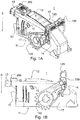
- the Figures 1A and 1B each show a perspective and a side view of a connector assembly 1.
- the connector assembly 1 is essentially composed of three components, elements and / or modules, namely a conductor guide device 10, a lever 100 and a CPA device 200.
- the connector assembly 1 can therefore also be referred to as a CPA-securable connector assembly and / or a CPA connector assembly.
- the conductor guide device 10 forms a base body and / or a base component of the connector assembly 1.
- the conductor guide device 10 can have a housing which is approximately cuboid and which encloses and / or contains electrical conductors (not shown in the figures). These electrical conductors guided inside the conductor guide device 10 are guided as far as a plug-in side 11 of the conductor guide device 10.
- the plug side 11 is designed as the lower side of the conductor guide device 10.
- the conductor guide device 10 is designed to be plugged into a slot (not shown) with the plug side 11 first in the plugging direction S in order to establish electrical connections between the guided electrical conductors and electrical contacts of the slot, i.e. to establish a plug connection between the conductor guide device 10 and the slot to manufacture.
- the plug-in direction S is formed approximately perpendicular to the plug-in side 11.
- the conductor guide device 10 extends essentially from the plug-in side 11 to a fastening side 12 which delimits the conductor guide device 10 in a direction facing away from the plug-in side 11.
- the fastening side 12 is that side of the conductor guide device 10 on which the lever 100 is placed in its locking position and / or on which the CPA device 200 is fastened.
- the fastening side 12 can be arranged approximately perpendicular to the insertion direction S.
- the conductor guide device 10 can furthermore have at least two side walls 17 which delimit the conductor guide device 10 to the outside between the plug-in side 11 and the fastening side 12.
- the side walls 17 can be arranged approximately parallel to the insertion direction S.
- the lever 100 is fastened to the conductor guide device 10 on two side walls 17 facing away from one another.
- the lever 100 can be pivoted about two pivot points 110, only one of which is in the Figures 1A and 1B is shown.
- the second pivot point 110 is formed on the side wall 17 facing away from the viewer. Normals to these two side walls 17, to which the lever 100 is attached to the conductor guide device 10, are referred to as lateral directions in the context of this description. These lateral directions are arranged approximately perpendicular to the plug-in direction S and thus approximately parallel to the plug-in side 11.
- the lever 100 is arranged in its unlocking position, in which it is supported on at least one unlocking stop 14.
- the unlocking stop 14 can be formed on one or more of the side walls 17.
- the unlocking stop 14 limits the pivoting movement of the lever 100 in the unlocking position.
- the lever 100 furthermore has a pivot end 120 which is arranged at an end of the lever 100 which is spaced apart from the pivot points 110.
- the lever 100 is fastened to the conductor guide device 10 in such a way that its pivot end 120 can be pivoted about the pivot points 110, in particular pivotable onto the fastening side 12 of the conductor guide device 10 Figures 1
- the pivot end 120 is pivoted away from the conductor guide device 10 and / or the fastening side 12 and is thus arranged at a distance therefrom, for example, against the plug-in direction S.
- the CPA device 200 is also fastened to the conductor guide device 10, namely movably fastened.
- the CPA device is arranged in its unlocked position.
- the CPA device 200 is basically designed to be displaceable along a portion of the fastening side 12. In the embodiment shown, however, the CPA device cannot easily be displaced from its unlocked position into the secured position, so as not to inadvertently block a locking of the lever 100.
- the CPA device 200 may be arranged adjacent to a cable guide 13, for example.
- the conductor guide device 10 can have the cable guide 13 for guiding cables, for example around to electrically connect electrical cables to the lines guided in the interior of the conductor guide device 10.
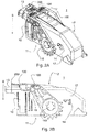
- Figures 2A and 2B show the same connector assembly 1 as Figures 1 .
- the lever 100 in the Figures 2 pivoted into its locking position.
- the lever 100 can for example be pivoted at its pivot end 120 around the at least one pivot point 110 on an outer surface of the conductor guide device 10, here on the fastening side 12.
- the connector assembly 1 is locked by a mechanism not shown in the figures with the slot, not shown, and thus fastened thereto.
- the connector assembly 1 in the Figures 1 shown unlocking position can be plugged with the plug side 11 first on the slot, not shown, this plug connection is not yet locked and thus relatively easy to detach from the slot. Only after the connector assembly 1 has been locked, that is, the lever 100 has been moved into the Figures 2 Locking position shown, the connector assembly 1 is so firmly connected to the slot that it can no longer be detached from it without being destroyed.
- the connector assembly 1 can be configured to be positively and / or non-positively connected to the slot in the locked state.
- At least one locking lug 15 formed on a side wall 17 of the conductor guide device 10 can engage in a recess of the lever 100 and thus secure the lever 100 against a lever releasing force.
- this is an easily detachable fuse, not a sufficiently stable fuse for the automotive sector.
- a sufficiently strong securing against lever release forces of, for example, more than 100 N or 200 N can only be achieved can be provided by means of the CPA device 200.
- the lever 100 is pivotable about a pivot axis which is arranged approximately parallel to the plug-in side 11 in the lateral direction.
- This swivel axis SW is for example in Figure 5A indicated by a dashed line.
- the pivot axis SW extends through the ladder guide device 10 through the two pivot points 110 of the lever 100.
- the shown fastening of the lever 100 at the two pivot points 110, i.e. on the two opposite side walls 17 of the ladder guide device 10, increases the stability and longevity of the lever movement .
- the lever 100 could also be pivotably connected to the conductor guide device 10 only at a single pivot point 110, for example only on one side wall 17.
- the lever 100 can basically be designed in the shape of a bow.
- the lever 100 extends from the first pivot point 110 along a first lever arm to the pivot end 120, which forms a bracket head.
- the pivot end 120 extends approximately parallel to the pivot axis SW of the lever 100 between the lever arm ends spaced apart from the pivot axis SW. From the pivot end 120, the lever 100 further extends along the second lever arm back to the second pivot point 110, which is hidden in the figures. While the pivot points 110 are formed on opposite side walls 17 of the conductor guide device 10, the pivot end 120 connects the two lever arms of the lever 100 to one another.
- the pivoting end 120 is pressed onto the fastening side 12, specifically in a spatial region which is arranged approximately adjacent to the CPA device 200.
- the CPA device 200 is still arranged in its unlocked position, just as in FIG Figures 1 . This means that although the lever 100 is arranged in its locking position, it is not yet secured there by the CPA device 200.
- Figures 3A and 3B show in a perspective view and in a side view the in the Figures 1 and 2 shown connector assembly 1.
- the CPA device 200 is moved to its secured position.
- the CPA facility 200 was used by the Figures 1 and 2
- the unlocking position shown is moved towards the pivot end 120 in such a way that it fixes the pivot end 120 in a form-fitting manner.
- the movement of the CPA device 200 from its unlocked position to the in the Figures 3 The securing position shown takes place by shifting along the fastening side 12.
- the movement of the CPA device 200 can take place by shifting along an outer surface of the conductor guide device 10.
- this sliding movement is a movement in a direction that is approximately perpendicular to the plug-in direction S (and here also perpendicular to the lateral directions) along the fastening side 12 facing away from the plug-in side 11.
- the CPA device 200 is preferably on this plug-in side 11 arranged facing away from the outside, in the exemplary embodiment that is on the fastening side 12, in order to form a particularly effective form fit there with the lever 100, more precisely the pivoting end 120 of the lever 100.
- the pivoting end 120 is particularly suitable for securing the lever 100 in its locking position because of the long lever travel.
- the connector assembly 1 is as shown in Figures 3A and 3B locked, ie the lever 100 is arranged in its locking position, and secured, ie the CPA device 200 is in its securing position, the connector assembly 1 can no longer be detached from the slot without being destroyed. However, this only applies as long as the CPA device 200 is not moved back into its unlocked position and the lever 100 is not moved back into its unlocked position.
- both the securing movement of the CPA device 200 and the locking movement of the lever 100 are reversible. This means that the locked and secured plug connection of the connector assembly 1 can also be released again, ie unlocking by moving the CPA device 200 into its unlocking position and by unlocking by moving the lever 100 into its unlocking position.
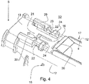
- Figure 4 shows a perspective view of a section of the conductor guide device 10 of the connector assembly 1, to which the CPA device 200 can be attached.
- the section without the CPA device 200 is shown here.
- Figure 4 shows a section of the conductor guide device 10 adjacent to the cable guide 13.
- a section of the fastening side 12 is shown, on which the pivoting end 120 of the lever 100 is placed in the locking position (cf. Figures 1 to 3 ).
- the conductor guide device 10 has a lever system 30.
- the lever system 30 is designed as a projection on which and / or around which the pivot end 120 is placed on the fastening side 12. It can be provided that a latching connection with the pivoting end 120 of the lever 100 can also be established on the lever system 30 in order to define the unsecured lever release force.
- a rail guide 20 is formed on the fastening side 12, between which a sliding surface 21 is formed.
- the sliding surface 21 is designed as an essentially flat outer surface of the fastening side 12.
- the sliding surface 21 serves as a base and / or support for the CPA device 200 (cf. Figures 1 to 3 ).
- the CPA device 200 can easily be moved on and along the sliding surface 21.
- a CPA latching means 16 can furthermore be formed approximately in the center of the sliding surface 21.
- the CPA latching means 16 can be designed as a latching lug, in particular as a pivotable latching lug, with which the CPA device 200 can be attached to the conductor guide device 10.
- the CPA latching means 16 can thus be designed as a CPA fuse.
- the sliding surface 21 is delimited on opposite sides by a rail guide 20.
- the conductor guide device 10 has two rail guides 20 running approximately parallel to one another.
- Each of the two rail guides 20 runs essentially parallel to and / or in the plane of one of the two side walls 17 of the conductor guide device 10.
- the rail guides 20 serve to guide slide rails of the CPA device 200, which are described in more detail in the following figures.
- the rail guides 20 are designed as elongated projections on the fastening side 12, which each block a movement of the CPA device 200 in at least one lateral direction.
- each rail guide 20 can comprise a type of outer wall which prevents a lateral movement of the CPA device 200 from the fastening side 12 beyond the respective immediately adjacent side wall 17.
- each of the rail guides 20 can have an overlap which at least partially overlaps the CPA device 200 in the assembled state in such a way that the CPA device 200 is clamped between the fastening side 12 (more precisely the sliding surface 21) and this overlap of the rail guides 20.
- the overlap of the rail guide 20 is arranged on a side of the CPA device 200 facing away from the fastening side 12 in such a way that the overlaps point in the direction of the respective other rail guide 20. The overlaps thus prevent the CPA device from moving away from the fastening side 12, that is to say from lifting off the fastening side 12 in a direction that is approximately perpendicular to the fastening side 12.
- the encroachments can in particular limit a movement of the CPA device 200 counter to the plug-in direction S, while the fastening side 12 or more precisely the sliding surface 21 limits a movement of the CPA device 200 in the plug-in direction S.
- the overlaps on the end of the outer walls of the rail guides 20 facing away from the fastening side 12 can thus make an important contribution to fixing the CPA device 200 in the effective direction of the form fit with the pivoting end 120 and / or in the unlocking direction.
- the elements of the rail guide 20 and the sliding surface 21 described so far thus limit the possibilities of movement of the CPA device 200 in two lateral directions guided perpendicular to the insertion direction S beyond the side walls 17 and both in and against the insertion direction S.
- the CPA device 200 can be attached to the ladder guide device 10 in such a way that the sliding movement of the CPA device 200 is limited both in the secured position and in the unlocked position.
- the CPA device 200 can therefore essentially only execute a linear movement, but neither beyond the safety position nor beyond the unlocking position.
- stops can be provided, for example, against which the CPA device 200 strikes in the secured position and / or in the unlocked position.
- One of these stops can be at least one release stop 24, which is shown in Figure 4 is shown.
- the unlocking stop 24 is designed in the illustrated embodiment as a curved projection between the rail guide 20 and the lever system 30 on the fastening side 12, in particular adjacent to and / or laterally adjacent to the sliding surface 21.
- the function of the unlocking stop 24, which here on both lateral sides , that is to say on the two opposite side walls 17, is described in more detail with reference to the following figures.
- a safety stop 23 can also be formed on the rail guide 20, which extends as an extension of the overlap on the outer wall of the rail guide towards the interior of the conductor guide device 10 on a side of the CPA device 200 facing away from the fastening side 12 Extension of the above-described overlap of the rail guide 20 in the direction of the respective other rail guide 20.
- the function of the securing end stop 23 is also described in more detail below with reference to the following figures.
- the Conductor guide device 10 Approximately parallel to the outer walls of the rail guides 20, the Conductor guide device 10 has two swivel spaces 22, which are designed as recesses in the sliding surface 21 and each adjoining the outer walls of the rail guides 20.
- the pivoting spaces 22 serve for pivoting slide rails of the CPA device 200, which are described in more detail with reference to the following figures.
- both the rail guides 20 and the pivoting spaces 22 extend approximately parallel to one another, specifically parallel to the linear direction of movement of the CPA device 200, in which the CPA device can be moved from its secured position to its unlocked position and back.
- the conductor guide device 10 has exactly two rail guides 20, two securing end stops 23, two unlocking end stops 24 and two pivoting spaces 22.
- FIG. 11 shows a perspective view of the lever 100 of the connector assembly 1.
- the lever 100 is arranged and fastened on the connector assembly 1 so as to be pivotable with respect to its pivot axis SW.
- the pivot axis SW extends through the two pivot points 110 which, in the assembled state, are arranged on opposite sides, more precisely on the side walls 17, of the conductor guide device 10.
- the lever 100 has two lever arms 140 which each extend approximately from one of the pivot points 110 to the pivot end 120.
- a latching receptacle 141 can be formed as a recess which is used to receive the in the Figures 2 locking lug 15 shown is formed.
- a toothing 150 is formed on each of the lever arms 140.
- the toothing 150 can comprise a plurality of teeth and in particular be designed similarly to a section of a gearwheel.
- the toothing 150 is configured in a manner not shown in the figures To engage the counterpart shown at the slot in such a way that the plug side 11 is locked at the slot, and thus the connector assembly 1 is locked at the slot.
- the toothing 150 is arranged on an end of the lever arms 140 facing away from the pivot end 120.
- the lever 100 has a bearing surface 160.
- the support surface 160 is slightly angled with respect to the direction in which the lever arms 140 extend.
- the support surface 160 is angled with respect to the lever arms 140 that it is in the Figures 2 and 3
- the shown locking position of the lever 100 is formed and aligned approximately parallel to the outer surface of the conductor guide device 10, more precisely the fastening side 12.
- the support surface 160 can be placed at least partially flat on the fastening side 12 in the locking position, cf. Figures 2 and 3 .
- a projection tongue 130 is also formed approximately in the center of the lever 100.
- the projection tongue 130 can comprise that lever point of the lever 100 which is most distant from the pivot axis SW.
- the projection tongue 160 can be designed as an extension of the pivot end 120 and / or the support surface 160 approximately in the direction away from the pivot axis SW.
- Figure 5B shows an enlargement of the pivot end 120 of the lever 100 in a perspective view.
- the projection tongue 130 is designed as a flat extension of the pivot end 120 and / or the support surface 160.
- a through opening 131 is furthermore formed at the pivot end 120, which through-opening 131 completely penetrates the pivot end 120 and / or the support surface 160 and / or the projection tongue 130.
- the through opening 131 is arranged essentially parallel to the plug-in direction S.
- the projection tongue 130 is arranged essentially parallel to and / or at least partially resting on the fastening side 12.
- the protrusion tongue 130 may be the furthest from the Pivot points 110 include spaced point of the lever 100.
- Figures 6A, 6B and 6C show the CPA device 200 in a perspective view, in a top view in the insertion direction S and in a side view in a lateral direction.
- the CPA device 200 has a sliding base 260 which is displaceable on the sliding surface 21 of the ladder guide device 10 (see also FIG Figure 4 ).
- the sliding base 260 can be designed to be essentially completely flat in order to be easily displaceable relative to the sliding surface 21.
- the CPA device 200 is designed to be arranged with the sliding base 260 on the sliding surface 21 of the conductor guide device 10.
- the CPA device 200 furthermore has a base 250 which is designed as a thickening and which extends from the sliding base 260 against the insertion direction S. Essentially all of the components of the CPA device 200 are formed on the base 250. Furthermore, the base 250 is thickened in such a way that the base 250 can be contacted by a finger of an operator in order to easily move the entire CPA device 200.
- the CPA device 200 has two slide rails 240, which in an assembled state of the connector assembly 1 inside the in Figure 4 rail guides 20 shown are arranged.
- the slide rails 240 extend approximately parallel to one another away from the base 250 along the slide base 260.
- each of the slide rails 240 is arranged approximately perpendicular to the insertion direction S.
- the slide rails 240 extend away from the base 250, for example along the fastening side 12 and in the direction of the lever 100 (see also FIG Figures 3 ).
- the slide rails 240 each have a thickening 241 which extends away from the sliding base 260 counter to the insertion direction S as a thickening.
- Each of the slide rails 240 is only on one side Base 250 attached, while the other end facing away from the base 250 can be resiliently pivoted as a free end.
- the thickening 241 is formed at the free end of the slide rails 240.
- each slide rail 240 has a stop step 242 on the side of the thickening 241 which faces the free end and thus the lever 100 in the assembled state.
- each thickening 241 On the side facing the base 250, each thickening 241 has a shoulder 243. The mode of operation of the thickening 241, the shoulder 243 and the stop step 242 is described in more detail with reference to the following figures.
- a first projection element 210 and a second projection element 220 of the CPA device 200 also extend away from the base 250 in the direction of the lever 100, i.e. in the assembled state approximately parallel to the fastening side 12.
- the second projection element 220 extends essentially along it of the sliding base 260.
- the second protrusion element 220 can essentially form the sliding base 260 (for example together with the undersides of the sliding rails 240).
- the first projection element 210 can be arranged at a distance from the second projection element 220 counter to the insertion direction S and can extend approximately parallel to the second projection element 220, that is to say in the assembled state in the direction of the lever 100.
- the two projection elements 210 and 220 form (cf., for example, those in Figure 6C side view shown) a receptacle 230 between them.
- the receptacle 230 extends in the plug-in direction S between the two projection elements 210 and 220.
- the receptacle 230 serves to receive the projection tongue 130 of the lever 100 (cf. Figures 5 ).
- Each of the two projection elements 210 and 220 is essentially designed in the form of a plate, the plates in the assembled state being designed essentially parallel to the fastening side 12 and thus to an outer surface of the conductor guide device 10.
- a latching recess 261 is formed in the second projection element 220, which in the assembled state with the, for example, in FIG Figure 4 CPA locking means 16 shown cooperates.
- the receptacle 230 is designed such that it widens in the direction of the lever 100 and / or away from the base 250. In the exemplary embodiment shown, this is brought about by a bevel 211 on the first projection element 210.
- the bevel 211 enlarges the receptacle 230 in the direction of the lever 100.
- Each of the slide rails 240 has an outer contour 244, which is formed, for example, as a bulge and / or a projection in the direction which, in the assembled state, faces the side walls of the rail guide 20.
- this outer contour 244 can be formed at the end of the slide rails 240 which is fastened to the base 250.
- the outer contours 244 are therefore shown as protrusions in lateral directions.
- the lateral directions are directions perpendicular to the insertion direction S, which additionally form approximately normals to the opposite side walls 17 (cf., for example Figure 1A ).
- the outer contours 244 can be designed as rounded projections, that is to say without hooks and / or step-free, in order to enable safe sliding and / or sliding in the rail guides 20.
- Figures 7A, 7B and 7C each show a section through a detail of the connector assembly 1. The section is taken through one of the two slide rails 240 of the CPA device 200. It is in the three Figures 7A, 7B and 7C the connector assembly 1 is shown in a different state in each case: In Figure 7A the lever 100 is unlocked and the CPA device 200 is unlocked, just as in FIG Figures 1 . In Figure 7B the lever 100 is locked and the CPA device 200 is unlocked, just as in FIG Figures 2 . In Figure 7C the lever 100 is locked and the CPA device 200 secured, as in FIG Figures 3 .
- the section in the figures is guided precisely in the center through one of the slide rails 240 in such a way that the insertion direction S is arranged parallel to the cutting plane.
- the cutting plane is furthermore essentially parallel to and between the two side walls 17 the connector assembly 1 (see Figures 1 to 3 ).
- each slide rail 240 is arranged exactly above the pivoting space 22 assigned to it. This means that the slide rail 240 can be pivoted into the pivoting space 22, in particular with its free end, on which the thickening 241 is also arranged. However, since no sufficient pivoting force acts on the slide rail 240, which is directed into the pivoting space 22, the slide rail 240 itself is arranged essentially in a straight line and is not pivoted.
- the sliding floor 260 (cf. Figures 6 ) flat on the sliding surface 21 of the conductor guide device 10 (cf. also Figure 4 ).
- the CPA device 200 is arranged in its unlocked position.
- Each of the slide rails 240 is guided in the respective rail guides 20 in such a way that the slide rail 240 in the plug-in direction S between the overlap of the rail guide 20 and the fastening side 12 is held.
- the safety stop 23 in particular engages over the slide rail 240 and thus prevents the CPA device 200 from lifting against the plug-in direction S.
- both overlaps of the rail guides 20 engage over the two respectively arranged therein Slide rails 240, so that the CPA device 200 is held essentially over the entire surface on the fastening side 12 of the conductor guide device 10.
- Figure 7A further shows that the slide rail 240 strikes with its stop step 242 on an edge of the unlocking stop 24 of the ladder guide device 10 facing the CPA device. This has the effect that the CPA device 200 cannot inadvertently be moved out of its unlocked position into the secured position, that is to say here in the direction of the lever system 30.
- the shoulder 243 of the thickening 241 can abut the securing end stop 23 at least in some areas in order to prevent a movement of the CPA device 200 in the opposite direction, that is, away from the lever stop 30 further towards the cable guide 13.
- the securing end stop 23 can contribute to the definition of the unlocking position.
- FIG 7B shows how in contrast to the Figure 7B the lever 100 is pivoted into its locking position, just as in FIG Figures 2 shown. In its locking position, the pivot end 120 rests against the lever system 30. The lever system 30 serves to define the locking position of the lever 100.
- a deflection extension 121 is also formed at the pivot end 120.
- the deflection extension 121 is formed on the side of the pivot end 120 facing the conductor guide device 10 and points in the insertion direction S to the fastening side 12.
- the deflection extension 121 presses in the direction shown in FIG Figure 7B position shown approximately in the insertion direction S on the thickening 241 of the slide rail 240.
- the deflection extension 121 can act somewhere in the vicinity of the free end on the slide rail 240 so that the slide rail 240 at least on its free end is pivoted a little way into the pivoting space 22.
- the slide rail 240 is deflected at least to such an extent that the stop step 242 no longer rests on the unlocking stop 24. This unblocks the CPA device 200.
- the CPA device 200 can be pushed in the direction of the lever stop 30 until the base 250 strikes the securing end stops 23. These thus define the security position as in Figure 7C shown.
- the slide rail 240 is swiveled back into its rest position, since here the deflection extension 121 no longer rests on the thickening 241, but on a thinner section of the slide rail 240. This no longer causes the slide rail 240 to deflect.
- the shoulder 243 of the thickening 241 continues to rest against the unlocking stop 24 with its side facing the base 250.
- the unlocking stop 24 is at the same time a certain stop for the locking position.
- the unlocking stop 24 can interact with the shoulder 243 in such a way that there is a certain resistance to unintentional opening of the CPA device 200 from the secured position into the unlocked position.
- the CPA device 200 on the base 250 can be pulled away from the pivoting end 120, for example in the direction of the cable guide 13.
- the shoulder 243 with its inclined surface cooperates with an oppositely directed bevel of the release stop 24, that the slide rail 240 is pivoted into the pivoting space 22, similar to that in FIG Figure 7B situation shown. This enables the CPA device 200 to be opened and unlocked.
- Figures 8A, 8B and 8C show exactly that in the Figures 7A to 7C shown states of the connector assembly 1, but along a different cutting plane.
- the section is placed approximately centrally through the CPA device 200, the lever 100 and the conductor guide device 10, specifically parallel to that in the Figures 7A to 7C section plane shown.
- the sectional plane shown no longer passes through one of the slide rails 240, but rather centrally through both the first projection element 210 and the second projection element 220 of the CPA device 200 exactly between the side walls 17.
- the lever 100 is not shown because it is arranged in its unlocked position.
- the lever 100 is thus not in the Figures 8A shown section swiveled in.
- the side of the second projection element 220 facing the conductor guide device 10 rests on the sliding surface 21.
- the second projection element 220 rests in particular on the CPA latching means 16 (cf. Figure 4 ) whose locking lug engages in the locking recess 261 in the sliding base 260 of the CPA device 200.
- the CPA locking means 16 secures the CPA device 200 in a captive manner on the conductor guide device 10.
- the locking lug of the CPA locking means 16 in particular prevents the CPA device 200 from being moved in the direction of the cable guide 13 and away from the lever stop 30.
- the CPA latching means 16 is thus designed as a stop which defines the unlocking position of the CPA device 200 in the direction away from the lever 100.
- Figure 8B shows the connector assembly 1, the lever 100 being pivoted in its locking position onto the fastening side 12 of the conductor guide device 10.
- the protrusion tongue 130 of the pivot end 120 is placed on the second protrusion element 220, which in turn rests on the fastening side 12.
- the through opening 131 does not yet rest on the second projection element 220.
- the through opening 131 penetrates the pivot end 120 in the locking position essentially parallel to the plug-in direction S. In this state, a cavity is formed between the end of the through opening 131 facing the conductor guide device 10 and the conductor guide device 10.
- Figure 8C shows how the CPA device 20 is pushed towards the lever 100 in such a way that the projection tongue 130 is received in the receptacle 230 which the CPA device 200 forms between the first projection element 210 and the second projection element 220.
- the receptacle 230 extends here in particular in the plug-in direction S, ie in a direction approximately perpendicular to the fastening side 12 of the conductor guide device 10.
- the shown locking position of the lever 100 is not necessarily designed to be free of play.
- the protrusion tongue 130 may not have to rest completely on the second protrusion element 220, but rather may be arranged somewhat at a distance from it.
- this play in the plug-in direction S of the pivot end 120 is reduced and / or no longer present at the latest when the securing position is set.
- the protrusion tongue 130 is held essentially without play between the first protrusion element 210 and the second protrusion element 220 in the receptacle 230.
- the first projection element 210 forms a form fit with the projection tongue 130, which prevents the lever 100 from being unlocked and / or counteracts it.
- the bevel 211 can simplify threading of the projection tongue 130.
- the bevel 211 acts on a projection tongue 130 which tapers towards the tip, for example, in such a way that the projection tongue 130 is safely guided into the interior of the receptacle 230.
- the second projection element 220 is arranged so that it is visible through the through opening 131. This provides a mechanical and clearly visible display which signals that the connector assembly 1 is both locked and secured.
- Figure 9 shows a perspective view of a section of the connector assembly 1 in a locked and secured position.
- the perspective view also shows how the second projection element 220 is visible through the through opening 131 in the pivot end 120.
- the through opening 131 is here arranged at the end of the projection tongue 130 which is adjacent to the projection tongue 130 on the side facing away from the CPA device 200. This is precisely the direction in which the second projection element 220 is pushed when the CPA device 200 is moved from the unlocking position into the locking position.
- the second protrusion element 220 can be embodied in a signal color such as red, for example, in order to improve the display properties.
- Figure 9 is shown in perspective how the base 250 strikes the two securing end stops 23 of the rail guides 20 in the securing position. It is also shown how the pivot end 120 engages behind the lever system 30 from one of the pivot axis SW (cf. Figure 5A ) facing away, that the lever stop 30 defines the locking position of the lever 100.
- Figure 10 shows a sectional view through the CPA device 200 guided in the rail guide 20 of the ladder guide device 10 in the unlocked position.
- the sectional view is essentially in the plugging direction S on the section shown directed.
- the cutting plane is arranged approximately parallel to the surface of the fastening side 12 and runs both through the rail guides 20 and through the slide rails 240.
- Figure 10 shows how the CPA locking means 16 engages in the locking recess 261 in order to secure the CPA device 200 in its unlocked position.
- the slide rails 240 are each arranged above the pivoting space 22.
- the pivoting spaces 22 are formed somewhat longer than the slide rails 240 themselves, in order to also permit the movement of the as in FIG Figure 7B to enable pivoted slide rails 240 shown in the direction of the lever stop 30.
- the slide rails 240 are not completely flat on their outer sides facing the rail guides 20, but instead each have an outer contour 244 there, which can be designed as a bulge, for example.
- the outer contours 244 of the slide rails 240 interact with the inner contours of the rail guides 20 in such a way that they define a displacement force that is necessary to move the CPA device 200 from its inside Figure 10 shown unlocking position in their locking position and / or vice versa.
- the rail guide 20 can each have two indentations, one for defining the unlocking position and a second indentation arranged offset thereto, which in the safety position accommodates the outer contour 244 of the respectively adjacent slide rail 240.
- the displacement force for moving the CPA device 200 is thus defined in a simple and mechanical manner by the outer contours 244 and the inner contours of the rail guides 20.
- the embodiment shown in the figures enables a very user-friendly connector assembly 1 with a CPA function.
- the CPA device 200 In the securing position, the CPA device 200, more precisely the first projection 210, engages behind the lever 100, more precisely the projection tongue 130, on a side of the pivot end 120 facing away from the conductor guide device 10.
Landscapes
- Details Of Connecting Devices For Male And Female Coupling (AREA)
Abstract
Description
- Die Erfindung betrifft eine Steckverbinderbaugruppe mit einer Leiterführungseinrichtung, einem Hebel und einer CPA-Einrichtung. Die Erfindung betrifft weiterhin ein Stecksystem mit einer Steckverbinderbaugruppe und einem Steckplatz sowie ein Verfahren zum Sichern einer Steckverbinderbaugruppe an einem Steckplatz.
- Elektrische Steckverbinder können als eine CPA-Steckverbinderbaugruppe mit mehreren Elementen und/oder Modulen ausgebildet sein und eine Leiterführungseinrichtung aufweisen als ein Hauptmodul und/oder Hauptelement und/oder Hauptbauteil des Steckverbinders. Die Leiterführungseinrichtung führt in ihrem Inneren elektrische Leiter und/oder elektrische Kontakte. Die Steckverbinderbaugruppe weist zumindest einen Hebel als ein zweites Modul und/oder Element und/oder Bauteil auf, mit welchem die Leiterführungseinrichtung in einer Steckverbindung mit einem Steckplatz verriegelt werden kann. Die Verriegelung ist als Schutz vor einem unbeabsichtigten Lösen der Steckverbindung konfiguriert. Als ein drittes Element und/oder Modul und/oder Bauteil weist die Steckverbinderbaugruppe weiterhin eine CPA-Einrichtung auf. Dabei steht "CPA" als eine Abkürzung für das englische "connector position assurance". Die CPA-Einrichtung wird benutzt, um den Hebel in der verriegelten Position zu sichern. Dadurch wird verhindert, dass sich der Hebel von seiner Verriegelungsposition in eine Entriegelungsposition bewegt, wodurch die Leiterführungseinrichtung und somit die Steckverbinderbaugruppe entriegelt wird und sich lösen kann vom Steckplatz.
- Derartige Stecker mit CPA-Einrichtungen werden insbesondere im Automotive-Bereich genutzt, z.B. als ABS-Steckverbinder, also Antiblockiersystemsteckverbinder.
- Aus dem Stand der Technik sind CPA-Steckverbinderbaugruppen bekannt, bei denen der Hebel in seiner Verriegelungsposition von einer Rastnase fixiert wird, welche an der Leiterführungseinrichtung ausgebildet ist. Ab einer ausreichenden Krafteinwirkung kann der Hebel jedoch zurückbewegt werden von seiner Verriegelungsposition in seine Entriegelungsposition unter Auslenkung der Rastnase, welche dann den Hebel freigibt. In diesen vorbekannten Steckverbinderbaugruppen wird eine CPA-Einrichtung dazu benutzt, dieses Auslenken der Rastnase zu verhindern und dadurch den Hebel in seiner verrasteten Verriegelungsposition zu sichern. Nur wenn die CPA-Einrichtung von der Rastnase wegbewegt wird und die Rastnase freigibt, kann auch der Hebel aus seiner Verrieglungsposition herausbewegt werden.
- Die vorbekannten CPA-Einrichtungen weisen den Nachteil auf, dass sie auf die Rastnase einwirken, welche elastisch beweglich ist und durch die Einwirkung belastet wird. Dies kann zu einem Verschleiß und bei wiederholter Nutzung sogar zu einem Abbrechen der Rastnase führen.
- Der Erfindung liegt die Aufgabe zugrunde, eine verbesserte Steckverbinderbaugruppe mit CPA-Einrichtung bereitzustellen. Beispielsweise kann die Aufgabe die Bereitstellung einer alternativen, verbesserten und/oder verschleißärmeren Steckverbinderbaugruppe mit CPA-Einrichtung sein.
- Diese Aufgabe wird durch die Gegenstände der unabhängigen Ansprüche gelöst. Bevorzugte Ausführungsformen sind die Gegenstände der abhängigen Ansprüche.
- Ein Aspekt betrifft eine Steckverbinderbaugruppe mit einer Leiterführungseinrichtung, einem Hebel und einer CPA-Einrichtung. Dabei ist die Leiterführungseinrichtung dazu konfiguriert, eine Steckverbindung mit einem Steckplatz derart einzugehen, dass in der Leiterführungseinrichtung geführte elektrische Leiter elektrische Kontakte des Steckplatzes kontaktieren. Der Hebel ist an der Leiterführungseinrichtung angeordnet und zwischen einer Verriegelungsposition, in welcher der Hebel die Leiterführungseinrichtung in der Steckverbindung mit dem Steckplatz verriegelt, und einer Entriegelposition, in welcher die Leiterführungseinrichtung vom Steckplatz lösbar ist, beweglich. Die CPA-Einrichtung ist an der Leiterführungseinrichtung angeordnet und beweglich zwischen einer Sicherungsposition und einer Entsicherungsposition. Die CPA-Einrichtung bildet in ihrer Sicherungsposition einen Formschluss mit dem Hebel zum Sichern und/oder Fixieren des Hebels in seiner Verriegelungsposition.
- Die Steckverbinderbaugruppe kann als eine CPA-Steckverbinderbaugruppe der eingangs genannten Art und/oder als ein mehrpoliger Steckverbinder ausgebildet sein, insbesondere als ein mehrpoliger Steckverbinder für den Automotive-Bereich. Die Steckverbinderbaugruppe kann insbesondere als eine ABS-Steckverbinderbaugruppe ausgebildet sein, also eine Steckverbinderbaugruppe für das Antiblockiersystem eines Kraftfahrzeugs. Die Steckverbinderbaugruppe ist zumindest dreiteilig aufgebaut, wobei die Leiterführungseinrichtung als Basisbauteil und/oder Hauptbauteil der Steckverbinderbaugruppe ausgebildet ist, an welcher sowohl der Hebel als auch die CPA-Einrichtung als zweites und drittes Bauteil befestigt und angeordnet sind. Im Inneren der Leiterführungseinrichtung ist eine Mehrzahl elektrischer Leiter geführt, welche im Inneren der Leiterführungseinrichtung hin zu einer Steck- und/oder Verbindungsseite der Leiterführungseinrichtung geführt sind. An dieser Steck- und/oder Verbindungsseite der Leiterführungseinrichtung ist die Leiterführungseinrichtung dazu ausgebildet, so auf den Steckplatz gesteckt zu werden, dass die im Inneren geführten elektrischen Leiter elektrische Kontakte des Steckplatzes elektrisch und/oder mechanisch kontaktieren. Der Steckplatz kann zum Beispiel als eine Buchse und/oder komplementärer Steckverbinder ausgebildet sein und/oder eine Platine aufweisen, mit der die Steckverbinderbaugruppe elektrisch verbindbar ist.
- Der Hebel ist an der Leiterführungseinrichtung beweglich befestigt, insbesondere verschwenkbar an und/oder um eine Schwenkachse und/oder zumindest einen Schwenkpunkt. Dabei kann der Hebel z.B. bügelartig ausgebildet sein und an zwei Schwenkpunkten an seiner Schwenkachse an der Leiterführungseinrichtung verschwenkbar befestigt sein. Der Hebel ist beweglich zwischen seiner Verriegelungsposition und seiner Entriegelposition. Dabei ist der Hebel reversibel beweglich, d.h. mit dem Hebel kann die Steckverbinderbaugruppe am Steckplatz sowohl verriegelt als auch entriegelt werden.
- Im unkontaktierten und somit uneingesteckten Zustand ist der Hebel normalerweise in seiner Entriegelposition angeordnet. Zugleich ist die CPA-Einrichtung in ihrer Entsicherungsposition angeordnet. Zum Herstellen der Steckverbindung wird zunächst die Leiterführungseinreichtung mit ihrer Steck- und/oder Verbindungsseite auf den Steckplatz aufgesetzt. Anschließend wird der Hebel von seiner Entriegelposition in seine Verriegelungsposition bewegt. In dieser Verriegelungsposition verriegelt der Hebel die Leiterführungseinrichtung in Steckverbindung mit dem Steckplatz. Dabei kann die Steckverbinderbaugruppe so konfiguriert sein, dass die Steckverbindung selber erst mit der Verriegelung hergestellt wird. Dabei kann die Leiterführungseinrichtung nicht mehr zerstörungsfrei von dem Steckplatz abgesteckt werden, solange der Hebel in seiner Verriegelungsposition angeordnet ist. In der Verriegelungsposition besteht eine mechanische und/oder formschlüssige und/oder kraftschlüssige Verbindung zwischen der Leiterführungseinrichtung und dem Steckplatz. In der Verriegelungsposition verhindert der Hebel somit ein unbeabsichtigtes Lösen der Steckverbindung.
- Da der Hebel reversibel zwischen der Verriegelungsposition und der Entriegelungsposition hin und her bewegbar ist, kann sich der Hebel unbeabsichtigt aus seiner Verriegelungsposition lösen. Ein solches Entriegeln kann z.B. durch ein von einem Fahrzeugmotor und/oder von Fahrbewegungen verursachten Rütteln und/oder Vibrieren bewirkt werden. Deswegen kann der Hebel zumindest mittels einer gewissen kraft-, reib- und/oder formschlüssigen Grundverbindung an der Leiterführungseinrichtung gesichert sein. Diese Grundverbindung ist jedoch nur bis zu einer vorbestimmten, vergleichsweise kleinen Hebellösekraft ausgelegt, da die Hebelbewegung ja grundsätzlich reversibel sein soll. Beispielsweise kann die vorbestimmbare Hebellösekraft zum Lösen des Hebels aus seiner Grundverbindung mit der Leiterführungseinrichtung von etwa 15 N bis etwa 150 N betragen, bevorzugt von etwa 80 N bis etwa 120 N. Da eine solche Hebellösekraft z.B. bei Fahrzeugbewegungen unbeabsichtigt auf den Hebel einwirken kann, weist die Steckverbinderbaugruppe zusätzlich die CPA-Einrichtung auf.
- Die CPA-Einrichtung ist ebenfalls beweglich an der Leiterführungseinrichtung befestigt. Die CPA-Einrichtung ist zwischen der Sicherungsposition und der Entsicherungsposition reversibel beweglich. Zumindest wenn der Hebel in seiner Verriegelungsposition angeordnet ist, kann die CPA-Einrichtung von ihrer Entsicherungsposition in ihre Sicherungsposition bewegt werden, in welcher der Formschluss zwischen der CPA-Einrichtung und dem Hebel gebildet wird. Dieser Formschluss verhindert ein unbeabsichtigtes Bewegen des Hebels aus der Verriegelungsposition heraus und somit ein unbeabsichtigtes Entriegeln der Leiterführungseinrichtung.
- Die Steckverbinderbaugruppe weist den Vorteil auf, dass durch den Formschluss zwischen der CPA-Einrichtung und dem Hebel unmittelbar die Entriegelungsbewegung des Hebels blockiert ist, also eine Bewegung des Hebels von seiner Verriegelungsposition in seine Entriegelposition. Damit erfolgt die Sicherung des Hebels nicht (wie bei herkömmlichen CPA-Steckverbinderbaugruppen) indirekt über den Umweg einer Einwirkung auf eine Rastnase der Leiterführungseinrichtung, sondern mittels einer unmittelbaren Befestigung und/oder Fixierung des Hebels. Dadurch kann eine Belastung beweglicher und damit verschleißanfälliger Teile, wie zum Beispiel einer Rastnase der Leiterführungseinrichtung, reduziert und/oder vermieden werden.
- Die CPA-Einrichtung ist weiterhin auch von ihrer Sicherungsposition in ihre Entsicherungsposition zurückbeweglich. Dies bedeutet, dass der Formschluss zwischen dem Hebel und der CPA-Einrichtung wieder lösbar ist, so dass anschließend der entsicherte Hebel von seiner Verriegelungsposition zurück in seine Entriegelposition bewegbar ist. Dabei kann die Entriegelungsbewegung gegebenenfalls unter Aufbringung der dazu erforderlichen Hebellösekraft erfolgen. Dadurch wird ein reversibles Sichern und Entsichern der Steckverbindung zwischen der Steckverbinderbaugruppe, insbesondere der Leiterführungseinrichtung, einerseits und dem Steckplatz andererseits ermöglicht.
- Neben der formschlüssigen Sicherung kann die CPA-Einrichtung in der Sicherungsposition auch eine kraft- und/oder reibschlüssige Verbindung zwischen dem Hebel und der CPA-Einrichtung in der Sicherungsposition bereitstellen. Dadurch kann die Sicherung des Hebels in seiner Verriegelungsposition verstärkt werden.
- Die Befestigung der CPA-Einrichtung an der Leiterführungseinrichtung kann derart konfiguriert sein, dass die CPA-Einrichtung in eine Entriegelungsrichtung unbeweglich an der Leiterführungseinrichtung befestigt ist. Die Entriegelungsrichtung entspricht dabei der Richtung, in welcher der Hebel aus seiner Verriegelungsposition herausbewegt wird zum Entriegeln der Leiterführungseinrichtung. Eine derartige Befestigung der CPA-Einrichtung bewirkt, dass die formschlüssige Befestigung des Hebels mittels der CPA-Einrichtung verhindert, dass der mit der CPA-Einrichtung gesicherte Hebel relativ zur Leiterführungseinrichtung aus seiner Verriegelungsposition herausbewegbar ist. Der Formschluss kann dabei insbesondere in Entriegelungsrichtung wirken.
- In einer Ausführungsform weist die CPA-Einrichtung zumindest ein erstes Vorsprungelement auf, welches in der Sicherungsposition zumindest teilweise an einer der Leiterführungseinrichtung abgewandten Seite des Hebels angeordnet ist, wodurch der Formschluss zwischen der CPA-Einrichtung und dem Hebel bereitgestellt wird. In der gesicherten Position, also wenn der Hebel in seiner Verriegelungsposition und die CPA-Einrichtung in ihrer Sicherungsposition angeordnet ist, hintergreift das erste Vorsprungelement den Hebel an einer der Leiterführungseinrichtung abgewandten Seite. Die der Leiterführungseinrichtung abgewandten Seite ist eine Seite desjenigen Teilstücks des Hebels, welches den Formschluss mit der CPA-Einrichtung ausbildet. Das Teilstück kann z.B. als eine Vorsprungzunge des Hebels ausgebildet sein. In der gesicherten Position kann der Hebel somit zumindest teilweise zwischen der CPA-Einrichtung einerseits und der Leiterführungseinrichtung und/oder einem anderen Teil der CPA-Einrichtung andererseits angeordnet sein. Durch den Formschluss kann verhindert werden, dass der gesicherte Hebel von der Leiterführungseinrichtung wegbewegt wird. Dieses Wegbewegen des Hebels von der Leiterführungseinrichtung kann Bestandteil der Entriegelungsbewegung sein, also der Bewegung des Hebels von der Verriegelungsposition in die Entriegelposition. Durch den Formschluss wird die Bewegung des Hebels von seiner Verriegelungsposition in seine Entriegelposition durch das erste Vorsprungelement blockiert und/oder behindert.
- Gemäß einer Ausführungsform weist die CPA-Einrichtung zumindest ein zweites Vorsprungelement auf und der Hebel eine Durchgangsöffnung. Dabei ist das zweite Vorsprungelement in der Sicherungsposition durch die Durchgangsöffnung hindurch sichtbar. Dadurch kann eine visuelle Anzeige bereitgestellt werden zur Anzeige, ob die CPA-Einrichtung in ihrer Sicherungsposition angeordnet ist oder nicht. Dabei kann das zweite Vorsprungelement zumindest teilweise in einer Signalfarbe wie z.B. Rot ausgebildet sein, um die Sichtbarkeit des zweiten Vorsprungelements durch die Durchgangsöffnung hindurch zu erhöhen. Sofern das zweite Vorsprungelement durch die Durchgangsöffnung hindurch nicht sichtbar ist, befindet sich die CPA-Einrichtung auch noch nicht in ihrer Sicherungsposition. Hierbei kann das zweite Vorsprungelement in der Sicherungsposition unmittelbar benachbart zur Durchgangsöffnung angeordnet sein. Das zweite Vorsprungelement kann einen Außendurchmesser aufweisen, welcher größer als der Innendurchmesser der Durchgangsöffnung ausgebildet ist. Dies ermöglicht es dem zweiten Vorsprungelement, die Durchgangsöffnung in der Sicherungsposition vollständig zu hintergreifen und/oder auszufüllen. Hierbei ist es nicht erforderlich, dass das zweite Vorsprungelement jemals in die Durchgangsöffnung eingreift. Es kann bereits ausreichend sein, dass das zweite Vorsprungelement in der Sicherungsposition flächig benachbart zu einem und/oder anliegend an einen Teil des Hebels angeordnet ist, welcher von der Durchgangsöffnung durchdrungen wird. Somit kann mit einfachen mechanischen Mitteln eine effektive Anzeige bereitgestellt werden zum Überprüfen der Sicherung der verriegelten Steckverbindung.
- In einer Weiterbildung dieser Ausführungsform ist das zweite Vorsprungelement in der Sicherungsposition zumindest teilweise an einer der Leiterführungseinrichtung abgewandten Seite des Hebels angeordnet, wodurch der Formschluss zumindest teilweise zwischen der CPA-Einrichtung und dem Hebel bereitgestellt wird. In dieser Ausführungsform kann das zweite Vorsprungelement eine Doppelfunktion erfüllen.
- Diese Doppelfunktion ist jedoch nicht zwingend notwendig, der Formschluss kann auch durch ein anderes Bestandteil wie zum Beispiel das voranstehend erwähnte erste Vorsprungelement bereitgestellt werden.
- Gemäß einer Ausführungsform weist die CPA-Einrichtung zumindest eine Aufnahme zum Aufnehmen einer Vorsprungzunge des Hebels auf. In dieser Ausführungsform wird der Formschluss dadurch bereitgestellt, dass die Vorsprungzunge des Hebels in die Aufnahme der CPA-Einrichtung eingeführt wird. Die Vorsprungzunge kann dabei insbesondere an einem der Schwenkachse abgewandten Hebelende des Hebels angeordnet sein. Dies kann die sichernde Wirkung des Formschlusses aufgrund des Hebelgesetzes maximieren. Das Aufnehmen der Vorsprungzunge in die Aufnahme der CPA-Einrichtung kann durch die Bewegung der CPA-Einrichtung von ihrer Entsicherungsposition in ihre Sicherungsposition erfolgen, wobei die Leiterführungseinrichtung und der Hebel im Wesentlichen in ihrer Position verharren können, also kaum oder gar nicht bewegt werden müssen. Bei diesem Sichern kann sich allerdings zumindest die Position des Hebels leicht verändern, um die Vorsprungzunge genau in die Aufnahme einzuführen.
- In einer Weiterbildung begrenzt das erste Vorsprungelement die Aufnahme in einer der Leiterführungseinrichtung abgewandten Wirkrichtung und bildet in der Sicherungsposition den in dieser Wirkrichtung wirkenden Formschluss mit der Vorsprungzunge aus. Die Wirkrichtung kann hierbei die Wirkrichtung des Formschlusses und/oder die Entriegelungsrichtung sein. Hierbei wird die Vorsprungzunge des Hebels in der Sicherungsposition von dem ersten Vorsprungelement der CPA-Einrichtung im Formschluss befestigt und/oder fixiert. Dadurch wird auch der Hebel in seiner Verriegelungsposition befestigt und/oder fixiert.
- Gemäß einer Weiterbildung begrenzt das zweite Vorsprungelement die Aufnahme in einer der Leiterführungseinrichtung zugewandten Richtung. Diese zugewandte Richtung kann die Gegenrichtung zur Wirkrichtung des Formschlusses und/oder zur Entriegelungsrichtung sein. Hierbei können das erste Vorsprungelement und das zweite Vorsprungelement dazu ausgebildet sein, die Vorsprungzunge des Hebels beidseitig festzuhalten. Dies ermöglicht eine besonders sichere Aufnahme und somit Befestigung des Hebels in seiner Verriegelungsposition.
- In einer Weiterbildung ist die Vorsprungzunge in der Sicherungsposition so in der Aufnahme angeordnet, dass der Hebel in der Verriegelungsposition im Wesentlichen spielfrei relativ zur Leitungsführungseinrichtung angeordnet ist. Herkömmliche Steckverbinderbaugruppen weisen den Nachteil auf, dass der Hebel in seiner Verriegelungsposition ein Spiel relativ zur Leitungsführungseinrichtung aufweist. Dies kann zum Beispiel dadurch bedingt sein, dass der Hebel in seiner Verriegelungsposition durch eine bewegliche Rastnase der Leiterführungseinreichtung gesichert ist. Die Beweglichkeit der Rastnase kann zu dem Bewegungsspiel des Hebels führen. Dieses Bewegungsspiel kann aber auch dazu führen, dass sich der Hebel durch Vibrationen aufschaukelt, was z.B. im Resonanzfall zu einem unbeabsichtigten Lösen des Hebels führen kann. Dieses Problem löst die vorliegende Weiterbildung dadurch, dass die Vorsprungzunge im Wesentlichen spielfrei in der Aufnahme der CPA-Einrichtung gehalten wird. Dadurch ist auch der Hebel in seiner Verriegelungsposition spielfrei an der Leitungsführungseinrichtung angeordnet. Dies reduziert die Gefahr eines unbeabsichtigten Entriegelns des Hebels bei Vibrationen und/oder ähnlichen Krafteinwirkungen.
- Gemäß einer Weiterbildung weist die Aufnahme eine Aufweitung in Richtung aus der Aufnahme heraus auf und/oder die Vorsprungzunge weist eine Verjüngung in Richtung vom Hebel weg und/oder zur Aufnahme hinein auf. Die Aufweitung und/oder Verjüngung ist oder sind derart konfiguriert, dass ein Einfädeln und/oder Einführen der Vorsprungzunge in die Aufnahme erleichtert und/oder unterstützt wird. Insbesondere wenn der Hebel mit einem gewissen Spiel in seiner Verriegelungsposition gehalten ist, ist dessen Position und damit die Position der Vorsprungzunge nicht eindeutig definiert. Dies kann ein Einfädeln und/oder Einführen der Vorsprungzunge in die Aufnahme der CPA-Einrichtung verkomplizieren. Das Einführen wird erleichtert durch die Aufweitung und/oder die Verjüngung. Bevorzugt weist die Aufnahme sowohl die Aufweitung auf als auch die Vorsprungzunge die Verjüngung. Die Aufweitung und Verjüngung kann jeweils eine schräge Fläche beinhalten, wie z.B. schräge Flächen, die beim Einfädeln der Vorsprungzunge so aneinander abgleiten, dass die Vorsprungzunge sicher in ihre Sollposition in die Aufnahme eingeführt wird.
- In einer Ausführungsform weist die CPA-Einrichtung zumindest eine Gleitschiene auf, mit der die CPA-Einrichtung entlang einer Schienenführung der Leitungsführungeinrichtung beweglich ist zwischen der Sicherungsposition und der Entsicherungsposition. Alternativ kann die CPA-Einrichtung die Schienenführung und die Leitungsführungseinrichtung die Gleitschiene aufweisen. Bevorzugt weist die CPA-Einrichtung zwei Gleitschienen aufweiche in zwei Schienenführungen angeordnet sind. Die Schienenführungen können derart konfiguriert sein, dass sie lediglich eine Bewegung der CPA-Einrichtung zwischen der Sicherungsposition in die Entsicherungsposition und zurück erlauben. Diese Bewegung kann eine im Wesentlichen eindimensionale Bewegung sein, wobei die Schienenführung Bewegungen in die anderen beiden Dimensionen verhindert und/oder reduziert, d.h. in die Richtungen senkrecht zu dieser Sicherungsbewegungsrichtung. Dabei kann die Bewegung der CPA-Einrichtung zwischen Sicherungsposition und Entsicherungsposition eine Linearbewegung sein und insbesondere eine Verschiebung der CPA-Einrichtung entlang einer Außenoberfläche der Leitungsführungseinrichtung beinhalten. Ein oder mehr Endanschläge können vorgesehen sein, welche diese eindimensionale, etwa lineare Bewegung der CPA-Einrichtung entlang der Schienenführung ein- oder beidseitig begrenzen, z.B. in der Entsicherungsposition und/oder in der Sicherungsposition der CPA-Einrichtung.
- In einer Weiterbildung weist die zumindest eine Gleitschiene eine Außenkonfiguration auf, die entlang einer Innenkonfiguration der Schienenführung beweglich ist, wobei die Außenkonfiguration der Gleitschiene derart auf die Innenkonfiguration der Schienenführung abgestimmt ist, dass dadurch eine vorbestimmte Kraft zum Bewegen der CPA-Einrichtung definiert ist. Diese Kraft kann notwendig sein zum Bewegen der CPA-Einrichtung. Durch diese Kraft kann ein unabsichtliches Herausbewegen der CPA-Einrichtung aus der Sicherungsposition verhindert und/oder reduziert werden. In dieser Ausführungsform können zum Beispiel die Gleitschienen der CPA-Einrichtung an einer der Schienenführung zugewandten Außenfläche strukturiert ausgebildet sein, z.B. abgerundete Vorsprünge und/oder Einbuchtungen aufweisen, die beim Bewegen der CPA-Einrichtung mit abgerundeten Vorsprüngen und/oder Einbuchtungen der Schienenführung zusammenwirken können. Dadurch, d.h. durch die genaue Form der Ausbuchtungen und/oder Einbuchtungen, kann eine Reibkraft definiert werden, die zum Bewegen der CPA-Einrichtung zu überwinden ist. Gegebenenfalls kann dabei auch eine elastische Kraft definiert werden, beispielsweise zum Verformen der Gleitschiene und/oder der Schienenführung beim Bewegen der CPA-Einrichtung. Hierdurch kann die CPA-Einrichtung insbesondere in ihrer Sicherungsposition gesichert werden.
- Gemäß einer Ausführungsform weist die Steckverbinderbaugruppe eine CPA-Sicherung auf, welche die CPA-Einrichtung verliersicher an der Leitungsführungseinrichtung sichert. Die CPA-Sicherung kann beispielsweise ein Rastmittel beinhalten, welche die CPA-Einrichtung an der Leitungsführungseinrichtung sichert. Das Rastmittel kann beispielsweise eine an der Leiterführungseinrichtung ausgebildete Rastnase und/oder eine in der CPA-Einrichtung ausgebildete Rasteinsparung umfassen. Durch die CPA-Sicherung kann insbesondere eine Bewegung der CPA-Einrichtung über die Entsicherungsposition hinaus entlang der Schienenführung gestoppt und/oder behindert werden.
- In einer Ausführungsform ist die CPA-Einrichtung nur dann von der Entsicherungsposition in die Sicherungsposition bewegbar, wenn der Hebel in seiner Verriegelungsposition angeordnet ist. Dadurch wird verhindert, dass die CPA-Einrichtung unbeabsichtigt in die Sicherungsposition bewegt wird, bevor der Hebel verriegelt wird. Dann nämlich könnte die CPA-Einrichtung die Verriegelungsbewegung des Hebels behindern und/oder verhindern. Diese Konfiguration kann zum Beispiel durch zumindest einen Anschlag der CPA-Einrichtung realisiert werden, welcher von dem verriegelten Hebel so unterbrochen und/oder ausgelenkt werden kann, dass die CPA-Einrichtung von der Entsicherungsposition in die Sicherungsposition bewegbar ist. Ohne die Auslenkung und/oder Unterbrechung des Anschlags kann die CPA-Einrichtung nicht von der Entsicherungsposition in die Sicherungsposition bewegt werden.
- Ein Aspekt betrifft ein Stecksystem mit einer Steckverbinderbaugruppe nach dem voranstehend beschriebenen Aspekt und einem Steckplatz, mit welchem die Leiterführungseinrichtung eine Steckverbindung derart eingeht, dass die in der Leiterführungseinrichtung geführten elektrischen Leiter elektrische Kontakte des Steckplatzes kontaktieren. In der Steckverbindung ist der Hebel in seiner Verriegelungsposition angeordnet und die CPA-Einrichtung kann in ihrer Sicherungsposition angeordnet sein, um den Hebel und somit die Leiterführungseinrichtung in der Steckverbindung zu sichern. Hierbei kann der Steckplatz zum Beispiel als ein zugehöriger komplementärer Steckverbinder, als eine Buchse, und/oder als eine Platine mit einem Steckverbinder ausgebildet sein. Die Steckverbindung ist reversibel sicherbar mittels der CPA-Einrichtung der Steckverbinderbaugruppe. Weiterhin ist die Steckverbindung reversibel verriegelbar mittels des Hebels der Steckverbinderbaugruppe.
- Ein Aspekt betrifft ein Verfahren zum Sichern einer Steckverbinderbaugruppe mit einer Leitungsführungseinrichtung, einem Hebel und einer CPA-Einrichtung an einem Steckplatz mit den Schritten:
- Herstellen einer Steckverbindung zwischen der Leiterführungseinrichtung und dem Steckplatz derart, dass in der Leiterführungseinrichtung geführte elektrische Leiter elektrische Kontakte des Steckplatzes kontaktieren;
- Bewegen des Hebels, welcher an der Leiterführungseinrichtung angeordnet ist, von einer Entriegelposition, in welcher die Leiterführungseinrichtung vom Steckplatz lösbar ist, in eine Verriegelungsposition, in welcher der Hebel die Leiterführungseinrichtung in der Steckverbindung mit dem Steckplatz verriegelt;
- Bewegen der CPA-Einrichtung, welcher an der Leiterführungseinrichtung angeordnet ist, von einer Entsicherungsposition in eine Sicherungsposition; und
- Sichern und/oder Fixieren des Hebels in seiner Verriegelungsposition durch Ausbilden eines Formschlusses zwischen der CPA-Einrichtung und dem Hebel, während die CPA-Einrichtung in der Sicherungsposition angeordnet ist.
- Das Verfahren kann insbesondere mit einer Steckverbinderbaugruppe gemäß dem eingangs beschriebenen Aspekt realisiert werden. Deswegen betreffen sämtliche im Zusammenhang mit der Steckverbinderbaugruppe beschriebenen Merkmale und/oder Eigenschaften auch das Verfahren und umgekehrt.
- Die Schritte des Verfahrens müssen nicht zwangsweise in der voranstehend beschriebenen Reihenfolge und/oder nicht zwangsweise getrennt voneinander durchgeführt werden. Beispielsweise kann das Herstellen der Steckverbindung unter Bewegung des Hebels erfolgen. So kann beim Herstellen der Steckverbindung zunächst die Leiterführungseinrichtung auf den Steckplatz aufgesetzt werden, so dass lediglich ein mechanischer Kontakt hergestellt wird, ohne dass ein elektrischer Kontakt hergestellt wird. Die Steckverbindung unter elektrischer Kontaktierung kann beispielsweise beim Umlegen des Hebels hergestellt werden, also beim Bewegen des Hebels von seiner Entriegelungsposition in seine Verriegelungsposition. So kann das Bewegen und damit Verriegeln des Hebels auch eine Bewegung der Leiterführungseinrichtung in Steckrichtung auf den Steckplatz zu bewirken und/oder beinhalten. Erst nach dem Verriegeln des Hebels kann ein sicherer elektrischer Kontakt zwischen den elektrischen Leitungen der Steckverbinderbaugruppe und den elektrischen Kontakten des Steckplatzes hergestellt sein. Somit können die Schritte des Herstellens einer Steckverbindung und des Bewegens des Hebels zumindest teilweise zeitgleich erfolgen.
- Ein Aspekt betrifft die Verwendung der eingangs beschriebenen Steckverbinderbaugruppe zum Herstellen einer Steckverbindung mit einem Steckplatz.
- Im Rahmen dieser Erfindung können die Begriffe "im Wesentlichen" und/oder "etwa" so verwendet sein, dass sie eine Abweichung von bis zu 5% von einem auf den Begriff folgenden Zahlenwert beinhalten, eine Abweichung von bis zu 5° von einer auf den Begriff folgenden Richtung und/oder von einem auf den Begriff folgenden Winkel.
- Begriffe wie oben, unten, oberhalb, unterhalb, lateral, usw. beziehen sich - sofern nicht anders spezifiziert - auf die in den Figuren gezeigte Position des Gegenstandes, nicht zwangsweise das Bezugssystem der Erde.
- Die Erfindung wird nachfolgend anhand von in Figuren gezeigten Ausführungsbeispielen näher beschrieben. Hierbei können gleiche oder ähnliche Bezugszeichen gleiche oder ähnliche Merkmale der Ausführungsformen kennzeichnen. Einzelne in den Figuren gezeigte Merkmale können in anderen Ausführungsbeispielen implementiert sein. Es zeigen:
- Figur 1A
- eine perspektivische Ansicht einer Steckverbinderbaugruppe, deren Hebel in seiner Entriegelungsposition und deren CPA-Einrichtung in ihrer Entsicherungsposition angeordnet ist;
- Figur 1B
- eine Seitenansicht der in
Fig. 1A gezeigten Steckverbinderbaugruppe; - Figur 2A
- eine perspektivische Ansicht der Steckverbinderbaugruppe, deren Hebel in seiner Verriegelungsposition und deren CPA-Einrichtung in ihrer Entsicherungsposition angeordnet ist;
- Figur 2B
- eine Seitenansicht der in
Fig. 2A gezeigten Steckverbinderbaugruppe; - Figur 3A
- eine perspektivische Ansicht der Steckverbinderbaugruppe, deren Hebel in seiner Verriegelungsposition und deren CPA-Einrichtung in ihrer Sicherungsposition angeordnet ist;
- Figur 3B
- eine Seitenansicht der in
Fig. 3A gezeigten Steckverbinderbaugruppe; - Figur 4
- eine perspektivische Ansicht auf einen Ausschnitt einer Leiterführungseinrichtung der Steckverbinderbaugruppe,
- Figur 5A
- eine perspektivische Ansicht eines Hebels der Steckverbinderbaugruppe;
- Figur 5B
- eine perspektivische Ansicht eines Ausschnitts des Hebels;
- Figur 6A
- eine perspektivische Ansicht einer CPA-Einrichtung der Steckverbinderbaugruppe;
- Figur 6B
- eine Draufsicht auf die CPA-Einrichtung in Steckrichtung;
- Figur 6C
- eine Seitenansicht der CPA-Einrichtung etwa senkrecht zur Steckrichtung;
- Figur 7A
- eine Schnittansicht durch eine Gleitschiene der CPA-Einrichtung der Steckverbinderbaugruppe, wobei der Hebel in seiner Entriegelungsposition und die CPA-Einrichtung in ihrer Entsicherungsposition angeordnet ist;
- Figur 7B
- eine Schnittansicht durch eine Gleitschiene der CPA-Einrichtung der Steckverbinderbaugruppe, wobei der Hebel in seiner Verriegelungsposition und die CPA-Einrichtung in ihrer Entsicherungsposition angeordnet ist;
- Figur 7C
- eine Schnittansicht durch eine Gleitschiene der CPA-Einrichtung der Steckverbinderbaugruppe, wobei der Hebel in seiner Verriegelungsposition und die CPA-Einrichtung in ihrer Sicherungsposition angeordnet ist;
- Figur 8A
- eine Schnittansicht zentral durch die CPA-Einrichtung der Steckverbinderbaugruppe, wobei der Hebel in seiner Entriegelungsposition und die CPA-Einrichtung in ihrer Entsicherungsposition angeordnet ist;
- Figur 8B
- eine Schnittansicht zentral durch die CPA-Einrichtung der Steckverbinderbaugruppe, wobei der Hebel in seiner Verriegelungsposition und die CPA-Einrichtung in ihrer Entsicherungsposition angeordnet ist;
- Figur 8C
- eine Schnittansicht zentral durch die CPA-Einrichtung der Steckverbinderbaugruppe, wobei der Hebel in seiner Verriegelungsposition und die CPA-Einrichtung in ihrer Sicherungsposition angeordnet ist;
- Figur 9
- eine perspektivische Ansicht auf einen Ausschnitt der gesicherten Steckverbinderbaugruppe, und
- Figur 10
- eine Schnittansicht durch die in einer Schienenführung der Leiterführungseinrichtung geführte CPA-Einrichtung in Entsicherungsposition.
- Die
Figuren 1A und 1B zeigen jeweils eine perspektivische und eine Seitenansicht einer Steckverbinderbaugruppe 1. Die Steckverbinderbaugruppe 1 ist im Wesentlichen aus drei Bauteilen, Elementen und/oder Modulen aufgebaut, nämlich einer Leiterführungseinrichtung 10, einem Hebel 100 und einer CPA-Einrichtung 200. - Deswegen kann die Steckverbinderbaugruppe 1 auch als eine CPA-sicherbare Steckverbinderbaugruppe und/oder CPA-Steckverbinderbaugruppe bezeichnet werden.
- Die Leiterführungseinrichtung 10 bildet dabei einen Grundkörper und/oder ein Grundbauteil der Steckverbinderbaugruppe 1 aus. Die Leiterführungseinrichtung 10 kann ein Gehäuse aufweisen, das in etwa quaderförmig ausgebildet ist, und welches in den Figuren nicht gezeigte elektrische Leiter umschließt und/oder beinhaltet. Diese im Inneren der Leiterführungseinrichtung 10 geführten elektrischen Leiter werden bis zu einer Steckseite 11 der Leiterführungseinrichtung 10 geführt. In den
Figuren 1A und 1B ist die Steckseite 11 als die untere Seite der Leiterführungseinrichtung 10 ausgebildet. Die Leiterführungseinrichtung 10 ist dazu ausgebildet, mit der Steckseite 11 voran in Steckrichtung S auf einen nicht gezeigten Steckplatz gesteckt zu werden, um elektrische Verbindungen zwischen den geführten elektrischen Leitern und elektrischen Kontakten des Steckplatzes herzustellen, also um eine Steckverbindung zwischen der Leiterführungseinrichtung 10 und dem Steckplatz herzustellen. Die Steckrichtung S ist dabei etwa senkrecht zur Steckseite 11 ausgebildet. - Die Leiterführungseinrichtung 10 erstreckt sich im Wesentlichen von der Steckseite 11 bis hin zu einer Befestigungsseite 12, welche die Leiterführungseinrichtung 10 in einer der Steckseite 11 abgewandten Richtung begrenzt. Allgemein ist die Befestigungsseite 12 diejenige Seite der Leiterführungseinrichtung 10, auf welche der Hebel 100 in seiner Verriegelungsposition angelegt wird und/oder an welcher die CPA-Einrichtung 200 befestigt ist. Die Befestigungsseite 12 kann etwa senkrecht zur Steckrichtung S angeordnet sein. Die Leiterführungseinrichtung 10 kann weiterhin zumindest zwei Seitenwände 17 aufweisen, welche die Leiterführungseinrichtung 10 zwischen der Steckseite 11 und der Befestigungsseite 12 nach außen begrenzen. Die Seitenwände 17 können etwa parallel zur Steckrichtung S angeordnet sein.
- An zwei einander abgewandten Seitenwänden 17 ist der Hebel 100 an der Leiterführungseinrichtung 10 befestigt. Dabei ist der Hebel 100 um zwei Schenkpunkte 110 verschwenkbar, von denen lediglich einer in den
Figuren 1A und 1B gezeigt ist. - Der zweite Schwenkpunkt 110 ist an der dem Betrachter abgewandten Seitenwand 17 ausgebildet. Normalen auf diese beiden Seitenwände 17, an welchen der Hebel 100 an der der Leiterführungseinrichtung 10 befestigt, werden im Rahmen dieser Beschreibung als laterale Richtungen bezeichnet. Diese lateralen Richtungen sind etwa senkrecht zur Steckrichtung S angeordnet und somit etwa parallel zur Steckseite 11.
- In der in
Figur 1A und 1B gezeigten Situation ist der Hebel 100 in seiner Entriegelungsposition angeordnet, in welcher er sich an zumindest einem Entriegelungsanschlag 14 abstützt. Der Entriegelungsanschlag 14 kann an einer oder mehreren der Seitenwände 17 ausgebildet sein. Der Entriegelungsanschlag 14 begrenzt die Schwenkbewegung des Hebels 100 in der Entriegelungsposition. - Der Hebel 100 weist weiterhin ein Schwenkende 120 auf, welches an einem von den Schwenkpunkten 110 beabstandeten Ende des Hebels 100 angeordnet ist. Der Hebel 100 ist so an der Leiterführungseinrichtung 10 befestigt, dass sein Schwenkende 120 um die Schwenkpunkte 110 herum verschwenkbar ist, insbesondere verschwenkbar auf die Befestigungsseite 12 der Leiterführungseinrichtung 10. In der in den
Figuren 1 gezeigten Entriegelungsposition ist das Schwenkende 120 von der Leiterführungseinrichtung 10 und/oder der Befestigungsseite 12 weggeschwenkt und somit z.B. gegen die Steckrichtung S beabstandet davon angeordnet. - Die CPA-Einrichtung 200 ist ebenfalls an der Leiterführungseinrichtung 10 befestigt, und zwar beweglich befestigt. In der in den
Figuren 1 gezeigten Situation ist die CPA-Einrichtung in ihrer Entsicherungsposition angeordnet. Die CPA-Einrichtung 200 ist grundsätzlich verschiebbar entlang eines Teilstücks der Befestigungsseite 12 ausgebildet. In der gezeigten Ausführungsform ist die CPA-Einrichtung jedoch nicht ohne weiteres aus ihrer Entsicherungsposition heraus in die Sicherungsposition verschiebbar, um dadurch nicht unbeabsichtigt ein Verriegeln des Hebels 100 zu blockieren. Wie in denFiguren 1 gezeigt, kann die CPA-Einrichtung 200 zum Beispiel benachbart zu einer Kabelführung 13 angeordnet sein. Die Leiterführungseinrichtung 10 kann die Kabelführung 13 zum Führen von Kabeln aufweisen, beispielsweise um elektrische Kabel mit den im Inneren der Leiterführungseinrichtung 10 geführten Leitungen elektrisch zu verbinden. -
Figuren 2A und 2B zeigen dieselbe Steckverbinderbaugruppe 1 wie dieFiguren 1 . Im Unterschied zu denFiguren 1 ist der Hebel 100 in denFiguren 2 in seine Verriegelungsposition verschwenkt. Zum Bewegen des Hebels 100 von der in denFiguren 1 gezeigten Entriegelungsposition in die in denFiguren 2 gezeigte Verriegelungsposition kann der Hebel 100 zum Beispiel an seinem Schwenkende 120 um den zumindest einen Schwenkpunkt 110 herum auf eine Außenfläche der Leiterführungseinrichtung 10 verschwenkt werden, hier auf die Befestigungsseite 12. Beim Verschwenken des Hebels 100 von der Entriegelungsposition in die Verriegelungsposition, also beim Verriegeln des Hebels 100, wird die Steckverbinderbaugruppe 1 durch einen nicht in den Figuren gezeigten Mechanismus mit dem nicht gezeigten Steckplatz verriegelt und somit daran befestigt. - Während die Steckverbinderbaugruppe 1 in der in den
Figuren 1 gezeigten Entriegelungsposition mit der Steckseite 11 voran auf den nicht gezeigten Steckplatz aufgesteckt werden kann, ist diese Steckverbindung noch nicht verriegelt und damit relativ einfach vom Steckplatz lösbar. Erst nach einem Verriegeln der Steckverbinderbaugruppe 1, also einem Bewegen des Hebels 100 in die in denFiguren 2 gezeigte Verriegelungsposition, ist die Steckverbinderbaugruppe 1 so fest mit dem Steckplatz verbunden, dass sie nicht mehr zerstörungsfrei davon lösbar ist. Beispielsweise kann die Steckverbinderbaugruppe 1 dazu konfiguriert sein, im verriegelten Zustand form- und/oder kraftschlüssig mit dem Steckplatz verbunden zu sein. - In der Verriegelungsposition kann zumindest eine an einer Seitenwand 17 der Leiterführungseinrichtung 10 ausgebildete Verriegelungsnase 15 in eine Aussparung des Hebels 100 eingreifen und den Hebel 100 so etwas gegen eine Hebellösekraft sichern. Hierbei handelt es sich jedoch um eine leicht lösbare Sicherung, nicht um eine für den Automotive-Bereich hinreichend stabile Sicherung. Ein hinreichend starke Sicherung gegen Hebellösekräfte von z.B. mehr als etwa 100 N oder 200 N kann erst mittels der CPA-Einrichtung 200 bereitgestellt werden.
- In der in den Figuren gezeigten Ausführungsform ist der Hebel 100 verschwenkbar um eine Schwenkachse, welche in etwa parallel zur Steckseite 11 in laterale Richtung angeordnet ist. Diese Schwenkachse SW ist zum Beispiel in
Figur 5A durch eine gestrichelte Linie gekennzeichnet. Die Schwenkachse SW erstreckt sich durch die Leiterführungseinrichtung 10 hindurch durch die beiden Schwenkpunkte 110 des Hebels 100. Die gezeigte Befestigung des Hebels 100 an den zwei Schwenkpunkten 110, also an den zwei einander abgewandten Seitenwänden 17 der Leiterführungseinrichtung 10, erhöht die Stabilität und Langlebigkeit der Hebelbewegung. In einer alternativen Ausführungsform könnte der Hebel 100 auch lediglich an einem einzigen Schwenkpunkte 110, z.B. nur an einer Seitenwand 17, mit der Leiterführungseinrichtung 10 verschwenkbar verbunden sein. - Der Hebel 100 kann grundsätzlich bügelförmig ausgebildet sein. Dabei erstreckt sich der Hebel 100 von dem ersten Schwenkpunkt 110 entlang eines ersten Hebelarms bis hin zum Schwenkende 120, welches einen Bügelkopf ausbildet. Das Schwenkende 120 erstreckt sich etwa parallel zur Schwenkachse SW des Hebels 100 zwischen den von der Schwenkachse SW beabstandeten Hebelarmenden. Von dem Schwenkende 120 erstreckt sich der Hebel 100 weiterhin entlang des zweiten Hebelarms zurück zu dem zweiten Schwenkpunkt 110, welcher in den Figuren verdeckt ist. Während die Schwenkpunkte 110 an gegenüberliegenden Seitenwänden 17 der Leiterführungseinrichtung 10 ausgebildet sind, verbindet das Schwenkende 120 die beiden Hebelarme des Hebels 100 miteinander.
- In der Verriegelungsposition ist das Schwenkende 120 auf die Befestigungsseite 12 gedrückt, und zwar in einem Raumbereich, der in etwa benachbart zur CPA-Einrichtung 200 angeordnet ist. In den
Figuren 2 ist die CPA-Einrichtung 200 weiterhin in ihrer Entsicherungsposition angeordnet, genauso wie in denFiguren 1 . Dies bedeutet, dass der Hebel 100 zwar in seiner Verriegelungsposition angeordnet ist, aber dort noch nicht gesichert ist von der CPA-Einrichtung 200. -
Figuren 3A und 3B zeigen in einer perspektivischen Ansicht und in einer Seitenansicht die in denFiguren 1 und2 gezeigte Steckverbinderbaugruppe 1. Im Gegensatz zu den voranstehend beschriebenen Figuren ist in denFiguren 3A und 3B jedoch die CPA-Einrichtung 200 in ihre Sicherungsposition bewegt. Dabei wurde die CPA-Einrichtung 200 von der in denFiguren 1 und2 gezeigten Entsicherungsposition auf das Schwenkende 120 so zubewegt, dass es das Schwenkende 120 formschlüssig fixiert. - Die Bewegung der CPA-Einrichtung 200 von ihrer Entsicherungsposition in die in den
Figuren 3 gezeigte Sicherungsposition erfolgt durch Verschieben entlang der Befestigungsseite 12. Ganz allgemein kann die Bewegung der CPA-Einrichtung 200 durch ein Verschieben entlang einer Außenfläche der Leiterführungseinrichtung 10 erfolgen. In der gezeigten Ausführungsform ist diese Schiebebewegung eine Bewegung in eine etwa senkrecht zur Steckrichtung S (und hier auch senkrecht zu den lateralen Richtungen) ausgerichtete Richtung entlang der der Steckseite 11 abgewandten Befestigungsseite 12. Dabei ist die CPA-Einrichtung 200 bevorzugt an dieser der Steckseite 11 abgewandten Außenseite angeordnet, im Ausführungsbeispiel also an der Befestigungsseite 12, um dort einen besonders wirksamen Formschluss mit dem Hebel 100, genauer dem Schwenkende 120 des Hebels 100 auszubilden. Das Schwenkende 120 eignet sich aufgrund des langen Hebelweges besonders gut zum Sichern des Hebels 100 in seiner Verriegelungsposition. - Ist die Steckverbinderbaugruppe 1 wie in den
Figuren 3A und 3B verriegelt, d.h. ist der Hebel 100 in seiner Verriegelungsposition angeordnet, und gesichert, d. h. ist die CPA-Einrichtung 200 in ihrer Sicherungsposition, so lässt sich die Steckverbinderbaugruppe 1 nicht mehr zerstörungsfrei von dem Steckplatz lösen. Dies gilt allerdings nur, solange die CPA-Einrichtung 200 nicht wieder zurück in ihre Entsicherungsposition und der Hebel 100 nicht wieder zurück in seine Entriegelungsposition bewegt wird. - In der gezeigten Ausführungsform ist sowohl die Sicherungs-Bewegung der CPA-Einrichtung 200 als auch die Verriegelungs-Bewegung des Hebels 100 reversibel. Dies bedeutet, dass sich die verriegelte und gesicherte Steckverbindung der Steckverbinderbaugruppe 1 auch wieder lösen lässt, d.h. entsichern durch Verschieben der CPA-Einrichtung 200 in ihre Entsicherungsposition und durch Entriegeln durch Bewegen des Hebels 100 in seine Entriegelungsposition.
-
Figur 4 zeigt eine perspektivische Ansicht auf einen Ausschnitt der Leiterführungseinrichtung 10 der Steckverbinderbaugruppe 1, an welchem die CPA-Einrichtung 200 befestigbar ist. Hierbei ist der Ausschnitt ohne die CPA-Einrichtung 200 gezeigt.Figur 4 zeigt einen zur Kabelführung 13 benachbarten Abschnitt der Leiterführungseinrichtung 10. Insbesondere ist inFigur 4 ein Ausschnitt der Befestigungsseite 12 gezeigt, auf welchem in der Verriegelungsposition das Schwenkende 120 des Hebels 100 aufgelegt wird (vgl.Figuren 1 bis 3 ). Auf der Befestigungsseite 12 weist die Leiterführungseinrichtung 10 eine Hebelanlage 30 auf. Die Hebelanlage 30 ist als ein Vorsprung ausgebildet, an dem und/oder um den herum das Schwenkende 120 auf Befestigungsseite 12 aufgelegt wird. Dabei kann es vorgesehen sein, an der Hebelanlage 30 auch eine Rastverbindung mit dem Schwenkende 120 des Hebels 100 herstellbar ist zur Definition der ungesicherten Hebellösekraft. - Benachbart hierzu, im gezeigten Ausführungsbeispiel zwischen der Hebelanlage 30 und der Kabelführung 13, ist auf der Befestigungsseite 12 eine Schienenführung 20 ausgebildet, zwischen der eine Schiebefläche 21 ausgebildet ist. Die Schiebefläche 21 ist dabei als eine im Wesentlichen ebene Außenfläche der Befestigungsseite 12 ausgebildet. Die Schiebefläche 21 dient als Unterlage und/oder Auflage für die CPA-Einrichtung 200 (vgl.
Figuren 1 bis 3 ). Auf und entlang der Schiebefläche 21 kann die CPA-Einrichtung 200 einfach verschoben werden. In etwa mittig in der Schiebefläche 21 kann weiterhin ein CPA-Rastmittel 16 ausgebildet sein. Das CPA-Rastmittel 16 kann als eine Rastnase, insbesondere als eine schwenkbare Rastnase, ausgebildet sein, mit welcher die CPA-Einrichtung 200 an der Leiterführungseinrichtung 10 befestigt werden kann. Das CPA-Rastmittel 16 kann somit als eine CPA-Sicherung ausgebildet sein. - Die Schiebefläche 21 ist an einander gegenüberliegenden Seiten von einer Schienenführung 20 begrenzt. Hierbei weist die Leiterführungseinrichtung 10 im gezeigten Ausführungsbeispiel zwei in etwa parallel zueinander verlaufende Schienenführungen 20 auf. Jede der beiden Schienenführungen 20 verläuft im Wesentlichen parallel zu und/oder in der Ebene einer der beiden Seitenwänden 17 der Leiterführungseinrichtung 10. Die Schienenführungen 20 dienen zum Führen von Gleitschienen der CPA-Einrichtung 200, welche in den nachfolgenden Figuren näher beschrieben werden. Die Schienenführungen 20 sind als längliche Vorsprünge auf der Befestigungsseite 12 ausgebildet, welche eine Bewegung der CPA-Einrichtung 200 in jeweils zumindest eine laterale Richtung blockieren. Beispielsweise kann jede Schienenführung 20 eine Art Außenwand umfassen, welche eine laterale Bewegung der CPA-Einrichtung 200 von der Befestigungsseite 12 über die jeweils unmittelbar benachbarte Seitenwand 17 hinaus verhindert.
- Weiterhin kann jede der Schienenführungen 20 einen Übergriff aufweisen, welcher die CPA-Einrichtung 200 im assemblierten Zustand zumindest teilweise so übergreift, dass die CPA-Einrichtung 200 zwischen der Befestigungsseite 12 (genauer der Schiebefläche 21) und eben diesem Übergriff der Schienenführungen 20 eingeklemmt ist. Dabei ist der Übergriff der Schienenführung 20 an einer der Befestigungsseite 12 abgewandten Seite der CPA-Einrichtung 200 so angeordnet, dass die Übergriffe in Richtung hin zur jeweils anderen Schienenführung 20 weisen. Die Übergriffe verhindern somit eine Bewegung der CPA-Einrichtung von der Befestigungsseite 12 weg, also ein Abheben von der Befestigungsseite 12 in einer in etwa senkrecht zu der Befestigungsseite 12 ausgerichteten Richtung. Die Übergriffe können insbesondere eine Bewegung der CPA-Einrichtung 200 entgegen der Steckrichtung S begrenzen, während die Befestigungsseite 12 oder genauer die Schiebefläche 21 eine Bewegung der CPA-Einrichtung 200 in Steckrichtung S begrenzt. Die Übergriffe an dem der Befestigungsseite 12 abgewandten Ende der Außenwände der Schienenführungen 20 können damit einen wichtigen Beitrag zum Fixieren der CPA-Einrichtung 200 in Wirkrichtung des Formschlusses mit dem Schwenkende 120 und/oder in Entriegelungsrichtung leisten.
- Die bislang beschriebenen Elemente der Schienenführung 20 und die Schiebefläche 21 begrenzen somit die Bewegungsmöglichkeiten der CPA-Einrichtung 200 in zwei senkrecht zur Steckrichtung S geführte lateralen Richtungen über die Seitenwände 17 hinaus und sowohl in als auch gegen die Steckrichtung S. Weiterhin kann die CPA-Einrichtung 200 so an der Leiterführungseinrichtung 10 befestigt sein, dass die Schiebebewegung der CPA-Einrichtung 200 sowohl in der Sicherungsposition als auch in der Entsicherungsposition begrenzt ist.
- Im gezeigten Ausführungsbeispiel kann die CPA-Einrichtung 200 deswegen im Wesentlichen nur eine Linearbewegung ausführen, allerdings weder über die Sicherungsposition hinaus noch über die Entsicherungsposition hinaus. Dazu können z.B. Anschläge vorgesehen sein, an welche die CPA-Einrichtung 200 in Sicherungsposition und/oder in Entsicherungsposition anschlägt. Einer dieser Anschläge kann zumindest ein Entsicherungsanschlag 24 sein, welcher in
Figur 4 gezeigt ist. Der Entsicherungsanschlag 24 ist im gezeigten Ausführungsbeispiel als ein gebogener Vorsprung zwischen der Schienenführung 20 und der Hebelanlage 30 an der Befestigungsseite 12 ausgebildet, insbesondere benachbart zur und/oder lateral angrenzend an die Schiebefläche 21. Die Funktion des Entsicherungsanschlags 24, welcher hier zu beiden lateralen Seiten, also an den beiden gegenüberliegenden Seitenwände 17, ausgebildet ist, wird unter Bezug auf die nachfolgenden Figuren näher beschrieben. - An der Schienenführung 20 kann weiterhin ein Sicherungsanschlag 23 ausgebildet sein, welcher sich als Fortsatz des Übergriffs an der Außenwand der Schienenführung hin zum Inneren der Leiterführungseinrichtung 10 erstreckt an einer der Befestigungsseite 12 abgewandten Seite der CPA-Einrichtung 200. Hier ist der Sicherungsendanschlag 23 als eine Verlängerung des voranstehend beschriebenen Übergriffs der Schienenführung 20 in Richtung hin zur jeweils anderen Schienenführung 20 ausgebildet. Auch die Funktion des Sicherungsendanschlags 23 ist nachstehend unter Bezug zu den nachfolgenden Figuren näher beschrieben.
- Etwa parallel zu den Außenwänden der Schienenführungen 20 weist die Leiterführungseinrichtung 10 zwei Ausschwenkräume 22 auf, welche als Aussparungen in der Schiebefläche 21 und jeweils angrenzend an die Außenwände der Schienenführungen 20 ausgebildet sind. Die Ausschwenkräume 22 dienen zum Ausschwenken von Gleitschienen der CPA-Einrichtung 200, welche unter Bezug auf die nachfolgenden Figuren näher beschrieben sind. In den gezeigten Ausführungsformen erstrecken sich sowohl die Schienenführungen 20 als auch die Ausschwenkräume 22 in etwa parallel zueinander, und zwar parallel zur linearen Bewegungsrichtung der CPA-Einrichtung 200, in welcher die CPA-Einrichtung von ihrer Sicherungsposition in ihre Entsicherungsposition und zurück verschoben werden kann.
- In der gezeigten Ausführungsform weist die Leiterführungseinrichtung 10 jeweils genau zwei Schienenführungen 20, zwei Sicherungsendanschläge 23, zwei Entsicherungsendanschläge 24 und zwei Ausschwenkräume 22 auf.
-
Figur 5A zeigt eine perspektivische Ansicht des Hebels 100 der Steckverbinderbaugruppe 1. Wie bereits beschrieben ist der Hebel 100 bezüglich seiner Schwenkachse SW verschwenkbar an der Steckverbinderbaugruppe 1 angeordnet und befestigt. Die Schwenkachse SW erstreckt sich dabei durch die beiden Schwenkpunkte 110, welche im assemblierten Zustand an gegenüberliegenden Seiten, genauer an den Seitenwänden 17, der Leiterführungseinrichtung 10 angeordnet sind. - Der Hebel 100 weist zwei Hebelarme 140 auf, welche sich jeweils in etwa von einem der Schwenkpunkte 110 zum Schwenkende 120 erstrecken. In jedem der Hebelarme 140 kann eine Rastaufnahme 141 als eine Aussparung ausgebildet sein, welche zum Aufnehmen der in den
Figuren 2 gezeigten Verriegelungsnase 15 ausgebildet ist. - In der Nähe und/oder benachbart zu der Schwenkachse SW ist an den Hebelarmen 140 jeweils eine Verzahnung 150 ausgebildet. Die Verzahnung 150 kann mehrere Zähne umfassen und insbesondere ähnlich eines Teilstücks eines Zahnrads ausgebildet sein. Die Verzahnung 150 ist dazu konfiguriert, in ein nicht in den Figuren gezeigtes Gegenstück am Steckplatz derart einzugreifen, dass eine Verriegelung der Steckseite 11 am Steckplatz erfolgt, und somit eine Verriegelung der Steckverbinderbaugruppe 1 am Steckplatz. Die Verzahnung 150 ist dabei jeweils an einem dem Schwenkende 120 abgewandten Ende der Hebelarme 140 angeordnet.
- Am Schwenkende 120 weist der Hebel 100 eine Auflagefläche 160 auf. Die Auflagefläche 160 ist bezüglich der Erstreckungsrichtung der Hebelarme 140 leicht abgewinkelt. Die Auflagefläche 160 ist dabei so bezüglich der Hebelarme 140 abgewinkelt, dass sie in der in den
Figuren 2 und3 gezeigten Verriegelungsposition des Hebels 100 in etwa parallel zur Außenfläche der Leiterführungseinrichtung 10, genauer der Befestigungsseite 12, ausgebildet und ausgerichtet ist. Dadurch kann die Auflagefläche 160 in der Verriegelungsposition zumindest teilweise flächig auf die Befestigungsseite 12 aufgelegt sein, vgl.Figuren 2 und3 . - Am Schwenkende 120 ist weiterhin in etwa mittig des Hebels 100 eine Vorsprungzunge 130 ausgebildet. Die Vorsprungzunge 130 kann denjenigen Hebelpunkt des Hebels 100 umfassen, welcher am weitesten von der Schwenkachse SW beabstandet ist. Die Vorsprungzunge 160 kann als eine Verlängerung des Schwenkendes 120 und/oder der Auflagefläche 160 in etwa in Richtung von der Schwenkachse SW weg ausgebildet sein.
-
Figur 5B zeigt in einer perspektivischen Ansicht eine Vergrößerung des Schwenkendes 120 des Hebels 100. Hier ist gezeigt, wie die Vorsprungzunge 130 als ein flacher Fortsatz des Schwenkendes 120 und/oder der Auflagefläche 160 ausgebildet ist. Unmittelbar benachbart zur Vorsprungzunge 130 oder sogar noch durch diese hindurch ist am Schwenkende 120 weiterhin eine Durchgangsöffnung 131 ausgebildet, welche das Schwenkende 120 und/oder die Auflagefläche 160 und/oder die Vorsprungzunge 130 vollständig durchdringt. In der Verriegelungsposition ist die Durchgangsöffnung 131 dabei im Wesentlichen parallel zur Steckrichtung S angeordnet. Die Vorsprungzunge 130 ist in der Verriegelungsposition im Wesentlichen parallel zu und/oder zumindest teilweise aufliegend auf der Befestigungsseite 12 angeordnet. Die Vorsprungzunge 130 kann den am weitesten von den Schwenkpunkten 110 beabstandeten Punkt des Hebels 100 umfassen. -
Figuren 6A, 6B und 6C zeigen die CPA-Einrichtung 200 in einer perspektivischen Ansicht, in einer Draufsicht in Steckrichtung S und in einer Seitenansicht in eine laterale Richtung. - Die CPA-Einrichtung 200 weist einen Gleitboden 260 auf, welcher auf der Schiebefläche 21 der Leiterführungseinrichtung 10 verschiebbar ist (vgl. hierzu auch
Figur 4 ). Dabei kann der Gleitboden 260 im Wesentlichen vollständig eben ausgebildet sein, um einfach relativ zur Schiebefläche 21 verschiebbar zu sein. Die CPA-Einrichtung 200 ist dazu ausgebildet, mit dem Gleitboden 260 auf der Schiebefläche 21 der Leiterführungseinrichtung 10 angeordnet zu werden. - Die CPA-Einrichtung 200 weist weiterhin eine Basis 250 auf, welche als eine Verdickung ausgebildet ist und welche sich vom Gleitboden 260 an entgegen der Steckrichtung S erstreckt. An der Basis 250 sind im Wesentlichen sämtliche Bestandteile der CPA-Einrichtung 200 ausgebildet. Weiterhin ist die Basis 250 so verdickt ausgebildet, dass die Basis 250 von einem Finger einer Bedienperson kontaktiert werden kann zum einfachen Bewegen der ganzen CPA-Einrichtung 200.
- Die CPA-Einrichtung 200 weist zwei Gleitschienen 240 auf, welche in einem assemblierten Zustand der Steckverbinderbaugruppe 1 im Inneren der in
Figur 4 gezeigten Schienenführungen 20 angeordnet sind. Die Gleitschienen 240 erstrecken sich etwa parallel zueinander von der Basis 250 weg entlang des Gleitbodens 260. In assembliertem Zustand ist jede der Gleitschienen 240 in etwa senkrecht zur Steckrichtung S angeordnet. Die Gleitschienen 240 erstrecken sich in assemblierter Position von der Basis 250 weg, etwa entlang der Befestigungsseite 12 und in Richtung auf den Hebel 100 zu (vgl. auchFiguren 3 ). - Die Gleitschienen 240 weisen jeweils an ihrem der Basis 250 abgewandten Ende eine Verdickung 241 auf, welche sich vom Gleitboden 260 weg entgegen der Steckrichtung S als Verdickung erstreckt. Jede der Gleitschienen 240 ist lediglich einseitig an der Basis 250 befestigt, während sich das andere, der Basis 250 abgewandte Ende als ein freies Ende federnd verschwenken lässt. An dem freien Ende der Gleitschienen 240 ist jeweils die Verdickung 241 ausgebildet.
- Weiterhin weist jede Gleitschiene 240 an der Seite der Verdickung 241, welche dem freien Ende und somit im assemblierten Zustand dem Hebel 100 zugewandt ist, eine Anschlagstufe 242 auf. An der der Basis 250 zugewandten Seite weist jede Verdickung 241 einen Absatz 243 auf. Die Funktionsweise der Verdickung 241, des Absatzes 243 und der Anschlagsstufe 242 ist mit Bezug auf die nachfolgenden Figuren näher beschrieben.
- Von der Basis 250 weg in Richtung zum Hebel 100, also im assemblierten Zustand in etwa parallel zur Befestigungsseite 12, erstrecken sich weiterhin ein erstes Vorsprungselement 210 und ein zweites Vorsprungselement 220 der CPA-Einrichtung 200. Dabei erstreckt sich das zweite Vorsprungelement 220 in Wesentlichen entlang des Gleitbodens 260. Das zweite Vorsprungelement 220 kann dabei (z.B. zusammen mit den Unterseiten der Gleitschienen 240) im Wesentlichen den Gleitboden 260 ausbilden. Das erste Vorsprungelement 210 kann entgegen der Steckrichtung S beabstandet von dem zweiten Vorsprungelement 220 angeordnet sein und sich in etwa parallel zum zweiten Vorsprungelement 220 erstrecken, also im assemblierten Zustand in Richtung zum Hebel 100 hin.
- Die beiden Vorsprungelemente 210 und 220 bilden (vgl. z.B. die in
Figur 6C gezeigte Seitenansicht) eine Aufnahme 230 zwischen sich aus. Die Aufnahme 230 erstreckt sich in Steckrichtung S zwischen den beiden Vorsprungelementen 210 und 220. Die Aufnahme 230 dient zum Aufnehmen der Vorsprungzunge 130 des Hebels 100 (vgl.Figuren 5 ). Jedes der beiden Vorsprungelemente 210 und 220 ist im Wesentlichen plattenförmig ausgebildet, wobei die Platten im assemblierten Zustand im Wesentlichen parallel zur Befestigungsseite 12 und somit zu einer Außenfläche der Leiterführungseinrichtung 10 ausgebildet sind. Dabei ist im zweiten Vorsprungelement 220 eine Rastaussparung 261 ausgebildet, welche im assemblierten Zustand mit dem zum Beispiel inFigur 4 gezeigten CPA-Rastmittel 16 zusammenwirkt. - Die Aufnahme 230 ist so ausgebildet, dass sie sich in Richtung zum Hebel 100 hin und/oder von der Basis 250 weg aufweitet. Dies ist im gezeigten Ausführungsbeispiel durch eine Abschrägung 211 am ersten Vorsprungelement 210 bewirkt. Die Abschrägung 211 vergrößert die Aufnahme 230 in Richtung zum Hebel 100 hin.
- Jede der Gleitschiene 240 weist eine Außenkontur 244 auf, welche zum Beispiel als eine Ausbeulung und/oder ein Vorsprung in der Richtung ausgebildet ist, welche in assembliertem Zustand den Seitenwänden der Schienenführung 20 zugewandt ist. Im gezeigten Ausführungsbeispiel kann diese Außenkontur 244 an dem Ende der Gleitschienen 240 ausgebildet sein, welches an der Basis 250 befestigt ist.
- In der Draufsicht der
Figur 6B sind die Außenkonturen 244 deswegen als Vorsprünge in laterale Richtungen gezeigt. Die lateralen Richtungen sind hierbei Richtungen senkrecht zur Steckrichtung S, welche zusätzlich in etwa Normalen auf die gegenüberliegenden Seitenwände 17 bilden (vgl. z.B.Figur 1A ). Dabei können die Außenkonturen 244 als abgerundete Vorsprünge ausgebildet sein, also ohne Haken und/oder stufenfrei, um ein sicheres Gleiten und/oder Schieben in den Schienenführungen 20 zu ermöglichen. -
Figuren 7A, 7B und 7C zeigen jeweils einen Schnitt durch einen Ausschnitt der Steckverbinderbaugruppe 1. Der Schnitt ist durch eine der beiden Gleitschienen 240 der CPA-Einrichtung 200 gelegt. Dabei ist in den dreiFiguren 7A, 7B und 7C die Steckverbinderbaugruppe 1 in jeweils einem anderen Zustand gezeigt: InFigur 7A ist der Hebel 100 entriegelt und die CPA-Einrichtung 200 entsichert, genauso wie in denFiguren 1 . InFigur 7B ist der Hebel 100 verriegelt und die CPA-Einrichtung 200 entsichert, genauso wie in denFiguren 2 . InFigur 7C ist der Hebel 100 verriegelt und die CPA-Einrichtung 200 gesichert, genauso wie in denFiguren 3 . - Der Schnitt in den Figuren ist genau mittig durch eine der Gleitschienen 240 so geführt, dass die Steckrichtung S parallel zur Schnittebene angeordnet ist. Die Schnittebene ist weiterhin im Wesentlichen parallel zu und zwischen den beiden Seitenwänden 17 der Steckverbinderbaugruppe 1 (vgl. hierzu
Figuren 1 bis 3 ). - In den
Figuren 7A bis 7C ist weiterhin nur ein Ausschnitt der Steckverbinderbaugruppe 1 gezeigt, nämlich derjenige Ausschnitt, an welchem die CPA-Einrichtung 200 angeordnet ist sowie in der Verriegelungsposition auch das Schwenkende 120 des Hebels 100. - In
Figur 7A ist der Hebel 100 in seiner Entriegelungsposition, genauso wie in denFiguren 1A und 1B gezeigt. Deswegen ist der Hebel 100 von dem inFigur 7A gezeigten Ausschnitt weggeschwenkt und somit nicht gezeigt. Gezeigt ist allerdings die CPA-Einrichtung 200 sowie der Schnitt durch deren Basis 250 und deren Gleitschiene 240. Die CPA-Einrichtung 200 ist so an der Befestigungsseite 12 der Leiterführungseinrichtung 10 angeordnet, dass sich sämtliche Elemente der CPA-Einrichtung 200 von der Basis 250 weg in Richtung zum Hebel 100 und/oder zur Hebelanlage 30 erstrecken, also insbesondere die Gleitschienen 240, das erste Vorsprungelement 210 und das zweite Vorsprungelement 220. Letztgenannte sind nicht inFig. 7 gezeigt, dafür in den nachfolgendenFiguren 8 . - Jede Gleitschiene 240 ist im assemblierten Zustand genau oberhalb des ihr jeweils zugeordneten Ausschwenkraumes 22 angeordnet. Dies bedeutet, dass die Gleitschiene 240 in den Ausschwenkraum 22 hineinschwenkbar ist, insbesondere mit ihrem freien Ende, an welchem auch die Verdickung 241 angeordnet ist. Da jedoch keine dazu ausreichende Schwenkkraft auf die Gleitschiene 240 einwirkt, die in den Ausschwenkraum 22 hineingerichtet ist, ist die Gleitschiene 240 selber im Wesentlichen geradlinig angeordnet und unverschwenkt. Dabei liegt der Gleitboden 260 (vgl.
Figuren 6 ) flächig auf der Schiebefläche 21 der Leiterführungseinrichtung 10 auf (vgl. hierzu auchFigur 4 ). - In dem in
Figur 7A gezeigten Zustand ist die CPA-Einrichtung 200 in ihrer Entsicherungsposition angeordnet. Dabei ist jede der Gleitschiene 240 in der jeweils Schienenführungen 20 so geführt, dass die Gleitschiene 240 in Steckrichtung S zwischen dem Übergriff der Schienenführung 20 und der Befestigungsseite 12 festgehalten ist. Von oben, also von der der Leiterführungsanordnung 10 abgewandten Seite, greift dabei insbesondere der Sicherungsanschlag 23 über die Gleitschiene 240 und verhindert somit ein Abheben der CPA-Einrichtung 200 entgegen der Steckrichtung S. Weiterhin greifen beide Übergriffe der Schienenführungen 20 über die beiden darin jeweils angeordneten Gleitschienen 240, so dass die CPA-Einrichtung 200 im Wesentlichen vollflächig auf der Befestigungsseite 12 der Leiterführungseinrichtung 10 gehalten ist. -
Figur 7A zeigt weiterhin, dass die Gleitschiene 240 mit ihrer Anschlagsstufe 242 an einer der CPA-Einrichtung zugewandten Kante des Entsicherungsanschlags 24 der Leiterführungseinrichtung 10 anschlägt. Dies bewirkt, dass die CPA-Einrichtung 200 nicht unbeabsichtigt aus ihrer Entsicherungsposition heraus in die Sicherungsposition, also hier in Richtung zur Hebelanlage 30 hin, bewegbar ist. - Der Absatz 243 der Verdickung 241 kann zumindest bereichsweise an den Sicherungsendanschlag 23 anstoßen, um eine Bewegung der CPA-Einrichtung 200 in Gegenrichtung zu behindern, also weg vom Hebelanschlag 30 weiter zur Kabelführung 13 hin. Dabei kann der Sicherungsendanschlag 23 zur Definition der Entsicherungsposition beitragen.
-
Figur 7B zeigt, wie im Unterschied zurFigur 7B der Hebel 100 in seine Verriegelungsposition verschwenkt ist, genauso wie in denFiguren 2 gezeigt. In seiner Verriegelungsposition liegt das Schwenkende 120 an der Hebelanlage 30 an. Dabei dient die Hebelanlage 30 zur Definition der Verriegelungsposition des Hebels 100. - Am Schwenkende 120 ist weiterhin ein Auslenkfortsatz 121 ausgebildet. Der Auslenkfortsatz 121 ist an der der Leiterführungseinrichtung 10 zugewandten Seite des Schwenkendes 120 ausgebildet und weist in Steckrichtung S auf die Befestigungsseite 12. Der Auslenkfortsatz 121 drückt in der in
Figur 7B gezeigten Stellung etwa in Steckrichtung S auf die Verdickung 241 der Gleitschiene 240. Allgemein kann der Auslenkfortsatz 121 irgendwo in der Nähe des freien Endes auf die Gleitschiene 240 so einwirken, dass die Gleitschiene 240 zumindest an ihrem freien Ende ein Stück weit in den Ausschwenkraum 22 hineingeschwenkt ist. Dabei wird die Gleitschiene 240 zumindest so weit ausgelenkt, dass die Anschlagsstufe 242 nicht mehr am Entsicherungsanschlag 24 anliegt. Damit wird die Blockade der CPA-Einrichtung 200 aufgehoben. Dies ermöglicht, dass die CPA-Einrichtung 200 von der inFigur 7B gezeigten Entsicherungsposition in die inFigur 7C gezeigte Sicherungsposition verschoben werden kann, nämlich entlang der Oberfläche der Befestigungsseite 12 der Leiterführungseinrichtung 10 hin zum Hebel 100 und hin zum Hebelanschlag 30 in eine in etwa senkrecht zu Steckrichtung S angeordneten Richtung. Beim Sichern der CPA-Einrichtung 200, also beim Bewegen der CPA-Einrichtung 200 von der Entsicherungsposition in die Sicherungsposition, gleiten die Gleitschienen 240 entlang der Schienenführungen 20. Weiterhin gleitet der Gleitboden 260 der CPA-Einrichtung 200 auf der Schiebefläche 21 entlang. - Die CPA-Einrichtung 200 kann in Richtung zum Hebelanschlag 30 solange geschoben werden, bis die Basis 250 an den Sicherungsendanschlägen 23 anschlägt. Diese definieren somit die Sicherungsposition wie in
Figur 7C gezeigt. In der Sicherungsposition ist die Gleitschiene 240 wieder in ihre Ruheposition zurückgeschwenkt, da hier der Auslenkfortsatz 121 nicht mehr auf der Verdickung 241 aufliegt, sondern an einem dünneren Teilstück der Gleitschiene 240. Dadurch wird keine Auslenkung der Gleitschiene 240 mehr bewirkt. - In der Sicherungsposition liegt weiterhin der Absatz 243 der Verdickung 241 mit seiner der Basis 250 zugewandten Seite am Entsicherungsanschlag 24 an. In dieser Situation ist somit der Entsicherungsanschlag 24 gleichzeitig ein gewisser Anschlag für die Sicherungsposition. In der Sicherungsposition kann der Entsicherungsanschlag 24 so mit dem Absatz 243 zusammenwirken, dass sich ein gewisser Widerstand gegen ein unbeabsichtigtes Öffnen der CPA-Einrichtung 200 aus der Sicherungsposition hinaus in die entsicherte Position ergibt. Unter hinreichender Kraftaufwendung, also bei einem beabsichtigten Öffnen und somit Entsichern, kann die CPA-Einrichtung 200 an der Basis 250 weg vom Schwenkende 120 gezogen werden, z.B. in Richtung zur Kabelführung 13 hin. Dabei wirkt der Absatz 243 mit seiner schrägen Fläche so mit einer entgegen gerichteten Abschrägung des Entsicherungsanschlags 24 zusammen, dass die Gleitschiene 240 in den Ausschwenkungraum 22 hineingelenkt wird, ähnlich zu der in
Figur 7B gezeigten Situation. Dadurch wird ein Öffnen und Entsichern der CPA-Einrichtung 200 ermöglicht. - In der in
Figur 7C verriegelten und gesicherten Position der Steckverbinderbaugruppe 1 ist der Entsicherungsendanschlag 24 in einer der Befestigungsseite 12 zugewandten Aussparung im Hebelende 120 aufgenommen. Der Entsicherungsendanschlag 24 ist dabei zumindest von drei Raumseiten von dem Schwenkende 120 umgeben. -
Figuren 8A, 8B und 8C zeigen genau die auch in denFiguren 7A bis 7C gezeigten Zustände der Steckverbinderbaugruppe 1, allerdings entlang einer anderen Schnittebene. In denFiguren 8A bis 8C ist der Schnitt in etwa mittig durch die CPA-Einrichtung 200, den Hebel 100 und die Leiterführungseinrichtung 10 gelegt, und zwar parallel zu der in denFiguren 7A bis 7C gezeigten Schnittebene. Somit liegt die in denFiguren 8 gezeigte Schnittebene nicht mehr durch eine der Gleitschienen 240 hindurch, sondern mittig durch sowohl das erste Vorsprungelement 210 als auch das zweite Vorsprungelement 220 der CPA-Einrichtung 200 genau zwischen den Seitenwänden 17. - In
Figur 8A ist der Hebel 100 nicht gezeigt, da dieser in seiner Entriegelungsposition angeordnet ist. Damit ist der Hebel 100 nicht in denFiguren 8A gezeigten Ausschnitt hineingeschwenkt. Das zweite Vorsprungelement 220 liegt mit seiner der Leiterführungseinrichtung 10 zugewandten Seite auf der Schiebefläche 21 auf. Dabei liegt das zweite Vorsprungelement 220 insbesondere auf dem CPA-Rastmittel 16 auf (vgl.Figur 4 ) dessen Rastnase in die Rastaussparung 261 im Gleitboden 260 der CPA-Einrichtung 200 eingreift. Das CPA-Rastmittel 16 sichert die CPA-Einrichtung 200 verliersicher an der Leiterführungseinrichtung 10. Dabei verhindert die Rastnase des CPA-Rastmittels 16 insbesondere, dass die CPA-Einrichtung 200 in Richtung zur Kabelführung 13 und weg vom Hebelanschlag 30 wegbewegt werden kann. Das CPA-Rastmittel 16 ist somit als ein Anschlag ausgebildet, welcher die Entsicherungsposition der CPA-Einrichtung 200 definiert in Richtung vom Hebel 100 weg. -
Figur 8B zeigt die Steckverbinderbaugruppe 1, wobei hier der Hebel 100 in seiner Verriegelungsposition auf die Befestigungsseite 12 der Leiterführungseinrichtung 10 aufgeschwenkt ist. Dabei ist die Vorsprungzunge 130 des Schwenkendes 120 auf das zweite Vorsprungelement 220 aufgelegt, welches wiederum auf der Befestigungsseite 12 aufliegt. Die Durchgangsöffnung 131 liegt dabei noch nicht auf dem zweiten Vorsprungelement 220 auf. Die Durchgangsöffnung 131 durchdringt das Schwenkende 120 in der Verriegelungsposition im Wesentlichen parallel zur Steckrichtung S. In diesem Zustand ist zwischen dem der Leiterführungseinrichtung 10 zugewandten Ende der Durchgangsöffnung 131 und der Leiterführungseinrichtung 10 ein Hohlraum ausgebildet. -
Figur 8C zeigt wie die CPA-Einrichtung 20 so zum Hebel 100 hingeschoben ist, dass die Vorsprungzunge 130 in der Aufnahme 230 aufgenommen ist, die die CPA-Einrichtung 200 zwischen dem ersten Vorsprungelement 210 und dem zweiten Vorsprungelement 220 ausbildet. Die Aufnahme 230 erstreckt sich hierbei insbesondere in Steckrichtung S, d.h. in einer Richtung in etwa senkrecht zur Befestigungsseite 12 der Leiterführungseinrichtung 10. - Die in der
Figur 8B gezeigte Verriegelungsposition des Hebels 100 ist nicht zwingend spielfrei ausgebildet. Dies bedeutet, dass die Vorsprungzunge 130 gegebenenfalls nicht vollständig auf dem zweiten Vorsprungelement 220 aufliegen muss, sondern gegebenenfalls etwas beabstandet von ihr angeordnet sein kann. Dieses Spiel in Steckrichtung S des Schwenkendes 120 ist bei der gezeigten Ausführungsform spätestens mit Einstellen der Sicherungsposition reduziert und/oder nicht mehr vorhanden. In der Sicherungsposition ist die Vorsprungzunge 130 im Wesentlichen spielfrei zwischen dem ersten Vorsprungelement 210 und dem zweiten Vorsprungelement 220 in der Aufnahme 230 gehalten. Dabei bildet das erste Vorsprungelement 210 mit der Vorsprungzunge 130 einen Formschluss, der ein Entriegeln des Hebels 100 verhindert und/oder diesem entgegenwirkt. - Beim Bewegen der CPA-Einrichtung 200 von der Entsicherungsposition in die Sicherungsposition, also beim Einführen der Vorsprungzunge 130 in die Aufnahme 230, kann die Abschrägung 211 ein Einfädeln der Vorsprungzunge 130 vereinfachen. Beim Einführen wirkt die Abschrägung 211 so auf eine zum Beispiel sich zur Spitze hin verjüngende Vorsprungzunge 130 ein, dass die Vorsprungzunge 130 sicher ins Innere der Aufnahme 230 geführt wird.
- In der in
Figur 8C gezeigten gesicherten Position ist das zweite Vorsprungelement 220 so angeordnet, dass es durch die Durchgangsöffnung 131 hindurch sichtbar ist. Dadurch wird eine mechanische und gut sichtbare Anzeige bereitgestellt, welche signalisiert, dass die Steckverbinderbaugruppe 1 sowohl verriegelt als auch gesichert ist. -
Figur 9 zeigt in einer perspektivischen Ansicht einen Ausschnitt der Steckverbinderbaugruppe 1 in einer verriegelten und gesicherten Position. Dabei ist auch in der perspektivischen Ansicht gezeigt, wie das zweite Vorsprungelement 220 durch die Durchgangsöffnung 131 im Schwenkende 120 sichtbar ist. Die Durchgangsöffnung 131 ist hierbei an dem Ende der Vorsprungzunge 130 angeordnet, welches der Vorsprungzunge 130 an der der CPA-Einrichtung 200 abgewandten Seite benachbart ist. Dies ist genau die Richtung, in welche das zweite Vorsprungelement 220 geschoben wird beim Bewegen der CPA-Einrichtung 200 von der Entsicherungsposition in die Sicherungsposition. Das zweite Vorsprungelement 220 kann hierbei beispielsweise in einer Signalfarbe wie etwa Rot ausgebildet sein, um die Anzeigeeigenschaften zu verbessern. - In
Figur 9 ist perspektivisch gezeigt, wie die Basis 250 in der Sicherungsposition an den beiden Sicherungsendanschlägen 23 der Schienenführungen 20 anschlägt. Weiterhin ist gezeigt, wie das Schwenkende 120 die Hebelanlage 30 so hintergreift von einer der Schwenkachse SW (vgl.Fig. 5A ) abgewandten Seite, dass der Hebelanschlag 30 die Verriegelungsposition des Hebels 100 definiert. -
Figur 10 zeigt eine Schnittansicht durch die in der Schienenführung 20 der Leiterführungseinrichtung 10 geführte CPA-Einrichtung 200 in Entsicherungsposition. Die Schnittansicht ist im Wesentlichen in Steckrichtung S auf den gezeigten Schnitt gerichtet. Dabei ist die Schnittebene in etwa parallel zur Oberfläche der Befestigungsseite 12 angeordnet und verläuft sowohl durch die Schienenführungen 20 als auch durch die Gleitschienen 240. -
Figur 10 zeigt wie das CPA-Rastmittel 16 in die Rastaussparung 261 eingreift, um die CPA-Einrichtung 200 in ihrer Entsicherungsposition zu sichern. Die Gleitschienen 240 sind jeweils oberhalb des Ausschwenkraums 22 angeordnet. Die Ausschwenkräume 22 sind dabei etwas länger ausgebildet als die Gleitschienen 240 selber, um so auch ein Verschieben der wie inFigur 7B gezeigt verschwenkten Gleitschienen 240 in Richtung zum Hebelanschlag 30 hin zu ermöglichen. - Wie bereits in
Figur 6B gezeigt, sind die Gleitschienen 240 an ihrer den Schienenführungen 20 zugewandten Außenseiten nicht vollständig eben ausgebildet, sondern weisen dort jeweils eine Außenkontur 244 auf, welche zum Beispiel als eine Ausbuchtung ausgebildet sein kann. Die Außenkonturen 244 der Gleitschienen 240 wirken mit Innenkonturen der Schienenführungen 20 so zusammen, dass sie eine Verschiebungskraft definieren, die notwendig ist zum Bewegen der CPA-Einrichtung 200 von ihrer inFigur 10 gezeigten Entsicherungsposition in ihre Sicherungsposition und/oder umgekehrt. Dazu kann die Schienenführung 20 jeweils zwei Einbuchtungen aufweisen, eine zur Definition der Entsicherungsposition und eine zweite, versetzt dazu angeordnete Einbuchtung, welche in der Sicherungsposition die Außenkontur 244 der jeweils benachbarten Gleitschiene 240 aufnimmt. Durch die Außenkonturen 244 und die Innenkonturen der Schienenführungen 20 wird somit auf eine einfache und mechanische Weise die Verschiebekraft zum Bewegen der CPA-Einrichtung 200 definiert. - Durch die in den Figuren gezeigte Ausführungsform wird eine sehr bedienfreundliche Steckverbinderbaugruppe 1 mit CPA-Funktion ermöglicht. Dabei verhindert der Formschluss zwischen dem ersten Vorsprung 210 und der Vorsprungzunge 130, also zwischen der CPA-Einrichtung 200 und dem Hebel 100, ein unbeabsichtigtes Entriegeln des Hebels 100 und somit der Steckverbinderbaugruppe 1.
- In der Sicherungsposition hintergreift die CPA-Einrichtung 200, genauer der erste Vorsprung 210, den Hebel 100, genauer die Vorsprungzunge 130, an einer der Leiterführungseinrichtung 10 abgewandten Seite des Schwenkendes 120.
-
- 1
- Steckverbinderbaugruppe
- 10
- Leiterführungseinrichtung
- 11
- Steckseite
- 12
- Befestigungsseite
- 13
- Kabelführung
- 14
- Entriegelungsanschlag
- 15
- Verriegelungsnase
- 16
- CPA-Rastmittel
- 17
- Seitenwand
- 20
- Schienenführung
- 21
- Schiebefläche
- 22
- Ausschwenkraum
- 23
- Sicherungsendanschlag
- 24
- Entsicherungsendanschlag
- 30
- Hebel-Anlage
- 100
- Hebel
- 110
- Schwenkpunkt
- 120
- Schwenkende
- 121
- Auslenkfortsatz
- 130
- Vorsprungzunge
- 131
- Durchgangsöffnung
- 140
- Hebelarm
- 141
- Rastaufnahme
- 150
- Verzahnung
- 160
- Auflagefläche
- 200
- CPA-Einrichtung
- 210
- erstes Vorsprungelement
- 211
- Abschrägung
- 220
- zweites Vorsprungelement
- 230
- Aufnahme
- 240
- Gleitschiene
- 241
- Verdickung
- 242
- Anschlagsstufe
- 243
- Absatz
- 244
- Außenkontur
- 250
- Basis
- 260
- Gleitboden
- 261
- Rastaussparung
- S
- Steckrichtung
- SW
- Schwenkachse
Claims (15)
- Steckverbinderbaugruppe (1) mit einer Leiterführungseinrichtung (10), einem Hebel (100) und einer CPA-Einrichtung (200), wobei:- die Leiterführungseinrichtung (10) dazu konfiguriert ist, eine Steckverbindung mit einem Steckplatz derart einzugehen, dass in der Leiterführungseinrichtung (10) geführte elektrische Leiter elektrische Kontakte des Steckplatzes kontaktieren;- der Hebel (100) an der Leiterführungseinrichtung (10) angeordnet ist und zwischen einer Verriegelungsposition, in welcher der Hebel (100) die Leiterführungseinrichtung (10) in der Steckverbindung mit dem Steckplatz verriegelt, und einer Entriegelposition, in welcher die Leiterführungseinrichtung (10) vom Steckplatz lösbar ist, beweglich ist;- die CPA-Einrichtung (200) an der Leiterführungseinrichtung (10) angeordnet ist und zwischen einer Sicherungsposition und einer Entsicherungsposition beweglich ist; und- die CPA-Einrichtung (200) in ihrer Sicherungsposition einen Formschluss mit dem Hebel (100) bildet zum Sichern und/oder Fixieren des Hebels (100) in seiner Verriegelungsposition.
- Steckverbinderbaugruppe nach Anspruch 1, wobei die CPA-Einrichtung (200) zumindest ein erstes Vorsprungelement (210) aufweist, welches in der Sicherungsposition zumindest teilweise an einer der Leiterführungseinrichtung (10) abgewandten Seite des Hebels (100) angeordnet ist, wodurch der Formschluss zwischen der CPA-Einrichtung (200) und dem Hebel (100) bereitgestellt wird.
- Steckverbinderbaugruppe nach Anspruch 1 oder 2, wobei:- die CPA-Einrichtung (200) zumindest ein zweites Vorsprungelement (220) aufweist;- der Hebel (100) eine Durchgangsöffnung (131) aufweist; und- das zweite Vorsprungelement (220) in der Sicherungsposition durch die Durchgangsöffnung (131) hindurch sichtbar ist.
- Steckverbinderbaugruppe nach Anspruch 3, wobei das zweite Vorsprungelement (220) in der Sicherungsposition zumindest teilweise an einer der Leiterführungseinrichtung (10) abgewandten Seite des Hebels (100) angeordnet ist, wodurch der Formschluss zwischen der CPA-Einrichtung (200) und dem Hebel (100) bereitgestellt wird.
- Steckverbinderbaugruppe nach einem der vorangegangenen Ansprüche, wobei die CPA-Einrichtung (200) zumindest eine Aufnahme (230) zum Aufnehmen einer Vorsprungzunge (130) des Hebels (100) aufweist.
- Steckverbinderbaugruppe nach Anspruch 2 und 5, wobei das erste Vorsprungelement (210) die Aufnahme (230) in einer der Leitungsführungseinrichtung (10) abgewandten Wirkrichtung begrenzt und in der Sicherungsposition den in dieser Wirkrichtung wirkenden Formschluss mit der Vorsprungzunge (130) ausbildet.
- Steckverbinderbaugruppe nach den Ansprüchen 2, 3 und 5 oder nach den Ansprüchen 3 und 6, wobei das zweite Vorsprungelement (220) die Aufnahme (230) in einer der Leitungsführungseinrichtung (10) zugewandten Richtung begrenzt.
- Steckverbinderbaugruppe nach einem der Ansprüche 5 bis 7, wobei die Vorsprungzunge (130) in der Sicherungsposition so in der Aufnahme (130) angeordnet ist, dass der Hebel (100) in der Verriegelungsposition im Wesentlichen spielfrei relativ zur Leitungsführungseinrichtung (10) angeordnet ist.
- Steckverbinderbaugruppe nach einem der Ansprüche 5 bis 8, wobei- die Aufnahme (230) eine Aufweitung in Richtung aus der Aufnahme (230) heraus aufweist und/oder- die Vorsprungzunge (130) eine Verjüngung in Richtung vom Hebel (100) weg und/oder zur Aufnahme (230) hinein aufweist.
- Steckverbinderbaugruppe nach einem der vorangegangenen Ansprüche, wobei die CPA-Einrichtung (200) zumindest eine Gleitschiene (240) aufweist, mit der die CPA-Einrichtung (240) entlang zumindest einer Schienenführung (20) der Leitungsführungseinrichtung (10) beweglich ist zwischen der Sicherungsposition und der Entsicherungsposition.
- Steckverbinderbaugruppe nach Anspruch 10, wobei die Gleitschiene (240) eine Außenkonfiguration (244) aufweist, die entlang einer Innenkonfiguration der Schienenführung (20) beweglich ist, und wobei die Außenkonfiguration (244) der Gleitschiene (240) derart auf die Innenkonfiguration der Schienenführung (20) abgestimmt ist, dass dadurch eine vorbestimmte Kraft zum Bewegen der CPA-Einrichtung (200) definiert ist.
- Steckverbinderbaugruppe nach einem der vorangegangenen Ansprüche, mit einer CPA-Sicherung (16), welche die CPA-Einrichtung (200) verliersicher an der Leitungsführungseinrichtung (10) sichert.
- Steckverbinderbaugruppe nach einem der vorangegangenen Ansprüche, wobei die CPA-Einrichtung (200) nur dann von der Entsicherungsposition in die Sicherungsposition bewegbar ist, wenn der Hebel (100) in seiner Verrieglungsposition angeordnet ist.
- Stecksystem mit einer Steckverbinderbaugruppe (1) nach einem der vorangegangenen Ansprüche und einem Steckplatz, mit welchem die Leiterführungseinrichtung (10) eine Steckverbindung derart eingeht, dass die in der Leiterführungseinrichtung (10) geführten elektrischen Leiter elektrische Kontakte des Steckplatzes kontaktieren.
- Verfahren zum Sichern einer Steckverbinderbaugruppe (1) mit einer Leiterführungseinrichtung (10), einem Hebel (100) und einer CPA-Einrichtung (200) an einem Steckplatz mit den Schritten:- Herstellen einer Steckverbindung zwischen der Leiterführungseinrichtung (10) und dem Steckplatz derart, dass in der Leiterführungseinrichtung (10) geführte elektrische Leiter elektrische Kontakte des Steckplatzes kontaktieren;- Bewegen des Hebels (100), welcher an der Leiterführungseinrichtung (10) angeordnet ist, von einer Entriegelposition, in welcher die Leiterführungseinrichtung (10) vom Steckplatz lösbar ist, in eine Verriegelungsposition, in welcher der Hebel (100) die Leiterführungseinrichtung (10) in der Steckverbindung mit dem Steckplatz verriegelt;- Bewegen der CPA-Einrichtung (200), welche an der Leiterführungseinrichtung (10) angeordnet ist, von einer Entsicherungsposition in eine Sicherungsposition; und- Sichern und/oder Fixieren des Hebels (100) in seiner Verriegelungsposition durch Ausbilden eines Formschlusses zwischen der CPA-Einrichtung (200) und dem Hebel (100), während die CPA-Einrichtung (200) in der Sicherungsposition angeordnet ist.
Applications Claiming Priority (2)
| Application Number | Priority Date | Filing Date | Title |
|---|---|---|---|
| DE102020001995.1A DE102020001995A1 (de) | 2020-03-27 | 2020-03-27 | Steckverbinderbaugruppe, Stecksystem und Verfahren |
| DE102020001992.7A DE102020001992B4 (de) | 2020-03-27 | 2020-03-27 | Steckverbinderbaugruppe, Stecksystem und Verfahren |
Publications (2)
| Publication Number | Publication Date |
|---|---|
| EP3896799A1 true EP3896799A1 (de) | 2021-10-20 |
| EP3896799B1 EP3896799B1 (de) | 2026-03-04 |
Family
ID=75252380
Family Applications (2)
| Application Number | Title | Priority Date | Filing Date |
|---|---|---|---|
| EP21165170.8A Active EP3896799B1 (de) | 2020-03-27 | 2021-03-26 | Steckverbinderbaugruppe, stecksystem und verfahren |
| EP21165177.3A Pending EP3886267A1 (de) | 2020-03-27 | 2021-03-26 | Steckverbinderbaugruppe, stecksystem und verfahren |
Family Applications After (1)
| Application Number | Title | Priority Date | Filing Date |
|---|---|---|---|
| EP21165177.3A Pending EP3886267A1 (de) | 2020-03-27 | 2021-03-26 | Steckverbinderbaugruppe, stecksystem und verfahren |
Country Status (1)
| Country | Link |
|---|---|
| EP (2) | EP3896799B1 (de) |
Cited By (1)
| Publication number | Priority date | Publication date | Assignee | Title |
|---|---|---|---|---|
| EP4718639A1 (de) * | 2024-09-30 | 2026-04-01 | Amphenol East Asia Electronic Technology (Shenzhen) Co., Ltd. | Zuverlässiger, vielseitiger, modularer elektrischer verbinder und modul dafür |
Citations (2)
| Publication number | Priority date | Publication date | Assignee | Title |
|---|---|---|---|---|
| US9281614B1 (en) * | 2014-10-06 | 2016-03-08 | Tyco Electronics Brasil Ltda | Connector assembly having locking members |
| DE202016008846U1 (de) * | 2015-11-24 | 2020-01-31 | Te Connectivity Corporation | Elektrischer Verbinder mit aufzeichenbarer Positionssicherung |
Family Cites Families (7)
| Publication number | Priority date | Publication date | Assignee | Title |
|---|---|---|---|---|
| ITTO20010290A1 (it) * | 2001-03-27 | 2002-09-27 | Framatome Connectors Italia | Connetore elettrico. |
| US20060040535A1 (en) * | 2004-08-20 | 2006-02-23 | Vijy Koshy | Lever type electrical connector with slide members |
| US7695296B1 (en) * | 2009-04-21 | 2010-04-13 | Tyco Electronics Corporation | Electrical connector with lever and camming slide |
| US8197270B2 (en) * | 2009-06-23 | 2012-06-12 | Tyco Electronics Corporation | Electrical connector having reversible wire dress |
| JP5846105B2 (ja) * | 2012-11-13 | 2016-01-20 | 住友電装株式会社 | レバー式コネクタ |
| US9680256B1 (en) * | 2016-03-17 | 2017-06-13 | Te Connectivity Corporation | Connector system with connector position assurance |
| DE102018121399A1 (de) * | 2018-09-03 | 2020-03-05 | Rosenberger Hochfrequenztechnik Gmbh & Co. Kg | Elektrischer Steckverbinder und Steckverbindung, Hochvoltsystem und Verfahren zum Verriegeln einer elektrischen Steckverbindung |
-
2021
- 2021-03-26 EP EP21165170.8A patent/EP3896799B1/de active Active
- 2021-03-26 EP EP21165177.3A patent/EP3886267A1/de active Pending
Patent Citations (2)
| Publication number | Priority date | Publication date | Assignee | Title |
|---|---|---|---|---|
| US9281614B1 (en) * | 2014-10-06 | 2016-03-08 | Tyco Electronics Brasil Ltda | Connector assembly having locking members |
| DE202016008846U1 (de) * | 2015-11-24 | 2020-01-31 | Te Connectivity Corporation | Elektrischer Verbinder mit aufzeichenbarer Positionssicherung |
Cited By (1)
| Publication number | Priority date | Publication date | Assignee | Title |
|---|---|---|---|---|
| EP4718639A1 (de) * | 2024-09-30 | 2026-04-01 | Amphenol East Asia Electronic Technology (Shenzhen) Co., Ltd. | Zuverlässiger, vielseitiger, modularer elektrischer verbinder und modul dafür |
Also Published As
| Publication number | Publication date |
|---|---|
| EP3896799B1 (de) | 2026-03-04 |
| EP3886267A1 (de) | 2021-09-29 |
Similar Documents
| Publication | Publication Date | Title |
|---|---|---|
| DE102018009480B4 (de) | Verbinder und Herstellungsverfahren dafür | |
| EP2526591B1 (de) | Steckerelement mit einem verriegelungsmechanismus | |
| DE102007026582B3 (de) | Steckverbindergehäuse mit einer Fixierung für ein elektrisches Kontaktelement und eine elektrische Leitung | |
| DE102016120063B4 (de) | Steckverbindung | |
| EP3961821B1 (de) | Verbindungsvorrichtung mit einem steckverbinder und einem gegensteckverbinder | |
| DE69019856T2 (de) | Doppelt verriegelnder Verbinder für einen elektrischen Endkontakt. | |
| DE10146560B4 (de) | Steckverbinder mit Verriegelungs-Sicherungsvorrichtung | |
| DE19543009C2 (de) | Verriegelungsmechanismus für ein elektrisches Steckverbinderpaar | |
| DE102008038563B4 (de) | Verbinder | |
| DE69922451T2 (de) | Verbindermodul | |
| DE69120754T2 (de) | Schwimmend befestigbarer elektrischer Stecker mit Endlagesicherungselementen | |
| DE102016221351A1 (de) | Flachkontaktbuchse mit Ausleger | |
| DE102015201089A1 (de) | Zwischengehäuse mit einer CPA-Aufnahme und Steckverbindersysteme umfassend ein solches | |
| DE102005001515B4 (de) | Elektrischer Steckverbinder | |
| DE102020127203A1 (de) | Steckverbinderanordnung | |
| DE102006043574A1 (de) | Solarsteckverbinder mit verbesserten Rastmitteln | |
| WO2018215026A1 (de) | Kontaktträger zur aufnahme und fixierung von kontaktelementen | |
| DE69310439T2 (de) | Verriegelbarer elektrischer Verbinderanordnung | |
| EP2780986B1 (de) | Steckverbindung | |
| DE112018001490B4 (de) | Verbinder | |
| DE102008058867B3 (de) | Steckverbinder | |
| EP3896799B1 (de) | Steckverbinderbaugruppe, stecksystem und verfahren | |
| EP4216377A1 (de) | Steckverbinder | |
| DE102017119643A1 (de) | Komplett abgedichteter Steckverbinder mit verbesserten Haltekräften | |
| DE102006058680A1 (de) | Elektrischer Steckverbinder |
Legal Events
| Date | Code | Title | Description |
|---|---|---|---|
| PUAI | Public reference made under article 153(3) epc to a published international application that has entered the european phase |
Free format text: ORIGINAL CODE: 0009012 |
|
| STAA | Information on the status of an ep patent application or granted ep patent |
Free format text: STATUS: THE APPLICATION HAS BEEN PUBLISHED |
|
| AK | Designated contracting states |
Kind code of ref document: A1 Designated state(s): AL AT BE BG CH CY CZ DE DK EE ES FI FR GB GR HR HU IE IS IT LI LT LU LV MC MK MT NL NO PL PT RO RS SE SI SK SM TR |
|
| B565 | Issuance of search results under rule 164(2) epc |
Effective date: 20210917 |
|
| STAA | Information on the status of an ep patent application or granted ep patent |
Free format text: STATUS: REQUEST FOR EXAMINATION WAS MADE |
|
| 17P | Request for examination filed |
Effective date: 20220419 |
|
| RBV | Designated contracting states (corrected) |
Designated state(s): AL AT BE BG CH CY CZ DE DK EE ES FI FR GB GR HR HU IE IS IT LI LT LU LV MC MK MT NL NO PL PT RO RS SE SI SK SM TR |
|
| STAA | Information on the status of an ep patent application or granted ep patent |
Free format text: STATUS: EXAMINATION IS IN PROGRESS |
|
| 17Q | First examination report despatched |
Effective date: 20230928 |
|
| GRAP | Despatch of communication of intention to grant a patent |
Free format text: ORIGINAL CODE: EPIDOSNIGR1 |
|
| STAA | Information on the status of an ep patent application or granted ep patent |
Free format text: STATUS: GRANT OF PATENT IS INTENDED |
|
| INTG | Intention to grant announced |
Effective date: 20250926 |
|
| GRAS | Grant fee paid |
Free format text: ORIGINAL CODE: EPIDOSNIGR3 |
|
| GRAA | (expected) grant |
Free format text: ORIGINAL CODE: 0009210 |
|
| STAA | Information on the status of an ep patent application or granted ep patent |
Free format text: STATUS: THE PATENT HAS BEEN GRANTED |
|
| AK | Designated contracting states |
Kind code of ref document: B1 Designated state(s): AL AT BE BG CH CY CZ DE DK EE ES FI FR GB GR HR HU IE IS IT LI LT LU LV MC MK MT NL NO PL PT RO RS SE SI SK SM TR |
|
| REG | Reference to a national code |
Ref country code: CH Ref legal event code: F10 Free format text: ST27 STATUS EVENT CODE: U-0-0-F10-F00 (AS PROVIDED BY THE NATIONAL OFFICE) Effective date: 20260304 Ref country code: GB Ref legal event code: FG4D Free format text: NOT ENGLISH |
|
| REG | Reference to a national code |
Ref country code: DE Ref legal event code: R096 Ref document number: 502021009938 Country of ref document: DE |
|
| REG | Reference to a national code |
Ref country code: IE Ref legal event code: FG4D Free format text: LANGUAGE OF EP DOCUMENT: GERMAN |
|
| PGFP | Annual fee paid to national office [announced via postgrant information from national office to epo] |
Ref country code: GB Payment date: 20260326 Year of fee payment: 6 |
|
| PGFP | Annual fee paid to national office [announced via postgrant information from national office to epo] |
Ref country code: DE Payment date: 20260326 Year of fee payment: 6 |
|
| PGFP | Annual fee paid to national office [announced via postgrant information from national office to epo] |
Ref country code: FR Payment date: 20260326 Year of fee payment: 6 |
|
| PG25 | Lapsed in a contracting state [announced via postgrant information from national office to epo] |
Ref country code: RS Free format text: LAPSE BECAUSE OF FAILURE TO SUBMIT A TRANSLATION OF THE DESCRIPTION OR TO PAY THE FEE WITHIN THE PRESCRIBED TIME-LIMIT Effective date: 20260604 |
|
| PG25 | Lapsed in a contracting state [announced via postgrant information from national office to epo] |
Ref country code: ES Free format text: LAPSE BECAUSE OF FAILURE TO SUBMIT A TRANSLATION OF THE DESCRIPTION OR TO PAY THE FEE WITHIN THE PRESCRIBED TIME-LIMIT Effective date: 20260304 |
|
| REG | Reference to a national code |
Ref country code: NL Ref legal event code: MP Effective date: 20260304 |
|
| PG25 | Lapsed in a contracting state [announced via postgrant information from national office to epo] |
Ref country code: PL Free format text: LAPSE BECAUSE OF FAILURE TO SUBMIT A TRANSLATION OF THE DESCRIPTION OR TO PAY THE FEE WITHIN THE PRESCRIBED TIME-LIMIT Effective date: 20260304 |
|
| PG25 | Lapsed in a contracting state [announced via postgrant information from national office to epo] |
Ref country code: GR Free format text: LAPSE BECAUSE OF FAILURE TO SUBMIT A TRANSLATION OF THE DESCRIPTION OR TO PAY THE FEE WITHIN THE PRESCRIBED TIME-LIMIT Effective date: 20260605 |
|
| REG | Reference to a national code |
Ref country code: LT Ref legal event code: MG9D |
|
| PG25 | Lapsed in a contracting state [announced via postgrant information from national office to epo] |
Ref country code: LT Free format text: LAPSE BECAUSE OF FAILURE TO SUBMIT A TRANSLATION OF THE DESCRIPTION OR TO PAY THE FEE WITHIN THE PRESCRIBED TIME-LIMIT Effective date: 20260304 |
|
| PG25 | Lapsed in a contracting state [announced via postgrant information from national office to epo] |
Ref country code: NO Free format text: LAPSE BECAUSE OF FAILURE TO SUBMIT A TRANSLATION OF THE DESCRIPTION OR TO PAY THE FEE WITHIN THE PRESCRIBED TIME-LIMIT Effective date: 20260604 |
|
| PG25 | Lapsed in a contracting state [announced via postgrant information from national office to epo] |
Ref country code: FI Free format text: LAPSE BECAUSE OF FAILURE TO SUBMIT A TRANSLATION OF THE DESCRIPTION OR TO PAY THE FEE WITHIN THE PRESCRIBED TIME-LIMIT Effective date: 20260304 Ref country code: SE Free format text: LAPSE BECAUSE OF FAILURE TO SUBMIT A TRANSLATION OF THE DESCRIPTION OR TO PAY THE FEE WITHIN THE PRESCRIBED TIME-LIMIT Effective date: 20260304 |
|
| PG25 | Lapsed in a contracting state [announced via postgrant information from national office to epo] |
Ref country code: HR Free format text: LAPSE BECAUSE OF FAILURE TO SUBMIT A TRANSLATION OF THE DESCRIPTION OR TO PAY THE FEE WITHIN THE PRESCRIBED TIME-LIMIT Effective date: 20260304 |
|
| PG25 | Lapsed in a contracting state [announced via postgrant information from national office to epo] |
Ref country code: LV Free format text: LAPSE BECAUSE OF FAILURE TO SUBMIT A TRANSLATION OF THE DESCRIPTION OR TO PAY THE FEE WITHIN THE PRESCRIBED TIME-LIMIT Effective date: 20260304 |
|
| PG25 | Lapsed in a contracting state [announced via postgrant information from national office to epo] |
Ref country code: BG Free format text: LAPSE BECAUSE OF FAILURE TO SUBMIT A TRANSLATION OF THE DESCRIPTION OR TO PAY THE FEE WITHIN THE PRESCRIBED TIME-LIMIT Effective date: 20260304 |