EP3896680A1 - Flexible module structure and display apparatus - Google Patents
Flexible module structure and display apparatus Download PDFInfo
- Publication number
- EP3896680A1 EP3896680A1 EP19926512.5A EP19926512A EP3896680A1 EP 3896680 A1 EP3896680 A1 EP 3896680A1 EP 19926512 A EP19926512 A EP 19926512A EP 3896680 A1 EP3896680 A1 EP 3896680A1
- Authority
- EP
- European Patent Office
- Prior art keywords
- strain
- module structure
- flexible module
- rotating shaft
- resistance element
- Prior art date
- Legal status (The legal status is an assumption and is not a legal conclusion. Google has not performed a legal analysis and makes no representation as to the accuracy of the status listed.)
- Pending
Links
Images



Classifications
-
- G—PHYSICS
- G01—MEASURING; TESTING
- G01L—MEASURING FORCE, STRESS, TORQUE, WORK, MECHANICAL POWER, MECHANICAL EFFICIENCY, OR FLUID PRESSURE
- G01L1/00—Measuring force or stress, in general
- G01L1/20—Measuring force or stress, in general by measuring variations in ohmic resistance of solid materials or of electrically-conductive fluids; by making use of electrokinetic cells, i.e. liquid-containing cells wherein an electrical potential is produced or varied upon the application of stress
- G01L1/22—Measuring force or stress, in general by measuring variations in ohmic resistance of solid materials or of electrically-conductive fluids; by making use of electrokinetic cells, i.e. liquid-containing cells wherein an electrical potential is produced or varied upon the application of stress using resistance strain gauges
- G01L1/225—Measuring circuits therefor
- G01L1/2262—Measuring circuits therefor involving simple electrical bridges
-
- G—PHYSICS
- G09—EDUCATION; CRYPTOGRAPHY; DISPLAY; ADVERTISING; SEALS
- G09F—DISPLAYING; ADVERTISING; SIGNS; LABELS OR NAME-PLATES; SEALS
- G09F9/00—Indicating arrangements for variable information in which the information is built-up on a support by selection or combination of individual elements
- G09F9/30—Indicating arrangements for variable information in which the information is built-up on a support by selection or combination of individual elements in which the desired character or characters are formed by combining individual elements
- G09F9/301—Indicating arrangements for variable information in which the information is built-up on a support by selection or combination of individual elements in which the desired character or characters are formed by combining individual elements flexible foldable or roll-able electronic displays, e.g. thin LCD, OLED
-
- G—PHYSICS
- G01—MEASURING; TESTING
- G01L—MEASURING FORCE, STRESS, TORQUE, WORK, MECHANICAL POWER, MECHANICAL EFFICIENCY, OR FLUID PRESSURE
- G01L1/00—Measuring force or stress, in general
- G01L1/20—Measuring force or stress, in general by measuring variations in ohmic resistance of solid materials or of electrically-conductive fluids; by making use of electrokinetic cells, i.e. liquid-containing cells wherein an electrical potential is produced or varied upon the application of stress
- G01L1/22—Measuring force or stress, in general by measuring variations in ohmic resistance of solid materials or of electrically-conductive fluids; by making use of electrokinetic cells, i.e. liquid-containing cells wherein an electrical potential is produced or varied upon the application of stress using resistance strain gauges
- G01L1/225—Measuring circuits therefor
-
- B—PERFORMING OPERATIONS; TRANSPORTING
- B32—LAYERED PRODUCTS
- B32B—LAYERED PRODUCTS, i.e. PRODUCTS BUILT-UP OF STRATA OF FLAT OR NON-FLAT, e.g. CELLULAR OR HONEYCOMB, FORM
- B32B3/00—Layered products comprising a layer with external or internal discontinuities or unevennesses, or a layer of non-planar shape; Layered products comprising a layer having particular features of form
- B32B3/02—Layered products comprising a layer with external or internal discontinuities or unevennesses, or a layer of non-planar shape; Layered products comprising a layer having particular features of form characterised by features of form at particular places, e.g. in edge regions
-
- G—PHYSICS
- G01—MEASURING; TESTING
- G01L—MEASURING FORCE, STRESS, TORQUE, WORK, MECHANICAL POWER, MECHANICAL EFFICIENCY, OR FLUID PRESSURE
- G01L1/00—Measuring force or stress, in general
- G01L1/20—Measuring force or stress, in general by measuring variations in ohmic resistance of solid materials or of electrically-conductive fluids; by making use of electrokinetic cells, i.e. liquid-containing cells wherein an electrical potential is produced or varied upon the application of stress
- G01L1/22—Measuring force or stress, in general by measuring variations in ohmic resistance of solid materials or of electrically-conductive fluids; by making use of electrokinetic cells, i.e. liquid-containing cells wherein an electrical potential is produced or varied upon the application of stress using resistance strain gauges
- G01L1/2287—Measuring force or stress, in general by measuring variations in ohmic resistance of solid materials or of electrically-conductive fluids; by making use of electrokinetic cells, i.e. liquid-containing cells wherein an electrical potential is produced or varied upon the application of stress using resistance strain gauges constructional details of the strain gauges
-
- G—PHYSICS
- G06—COMPUTING OR CALCULATING; COUNTING
- G06F—ELECTRIC DIGITAL DATA PROCESSING
- G06F1/00—Details not covered by groups G06F3/00 - G06F13/00 and G06F21/00
- G06F1/16—Constructional details or arrangements
- G06F1/1613—Constructional details or arrangements for portable computers
- G06F1/1633—Constructional details or arrangements of portable computers not specific to the type of enclosures covered by groups G06F1/1615 - G06F1/1626
- G06F1/1637—Details related to the display arrangement, including those related to the mounting of the display in the housing
- G06F1/1652—Details related to the display arrangement, including those related to the mounting of the display in the housing the display being flexible, e.g. mimicking a sheet of paper, or rollable
-
- H—ELECTRICITY
- H10—SEMICONDUCTOR DEVICES; ELECTRIC SOLID-STATE DEVICES NOT OTHERWISE PROVIDED FOR
- H10K—ORGANIC ELECTRIC SOLID-STATE DEVICES
- H10K77/00—Constructional details of devices covered by this subclass and not covered by groups H10K10/80, H10K30/80, H10K50/80 or H10K59/80
- H10K77/10—Substrates, e.g. flexible substrates
- H10K77/111—Flexible substrates
-
- B—PERFORMING OPERATIONS; TRANSPORTING
- B32—LAYERED PRODUCTS
- B32B—LAYERED PRODUCTS, i.e. PRODUCTS BUILT-UP OF STRATA OF FLAT OR NON-FLAT, e.g. CELLULAR OR HONEYCOMB, FORM
- B32B2457/00—Electrical equipment
- B32B2457/20—Displays, e.g. liquid crystal displays, plasma displays
-
- Y—GENERAL TAGGING OF NEW TECHNOLOGICAL DEVELOPMENTS; GENERAL TAGGING OF CROSS-SECTIONAL TECHNOLOGIES SPANNING OVER SEVERAL SECTIONS OF THE IPC; TECHNICAL SUBJECTS COVERED BY FORMER USPC CROSS-REFERENCE ART COLLECTIONS [XRACs] AND DIGESTS
- Y02—TECHNOLOGIES OR APPLICATIONS FOR MITIGATION OR ADAPTATION AGAINST CLIMATE CHANGE
- Y02E—REDUCTION OF GREENHOUSE GAS [GHG] EMISSIONS, RELATED TO ENERGY GENERATION, TRANSMISSION OR DISTRIBUTION
- Y02E10/00—Energy generation through renewable energy sources
- Y02E10/50—Photovoltaic [PV] energy
- Y02E10/549—Organic PV cells
Definitions
- the present disclosure relates to the field of flexibility technology, in particular, to a flexible module structure and a display apparatus.
- a flexible module is a module structure that may be bent for a certain angle and recover to an initial state.
- a current flexible module structure generally includes a plurality of layers overlapped.
- An objective of embodiments in the present disclosure is to provide a flexible module structure and a display apparatus to reduce possibility of separation and debonding between adjacent layers during bending and deformation of the flexible module structure.
- an embodiment of the present disclosure provides a flexible module structure, including: a flexible panel, having a bendable part; a rotating shaft mechanism, attached to a surface of the bendable part and including a contact surface attached to the surface of the bendable part; and a strain gauge device, at least partially disposed on the bendable part.
- the strain gauge device is configured to acquire a deformation amount of the bendable part
- the rotating shaft mechanism is configured to reduce a distance between a neutral surface and the contact surface of the rotating shaft mechanism according to the deformation amount.
- An embodiment of the present disclosure further provides a display apparatus, including: the flexible module structure described above, a film packaging layer disposed on the flexible module structure and a light-transmitting layer disposed on the film packaging layer.
- the flexible module structure includes a flexible panel, a rotating shaft mechanism and a strain gauge device.
- the flexible panel has a bendable part
- the rotating shaft mechanism is disposed on a surface of the bendable part and is attached to the surface of the bendable part through a contact surface.
- the strain gauge device is disposed on the bendable part. When the bendable part has a buckling deformation, the rotating shaft mechanism and the strain gauge device are driven to deform synchronously.
- the strain gauge device can acquire a deformation amount of the bendable part and transmits the deformation amount to the rotating shaft mechanism.
- the rotating shaft mechanism adjusts its own deformation according to the deformation amount of the bendable part, so that a distance between a neutral surface and the contact surface of the rotating shaft mechanism is smaller than or equal to a preset threshold. Because a length of the neutral surface of the rotating shaft mechanism remains unchanged during the deformation of the rotating shaft mechanism, the neutral surface of the rotating shaft mechanism does not generate a deformation stress. In addition, a part of the rotating shaft mechanism with smaller distance away from the neutral surface bears a smaller deformation stress. The distance between the neutral surface and the contact surface of the rotating shaft mechanism is reduced in the rotating shaft mechanism, so that the deformation stress of the contact surface becomes smaller.
- the strain gauge device includes a strain unit and a voltage acquisition unit electrically connected with the strain unit.
- the voltage acquisition unit is configured to acquire a voltage change value to acquire a resistance change value of the strain unit according to the voltage change value, and acquire the deformation amount according to the resistance change value.
- the strain gauge device is configured to include the strain unit and the voltage acquisition unit electrically connected with the strain unit, and the deformation amount of the bendable part is acquired by using a feature that the resistance of the strain unit changes with a shape of the strain unit. In this way, the strain gauge device has a simpler structure.
- the four resistance elements are connected to form a Wheatstone bridge circuit.
- the connection is simple and can prevent current in the circuit from being too small/large due to too large/small resistance value of a strain resistance element resulted from deformation of the strain resistance element. In this way, not only the circuit is protected, but accuracy of a voltage change amount acquired by the voltage acquisition unit is improved.
- strain resistance element disposed in a one-fourth bridging manner.
- cost can be reduced.
- one strain resistance element is disposed in a one-fourth bridging manner, which has simple connection and can simplify a producing process.
- strain resistance elements there are two strain resistance elements disposed in a half bridging manner.
- the two strain resistance elements can perform effective temperature compensation, thereby improving accuracy of a measurement result.
- the two strain resistance elements are disposed in a half bridging manner, which can further improve accuracy of the measurement result.
- strain resistance elements there are four strain resistance elements disposed in a full bridging manner.
- the four strain resistance elements can perform effective temperature compensation, thereby improving accuracy of a measurement result.
- the four strain resistance elements are disposed in a full bridging manner, which can further improve accuracy of the measurement result.
- the flexible panel is a flexible display panel including a pixel unit, and the strain gauge device is electrically connected to a drive circuit of the pixel unit.
- the circuit structure of the flexible display panel itself can be used effectively, thereby it is not necessary to provide a additional power supply circuit for the strain gauge device, effectively simplifying the flexible module structure and reducing preparation cost and processing requirement to the flexible module structure.
- the rotating shaft mechanism includes a strain surface disposed opposite to the contact surface, and the rotating shaft mechanism includes a recess protruding from the strain surface towards the contact surface.
- the flexible module structure includes a flexible panel 10, a rotating shaft mechanism 20 and a strain gauge device 30.
- the flexible panel 10 includes a bendable part 11, the rotating shaft mechanism 20 is attached to a surface of the bendable part 11, and the strain gauge device 30 is at least partially disposed on the bendable part 11.
- the rotating shaft mechanism 20 includes a contact surface 21 attached to the surface of the bendable part 11.
- the strain gauge device 30 may be embedded in the bendable part 11 as shown in FIG. 1 , or may be attached to the surface of the bendable part 11, or may be partly embedded in the bendable part 11 and partly attached to the surface of the bendable part 11.
- the strain gauge device 30 may be disposed flexibly according to practice need and is not defined herein.
- the strain gauge device 30 acquires a deformation amount of the bendable part 11 and gives a feedback to the rotating shaft mechanism 20.
- the rotating shaft mechanism 20 adjusts its own deformation according to the deformation amount of the bendable part 11 to reduce a distance between a neutral surface and the contact surface 21 of the rotating shaft mechanism 20.
- the shorter the distance between the neutral surface and the contact surface 21 of the rotating shaft mechanism 20 the smaller the pressure on the bendable part 11 by the rotating shaft mechanism 20.
- the neutral surface and the contact surface 21 of the rotating shaft mechanism 20 are overlapped.
- the contact surface 21 does not bear a stress and thus does not generate a pressure on the bendable part 11.
- the strain gauge device 30 is disposed on the bendable part 11 of the flexible panel 10.
- the strain gauge device 30 acquires the deformation amount of the bendable part 11, and the rotating shaft mechanism 20 adjusts the deformation of the rotating shaft mechanism 20 according to the acquired deformation amount of the bendable part 11, reducing the distance between the neutral surface and the contact surface 21 of the rotating shaft mechanism 20.
- a distance between the neutral surface and the contact surface 21 of the rotating shaft mechanism 20 becomes smaller, so that a tensile stress/compressive stress generated at the contact surface 21 of the rotating shaft mechanism 20 is reduced, and a pressure applied on the bendable part 11 by the rotating shaft mechanism 20 is also reduced. In this way, the pressure on the flexible panel 10 by the rotating shaft mechanism 20 is reduced or even eliminated, thereby achieving the objective of reducing a possibility of separation and debonding between the flexible panel 10 and the rotating shaft mechanism 20 during bending process.
- the rotating shaft mechanism 20 includes a drive member 22 and an elastic member 23 connected to the drive member 22.
- the strain gauge device 30 acquires a deformation amount of the bendable part 11 and feeds back the acquired deformation amount of the bendable part 11 to the drive member 22.
- the drive member 22 adjusts the elastic member 23 according to the deformation amount of the bendable part 11 to reduce the distance between the neutral surface and the contact surface 21 of the rotating shaft mechanism 20. For example, when the rotating shaft mechanism 20 bends inward, the contact surface 21 of the rotating shaft mechanism 20 is stretched, and the contact surface 21 is located at a stretched side of the neutral surface of the rotating shaft mechanism 20 and generates a tensile stress for recovery to the original state.
- the elastic member 23 is adjusted by the drive member 22, so that the elastic member 23 generates an elastic force with a direction opposite to a direction of the tensile stress.
- the elastic force generated by the elastic member 23 offsets part of or all of the tensile stress generated due to deformation of the rotating shaft mechanism 20. Because part of or all of the tensile stress is offset by the elastic force generated by the elastic member 23, the tensile stress and the compressive stress generated respectively at two sides of the neutral surface of the rotating shaft mechanism 20 are unbalanced and the tensile stress is smaller than the compressive stress. Under action of the compressive stress, the neutral surface moves toward the stretched side in the rotating shaft mechanism 20, thereby the distance between the neutral surface and the contact surface 21 of the rotating shaft mechanism 20 is smaller than or equal to a preset threshold.
- the drive member 22 is a motor and the elastic member 23 is a torsion spring. Cost is low when a drive member is set as a motor and the elastic member is set as a torsion spring.
- the strain gauge device 30 includes a strain unit 31 and a voltage acquisition unit 32 electrically connected with the strain unit 31.
- a resistance value of the strain unit 31 changes with its shape.
- the voltage acquisition unit 32 acquires a voltage change value in a circuit to acquire a resistance change value of the strain unit 31 according to the voltage change value, acquires a deformation amount of the strain unit 31 according to the resistance change value, and acquires the deformation amount of the bendable part 11 according to the deformation amount of the strain unit 31.
- the strain gauge device 30 is configured to include the strain unit 31 and the voltage acquisition unit 32 electrically connected with the strain unit 31, and the deformation amount of the bendable part 11 is acquired by using a feature that the resistance of the strain unit 31 changes with the shape of the strain unit 31; in this way, the strain gauge device 30 has a simpler structure.
- the strain unit 31 at least includes four resistance elements, such as a first resistance element 311, a second resistance element 312, a third resistance element 313 and a fourth resistance element 314.
- the first resistance element 311 and the second resistance element 312 are connected in series
- the third resistance element 313 and the fourth resistance element 314 are connected in series, so that a first arm and a second arm connected in series, and a third arm and a fourth arm connected in series in a Wheatstone bridge circuit are formed.
- One end of the voltage acquisition unit 32 is electrically connected to a connecting point between the first resistance element 311 and the second resistance element 312, and the other end of the voltage acquisition unit 32 is electrically connected to the third resistance element 313 and the fourth resistance element 314.
- the four resistance elements includes at least one strain resistance element, and the fourth resistance element 314 is set as the strain resistance element.
- the above is only one specific example of the strain unit 31 but does not constitute a limitation.
- the deformation amount of the bendable part 11 may be obtained through another structure, for example, a deformation sensor using another principle, and no more examples therefor are provided herein.
- the fourth resistance element 314 is a strain gauge, which is a specific example in this embodiment and does not constitute a limitation. In another embodiment of the present disclosure, the fourth resistance element 314 may be another particular element, for which no more examples are provided herein.
- the first resistance element 311, the second resistance element 312, the third resistance element 313 and the fourth resistance element 314 are connected to form a Wheatstone bridge circuit, which has a simple connection and may prevent current in the circuit from being too small/large due to too large/small resistance value of the fourth resistance element 314 resulted from deformation of the fourth resistance element 314. In this way, not only the circuit is protected, but accuracy of a voltage change amount acquired by the voltage acquisition unit 32 is also improved. In the following, for example, taking only one strain resistance element such as the fourth resistance element 314, a calculation for a deformation amount L of the fourth resistance element 314 is described.
- resistance values of the first resistance element 311, the second resistance element 312, the third resistance element 313 and the fourth resistance element 314 are R1, R2, R3 and R4 respectively
- a voltage source EX voltage is VEX
- R 4 ⁇ l s is known according to a relationship between a resistance value and a length of the fourth resistance element 314.
- l is an initial length of the fourth resistance element 31
- s is an area of a cross section of the fourth resistance element 31
- ⁇ is a strain constant of the fourth resistance element 314.
- the first resistance element 311, the second resistance element 312, the third resistance element 313 and the fourth resistance element 314 are connected to form the Wheatstone bridge circuit, which serves as only one particular example of electrical connection between the first resistance element 311, the second resistance element 312, the third resistance element 313 and the fourth resistance element 314, and does not constitute a limitation.
- the first strain resistance element 311 is disposed in a one-fourth bridging manner.
- cost may be reduced.
- one strain resistance element is disposed in a one-fourth bridging manner, which has a relatively simple connection relationship, and can effectively simplify a producing process.
- a strain resistance element 40 of the same specification may be set on the flexible panel 10 for comparison, so as to eliminate the influence of temperature on the resistance value of the strain resistance element, and to improve measurement accuracy of the deformation amount of the bendable part 11.
- the flexible panel 10 is a flexible display panel including a pixel unit, and the strain gauge device 30 is electrically connected to a drive circuit of the pixel unit.
- the strain gauge device 30 is configured to electrically connect to drive circuit of the pixel unit, and the strain gauge device 30 is powered directly through a pixel drive circuit of the flexible display panel. Therefore, it is not necessary to provide a additional power supply circuit for the strain gauge device 30, effectively simplifying a flexible module structure 100 and reducing preparation cost and processing requirement to the flexible module structure.
- An embodiment of the present disclosure further provides a flexible module structure, in which the strain unit 31 includes two strain resistance elements, such as the first resistance element 311 and the second resistance element 312.
- the two strain resistance elements are the first resistance element 311 and the second resistance element 312 disposed in a half bridging manner and in the same plane.
- the first resistance element 311 and the second resistance element 312 are oppositely disposed in two planes. It may be flexibly selected according to a practical need as to whether to dispose the first resistance element 311 and the second resistance element 3121 in the same plane or in two planes, but both can achieve the technical effect of measuring the deformation amount of the bendable part 11.
- the first resistance element 311 and the second resistance element 312 are disposed on two arms connected in series of the Wheatstone bridge circuit, which is only one example for this embodiment but does not constitute a limitation. In another embodiment of the present disclosure, there may be another disposing manner.
- the first resistance element 311 and the second resistance element 312 are disposed on two arms connected in parallel of the Wheatstone bridge circuit, and no more example is provided herein.
- the present embodiment has the same technical effect for other unchanged parts, which is not repeated.
- the two strain resistance units of the first resistance element 311 and the second resistance element 312 are provided and can be compared to perform effective temperature compensation, thereby improving accuracy of a measurement result.
- the first resistance element 311 and the second resistance element 312 are disposed in a half bridging manner, further improving accuracy of the measurement result.
- An embodiment of the present disclosure further relates to a flexible module structure.
- the first resistance element 311, the second resistance element 312, the third resistance element 313 and the fourth resistance element 314 are all strain resistance elements.
- the four strain resistance elements are disposed in a full bridging manner.
- the first resistance element 311, the second resistance element 312, the third resistance element 313 and the fourth resistance element 314 are disposed oppositely in a two-by-two manner.
- the first resistance element 311 and the third resistance element 313 are disposed in the same plane, and the first resistance element 311 and the fourth resistance element 314 extend in the same direction; the second resistance element 312 and the fourth resistance element 314 are disposed in the same plane, and the second resistance element 312 and the fourth resistance element 314 extend in the same direction; the first resistance element 311 and the second resistance element 312 are disposed opposite to each other, and the third resistance element 313 and the fourth resistance element 314 are disposed opposite to each other.
- FIG. 7 the first resistance element 311 and the third resistance element 313 are disposed in the same plane, and the first resistance element 311 and the fourth resistance element 314 extend in the same direction; the second resistance element 312 and the fourth resistance element 314 are disposed in the same plane, and the second resistance element 312 and the fourth resistance element 314 extend in the same direction; the first resistance element 311 and the second resistance element 312 are disposed opposite to each other, and the third resistance element 313 and the fourth resistance element 314 are disposed opposite to each other
- the first resistance element 311 and the fourth resistance element 314 are disposed in the same plane and extend in different directions; the second resistance element 312 and the third resistance element 313 are disposed in the same plane and extend in different directions; the first resistance element 311 and the second resistance element 312 are disposed opposite to each other, and the third resistance element 313 and the fourth resistance element 314 are disposed opposite to each other.
- the first resistance element 311 and the second resistance element 312 are disposed opposite to each other
- the third resistance element 313 and the fourth resistance element 314 are disposed opposite to each other.
- the first resistance element 311 and the second resistance element 312 are disposed in the same plane and extend in different directions, and the third resistance element 313 and the fourth resistance element 314 are disposed in the same plane and extend in different directions; the first resistance element 311 and the third resistance element 313 are disposed opposite to each other, and the second resistance element 312 and the fourth resistance element 314 are disposed opposite to each other.
- the first resistance element 311, the second resistance element 312, the third resistance element 313 and the fourth resistance element 314 are disposed oppositely in a two-by-two manner, which is only one example for this embodiment but does not constitute a limitation. In another embodiment of the present disclosure, there may be another disposing manner for which no more example is provided herein.
- the present embodiment has the same technical effect for other unchanged parts, which is not repeated.
- the four strain resistance units are disposed and can be compared to perform effective temperature compensation, thereby improving accuracy of the measurement result.
- the four strain resistance elements are disposed in a full bridging manner, further improving accuracy of the measurement result as compared with the one fourth bridging manner in an embodiment and the half bridging manner in the second embodiment.
- the bridging manner shown in FIG. 3 has an axial strain and a bending strain, installation position thereof being single-sided, and wires provided being 2 or 3.
- the bridging manner shown in FIG. 4 has an axial strain and a bending strain, temperature compensation, installation position thereof being single-sided, and wires provided being 3.
- the bridging manner shown in FIG. 5 has an axial strain and a bending strain, temperature compensation and transverse sensitivity compensation, installation position thereof being single-sided, and wires provided being 3.
- the bridging manner shown in FIG. 6 has a bending strain, temperature compensation, installation position thereof being two-opposite-sided, and wires provided being 3.
- the bridging manner shown in FIG. 8 has a bending strain, temperature compensation and transverse sensitivity compensation, installation position thereof being two-opposite-sided, and wires provided being 4.
- the bridging manner shown in FIG. 9 has an axial strain, temperature compensation and transverse sensitivity compensation, installation position thereof being two-opposite-sided, and wires provided being 4.
- the rotating shaft mechanism 20 includes a strain surface 24 disposed opposite to the contact surface 21, and the rotating shaft mechanism 20 includes a recess 25 protruding from the strain surface 24 towards the contact surface 21.
- a shape of the recess 25 may be any shape such as a square or a cone or another shape not listed herein.
- the recess 25 may be a groove parallel to a bending axis direction of the bendable part 11.
- the bending axis direction may be an extending direction of a bend axis when the bendable part 11 bends.
- strain gauge device 30 to acquire the deformation amount of the bendable part 11 is already described in the embodiments and is not repeated.
- the strain gauge device 30 transmits the acquired deformation amount of the bendable part 11 to the drive member 22.
- the drive member 22 adjusts the elastic member 23 according to received deformation amount of the bendable part 11, to enable the distance between the neutral surface and the contact surface 21 of the rotating shaft mechanism 20 to be smaller than a preset threshold.
- An embodiment of the present disclosure relates to a display apparatus, as shown in FIG. 12 , including: the flexible module structure 100 provided in the above, a film packaging layer 200 disposed on the flexible module structure 100 and a light transmitting layer 300 disposed on the film packaging layer 200.
- a polarizer 400 may be disposed on the film packaging layer 200.
Landscapes
- Engineering & Computer Science (AREA)
- Physics & Mathematics (AREA)
- General Physics & Mathematics (AREA)
- Theoretical Computer Science (AREA)
- Computer Hardware Design (AREA)
- Human Computer Interaction (AREA)
- General Engineering & Computer Science (AREA)
- Measurement Of Length, Angles, Or The Like Using Electric Or Magnetic Means (AREA)
- Devices For Indicating Variable Information By Combining Individual Elements (AREA)
Abstract
Description
- The present disclosure refers to the
Chinese patent application No. 201910323557.1 - The present disclosure relates to the field of flexibility technology, in particular, to a flexible module structure and a display apparatus.
- With development of flexibility technologies such as a flexible display screen technology, flexible modules have become more and more widely used. A flexible module is a module structure that may be bent for a certain angle and recover to an initial state.
- However, a current flexible module structure generally includes a plurality of layers overlapped. In practice, during repeated bending and curling of the flexible module structure, it is easy for adjacent layers to separate from each other, thus damaging and disabling part of the flexible module structure.
- An objective of embodiments in the present disclosure is to provide a flexible module structure and a display apparatus to reduce possibility of separation and debonding between adjacent layers during bending and deformation of the flexible module structure.
- In order to address the above technical problem, an embodiment of the present disclosure provides a flexible module structure, including: a flexible panel, having a bendable part; a rotating shaft mechanism, attached to a surface of the bendable part and including a contact surface attached to the surface of the bendable part; and a strain gauge device, at least partially disposed on the bendable part. When the bendable part has a buckling deformation, the strain gauge device is configured to acquire a deformation amount of the bendable part, and the rotating shaft mechanism is configured to reduce a distance between a neutral surface and the contact surface of the rotating shaft mechanism according to the deformation amount.
- An embodiment of the present disclosure further provides a display apparatus, including: the flexible module structure described above, a film packaging layer disposed on the flexible module structure and a light-transmitting layer disposed on the film packaging layer.
- In this embodiment, the flexible module structure includes a flexible panel, a rotating shaft mechanism and a strain gauge device. Herein, the flexible panel has a bendable part, and the rotating shaft mechanism is disposed on a surface of the bendable part and is attached to the surface of the bendable part through a contact surface. The strain gauge device is disposed on the bendable part. When the bendable part has a buckling deformation, the rotating shaft mechanism and the strain gauge device are driven to deform synchronously. The strain gauge device can acquire a deformation amount of the bendable part and transmits the deformation amount to the rotating shaft mechanism. The rotating shaft mechanism adjusts its own deformation according to the deformation amount of the bendable part, so that a distance between a neutral surface and the contact surface of the rotating shaft mechanism is smaller than or equal to a preset threshold. Because a length of the neutral surface of the rotating shaft mechanism remains unchanged during the deformation of the rotating shaft mechanism, the neutral surface of the rotating shaft mechanism does not generate a deformation stress. In addition, a part of the rotating shaft mechanism with smaller distance away from the neutral surface bears a smaller deformation stress. The distance between the neutral surface and the contact surface of the rotating shaft mechanism is reduced in the rotating shaft mechanism, so that the deformation stress of the contact surface becomes smaller. Even when the distance between the neutral surface and the contact surface of the rotating shaft mechanism is reduced to zero, the contact surface does not generate a deformation stress. Therefore, a pressure applied to the flexible panel by the rotating shaft mechanism is reduced or even eliminated, thereby achieving the objective of reducing the possibility of separation and debonding between the flexible panel and the rotating shaft mechanism during bending and deformation process.
- Further, the strain gauge device includes a strain unit and a voltage acquisition unit electrically connected with the strain unit. Herein, when the bendable part has a buckling deformation, the voltage acquisition unit is configured to acquire a voltage change value to acquire a resistance change value of the strain unit according to the voltage change value, and acquire the deformation amount according to the resistance change value. The strain gauge device is configured to include the strain unit and the voltage acquisition unit electrically connected with the strain unit, and the deformation amount of the bendable part is acquired by using a feature that the resistance of the strain unit changes with a shape of the strain unit. In this way, the strain gauge device has a simpler structure.
- Further, the four resistance elements are connected to form a Wheatstone bridge circuit. The connection is simple and can prevent current in the circuit from being too small/large due to too large/small resistance value of a strain resistance element resulted from deformation of the strain resistance element. In this way, not only the circuit is protected, but accuracy of a voltage change amount acquired by the voltage acquisition unit is improved.
- Further, there is one strain resistance element disposed in a one-fourth bridging manner. By using one strain resistance element, cost can be reduced. In addition, one strain resistance element is disposed in a one-fourth bridging manner, which has simple connection and can simplify a producing process.
- Further, there are two strain resistance elements disposed in a half bridging manner. The two strain resistance elements can perform effective temperature compensation, thereby improving accuracy of a measurement result. In addition, the two strain resistance elements are disposed in a half bridging manner, which can further improve accuracy of the measurement result.
- Further, there are four strain resistance elements disposed in a full bridging manner. The four strain resistance elements can perform effective temperature compensation, thereby improving accuracy of a measurement result. In addition, the four strain resistance elements are disposed in a full bridging manner, which can further improve accuracy of the measurement result.
- Further, the flexible panel is a flexible display panel including a pixel unit, and the strain gauge device is electrically connected to a drive circuit of the pixel unit. Through electrically connecting the strain gauge device with the drive circuit of the pixel unit, the circuit structure of the flexible display panel itself can be used effectively, thereby it is not necessary to provide a additional power supply circuit for the strain gauge device, effectively simplifying the flexible module structure and reducing preparation cost and processing requirement to the flexible module structure.
- Further, the rotating shaft mechanism includes a strain surface disposed opposite to the contact surface, and the rotating shaft mechanism includes a recess protruding from the strain surface towards the contact surface. By setting on the rotating shaft mechanism the recess protruding from the strain surface towards the contact surface, when the rotating shaft mechanism bends and deforms, the recess can reduce a stress of the strain surface and make the neutral surface closer to the contact surface.
-
-
FIG. 1 is a schematic diagram of a flexible module structure provided in an embodiment of the present disclosure. -
FIG. 2 is a schematic diagram of a circuit structure of a strain unit in the flexible module structure provided in an embodiment of the present disclosure. -
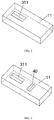
FIG. 3 is a schematic diagram of a position disposed for a strain resistance element in the flexible module structure provided in an embodiment of the present disclosure. -
FIG. 4 is a schematic diagram of the flexible module structure provided inFIG. 3 added with a further strain resistance element. -
FIG. 5 is a schematic diagram of the flexible module structure provided inFIG. 3 added with a further strain resistance element. -
FIG. 6 is a schematic diagram of the flexible module structure provided inFIG. 5 with a changed position of the strain resistance element. -
FIG. 7 is a schematic diagram of the flexible module structure provided inFIG. 5 added with further strain resistance elements. -
FIG. 8 is a schematic diagram of the flexible module structure provided inFIG. 7 with changed positions of the strain resistance elements. -
FIG. 9 is a schematic diagram of the flexible module structure provided inFIG. 7 with changed positions of the strain resistance elements. -
FIG. 10 is a schematic cross-sectional view of a turning mechanism in the flexible module structure provided in an embodiment of the present disclosure. -
FIG. 11 is a flow chart of an operation principle of the flexible module structure provided in an embodiment of the present disclosure. -
FIG. 12 is a schematic diagram of a display apparatus provided in the present disclosure. - In order to make the objective, the technical solutions and the advantages of the present disclosure clearer, embodiments of the present disclosure are described clearly and completely with reference to the drawings for the embodiments in the present disclosure. It is evident that the embodiments described are only some rather than all embodiments of the present disclosure. Based on the embodiments of the present disclosure, all other embodiments obtained by those skilled in the art without any inventive effort fall into the protection scope of the present disclosure.
- For a flexible module structure, there is a problem that during bending and curling of the flexible module structure, it is easy for adjacent layers to separate and debond from each other, thus damaging the flexible module structure.
- Based on the above reason, an embodiment of the present disclosure provides a flexible module structure and a display apparatus. As shown in
FIG. 1 , the flexible module structure includes aflexible panel 10, arotating shaft mechanism 20 and astrain gauge device 30. Theflexible panel 10 includes abendable part 11, therotating shaft mechanism 20 is attached to a surface of thebendable part 11, and thestrain gauge device 30 is at least partially disposed on thebendable part 11. Herein, therotating shaft mechanism 20 includes acontact surface 21 attached to the surface of thebendable part 11. Thestrain gauge device 30 may be embedded in thebendable part 11 as shown inFIG. 1 , or may be attached to the surface of thebendable part 11, or may be partly embedded in thebendable part 11 and partly attached to the surface of thebendable part 11. Specifically, thestrain gauge device 30 may be disposed flexibly according to practice need and is not defined herein. When thebendable part 11 has a buckling deformation, thestrain gauge device 30 acquires a deformation amount of thebendable part 11 and gives a feedback to therotating shaft mechanism 20. Therotating shaft mechanism 20 adjusts its own deformation according to the deformation amount of thebendable part 11 to reduce a distance between a neutral surface and thecontact surface 21 of therotating shaft mechanism 20. In this embodiment, the shorter the distance between the neutral surface and thecontact surface 21 of therotating shaft mechanism 20, the smaller the pressure on thebendable part 11 by therotating shaft mechanism 20. In addition, in this embodiment, when the distance between the neutral surface of therotating shaft mechanism 20 and thecontact surface 21 is reduced to 0, the neutral surface and thecontact surface 21 of therotating shaft mechanism 20 are overlapped. In this case, thecontact surface 21 does not bear a stress and thus does not generate a pressure on thebendable part 11. - When the
rotating shaft mechanism 20 has a buckling deformation with thebendable part 11, a surface at a side of therotating shaft mechanism 20 towards the bending direction is compressed, while a surface at a side of therotating shaft mechanism 20 away from the bending direction is stretched. For therotating shaft mechanism 20, between the compressed surface and stretched surface there is a surface whose length remains unchanged and is defined as a neutral surface. Because the length of the neutral surface remains unchanged, in the case when therotating shaft mechanism 20 has a buckling deformation with thebendable part 11, the neutral surface is neither compressed or stretched and does not generate a bending stress. Parts of therotating shaft mechanism 20 at two sides of the neutral surface may respectively generate a tensile stress and a compressive stress due to the stretch and the compression. A part of therotating shaft mechanism 20, which is closer to the neutral surface, has a smaller deformation and correspondingly generates smaller tensile stress/compressive stress in therotating shaft mechanism 20. - In the flexible module structure provided in this embodiment, the
strain gauge device 30 is disposed on thebendable part 11 of theflexible panel 10. When thebendable part 11 has a deformation, thestrain gauge device 30 acquires the deformation amount of thebendable part 11, and therotating shaft mechanism 20 adjusts the deformation of therotating shaft mechanism 20 according to the acquired deformation amount of thebendable part 11, reducing the distance between the neutral surface and thecontact surface 21 of therotating shaft mechanism 20. A distance between the neutral surface and thecontact surface 21 of therotating shaft mechanism 20 becomes smaller, so that a tensile stress/compressive stress generated at thecontact surface 21 of therotating shaft mechanism 20 is reduced, and a pressure applied on thebendable part 11 by therotating shaft mechanism 20 is also reduced. In this way, the pressure on theflexible panel 10 by therotating shaft mechanism 20 is reduced or even eliminated, thereby achieving the objective of reducing a possibility of separation and debonding between theflexible panel 10 and therotating shaft mechanism 20 during bending process. - In addition, in this embodiment, the
rotating shaft mechanism 20 includes adrive member 22 and an elastic member 23 connected to thedrive member 22. When thebendable part 11 has a buckling deformation, thestrain gauge device 30 acquires a deformation amount of thebendable part 11 and feeds back the acquired deformation amount of thebendable part 11 to thedrive member 22. Thedrive member 22 adjusts the elastic member 23 according to the deformation amount of thebendable part 11 to reduce the distance between the neutral surface and thecontact surface 21 of therotating shaft mechanism 20. For example, when therotating shaft mechanism 20 bends inward, thecontact surface 21 of therotating shaft mechanism 20 is stretched, and thecontact surface 21 is located at a stretched side of the neutral surface of therotating shaft mechanism 20 and generates a tensile stress for recovery to the original state. Therefore, the elastic member 23 is adjusted by thedrive member 22, so that the elastic member 23 generates an elastic force with a direction opposite to a direction of the tensile stress. The elastic force generated by the elastic member 23 offsets part of or all of the tensile stress generated due to deformation of therotating shaft mechanism 20. Because part of or all of the tensile stress is offset by the elastic force generated by the elastic member 23, the tensile stress and the compressive stress generated respectively at two sides of the neutral surface of therotating shaft mechanism 20 are unbalanced and the tensile stress is smaller than the compressive stress. Under action of the compressive stress, the neutral surface moves toward the stretched side in therotating shaft mechanism 20, thereby the distance between the neutral surface and thecontact surface 21 of therotating shaft mechanism 20 is smaller than or equal to a preset threshold. - In this embodiment, the
drive member 22 is a motor and the elastic member 23 is a torsion spring. Cost is low when a drive member is set as a motor and the elastic member is set as a torsion spring. - In this embodiment, the
strain gauge device 30 includes astrain unit 31 and avoltage acquisition unit 32 electrically connected with thestrain unit 31. Herein, a resistance value of thestrain unit 31 changes with its shape. When thebendable part 11 has a buckling deformation, thevoltage acquisition unit 32 acquires a voltage change value in a circuit to acquire a resistance change value of thestrain unit 31 according to the voltage change value, acquires a deformation amount of thestrain unit 31 according to the resistance change value, and acquires the deformation amount of thebendable part 11 according to the deformation amount of thestrain unit 31. Thestrain gauge device 30 is configured to include thestrain unit 31 and thevoltage acquisition unit 32 electrically connected with thestrain unit 31, and the deformation amount of thebendable part 11 is acquired by using a feature that the resistance of thestrain unit 31 changes with the shape of thestrain unit 31; in this way, thestrain gauge device 30 has a simpler structure. - In this embodiment, as shown in
FIG. 2 , thestrain unit 31 at least includes four resistance elements, such as afirst resistance element 311, asecond resistance element 312, athird resistance element 313 and afourth resistance element 314. Herein, thefirst resistance element 311 and thesecond resistance element 312 are connected in series, and thethird resistance element 313 and thefourth resistance element 314 are connected in series, so that a first arm and a second arm connected in series, and a third arm and a fourth arm connected in series in a Wheatstone bridge circuit are formed. One end of thevoltage acquisition unit 32 is electrically connected to a connecting point between thefirst resistance element 311 and thesecond resistance element 312, and the other end of thevoltage acquisition unit 32 is electrically connected to thethird resistance element 313 and thefourth resistance element 314. The four resistance elements includes at least one strain resistance element, and thefourth resistance element 314 is set as the strain resistance element. The above is only one specific example of thestrain unit 31 but does not constitute a limitation. In another embodiment of the present disclosure, the deformation amount of thebendable part 11 may be obtained through another structure, for example, a deformation sensor using another principle, and no more examples therefor are provided herein. - In this embodiment, the
fourth resistance element 314 is a strain gauge, which is a specific example in this embodiment and does not constitute a limitation. In another embodiment of the present disclosure, thefourth resistance element 314 may be another particular element, for which no more examples are provided herein. - In addition, in this embodiment, the
first resistance element 311, thesecond resistance element 312, thethird resistance element 313 and thefourth resistance element 314 are connected to form a Wheatstone bridge circuit, which has a simple connection and may prevent current in the circuit from being too small/large due to too large/small resistance value of thefourth resistance element 314 resulted from deformation of thefourth resistance element 314. In this way, not only the circuit is protected, but accuracy of a voltage change amount acquired by thevoltage acquisition unit 32 is also improved. In the following, for example, taking only one strain resistance element such as thefourth resistance element 314, a calculation for a deformation amount L of thefourth resistance element 314 is described. It is set that resistance values of thefirst resistance element 311, thesecond resistance element 312, thethird resistance element 313 and thefourth resistance element 314 are R1, R2, R3 and R4 respectively, a voltage source EX voltage is VEX, and a voltage value acquired by thevoltage acquisition unit 32 is V0. It is known from a circuit principle of a Wheatstone bridge that:
- When there is no deformation,

fourth resistance element 314. Herein, l is an initial length of thefourth resistance element 314, s is an area of a cross section of thefourth resistance element 314, and ρ is a strain constant of thefourth resistance element 314. - When the
bendable part 11 is bent and deformed, the deformation amount L of thefourth resistance element 314 can be obtained according to
fourth resistance element 314 can be obtained, and thus a product of the length of thebendable part 11 and the ratio is acquired. The length of thebendable part 11 is subtracted from the product to obtain a deformation amount Δl of thebendable part 11. Based on a thickness t of the rotating shaft mechanism, a deformation amount ΔL required to be adjusted of the rotating shaft mechanism can be obtained according to a formula of ΔL=π · t + Δl. - The
first resistance element 311, thesecond resistance element 312, thethird resistance element 313 and thefourth resistance element 314 are connected to form the Wheatstone bridge circuit, which serves as only one particular example of electrical connection between thefirst resistance element 311, thesecond resistance element 312, thethird resistance element 313 and thefourth resistance element 314, and does not constitute a limitation. In another embodiment of the present disclosure, there may be another circuit connection structure, for which no more example is provided herein. - In this embodiment, there is one strain resistance element. As shown in
FIG. 3 , for example, taking the strain resistance element as thefirst resistance element 311, the firststrain resistance element 311 is disposed in a one-fourth bridging manner. By using one strain resistance element, cost may be reduced. In addition, one strain resistance element is disposed in a one-fourth bridging manner, which has a relatively simple connection relationship, and can effectively simplify a producing process. - As shown in
FIG. 4 , in this embodiment, in order to eliminate the influence of temperature on the resistance value of the strain resistance element, astrain resistance element 40 of the same specification may be set on theflexible panel 10 for comparison, so as to eliminate the influence of temperature on the resistance value of the strain resistance element, and to improve measurement accuracy of the deformation amount of thebendable part 11. - In addition, in this embodiment, the
flexible panel 10 is a flexible display panel including a pixel unit, and thestrain gauge device 30 is electrically connected to a drive circuit of the pixel unit. When theflexible panel 10 is a flexible display panel, thestrain gauge device 30 is configured to electrically connect to drive circuit of the pixel unit, and thestrain gauge device 30 is powered directly through a pixel drive circuit of the flexible display panel. Therefore, it is not necessary to provide a additional power supply circuit for thestrain gauge device 30, effectively simplifying aflexible module structure 100 and reducing preparation cost and processing requirement to the flexible module structure. - An embodiment of the present disclosure further provides a flexible module structure, in which the
strain unit 31 includes two strain resistance elements, such as thefirst resistance element 311 and thesecond resistance element 312. - As shown in
FIG. 5 , it is set that the two strain resistance elements are thefirst resistance element 311 and thesecond resistance element 312 disposed in a half bridging manner and in the same plane. - Further, as shown in
FIG. 6 , thefirst resistance element 311 and thesecond resistance element 312 are oppositely disposed in two planes. It may be flexibly selected according to a practical need as to whether to dispose thefirst resistance element 311 and the second resistance element 3121 in the same plane or in two planes, but both can achieve the technical effect of measuring the deformation amount of thebendable part 11. - The
first resistance element 311 and thesecond resistance element 312 are disposed on two arms connected in series of the Wheatstone bridge circuit, which is only one example for this embodiment but does not constitute a limitation. In another embodiment of the present disclosure, there may be another disposing manner. For example, thefirst resistance element 311 and thesecond resistance element 312 are disposed on two arms connected in parallel of the Wheatstone bridge circuit, and no more example is provided herein. - Because only an installation manner of the strain gauge device in the embodiment is changed, the present embodiment has the same technical effect for other unchanged parts, which is not repeated. In addition, the two strain resistance units of the
first resistance element 311 and thesecond resistance element 312 are provided and can be compared to perform effective temperature compensation, thereby improving accuracy of a measurement result. In addition, thefirst resistance element 311 and thesecond resistance element 312 are disposed in a half bridging manner, further improving accuracy of the measurement result. - An embodiment of the present disclosure further relates to a flexible module structure. Herein, the
first resistance element 311, thesecond resistance element 312, thethird resistance element 313 and thefourth resistance element 314 are all strain resistance elements. - The four strain resistance elements are disposed in a full bridging manner.
- The
first resistance element 311, thesecond resistance element 312, thethird resistance element 313 and thefourth resistance element 314 are disposed oppositely in a two-by-two manner. - As shown in
FIG. 7 , thefirst resistance element 311 and thethird resistance element 313 are disposed in the same plane, and thefirst resistance element 311 and thefourth resistance element 314 extend in the same direction; thesecond resistance element 312 and thefourth resistance element 314 are disposed in the same plane, and thesecond resistance element 312 and thefourth resistance element 314 extend in the same direction; thefirst resistance element 311 and thesecond resistance element 312 are disposed opposite to each other, and thethird resistance element 313 and thefourth resistance element 314 are disposed opposite to each other. Alternatively, as shown inFIG. 8 , thefirst resistance element 311 and thefourth resistance element 314 are disposed in the same plane and extend in different directions; thesecond resistance element 312 and thethird resistance element 313 are disposed in the same plane and extend in different directions; thefirst resistance element 311 and thesecond resistance element 312 are disposed opposite to each other, and thethird resistance element 313 and thefourth resistance element 314 are disposed opposite to each other. Alternatively, as shown inFIG. 9 , thefirst resistance element 311 and thesecond resistance element 312 are disposed in the same plane and extend in different directions, and thethird resistance element 313 and thefourth resistance element 314 are disposed in the same plane and extend in different directions; thefirst resistance element 311 and thethird resistance element 313 are disposed opposite to each other, and thesecond resistance element 312 and thefourth resistance element 314 are disposed opposite to each other. - The
first resistance element 311, thesecond resistance element 312, thethird resistance element 313 and thefourth resistance element 314 are disposed oppositely in a two-by-two manner, which is only one example for this embodiment but does not constitute a limitation. In another embodiment of the present disclosure, there may be another disposing manner for which no more example is provided herein. - Because only an installation manner of the strain gauge device in the embodiment is changed, the present embodiment has the same technical effect for other unchanged parts, which is not repeated. In addition, in the third embodiment in the present disclosure, the four strain resistance units are disposed and can be compared to perform effective temperature compensation, thereby improving accuracy of the measurement result. In addition, the four strain resistance elements are disposed in a full bridging manner, further improving accuracy of the measurement result as compared with the one fourth bridging manner in an embodiment and the half bridging manner in the second embodiment.
- In the following, properties of bridging manners of the
strain gauge device 30 related to the above embodiments are described with reference to Table One, which may be chosen to use according to practical needs by those skilled in the art. The properties of the bridging manners are as shown in the following table. Herein Y denotes having this property and N denotes not having this property.Table One FIG. 3 FIG. 4 FIG. 5 FIG. 6 FIG. 7 FIG. 8 FIG. 9 Axial strain Y Y Y N N N Y Bending strain Y Y Y Y Y Y N Transverse sensitivity compensation N N Y N N Y Y Temperature compensation N Y Y Y Y Y Y Installation position Located at a single side of a Wheatstone bridge Located at a single side of a Wheatstone bridge Located at a single side of a Wheatstone bridge Located at two opposite sides of a Wheatstone bridge Located at two opposite sides of a Wheatstone bridge Located at two opposite sides of a Wheatstone bridge Located at two opposite sides of a Wheatstone bridge Wires provided 2 or 3 3 3 3 4 4 4 - As shown in Table One, the bridging manner shown in
FIG. 3 has an axial strain and a bending strain, installation position thereof being single-sided, and wires provided being 2 or 3. The bridging manner shown inFIG. 4 has an axial strain and a bending strain, temperature compensation, installation position thereof being single-sided, and wires provided being 3. The bridging manner shown inFIG. 5 has an axial strain and a bending strain, temperature compensation and transverse sensitivity compensation, installation position thereof being single-sided, and wires provided being 3. The bridging manner shown inFIG. 6 has a bending strain, temperature compensation, installation position thereof being two-opposite-sided, and wires provided being 3. The bridging manner shown inFIG. 7 has a bending strain, temperature compensation, installation position thereof being two-opposite-sided, and wires provided being 4. The bridging manner shown inFIG. 8 has a bending strain, temperature compensation and transverse sensitivity compensation, installation position thereof being two-opposite-sided, and wires provided being 4. The bridging manner shown inFIG. 9 has an axial strain, temperature compensation and transverse sensitivity compensation, installation position thereof being two-opposite-sided, and wires provided being 4. - An embodiment of the present disclosure further relates to a flexible module structure. As shown in
FIG. 10 , therotating shaft mechanism 20 includes astrain surface 24 disposed opposite to thecontact surface 21, and therotating shaft mechanism 20 includes arecess 25 protruding from thestrain surface 24 towards thecontact surface 21. - A shape of the
recess 25 may be any shape such as a square or a cone or another shape not listed herein. - Further, in this embodiment, the
recess 25 may be a groove parallel to a bending axis direction of thebendable part 11. In particular, the bending axis direction may be an extending direction of a bend axis when thebendable part 11 bends. - In the case that all technical effects of the above embodiments are maintained and
recesses 25 protruding from thestrain surface 24 towards thecontact surface 21 are disposed on therotating shaft mechanism 20, when therotating shaft mechanism 20 has a buckling deformation, therecesses 25 can effectively reduce a stress of thestrain surface 24, so that the neutral surface of therotating shaft mechanism 20 gets closer to thecontact surface 21. - In the following, the operation principle of the flexible module structure provided in the embodiments of the present disclosure is described. The following is only a description on flows of detailed operation principle of components in the flexible module structure provided in the embodiments of the present disclosure, and does not constitute a limitation. As shown in
FIG. 11 , the following steps are included: - S101: the
strain gauge device 30 acquires a deformation amount of thebendable part 11. - A particular implementation for the
strain gauge device 30 to acquire the deformation amount of thebendable part 11 is already described in the embodiments and is not repeated. - S102: the
strain gauge device 30 transmits the acquired deformation amount of thebendable part 11 to thedrive member 22. - S103: the
drive member 22 adjusts the elastic member 23 according to received deformation amount of thebendable part 11, to enable the distance between the neutral surface and thecontact surface 21 of therotating shaft mechanism 20 to be smaller than a preset threshold. - A particular implementation, in which the
drive member 22 adjusts the elastic member 23 according to the received deformation amount of thebendable part 11 to enable the distance between the neutral surface and thecontact surface 21 of therotating shaft mechanism 20 to be smaller than a preset threshold, is already described in the embodiments and is not repeated. - An embodiment of the present disclosure relates to a display apparatus, as shown in
FIG. 12 , including: theflexible module structure 100 provided in the above, afilm packaging layer 200 disposed on theflexible module structure 100 and alight transmitting layer 300 disposed on thefilm packaging layer 200. - Further, a
polarizer 400 may be disposed on thefilm packaging layer 200. - Those skilled in the art may appreciate that the above embodiments are particular embodiments for implementing the present disclosure. In practice, however, the embodiments may change in terms of form and details, for example, by combining two or more embodiments, without departing from the spirit and scope of the present disclosure.
Claims (17)
- A flexible module structure, comprising:a flexible panel, having a bendable part;a rotating shaft mechanism, attached to a surface of the bendable part and comprising a contact surface attached to the surface of the bendable part; anda strain gauge device, at least partially disposed on the bendable part;wherein, when the bendable part has a buckling deformation, the strain gauge device is configured to acquire a deformation amount of the bendable part and give a feedback to the rotating shaft mechanism, and the rotating shaft mechanism is configured to reduce a distance between a neutral surface and the contact surface of the rotating shaft mechanism according to the deformation amount.
- The flexible module structure according to claim 1, wherein the strain gauge device comprises a strain unit and a voltage acquisition unit electrically connected with the strain unit,
when the bendable part has a buckling deformation, the voltage acquisition unit is configured to acquire a voltage change value to acquire a resistance change value of the strain unit according to the voltage change value and acquire the deformation amount according to the resistance change value. - The flexible module structure according to claim 2, wherein the strain unit comprises at least four resistance elements that comprise at least one strain resistance element.
- The flexible module structure according to claim 3, wherein the four resistance elements are connected to form a Wheatstone bridge circuit.
- The flexible module structure according to claim 4, wherein the Wheatstone bridge circuit comprises a first arm and a second arm connected in series and a third arm and a fourth arm connected in series, one end of the voltage acquisition unit is electrically connected to a connecting point between the first arm and the second arm, and the other end of the voltage acquisition unit is electrically connected to a connecting point between the third arm and the fourth arm.
- The flexible module structure according to claim 3, wherein the at least one strain resistance element comprises one strain resistance element disposed in a one-fourth bridging manner.
- The flexible module structure according to claim 3, wherein the at least one strain resistance element comprises two strain resistance elements disposed in a half bridging manner.
- The flexible module structure according to claim 7, wherein the two strain resistance elements are disposed at two arms connected in series of a Wheatstone bridge.
- The flexible module structure according to claim 7, wherein the two strain resistance elements are disposed on two opposite surfaces of the bendable part.
- The flexible module structure according to claim 3, wherein the at least one strain resistance element comprises four strain resistance elements disposed in a full bridging manner.
- The flexible module structure according to claim 10, wherein two of the four strain resistance elements are disposed on a surface of the bendable part and the other two of the four strain resistance elements are correspondingly disposed on an opposite surface of the bendable part.
- The flexible module structure according to any one of claims 1 to 11, wherein the flexible panel is a flexible display panel comprising a pixel unit, and the strain gauge device is electrically connected to a drive circuit of the pixel unit.
- The flexible module structure according to claim 1, wherein the rotating shaft mechanism comprises a drive member and an elastic member connected to the drive member, and the drive member is configured to adjust the elastic member according to the deformation amount to reduce a distance between the neutral surface and the contact surface of the rotating shaft mechanism.
- The flexible module structure according to claim 13, wherein the drive member is a motor, and the elastic member is a torsion spring.
- The flexible module structure according to claim 1, wherein the rotating shaft mechanism comprises a strain surface disposed opposite to the contact surface, and the rotating shaft mechanism comprises a recess protruding from the strain surface towards the contact surface.
- The flexible module structure according to claim 15, wherein the recess is a groove parallel to a bending axis direction of the bendable part.
- A display apparatus, comprising:the flexible module structure according to any one of claims 1 to 16;a film packaging layer disposed on the flexible module structure; anda light transmitting layer disposed on the film packaging layer.
Applications Claiming Priority (2)
| Application Number | Priority Date | Filing Date | Title |
|---|---|---|---|
| CN201910323557.1A CN110060573B (en) | 2019-04-22 | 2019-04-22 | Flexible module structure and display device |
| PCT/CN2019/113462 WO2020215639A1 (en) | 2019-04-22 | 2019-10-25 | Flexible module structure and display apparatus |
Publications (2)
| Publication Number | Publication Date |
|---|---|
| EP3896680A1 true EP3896680A1 (en) | 2021-10-20 |
| EP3896680A4 EP3896680A4 (en) | 2022-02-23 |
Family
ID=67320054
Family Applications (1)
| Application Number | Title | Priority Date | Filing Date |
|---|---|---|---|
| EP19926512.5A Pending EP3896680A4 (en) | 2019-04-22 | 2019-10-25 | FLEXIBLE MODULAR STRUCTURE AND DISPLAY DEVICE |
Country Status (7)
| Country | Link |
|---|---|
| US (1) | US20210270684A1 (en) |
| EP (1) | EP3896680A4 (en) |
| JP (1) | JP7149429B2 (en) |
| KR (1) | KR102520525B1 (en) |
| CN (1) | CN110060573B (en) |
| TW (1) | TWI725622B (en) |
| WO (1) | WO2020215639A1 (en) |
Families Citing this family (6)
| Publication number | Priority date | Publication date | Assignee | Title |
|---|---|---|---|---|
| CN110060573B (en) * | 2019-04-22 | 2020-12-29 | 昆山国显光电有限公司 | Flexible module structure and display device |
| CN110726363B (en) | 2019-10-14 | 2021-11-02 | 武汉华星光电半导体显示技术有限公司 | Display device and manufacturing method thereof |
| CN112783272A (en) * | 2021-01-27 | 2021-05-11 | 维沃移动通信有限公司 | Detection method and device |
| CN114038331A (en) * | 2021-11-30 | 2022-02-11 | 长沙惠科光电有限公司 | Display panels and display devices |
| CN116935742B (en) * | 2022-03-30 | 2025-11-07 | 华为技术有限公司 | Folding screen auxiliary device, manufacturing method thereof and related equipment |
| CN118968886B (en) * | 2024-08-30 | 2025-11-04 | 武汉天马微电子有限公司上海分公司 | A display module and electronic device |
Family Cites Families (26)
| Publication number | Priority date | Publication date | Assignee | Title |
|---|---|---|---|---|
| KR101879615B1 (en) * | 2011-11-23 | 2018-07-19 | 삼성전자주식회사 | Display device and control method thereof |
| KR101903053B1 (en) * | 2012-07-10 | 2018-11-23 | 삼성디스플레이 주식회사 | Flexible display device |
| CN104756176B (en) * | 2012-10-25 | 2017-12-08 | Lg电子株式会社 | Display device |
| KR102118403B1 (en) * | 2013-05-08 | 2020-06-03 | 삼성전자주식회사 | Flexible device, apparatus, method and computer readable recording medium for sensing the shape of the flexible device |
| US9886084B2 (en) * | 2014-11-11 | 2018-02-06 | Intel Corporation | User input via elastic deformation of a material |
| TWI623855B (en) * | 2014-11-13 | 2018-05-11 | Method for controlling operation of flexible display device | |
| TWI550850B (en) * | 2014-11-19 | 2016-09-21 | 財團法人工業技術研究院 | Flexible electronic device |
| US9741772B2 (en) * | 2014-12-26 | 2017-08-22 | Lg Display Co., Ltd. | Display device comprising bending sensor |
| KR20160089164A (en) * | 2015-01-19 | 2016-07-27 | 삼성전자주식회사 | Flexible device and method for controlling shape of display thereof |
| KR102375085B1 (en) * | 2015-04-30 | 2022-03-17 | 삼성디스플레이 주식회사 | Display device |
| KR102396458B1 (en) * | 2015-08-26 | 2022-05-10 | 엘지디스플레이 주식회사 | Flexible display device |
| US9960375B2 (en) * | 2015-08-31 | 2018-05-01 | Lg Display Co., Ltd. | Organic light-emitting display device |
| CN106773185B (en) * | 2017-02-06 | 2024-05-03 | 东旭(昆山)显示材料有限公司 | Gap adjusting device, roller gap adjusting method and roller deformation detecting method |
| CN106910427B (en) * | 2017-02-23 | 2019-11-22 | 武汉华星光电技术有限公司 | A kind of open and flat method of display and its flexible display screen |
| CN206756350U (en) * | 2017-03-15 | 2017-12-15 | 北京中航兴盛测控技术有限公司 | Thin film strain formula torque sensor |
| CN106910842B (en) * | 2017-04-17 | 2019-01-15 | 京东方科技集团股份有限公司 | A kind of encapsulating structure, flexible display substrates and flexible display apparatus |
| TWI622832B (en) * | 2017-05-23 | 2018-05-01 | 元太科技工業股份有限公司 | Carrier apparatus and display |
| US10649267B2 (en) * | 2017-07-19 | 2020-05-12 | Innolux Corporation | Display device and manufacturing method thereof |
| CN107195253B (en) * | 2017-07-26 | 2020-08-25 | 武汉天马微电子有限公司 | Foldable flexible display device |
| CN108447433B (en) * | 2018-02-28 | 2024-07-02 | 厦门天马微电子有限公司 | Curved surface display panel and stress detection and voltage regulation method thereof |
| CN108447401B (en) * | 2018-03-28 | 2020-06-05 | 武汉华星光电技术有限公司 | Flexible display device and deformation compensation method of flexible display screen |
| CN108766246A (en) * | 2018-07-18 | 2018-11-06 | 昆山国显光电有限公司 | Display panel and display device |
| CN208737802U (en) * | 2018-08-21 | 2019-04-12 | 深圳市柔宇科技有限公司 | Electronic device and flexible display device thereof |
| CN109148534B (en) * | 2018-08-21 | 2021-01-15 | 武汉华星光电半导体显示技术有限公司 | Display panel and electronic device |
| CN109584725B (en) * | 2019-01-02 | 2021-10-01 | 上海天马有机发光显示技术有限公司 | A display panel and display device |
| CN110060573B (en) * | 2019-04-22 | 2020-12-29 | 昆山国显光电有限公司 | Flexible module structure and display device |
-
2019
- 2019-04-22 CN CN201910323557.1A patent/CN110060573B/en active Active
- 2019-10-25 JP JP2021540433A patent/JP7149429B2/en active Active
- 2019-10-25 EP EP19926512.5A patent/EP3896680A4/en active Pending
- 2019-10-25 WO PCT/CN2019/113462 patent/WO2020215639A1/en not_active Ceased
- 2019-10-25 KR KR1020217020658A patent/KR102520525B1/en active Active
- 2019-11-15 TW TW108141527A patent/TWI725622B/en active
-
2021
- 2021-05-07 US US17/314,365 patent/US20210270684A1/en not_active Abandoned
Also Published As
| Publication number | Publication date |
|---|---|
| JP2022518199A (en) | 2022-03-14 |
| CN110060573A (en) | 2019-07-26 |
| TW202013327A (en) | 2020-04-01 |
| TWI725622B (en) | 2021-04-21 |
| KR102520525B1 (en) | 2023-04-12 |
| EP3896680A4 (en) | 2022-02-23 |
| KR20210091329A (en) | 2021-07-21 |
| US20210270684A1 (en) | 2021-09-02 |
| CN110060573B (en) | 2020-12-29 |
| WO2020215639A1 (en) | 2020-10-29 |
| JP7149429B2 (en) | 2022-10-06 |
Similar Documents
| Publication | Publication Date | Title |
|---|---|---|
| US20210270684A1 (en) | Flexible module and display device | |
| KR101673884B1 (en) | Pressure detector and touch panel provided with pressure detector | |
| TWI238686B (en) | Flexible substrate, LCD module using same, and manufacturing method of same | |
| KR20150058256A (en) | Capacitance-type sensor sheet, method for manufacturing capacitance-type sensor sheet, and sensor | |
| KR20030088137A (en) | Tangential force control in a touch location device | |
| KR101533883B1 (en) | Polarizer plate and display device having the same | |
| CN210984090U (en) | display device | |
| KR102398552B1 (en) | Flexible display device having bending sensing device | |
| CN104952386B (en) | Display device, gamma compensated device and gamma compensated method | |
| CN101910812A (en) | load cell | |
| CN106486039A (en) | There are the flexible display apparatus of bending sensing device further | |
| CN1364244A (en) | Twisted nematic liquid crystal display device with operating voltage temperature compensation device | |
| US7497126B2 (en) | Pressure sensor | |
| CN112284580B (en) | Pressure sensor based on mechanical metamaterial structure | |
| TW201706783A (en) | Display panel with embedded force sensor | |
| WO2018008572A1 (en) | Piezoelectric sensor | |
| KR20150055888A (en) | Display apparatus | |
| US20190095024A1 (en) | Pressure sensing device and electronic apparatus having same | |
| US20200004082A1 (en) | Liquid crystal display device | |
| CN113920907B (en) | Display device and driving compensation method thereof | |
| CN105242415A (en) | Probe substrate and display panel detection device | |
| CN116929632A (en) | Two-direction force loading device for calibrating multidimensional force sensor | |
| CN104654933B (en) | A kind of electric servomechanism and adjustment method thereof | |
| CN116301205A (en) | Electronic equipment | |
| CN113031300A (en) | Display device and control method thereof |
Legal Events
| Date | Code | Title | Description |
|---|---|---|---|
| STAA | Information on the status of an ep patent application or granted ep patent |
Free format text: STATUS: THE INTERNATIONAL PUBLICATION HAS BEEN MADE |
|
| PUAI | Public reference made under article 153(3) epc to a published international application that has entered the european phase |
Free format text: ORIGINAL CODE: 0009012 |
|
| STAA | Information on the status of an ep patent application or granted ep patent |
Free format text: STATUS: REQUEST FOR EXAMINATION WAS MADE |
|
| 17P | Request for examination filed |
Effective date: 20210715 |
|
| AK | Designated contracting states |
Kind code of ref document: A1 Designated state(s): AL AT BE BG CH CY CZ DE DK EE ES FI FR GB GR HR HU IE IS IT LI LT LU LV MC MK MT NL NO PL PT RO RS SE SI SK SM TR |
|
| A4 | Supplementary search report drawn up and despatched |
Effective date: 20220125 |
|
| RIC1 | Information provided on ipc code assigned before grant |
Ipc: G01L 1/22 20060101ALI20220119BHEP Ipc: H01L 51/52 20060101ALI20220119BHEP Ipc: G09F 9/30 20060101AFI20220119BHEP |
|
| DAV | Request for validation of the european patent (deleted) | ||
| DAX | Request for extension of the european patent (deleted) | ||
| STAA | Information on the status of an ep patent application or granted ep patent |
Free format text: STATUS: EXAMINATION IS IN PROGRESS |
|
| 17Q | First examination report despatched |
Effective date: 20250130 |