EP3896366A1 - Verfahren und vorrichtung für rotationsdrehzahlschwankung eines verdichters - Google Patents
Verfahren und vorrichtung für rotationsdrehzahlschwankung eines verdichters Download PDFInfo
- Publication number
- EP3896366A1 EP3896366A1 EP19896103.9A EP19896103A EP3896366A1 EP 3896366 A1 EP3896366 A1 EP 3896366A1 EP 19896103 A EP19896103 A EP 19896103A EP 3896366 A1 EP3896366 A1 EP 3896366A1
- Authority
- EP
- European Patent Office
- Prior art keywords
- shaft error
- angular velocity
- harmonic
- axis component
- corrected
- Prior art date
- Legal status (The legal status is an assumption and is not a legal conclusion. Google has not performed a legal analysis and makes no representation as to the accuracy of the status listed.)
- Granted
Links
Images


Classifications
-
- F—MECHANICAL ENGINEERING; LIGHTING; HEATING; WEAPONS; BLASTING
- F04—POSITIVE - DISPLACEMENT MACHINES FOR LIQUIDS; PUMPS FOR LIQUIDS OR ELASTIC FLUIDS
- F04C—ROTARY-PISTON, OR OSCILLATING-PISTON, POSITIVE-DISPLACEMENT MACHINES FOR LIQUIDS; ROTARY-PISTON, OR OSCILLATING-PISTON, POSITIVE-DISPLACEMENT PUMPS
- F04C29/00—Component parts, details or accessories of pumps or pumping installations, not provided for in groups F04C18/00 - F04C28/00
- F04C29/0021—Systems for the equilibration of forces acting on the pump
- F04C29/0035—Equalization of pressure pulses
-
- F—MECHANICAL ENGINEERING; LIGHTING; HEATING; WEAPONS; BLASTING
- F04—POSITIVE - DISPLACEMENT MACHINES FOR LIQUIDS; PUMPS FOR LIQUIDS OR ELASTIC FLUIDS
- F04C—ROTARY-PISTON, OR OSCILLATING-PISTON, POSITIVE-DISPLACEMENT MACHINES FOR LIQUIDS; ROTARY-PISTON, OR OSCILLATING-PISTON, POSITIVE-DISPLACEMENT PUMPS
- F04C28/00—Control of, monitoring of, or safety arrangements for, pumps or pumping installations specially adapted for elastic fluids
- F04C28/08—Control of, monitoring of, or safety arrangements for, pumps or pumping installations specially adapted for elastic fluids characterised by varying the rotational speed
-
- F—MECHANICAL ENGINEERING; LIGHTING; HEATING; WEAPONS; BLASTING
- F04—POSITIVE - DISPLACEMENT MACHINES FOR LIQUIDS; PUMPS FOR LIQUIDS OR ELASTIC FLUIDS
- F04C—ROTARY-PISTON, OR OSCILLATING-PISTON, POSITIVE-DISPLACEMENT MACHINES FOR LIQUIDS; ROTARY-PISTON, OR OSCILLATING-PISTON, POSITIVE-DISPLACEMENT PUMPS
- F04C28/00—Control of, monitoring of, or safety arrangements for, pumps or pumping installations specially adapted for elastic fluids
- F04C28/28—Safety arrangements; Monitoring
-
- F—MECHANICAL ENGINEERING; LIGHTING; HEATING; WEAPONS; BLASTING
- F04—POSITIVE - DISPLACEMENT MACHINES FOR LIQUIDS; PUMPS FOR LIQUIDS OR ELASTIC FLUIDS
- F04C—ROTARY-PISTON, OR OSCILLATING-PISTON, POSITIVE-DISPLACEMENT MACHINES FOR LIQUIDS; ROTARY-PISTON, OR OSCILLATING-PISTON, POSITIVE-DISPLACEMENT PUMPS
- F04C29/00—Component parts, details or accessories of pumps or pumping installations, not provided for in groups F04C18/00 - F04C28/00
- F04C29/0042—Driving elements, brakes, couplings, transmissions specially adapted for pumps
- F04C29/0085—Prime movers
-
- H—ELECTRICITY
- H02—GENERATION; CONVERSION OR DISTRIBUTION OF ELECTRIC POWER
- H02P—CONTROL OR REGULATION OF ELECTRIC MOTORS, ELECTRIC GENERATORS OR DYNAMO-ELECTRIC CONVERTERS; CONTROLLING TRANSFORMERS, REACTORS OR CHOKE COILS
- H02P6/00—Arrangements for controlling synchronous motors or other dynamo-electric motors using electronic commutation dependent on the rotor position; Electronic commutators therefor
- H02P6/08—Arrangements for controlling the speed or torque of a single motor
-
- H—ELECTRICITY
- H02—GENERATION; CONVERSION OR DISTRIBUTION OF ELECTRIC POWER
- H02P—CONTROL OR REGULATION OF ELECTRIC MOTORS, ELECTRIC GENERATORS OR DYNAMO-ELECTRIC CONVERTERS; CONTROLLING TRANSFORMERS, REACTORS OR CHOKE COILS
- H02P6/00—Arrangements for controlling synchronous motors or other dynamo-electric motors using electronic commutation dependent on the rotor position; Electronic commutators therefor
- H02P6/14—Electronic commutators
- H02P6/16—Circuit arrangements for detecting position
- H02P6/18—Circuit arrangements for detecting position without separate position detecting elements
-
- F—MECHANICAL ENGINEERING; LIGHTING; HEATING; WEAPONS; BLASTING
- F04—POSITIVE - DISPLACEMENT MACHINES FOR LIQUIDS; PUMPS FOR LIQUIDS OR ELASTIC FLUIDS
- F04C—ROTARY-PISTON, OR OSCILLATING-PISTON, POSITIVE-DISPLACEMENT MACHINES FOR LIQUIDS; ROTARY-PISTON, OR OSCILLATING-PISTON, POSITIVE-DISPLACEMENT PUMPS
- F04C2270/00—Control; Monitoring or safety arrangements
- F04C2270/60—Prime mover parameters
- F04C2270/605—Controlled or regulated
-
- F—MECHANICAL ENGINEERING; LIGHTING; HEATING; WEAPONS; BLASTING
- F04—POSITIVE - DISPLACEMENT MACHINES FOR LIQUIDS; PUMPS FOR LIQUIDS OR ELASTIC FLUIDS
- F04C—ROTARY-PISTON, OR OSCILLATING-PISTON, POSITIVE-DISPLACEMENT MACHINES FOR LIQUIDS; ROTARY-PISTON, OR OSCILLATING-PISTON, POSITIVE-DISPLACEMENT PUMPS
- F04C2270/00—Control; Monitoring or safety arrangements
- F04C2270/80—Diagnostics
-
- F—MECHANICAL ENGINEERING; LIGHTING; HEATING; WEAPONS; BLASTING
- F04—POSITIVE - DISPLACEMENT MACHINES FOR LIQUIDS; PUMPS FOR LIQUIDS OR ELASTIC FLUIDS
- F04C—ROTARY-PISTON, OR OSCILLATING-PISTON, POSITIVE-DISPLACEMENT MACHINES FOR LIQUIDS; ROTARY-PISTON, OR OSCILLATING-PISTON, POSITIVE-DISPLACEMENT PUMPS
- F04C2270/00—Control; Monitoring or safety arrangements
- F04C2270/86—Detection
Definitions
- the present invention belongs to the field of motor control technology, specifically, it relates to compressor control technology, and more specifically, it relates to a method and a device for suppressing fluctuations in compressor speed.
- the prior art provides methods for suppressing fluctuation in compressor speed but effects are far from satisfactory, practically the problem of fluctuation in compressor speed is not properly solved.
- the object of the present invention is to provide a method and device for suppressing fluctuation in compressor speed, and improve the effectiveness of the suppression of the fluctuation.
- a method for suppressing fluctuations in compressor speed comprises the following steps:
- the step to filter the shaft error ⁇ to obtain a corrected shaft error ⁇ ' in which at least a part of fluctuation on the shaft error is eliminated includes: filtering the shaft error ⁇ to at least remove a d-axis component of and a q-axis component of the first harmonic so as to realize the filtering of the first harmonic component of ⁇ and to obtain the corrected shaft error ⁇ ' in which at least the first harmonic component is removed.
- the step to filter the shaft error ⁇ to obtain a corrected shaft error ⁇ ' in which at least a part of fluctuation on the shaft error is eliminated includes: filtering the shaft error ⁇ to remove a d-axis component of and a q-axis component of the second harmonic so as to realize the filtering of the first and second harmonic component of ⁇ and to obtain the corrected shaft error ⁇ ' in which the first and second harmonic components are removed.
- the step that a d-axis component and a q-axis component of one or more harmonics are eliminated to complete a filtering process of the shaft error ⁇ includes:
- a device for suppressing fluctuation in compressor speed includes:
- the angular velocity compensation amount acquisition unit configured to filter the shaft error ⁇ to obtain a corrected shaft error ⁇ ' in which at least a part of shaft error fluctuation is eliminated, further includes: filtering the shaft error ⁇ to at least remove a d-axis component of and a q-axis component of the first harmonic so as to realize the filtering of the first harmonic component of ⁇ and to obtain the corrected shaft error ⁇ ' in which at least the first harmonic component is removed.
- the angular velocity compensation amount acquisition unit configured to filter the shaft error ⁇ to obtain a corrected shaft error ⁇ ' in which at least a part of shaft error fluctuation is eliminated, further includes: filtering the shaft error ⁇ to remove a d-axis component of and a q-axis component of the second harmonic so as to realize the filtering of the first and second harmonic component of ⁇ and to obtain the corrected shaft error ⁇ ' in which the first and second harmonic components are removed.
- a d-axis component and a q-axis component of one or more harmonics are eliminated to complete a filtering process of the shaft error ⁇ includes:
- the advantages and positive effects of the present invention are: with the method and device for suppressing fluctuation in compressor speed provided by the present invention, fluctuation on the shaft error ⁇ which reflects the deviation between the actual position and the estimated position of the compressor rotor is eliminated, and then the angular velocity compensation amount, which corresponds to the corrected shaft error in which at least part of fluctuation is filtered out, is added to the output angular velocity of the phase-locked loop regulator to obtain the compensated angular velocity output, and then the real-time angular velocity of the compressor is corrected according to the compensated angular velocity output; when the compressor is controlled by the corrected real-time angular velocity, it could make a variation from the target speed and a phase close to the variation and phase of the actual speed, so the operation of the compressor tends to be stable.
- a phase compensation angle is used to adjust the phase of the harmonic components when extracting the harmonic components in the shaft error ⁇ so phase characteristics of the phase-locked loop are changed, which can improve the fluctuation suppression effect during the compressor operation in the full frequency domain, thereby improving the stability of the overall frequency domain operation.
- Fig. 1 is a flowchart of a method for suppressing fluctuations in compressor speed provided according to one aspect of the present invention
- Fig.2 is a block diagram.
- the method for suppressing fluctuations in compressor speed comprising the following steps: Step 11, obtaining a shaft error ⁇ which reflects a deviation of an actual position of a compressor rotor from an estimated position of a compressor rotor.
- Compressor control methods involve a phase-locked loop (PLL) technology to lock a phase of the compressor at a target phase.
- PLL phase-locked loop
- a control block diagram of PLL is shown in Fig.2 .
- a typical phase-locked loop (PLL) of compressor in the prior art comprise a phase-locked loop regulator which is preferably a proportional integral regulator shown as blocks marked by K P_PLL and K I_PLI / S in Fig.2 , wherein K P_PLL and K I_PL are closed-loop gain parameters of the phase-locked loop.
- the shaft error ⁇ is used as a part of an input of the phase-locked loop regulator.
- a difference between the shaft error ⁇ and a target angle fluctuation amount (as an example the target angle fluctuation amount is set as 0 in Fig. 2 ) is input to the phase-locked loop regulator and the phase-locked loop regulator outputs an angular velocity A ⁇ _PLL which is used by the phase-locked loop to control a real-time angular velocity ⁇ 1 for the compressor, and specifically to control a position of the compressor rotor by the real-time angular velocity ⁇ 1.
- V d ⁇ is a given value of a d-axis voltage of the compressor
- V q ⁇ is a given value of q-axis voltage of the compressor
- I d is a real-time d-axis current of the compressor
- Iq is a real-time q-axis current of the compressor
- r * is a motor resistance of the compressor
- L* q is a q-axis inductance of the compressor
- ⁇ 1 is a real-time angular frequency of the compressor
- Step 12 Filtering the shaft error ⁇ to obtain a corrected shaft error ⁇ ' in which at least a part of shaft error fluctuation is eliminated.
- the shaft error Due to the fact that the shaft error is used as a part of the input of the phase-locked loop, it definitely has influence on the real-time angular velocity of the compressor output by the phase-locked loop. If the shaft error is subject to a severe fluctuation, the real-time angular velocity output by the phase-locked loop will be in variation, which further results in a problem that the rotor could not able to be held at the target phase stably which further leads to failures of the compressor such as over-current or out-of-step.
- Step 11 the step to filter the shaft error ⁇ is disclosed so as to obtain a corrected shaft error ⁇ ' in which at least a part of shaft error fluctuation is eliminated.
- the filtering of the shaft error ⁇ includes: Firstly, the shaft error ⁇ is expanded by Fourier series so as to obtain a function expression of the shaft error with respect to a mechanical angle ⁇ m.
- d-axis components and q-axis components of one or more harmonics are eliminated to finish a filtering process of the shaft error ⁇ .
- Step 13 Obtaining an angular velocity compensation amount P_out according to the corrected shaft error ⁇ '.
- This step could be implemented by means disclosed in the prior art which are utilized to calculate an angular velocity according to an angle.
- a preferred processing method could refer to a description as follows.
- Step 12 and Step 13 are shown in the control block diagram of Fig. 2 , and it is to adopt a fluctuation filtering algorithm on the shaft error ⁇ to obtain the angular velocity compensation amount P_out.
- Step 15 Correcting the real-time angular velocity ⁇ 1 which is used for compressor control according to the compensated angular velocity output and controlling the compressor according to the corrected real-time angular velocity ⁇ 1.
- Fig. 2 it is specifically to add the compensated angular velocity output ⁇ ' to an angular velocity command ⁇ *_in to output the real-time angular velocity ⁇ 1 which is used for compressor control; wherein the angular velocity command ⁇ *_in is an angular velocity value given by the compressor control system, and the method for determining the value of the given angular velocity command ⁇ *_in is implemented by methods disclosed in the prior art.
- a phase compensation angle is used to adjust the phase of the harmonic components when extracting the harmonic components in the shaft error ⁇ so phase characteristics of the phase-locked loop are changed, which can improve the fluctuation suppression effect during the compressor operation in the full frequency domain, thereby improving the stability of the overall frequency domain operation.
- the step to filter the shaft error ⁇ to obtain the corrected shaft error ⁇ ' in which at least part of the shaft error fluctuation is filtered out specifically includes: filtering the shaft error ⁇ to at least remove a d-axis component of and a q-axis component of the first harmonic so as to realize the filtering of the first harmonic component of ⁇ and to obtain the corrected shaft error ⁇ ' in which at least the first harmonic component is filtered out.
- the step to filter the shaft error ⁇ to obtain the corrected shaft error ⁇ ' in which at least part of the shaft error fluctuation is filtered out further includes: filtering the shaft error ⁇ to remove a d-axis component of and a q-axis component of the second harmonic so as to realize the filtering of the first and second harmonic component of ⁇ and to obtain the corrected shaft error ⁇ ' in which at least the first and second harmonic components are filtered out.
- filtering the first harmonic component in ⁇ or by means of filtering the first harmonic component and the second harmonic component, most of the fluctuation components in ⁇ could be removed, and the calculation amount is acceptable and the filtering speed is fast.
- Fig.3 is a specific logical block diagram of an example of the shaft error fluctuation filtering algorithm shown in Fig. 2 , and to be specific is a logic block diagram to obtain the angular velocity compensation amount P_out corresponding to a corrected shaft error ⁇ ' in which the first harmonic component and the second harmonic component of the shaft error ⁇ is removed.
- the first harmonic component and the second harmonic component are extracted from the function expression, and an integrator is used to remove the first harmonic component and the second harmonic component to obtain the filtering result.
- a low-pass filtering method or an integration method could be used to extract the first harmonic component and the second harmonic component from the function expression.
- the function expression is multiplied by cos( ⁇ mI + ⁇ shift-PI ) and cos ( ⁇ m2 + ⁇ shift-P2 ) respectively, a result could be filtered by a low-pass filter or alternatively be input to an integrator to calculate an average of integrals within a preset period to extract the d-axis component of the first harmonic of the axis error ⁇ and the d-axis component of the second harmonic of the axis error ⁇ ; the function expression is multiplied with -sin( ⁇ mI + ⁇ sh i f t - P I ) and -sin ( ⁇ m2 + ⁇ shift-P2 ) respectively, a result could be filtered by a low-pass filter or alternatively be input to an integrator to calculate an average of integrals within a preset period to extract the
- the d-axis component, q-axis component of the first harmonic and the d-axis component and q-axis component of the second harmonic are respectively diminished by 0, and are respectively input into an integrator K I_P / S for filtering by the integrator to remove the d-axis component, q-axis component of the first harmonic and the d-axis component, q-axis component of the second harmonic.
- Each filtered result is subjected to inverse Fourier transform to obtain the angular velocity compensation amount P_out corresponding to the corrected shaft error ⁇ ' in which the first harmonic component and the second harmonic component are removed; to be specific, the filtered result in which the d-axis component of the first harmonic is subjected to inverse Fourier transform to obtain a result and the filtered result in which the q-axis component of the first harmonic is also subjected to inverse Fourier transform to obtain another result, and the two results are added to obtain the angular velocity compensation amount P_out1 corresponding to the corrected shaft error in which the first harmonic is removed; the filtered result in which the d-axis component of the second harmonic is subjected to inverse Fourier transform to obtain a result and the filtered result in which the q-axis component of the second harmonic is also subjected to inverse Fourier transform to obtain another result, and the two results are further added to obtain the angular velocity compensation amount P_out2 corresponding to the corrected shaft error in which the second harmonic is removed
- enable switches are added, which are used to control the filtering of the harmonic components.
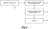
- Fig.4 is a structural block diagram of a device for suppressing fluctuations in compressor speed according to another aspect of the present invention.
- a shaft error acquisition unit 21 configured to obtain a shaft error ⁇ which reflects a deviation of an actual position of a compressor rotor from an estimated position of a compressor rotor;
- An angular velocity compensation amount acquisition unit 22 configured to filter the shaft error ⁇ to obtain a corrected shaft error ⁇ ' in which at least a part of shaft error fluctuation is eliminated and an angular velocity compensation amount P_out according to the corrected shaft error ⁇ '.
- a control unit 24 is configured to correct the real-time angular velocity ⁇ 1 which is used for compressor control according to the compensated angular velocity output and control the compressor according to the corrected real-time angular velocity ⁇ 1.
- the device with the above-mentioned structural units could be applied to compressors, such as air conditioners.
- the compressors with such a device could run corresponding program and work according to the process of the above-mentioned method and the preferred embodiments, so as to suppress the fluctuation on the compressor speed and realize the technical effects of the above method embodiments.
Landscapes
- Engineering & Computer Science (AREA)
- Mechanical Engineering (AREA)
- General Engineering & Computer Science (AREA)
- Power Engineering (AREA)
- Control Of Ac Motors In General (AREA)
- Control Of Motors That Do Not Use Commutators (AREA)
- Control Of Electric Motors In General (AREA)
- Control Of Positive-Displacement Air Blowers (AREA)
Applications Claiming Priority (2)
| Application Number | Priority Date | Filing Date | Title |
|---|---|---|---|
| CN201811531816.1A CN109724335B (zh) | 2018-12-13 | 2018-12-13 | 抑制压缩机转速波动的方法和装置 |
| PCT/CN2019/106826 WO2020119209A1 (zh) | 2018-12-13 | 2019-09-20 | 抑制压缩机转速波动的方法和装置 |
Publications (3)
| Publication Number | Publication Date |
|---|---|
| EP3896366A1 true EP3896366A1 (de) | 2021-10-20 |
| EP3896366A4 EP3896366A4 (de) | 2022-03-09 |
| EP3896366B1 EP3896366B1 (de) | 2023-06-28 |
Family
ID=66295995
Family Applications (1)
| Application Number | Title | Priority Date | Filing Date |
|---|---|---|---|
| EP19896103.9A Active EP3896366B1 (de) | 2018-12-13 | 2019-09-20 | Verfahren und vorrichtung zur steuerung der rotationsdrehzahlschwankung eines verdichters |
Country Status (4)
| Country | Link |
|---|---|
| EP (1) | EP3896366B1 (de) |
| CN (1) | CN109724335B (de) |
| ES (1) | ES2954066T3 (de) |
| WO (1) | WO2020119209A1 (de) |
Families Citing this family (2)
| Publication number | Priority date | Publication date | Assignee | Title |
|---|---|---|---|---|
| CN109724335B (zh) * | 2018-12-13 | 2021-04-20 | 青岛海尔空调器有限总公司 | 抑制压缩机转速波动的方法和装置 |
| CN112564571B (zh) * | 2019-09-25 | 2022-09-27 | 杭州先途电子有限公司 | 一种控制方法、控制装置及控制器 |
Family Cites Families (13)
| Publication number | Priority date | Publication date | Assignee | Title |
|---|---|---|---|---|
| JP4834129B2 (ja) * | 2009-05-29 | 2011-12-14 | 東芝シュネデール・インバータ株式会社 | 速度センサレスベクトル制御装置 |
| JP5175887B2 (ja) * | 2010-03-23 | 2013-04-03 | 株式会社東芝 | モータ制御装置及び電気機器 |
| JP2012005199A (ja) * | 2010-06-15 | 2012-01-05 | Toshiba Corp | モータ制御装置、圧縮機およびヒートポンプ装置 |
| JP5757205B2 (ja) * | 2011-09-16 | 2015-07-29 | 富士電機株式会社 | 永久磁石形同期電動機の制御装置 |
| CN103967794B (zh) * | 2013-02-05 | 2016-01-20 | 广东美的制冷设备有限公司 | 一种单转子压缩机的振动补偿方法及控制器 |
| JP5882246B2 (ja) * | 2013-03-07 | 2016-03-09 | 日立アプライアンス株式会社 | モータ制御装置 |
| CN103296958B (zh) * | 2013-05-22 | 2016-01-13 | 四川长虹电器股份有限公司 | 一种转矩自动补偿方法及转矩自动补偿系统 |
| CN105515484B (zh) * | 2016-01-14 | 2018-09-25 | 广东美芝制冷设备有限公司 | 压缩机的回转振动的抑制方法和装置及压缩机控制系统 |
| JP6769050B2 (ja) * | 2016-03-04 | 2020-10-14 | 株式会社富士通ゼネラル | モータ制御装置 |
| CN106026818B (zh) * | 2016-07-04 | 2019-01-18 | 广东美的制冷设备有限公司 | 压缩机转矩补偿方法、装置及空调 |
| CN106788071B (zh) * | 2017-01-06 | 2019-01-29 | 南京航空航天大学 | 一种提高永磁同步电机转子位置估计精度的方法 |
| CN109724335B (zh) * | 2018-12-13 | 2021-04-20 | 青岛海尔空调器有限总公司 | 抑制压缩机转速波动的方法和装置 |
| CN109724297B (zh) * | 2018-12-13 | 2021-04-20 | 青岛海尔空调器有限总公司 | 压缩机转速波动控制方法 |
-
2018
- 2018-12-13 CN CN201811531816.1A patent/CN109724335B/zh active Active
-
2019
- 2019-09-20 WO PCT/CN2019/106826 patent/WO2020119209A1/zh not_active Ceased
- 2019-09-20 ES ES19896103T patent/ES2954066T3/es active Active
- 2019-09-20 EP EP19896103.9A patent/EP3896366B1/de active Active
Also Published As
| Publication number | Publication date |
|---|---|
| WO2020119209A1 (zh) | 2020-06-18 |
| CN109724335A (zh) | 2019-05-07 |
| CN109724335B (zh) | 2021-04-20 |
| EP3896366B1 (de) | 2023-06-28 |
| ES2954066T3 (es) | 2023-11-20 |
| EP3896366A4 (de) | 2022-03-09 |
Similar Documents
| Publication | Publication Date | Title |
|---|---|---|
| EP3896365B1 (de) | Verfahren zur steuerung der drehzahlschwankung eines verdichters | |
| EP3896842B1 (de) | Verfahren zur regelung der drehzahlschwankung eines einzelrotorverdichters | |
| EP3896366B1 (de) | Verfahren und vorrichtung zur steuerung der rotationsdrehzahlschwankung eines verdichters | |
| CN109458336B (zh) | 用于控制单转子压缩机转速的方法 | |
| CN109450331B (zh) | 一种抑制压缩机转速波动的方法及装置 | |
| CN109660173B (zh) | 抑制单转子压缩机转速波动的方法和装置 | |
| CN109510555B (zh) | 抑制压缩机转速波动的方法及装置 | |
| CN109724302B (zh) | 空调压缩机转速控制方法 | |
| CN109698647B (zh) | 一种空调压缩机转速波动抑制方法 | |
| CN109458338B (zh) | 单转子压缩机转速控制方法 | |
| CN109660172B (zh) | 一种抑制压缩机转速波动的方法和装置 | |
| CN109742994B (zh) | 抑制单转子压缩机转速波动的方法 | |
| CN109724300B (zh) | 用于压缩机转速控制的方法 | |
| CN109713965B (zh) | 一种抑制空调压缩机转速波动的方法及装置 | |
| CN109724306B (zh) | 压缩机转速控制方法 | |
| CN109469613B (zh) | 抑制压缩机转速波动的方法 | |
| CN109742996B (zh) | 用于空调压缩机转速波动控制的方法 | |
| CN109458339B (zh) | 用于单转子压缩机转速控制的方法 | |
| CN109724312B (zh) | 一种空调压缩机转速控制方法 | |
| CN109724304B (zh) | 控制压缩机转速的方法 | |
| CN109458337B (zh) | 控制单转子压缩机转速的方法 | |
| CN109724303B (zh) | 压缩机转速波动抑制方法 | |
| CN109713966B (zh) | 抑制空调压缩机转速波动的方法及装置 | |
| CN109724301B (zh) | 一种压缩机转速波动抑制方法 | |
| CN109698645B (zh) | 用于控制单转子压缩机转速波动的方法 |
Legal Events
| Date | Code | Title | Description |
|---|---|---|---|
| STAA | Information on the status of an ep patent application or granted ep patent |
Free format text: STATUS: THE INTERNATIONAL PUBLICATION HAS BEEN MADE |
|
| PUAI | Public reference made under article 153(3) epc to a published international application that has entered the european phase |
Free format text: ORIGINAL CODE: 0009012 |
|
| STAA | Information on the status of an ep patent application or granted ep patent |
Free format text: STATUS: REQUEST FOR EXAMINATION WAS MADE |
|
| 17P | Request for examination filed |
Effective date: 20210621 |
|
| AK | Designated contracting states |
Kind code of ref document: A1 Designated state(s): AL AT BE BG CH CY CZ DE DK EE ES FI FR GB GR HR HU IE IS IT LI LT LU LV MC MK MT NL NO PL PT RO RS SE SI SK SM TR |
|
| A4 | Supplementary search report drawn up and despatched |
Effective date: 20220204 |
|
| RIC1 | Information provided on ipc code assigned before grant |
Ipc: H02P 21/05 20060101ALI20220131BHEP Ipc: F04C 28/28 20060101ALI20220131BHEP Ipc: F04C 28/08 20060101ALI20220131BHEP Ipc: F24F 11/86 20180101ALI20220131BHEP Ipc: F25B 49/02 20060101AFI20220131BHEP |
|
| DAV | Request for validation of the european patent (deleted) | ||
| DAX | Request for extension of the european patent (deleted) | ||
| RIC1 | Information provided on ipc code assigned before grant |
Ipc: H02P 21/05 20060101ALI20221114BHEP Ipc: F04C 28/28 20060101ALI20221114BHEP Ipc: F04C 28/08 20060101ALI20221114BHEP Ipc: F24F 11/86 20180101ALI20221114BHEP Ipc: F25B 49/02 20060101AFI20221114BHEP |
|
| GRAP | Despatch of communication of intention to grant a patent |
Free format text: ORIGINAL CODE: EPIDOSNIGR1 |
|
| STAA | Information on the status of an ep patent application or granted ep patent |
Free format text: STATUS: GRANT OF PATENT IS INTENDED |
|
| INTG | Intention to grant announced |
Effective date: 20230125 |
|
| GRAS | Grant fee paid |
Free format text: ORIGINAL CODE: EPIDOSNIGR3 |
|
| GRAA | (expected) grant |
Free format text: ORIGINAL CODE: 0009210 |
|
| STAA | Information on the status of an ep patent application or granted ep patent |
Free format text: STATUS: THE PATENT HAS BEEN GRANTED |
|
| AK | Designated contracting states |
Kind code of ref document: B1 Designated state(s): AL AT BE BG CH CY CZ DE DK EE ES FI FR GB GR HR HU IE IS IT LI LT LU LV MC MK MT NL NO PL PT RO RS SE SI SK SM TR |
|
| REG | Reference to a national code |
Ref country code: CH Ref legal event code: EP |
|
| REG | Reference to a national code |
Ref country code: AT Ref legal event code: REF Ref document number: 1583014 Country of ref document: AT Kind code of ref document: T Effective date: 20230715 |
|
| REG | Reference to a national code |
Ref country code: IE Ref legal event code: FG4D |
|
| REG | Reference to a national code |
Ref country code: DE Ref legal event code: R096 Ref document number: 602019031915 Country of ref document: DE |
|
| REG | Reference to a national code |
Ref country code: LT Ref legal event code: MG9D |
|
| PG25 | Lapsed in a contracting state [announced via postgrant information from national office to epo] |
Ref country code: SE Free format text: LAPSE BECAUSE OF FAILURE TO SUBMIT A TRANSLATION OF THE DESCRIPTION OR TO PAY THE FEE WITHIN THE PRESCRIBED TIME-LIMIT Effective date: 20230628 Ref country code: NO Free format text: LAPSE BECAUSE OF FAILURE TO SUBMIT A TRANSLATION OF THE DESCRIPTION OR TO PAY THE FEE WITHIN THE PRESCRIBED TIME-LIMIT Effective date: 20230928 |
|
| REG | Reference to a national code |
Ref country code: NL Ref legal event code: MP Effective date: 20230628 |
|
| REG | Reference to a national code |
Ref country code: AT Ref legal event code: MK05 Ref document number: 1583014 Country of ref document: AT Kind code of ref document: T Effective date: 20230628 |
|
| REG | Reference to a national code |
Ref country code: ES Ref legal event code: FG2A Ref document number: 2954066 Country of ref document: ES Kind code of ref document: T3 Effective date: 20231120 |
|
| PG25 | Lapsed in a contracting state [announced via postgrant information from national office to epo] |
Ref country code: RS Free format text: LAPSE BECAUSE OF FAILURE TO SUBMIT A TRANSLATION OF THE DESCRIPTION OR TO PAY THE FEE WITHIN THE PRESCRIBED TIME-LIMIT Effective date: 20230628 Ref country code: NL Free format text: LAPSE BECAUSE OF FAILURE TO SUBMIT A TRANSLATION OF THE DESCRIPTION OR TO PAY THE FEE WITHIN THE PRESCRIBED TIME-LIMIT Effective date: 20230628 Ref country code: LV Free format text: LAPSE BECAUSE OF FAILURE TO SUBMIT A TRANSLATION OF THE DESCRIPTION OR TO PAY THE FEE WITHIN THE PRESCRIBED TIME-LIMIT Effective date: 20230628 Ref country code: LT Free format text: LAPSE BECAUSE OF FAILURE TO SUBMIT A TRANSLATION OF THE DESCRIPTION OR TO PAY THE FEE WITHIN THE PRESCRIBED TIME-LIMIT Effective date: 20230628 Ref country code: HR Free format text: LAPSE BECAUSE OF FAILURE TO SUBMIT A TRANSLATION OF THE DESCRIPTION OR TO PAY THE FEE WITHIN THE PRESCRIBED TIME-LIMIT Effective date: 20230628 Ref country code: GR Free format text: LAPSE BECAUSE OF FAILURE TO SUBMIT A TRANSLATION OF THE DESCRIPTION OR TO PAY THE FEE WITHIN THE PRESCRIBED TIME-LIMIT Effective date: 20230929 |
|
| PG25 | Lapsed in a contracting state [announced via postgrant information from national office to epo] |
Ref country code: FI Free format text: LAPSE BECAUSE OF FAILURE TO SUBMIT A TRANSLATION OF THE DESCRIPTION OR TO PAY THE FEE WITHIN THE PRESCRIBED TIME-LIMIT Effective date: 20230628 |
|
| PG25 | Lapsed in a contracting state [announced via postgrant information from national office to epo] |
Ref country code: SK Free format text: LAPSE BECAUSE OF FAILURE TO SUBMIT A TRANSLATION OF THE DESCRIPTION OR TO PAY THE FEE WITHIN THE PRESCRIBED TIME-LIMIT Effective date: 20230628 |
|
| PG25 | Lapsed in a contracting state [announced via postgrant information from national office to epo] |
Ref country code: IS Free format text: LAPSE BECAUSE OF FAILURE TO SUBMIT A TRANSLATION OF THE DESCRIPTION OR TO PAY THE FEE WITHIN THE PRESCRIBED TIME-LIMIT Effective date: 20231028 |
|
| PG25 | Lapsed in a contracting state [announced via postgrant information from national office to epo] |
Ref country code: SM Free format text: LAPSE BECAUSE OF FAILURE TO SUBMIT A TRANSLATION OF THE DESCRIPTION OR TO PAY THE FEE WITHIN THE PRESCRIBED TIME-LIMIT Effective date: 20230628 Ref country code: SK Free format text: LAPSE BECAUSE OF FAILURE TO SUBMIT A TRANSLATION OF THE DESCRIPTION OR TO PAY THE FEE WITHIN THE PRESCRIBED TIME-LIMIT Effective date: 20230628 Ref country code: RO Free format text: LAPSE BECAUSE OF FAILURE TO SUBMIT A TRANSLATION OF THE DESCRIPTION OR TO PAY THE FEE WITHIN THE PRESCRIBED TIME-LIMIT Effective date: 20230628 Ref country code: PT Free format text: LAPSE BECAUSE OF FAILURE TO SUBMIT A TRANSLATION OF THE DESCRIPTION OR TO PAY THE FEE WITHIN THE PRESCRIBED TIME-LIMIT Effective date: 20231030 Ref country code: IS Free format text: LAPSE BECAUSE OF FAILURE TO SUBMIT A TRANSLATION OF THE DESCRIPTION OR TO PAY THE FEE WITHIN THE PRESCRIBED TIME-LIMIT Effective date: 20231028 Ref country code: EE Free format text: LAPSE BECAUSE OF FAILURE TO SUBMIT A TRANSLATION OF THE DESCRIPTION OR TO PAY THE FEE WITHIN THE PRESCRIBED TIME-LIMIT Effective date: 20230628 Ref country code: CZ Free format text: LAPSE BECAUSE OF FAILURE TO SUBMIT A TRANSLATION OF THE DESCRIPTION OR TO PAY THE FEE WITHIN THE PRESCRIBED TIME-LIMIT Effective date: 20230628 Ref country code: AT Free format text: LAPSE BECAUSE OF FAILURE TO SUBMIT A TRANSLATION OF THE DESCRIPTION OR TO PAY THE FEE WITHIN THE PRESCRIBED TIME-LIMIT Effective date: 20230628 |
|
| PG25 | Lapsed in a contracting state [announced via postgrant information from national office to epo] |
Ref country code: PL Free format text: LAPSE BECAUSE OF FAILURE TO SUBMIT A TRANSLATION OF THE DESCRIPTION OR TO PAY THE FEE WITHIN THE PRESCRIBED TIME-LIMIT Effective date: 20230628 |
|
| REG | Reference to a national code |
Ref country code: DE Ref legal event code: R097 Ref document number: 602019031915 Country of ref document: DE |
|
| PG25 | Lapsed in a contracting state [announced via postgrant information from national office to epo] |
Ref country code: DK Free format text: LAPSE BECAUSE OF FAILURE TO SUBMIT A TRANSLATION OF THE DESCRIPTION OR TO PAY THE FEE WITHIN THE PRESCRIBED TIME-LIMIT Effective date: 20230628 |
|
| REG | Reference to a national code |
Ref country code: CH Ref legal event code: PL |
|
| PLBE | No opposition filed within time limit |
Free format text: ORIGINAL CODE: 0009261 |
|
| STAA | Information on the status of an ep patent application or granted ep patent |
Free format text: STATUS: NO OPPOSITION FILED WITHIN TIME LIMIT |
|
| PG25 | Lapsed in a contracting state [announced via postgrant information from national office to epo] |
Ref country code: LU Free format text: LAPSE BECAUSE OF NON-PAYMENT OF DUE FEES Effective date: 20230920 |
|
| REG | Reference to a national code |
Ref country code: BE Ref legal event code: MM Effective date: 20230930 |
|
| GBPC | Gb: european patent ceased through non-payment of renewal fee |
Effective date: 20230928 |
|
| PG25 | Lapsed in a contracting state [announced via postgrant information from national office to epo] |
Ref country code: LU Free format text: LAPSE BECAUSE OF NON-PAYMENT OF DUE FEES Effective date: 20230920 Ref country code: MC Free format text: LAPSE BECAUSE OF FAILURE TO SUBMIT A TRANSLATION OF THE DESCRIPTION OR TO PAY THE FEE WITHIN THE PRESCRIBED TIME-LIMIT Effective date: 20230628 |
|
| 26N | No opposition filed |
Effective date: 20240402 |
|
| REG | Reference to a national code |
Ref country code: IE Ref legal event code: MM4A |
|
| PG25 | Lapsed in a contracting state [announced via postgrant information from national office to epo] |
Ref country code: IE Free format text: LAPSE BECAUSE OF NON-PAYMENT OF DUE FEES Effective date: 20230920 |
|
| PG25 | Lapsed in a contracting state [announced via postgrant information from national office to epo] |
Ref country code: GB Free format text: LAPSE BECAUSE OF NON-PAYMENT OF DUE FEES Effective date: 20230928 |
|
| PG25 | Lapsed in a contracting state [announced via postgrant information from national office to epo] |
Ref country code: CH Free format text: LAPSE BECAUSE OF NON-PAYMENT OF DUE FEES Effective date: 20230930 |
|
| PG25 | Lapsed in a contracting state [announced via postgrant information from national office to epo] |
Ref country code: IE Free format text: LAPSE BECAUSE OF NON-PAYMENT OF DUE FEES Effective date: 20230920 Ref country code: GB Free format text: LAPSE BECAUSE OF NON-PAYMENT OF DUE FEES Effective date: 20230928 Ref country code: CH Free format text: LAPSE BECAUSE OF NON-PAYMENT OF DUE FEES Effective date: 20230930 Ref country code: SI Free format text: LAPSE BECAUSE OF FAILURE TO SUBMIT A TRANSLATION OF THE DESCRIPTION OR TO PAY THE FEE WITHIN THE PRESCRIBED TIME-LIMIT Effective date: 20230628 |
|
| PG25 | Lapsed in a contracting state [announced via postgrant information from national office to epo] |
Ref country code: BE Free format text: LAPSE BECAUSE OF NON-PAYMENT OF DUE FEES Effective date: 20230930 |
|
| PG25 | Lapsed in a contracting state [announced via postgrant information from national office to epo] |
Ref country code: BG Free format text: LAPSE BECAUSE OF FAILURE TO SUBMIT A TRANSLATION OF THE DESCRIPTION OR TO PAY THE FEE WITHIN THE PRESCRIBED TIME-LIMIT Effective date: 20230628 |
|
| PG25 | Lapsed in a contracting state [announced via postgrant information from national office to epo] |
Ref country code: BG Free format text: LAPSE BECAUSE OF FAILURE TO SUBMIT A TRANSLATION OF THE DESCRIPTION OR TO PAY THE FEE WITHIN THE PRESCRIBED TIME-LIMIT Effective date: 20230628 |
|
| PG25 | Lapsed in a contracting state [announced via postgrant information from national office to epo] |
Ref country code: IT Free format text: LAPSE BECAUSE OF NON-PAYMENT OF DUE FEES Effective date: 20230920 |
|
| PG25 | Lapsed in a contracting state [announced via postgrant information from national office to epo] |
Ref country code: IT Free format text: LAPSE BECAUSE OF NON-PAYMENT OF DUE FEES Effective date: 20230920 |
|
| PG25 | Lapsed in a contracting state [announced via postgrant information from national office to epo] |
Ref country code: CY Free format text: LAPSE BECAUSE OF FAILURE TO SUBMIT A TRANSLATION OF THE DESCRIPTION OR TO PAY THE FEE WITHIN THE PRESCRIBED TIME-LIMIT; INVALID AB INITIO Effective date: 20190920 |
|
| PG25 | Lapsed in a contracting state [announced via postgrant information from national office to epo] |
Ref country code: HU Free format text: LAPSE BECAUSE OF FAILURE TO SUBMIT A TRANSLATION OF THE DESCRIPTION OR TO PAY THE FEE WITHIN THE PRESCRIBED TIME-LIMIT; INVALID AB INITIO Effective date: 20190920 |
|
| PGFP | Annual fee paid to national office [announced via postgrant information from national office to epo] |
Ref country code: DE Payment date: 20250919 Year of fee payment: 7 |
|
| PGFP | Annual fee paid to national office [announced via postgrant information from national office to epo] |
Ref country code: TR Payment date: 20250901 Year of fee payment: 7 |
|
| PGFP | Annual fee paid to national office [announced via postgrant information from national office to epo] |
Ref country code: FR Payment date: 20250922 Year of fee payment: 7 |
|
| PGFP | Annual fee paid to national office [announced via postgrant information from national office to epo] |
Ref country code: ES Payment date: 20251001 Year of fee payment: 7 |