EP3895981A1 - Marine power supply system and method for controlling marine power supply system - Google Patents
Marine power supply system and method for controlling marine power supply system Download PDFInfo
- Publication number
- EP3895981A1 EP3895981A1 EP21164874.6A EP21164874A EP3895981A1 EP 3895981 A1 EP3895981 A1 EP 3895981A1 EP 21164874 A EP21164874 A EP 21164874A EP 3895981 A1 EP3895981 A1 EP 3895981A1
- Authority
- EP
- European Patent Office
- Prior art keywords
- battery
- state
- battery switch
- power
- marine
- Prior art date
- Legal status (The legal status is an assumption and is not a legal conclusion. Google has not performed a legal analysis and makes no representation as to the accuracy of the status listed.)
- Pending
Links
Images



Classifications
-
- B—PERFORMING OPERATIONS; TRANSPORTING
- B63—SHIPS OR OTHER WATERBORNE VESSELS; RELATED EQUIPMENT
- B63H—MARINE PROPULSION OR STEERING
- B63H21/00—Use of propulsion power plant or units on vessels
- B63H21/20—Use of propulsion power plant or units on vessels the vessels being powered by combinations of different types of propulsion units
-
- B—PERFORMING OPERATIONS; TRANSPORTING
- B63—SHIPS OR OTHER WATERBORNE VESSELS; RELATED EQUIPMENT
- B63H—MARINE PROPULSION OR STEERING
- B63H21/00—Use of propulsion power plant or units on vessels
- B63H21/22—Use of propulsion power plant or units on vessels the propulsion power units being controlled from exterior of engine room, e.g. from navigation bridge; Arrangements of order telegraphs
-
- B—PERFORMING OPERATIONS; TRANSPORTING
- B63—SHIPS OR OTHER WATERBORNE VESSELS; RELATED EQUIPMENT
- B63B—SHIPS OR OTHER WATERBORNE VESSELS; EQUIPMENT FOR SHIPPING
- B63B79/00—Monitoring properties or operating parameters of vessels in operation
- B63B79/40—Monitoring properties or operating parameters of vessels in operation for controlling the operation of vessels, e.g. monitoring their speed, routing or maintenance schedules
-
- B—PERFORMING OPERATIONS; TRANSPORTING
- B63—SHIPS OR OTHER WATERBORNE VESSELS; RELATED EQUIPMENT
- B63H—MARINE PROPULSION OR STEERING
- B63H21/00—Use of propulsion power plant or units on vessels
- B63H21/21—Control means for engine or transmission, specially adapted for use on marine vessels
-
- B—PERFORMING OPERATIONS; TRANSPORTING
- B63—SHIPS OR OTHER WATERBORNE VESSELS; RELATED EQUIPMENT
- B63H—MARINE PROPULSION OR STEERING
- B63H20/00—Outboard propulsion units, e.g. outboard motors or Z-drives; Arrangements thereof on vessels
-
- B—PERFORMING OPERATIONS; TRANSPORTING
- B63—SHIPS OR OTHER WATERBORNE VESSELS; RELATED EQUIPMENT
- B63H—MARINE PROPULSION OR STEERING
- B63H20/00—Outboard propulsion units, e.g. outboard motors or Z-drives; Arrangements thereof on vessels
- B63H2020/003—Arrangements of two, or more outboard propulsion units
-
- B—PERFORMING OPERATIONS; TRANSPORTING
- B63—SHIPS OR OTHER WATERBORNE VESSELS; RELATED EQUIPMENT
- B63H—MARINE PROPULSION OR STEERING
- B63H21/00—Use of propulsion power plant or units on vessels
- B63H21/20—Use of propulsion power plant or units on vessels the vessels being powered by combinations of different types of propulsion units
- B63H2021/202—Use of propulsion power plant or units on vessels the vessels being powered by combinations of different types of propulsion units of hybrid electric type
-
- B—PERFORMING OPERATIONS; TRANSPORTING
- B63—SHIPS OR OTHER WATERBORNE VESSELS; RELATED EQUIPMENT
- B63H—MARINE PROPULSION OR STEERING
- B63H21/00—Use of propulsion power plant or units on vessels
- B63H21/21—Control means for engine or transmission, specially adapted for use on marine vessels
- B63H2021/216—Control means for engine or transmission, specially adapted for use on marine vessels using electric control means
-
- Y—GENERAL TAGGING OF NEW TECHNOLOGICAL DEVELOPMENTS; GENERAL TAGGING OF CROSS-SECTIONAL TECHNOLOGIES SPANNING OVER SEVERAL SECTIONS OF THE IPC; TECHNICAL SUBJECTS COVERED BY FORMER USPC CROSS-REFERENCE ART COLLECTIONS [XRACs] AND DIGESTS
- Y02—TECHNOLOGIES OR APPLICATIONS FOR MITIGATION OR ADAPTATION AGAINST CLIMATE CHANGE
- Y02T—CLIMATE CHANGE MITIGATION TECHNOLOGIES RELATED TO TRANSPORTATION
- Y02T70/00—Maritime or waterways transport
- Y02T70/50—Measures to reduce greenhouse gas emissions related to the propulsion system
- Y02T70/5218—Less carbon-intensive fuels, e.g. natural gas, biofuels
- Y02T70/5236—Renewable or hybrid-electric solutions
Definitions
- the present invention relates to a marine power supply system and a method for controlling a marine power supply system.
- a marine power supply system that supplies power to a marine propulsion unit including an engine and an electric motor and a method for controlling a marine power supply system are known in general.
- Such a marine power supply system and a method for controlling a marine power supply system are disclosed in Japanese Patent Laid-Open No. 2017-218016 , for example.
- Japanese Patent Laid-Open No. 2017-218016 discloses a marine vessel including a marine propulsion device including an engine and an electric motor.
- the marine propulsion device includes a propeller. Both the engine and the electric motor generate power to rotate the propeller.
- the marine vessel includes a battery to supply power to the electric motor. The electric motor rotates the propeller using the power from the battery.
- the marine vessel includes a battery switch to be manually switched between a state in which the battery is used (hereinafter referred to as an "on-state”) and a state in which the battery is not used (hereinafter referred to as an "off-state”) in order to significantly reduce or prevent discharge from the battery due to dark current, for example, during storage of the marine vessel.
- a battery switch is conceivably provided between the electric motor and a battery.
- the propeller rotates to propel the marine vessel only by driving the engine.
- the marine vessel conceivably travels without a user being aware that the battery switch is in an off-state. Therefore, a marine power supply system and a method for controlling a marine power supply system that significantly reduce or prevent traveling of a marine vessel without a user being aware that a battery switch is in an off-state even when power is supplied to a marine propulsion device (marine propulsion unit) including an engine and an electric motor have been desired.
- a marine propulsion device marine propulsion unit
- said object is solved by a marine power supply system and a method for controlling a marine power supply system having the features of independent claims 1 and 12. Preferred embodiments are laid down in the dependent claims.
- a marine power supply system is configured to supply power to a marine propulsion unit including a propulsion generator configured to generate a propulsive force to propel a marine vessel, an engine configured to drive the propulsion generator, and an electric motor configured to drive the propulsion generator, and includes a first battery configured to supply power to the electric motor, a battery switch configured to be manually switched between an on-state in which the first battery is used and an off-state in which the first battery is not used, and a notifier configured to provide a notification indicating that the battery switch is in the off-state when the battery switch is in the off-state.
- a marine power supply system includes the notifier to provide the notification indicating that the battery switch is in the off-state when the battery switch is in the off-state. Accordingly, the notifier notifies a user that the battery switch is in the off-state. Consequently, even when power is supplied to the marine propulsion unit including the engine and the electric motor, traveling of the marine vessel without the user being aware that the battery switch is in the off-state is significantly reduced or prevented.
- a marine power supply system preferably further includes a controller configured or programmed to control the notifier to provide the notification indicating that the battery switch is in the off-state when the battery switch is in the off-state. Accordingly, the notifier is easily controlled using the controller.
- the notifier preferably includes a display
- the controller is preferably configured or programmed to control the display to provide a display indicating that the battery switch is in the off-state when the battery switch is in the off-state. Accordingly, the user easily recognizes that the battery switch is in the off-state by visually recognizing the display.
- the controller is preferably configured or programmed to control the display to display message information indicating that the battery switch is in the off-state when the battery switch is in the off-state. Accordingly, the user easily recognizes that the battery switch is in the off-state by reading the message information on the display.
- the controller is preferably configured or programmed to perform a control to switch between an engine driving state in which the propulsion generator is driven by the engine and an electric motor driving state in which the propulsion generator is driven by the electric motor. Accordingly, the controller functions as a controller for a hybrid system configured or programmed to perform a control to switch between the engine driving state and the electric motor driving state, and also functions as a controller configured or programmed to control the notifier. Consequently, as compared with a case in which the controller for the hybrid system is separated from the controller configured or programmed to control the notifier, a complex structure of the marine vessel including the marine power supply system is significantly reduced or prevented.
- a marine power supply system configured to switch between the engine driving state and the electric motor driving state preferably further includes a starter connected to the engine to start the engine, and a second battery provided separately from the first battery to supply power to the starter, and the controller is preferably configured or programmed to control the notifier to provide the notification indicating that the battery switch is in the off-state and to control the engine to start when power is supplied from the second battery to the starter and when the battery switch is in the off-state. Accordingly, the engine is started even when the notification indicating that the battery switch is in the off-state is provided. Consequently, even when the battery switch is in the off-state, the engine is started when the user desires to start the engine.
- a marine power supply system preferably further includes a detector provided between the battery switch and the electric motor to detect that the battery switch is in the off-state. Accordingly, the user easily recognizes that the battery switch is in the off-state through the notifier based on the detection result detected by the detector.
- a marine power supply system preferably further includes a power converter configured to convert DC power from the battery switch into AC power to supply the AC power to the electric motor, and a power conversion controller configured or programmed to control operation of the power converter and to also serve as the detector. Accordingly, it is not necessary to provide a dedicated detector to detect that the battery switch is in the off-state. Thus, an increase in the number of components of the marine power supply system is significantly reduced or prevented, and a complex structure of the marine power supply system is significantly reduced or prevented.
- a marine power supply system including the power conversion controller preferably further includes a third battery provided separately from the first battery to supply power to the power conversion controller. Accordingly, even when power is not supplied from the first battery to the power conversion controller, the power conversion controller detects that the battery switch is in the off-state using the power from the third battery.
- a marine power supply system including the detector preferably further includes a storage configured to store a detection result detected by the detector. Accordingly, the user or a maintenance worker is able to retroactively confirm the detection result stored in the storage.
- the first battery preferably includes a plurality of first batteries
- the battery switch preferably includes a plurality of battery switches
- the notifier is preferably configured to provide a notification indicating that at least one of the plurality of battery switches is in the off-state when the at least one of the plurality of battery switches is in the off-state. Accordingly, even when the plurality of battery switches are provided, the user is notified that at least one of the plurality of battery switches is in the off-state when at least one of the plurality of battery switches is in the off-state.
- a method for controlling a marine power supply system configured to supply power to a marine propulsion unit including a propulsion generator configured to generate a propulsive force to propel a marine vessel, an engine configured to drive the propulsion generator, and an electric motor configured to drive the propulsion generator according to a preferred embodiment includes acquiring that a battery switch configured to be manually switched between an on-state in which a first battery configured to supply power to the electric motor is used and an off-state in which the first battery is not used is in the off-state, and providing a notification indicating that the battery switch is in the off-state based on acquiring that the battery switch is in the off-state.
- the providing of the notification preferably includes providing a display indicating that the battery switch is in the off-state when the battery switch is in the off-state. Accordingly, the user easily recognizes that the battery switch is in the off-state by visually recognizing the display.
- the providing of the notification preferably includes displaying message information indicating that the battery switch is in the off-state when the battery switch is in the off-state. Accordingly, the user easily recognizes that the battery switch is in the off-state by reading the message information.
- the marine power supply system preferably further includes a starter connected to the engine to start the engine, and a second battery provided separately from the first battery to supply power to the starter, and the providing of the notification preferably includes providing the notification indicating that the battery switch is in the off-state and starting the engine when power is supplied from the second battery to the starter and when the battery switch is in the off-state. Accordingly, the engine is started even when the notification indicating that the battery switch is in the off-state is provided. Consequently, even when the battery switch is in the off-state, the engine is started when the user desires to start the engine.
- arrow FWD represents the forward movement direction of the marine vessel 100
- arrow BWD represents the reverse movement direction of the marine vessel 100.
- the marine vessel 100 includes a hull 1, outboard motors 2a and 2b, and a marine vessel control system 3. That is, the marine vessel 100 is an outboard motor boat. Furthermore, the marine vessel control system 3 is a power supply system that supplies power to the outboard motors 2a and 2b.
- the outboard motors 2a and 2b are examples of a "marine propulsion unit”.
- the marine vessel control system 3 is an example of a "marine power supply system”.
- the outboard motors 2a and 2b are attached to the hull 1.
- the outboard motors 2a and 2b are located side by side in a right-lest direction.
- the outboard motor 2a includes an engine 21, an electric motor 22, a propeller 23, an engine ECU (electronic control unit) 24, and a starter motor 25.
- the structure of the outboard motor 2b is the same as that of the outboard motor 2a.
- the propeller 23 is an example of a "propulsion generator”.
- the starter motor 25 is an example of a "starter”.
- the engine 21 drives the propeller 23.
- the engine 21 is an internal combustion engine driven by combustion of gasoline, light oil, or the like.
- the engine 21 is connected to the propeller 23 via a drive shaft 21a, etc.
- a driving force (rotational force) is transmitted the engine 21 to the propeller 23 such that the propeller 23 rotates, and the marine vessel 100 (hull 1) is propelled.
- the electric motor 22 drives the propeller 23.
- the electric motor 22 is a motor.
- the electric motor 22 provided in the outboard motor 2a is driven using power from an electric motor battery 34a described below.
- the electric motor 22 provided in the outboard motor 2b is driven using power from an electric motor battery 34b described below.
- the electric motor 22 provided in the outboard motor 2a is driven using power converted by an inverter device 5a described below.
- the electric motor 22 provided in the outboard motor 2b is driven using power converted by an inverter device 5b described below.
- the electric motor 22 is connected to the propeller 23 via a shaft 22a, a propeller shaft, etc.
- a driving force (rotational force) is transmitted from the electric motor 22 to the propeller 23 such that the propeller 23 rotates, and the marine vessel 100 (hull 1) is propelled.
- the propeller 23 is positioned in the water, and rotates to generate a propulsive force.
- the engine ECU 24 communicates with a hybrid controller 31 described below and the inverter device 5a or 5b provided in its own outboard motor 2a or 2b.
- the engine ECU 24 transmits and receives information and command signals to and from the hybrid controller 31 and the inverter device 5a or 5b by control area network (CAN) communication.
- CAN control area network
- the engine ECUs 24 are connected to a main battery 35, and operate using power from the main battery 35.
- the starter motors 25 start the engines 21. Specifically, the starter motors 25 are connected to the main battery 35, and are driven using power from the main battery 35. The starter motors 25 rotate (crank) crankshafts of the engines 21 based on commands from the engine ECUs 24 (hybrid controller 31). The engines 21 are cranked by the starter motors 25, fuel is supplied into the engines 21 by fuel suppliers (not shown), and the fuel in the engines 21 is ignited by igniters (not shown) to start the engines 21. Power is supplied from the main battery 35 to the fuel suppliers and the igniters.
- the marine vessel control system 3 includes the hybrid controller 31, a display 32, a marine vessel maneuvering unit 33, the electric motor batteries 34a and 34b, the main battery 35, a house battery 36, battery switches 4a and 4b, and inverter devices 5a and 5b.
- the hybrid controller 31 is an example of a "controller”.
- the display 32 is an example of a “notifier”.
- the electric motor batteries 34a and 34b are examples of a "first battery”.
- the main battery 35 is an example of a "second battery” or a "third battery”.
- the main battery 35 is provided to supply power to the starter 25, and the main battery 35 is provided to supply power to a power conversion controller 52 described later.
- a second battery provided to supply power to the starter 25 is provided separately from a third battery provided to supply power to the power conversion controller 52.
- the hybrid controller 31, the display 32, the marine vessel maneuvering unit 33, the electric motor batteries 34a and 34b, the main battery 35, the house battery 36, and the battery switches 4a and 4b are provided in the hull 1, for example.
- the display 32 is positioned in the vicinity of the marine vessel maneuvering unit 33, for example.
- the display 32 is provided at a position visually recognized by a user who operates the marine vessel maneuvering unit 33.
- a gauge such as an engine speed is displayed.
- the inverter device 5a is provided in the outboard motor 2a.
- the inverter device 5b is provided in the outboard motor 2b.
- the battery switches 4a and 4b are manually switched between on-states in which the electric motor batteries 34a and 34b are used and off-states in which the electric motor batteries 34a and 33b are not used, respectively.
- the battery switches 4a and 4b are connected in series between the electric motor battery 34a and the inverter device 5a and between the electric motor battery 34b and the inverter device 5b, respectively.
- the battery switch 4a is rotated or moved by the user such that a state in which the electric motor battery 34a and the inverter device 5a are conducted (the electric motor battery 34a is used) and a state in which the electric motor battery 34a and the inverter device 5a are shut off (the electric motor battery 34a is not used) are switched.
- the battery switch 4b is rotated or moved by the user such that a state in which the electric motor battery 34b and the inverter device 5b are conducted (the electric motor battery 34b is used) and a state in which the electric motor battery 34b and the inverter device 5b are shut off (the electric motor battery 34b is not used) are switched.
- the hybrid controller 31 is a control circuit that controls both driving of the engines 21 in the outboard motors 2a and 2b and driving of the electric motors 22 in the outboard motors 2a and 2b.
- the hybrid controller 31 includes a processor such as a CPU to perform an arithmetic process.
- the hybrid controller 31 is configured or programmed to perform a control to switch between an engine driving state in which the propellers 23 are driven by the engines 21 and an electric motor driving state in which the propellers 23 are driven by the electric motors 22.
- the hybrid controller 31 controls the outboard motors 2a and 2b in the electric motor driving state when the marine vessel 100 travels at a low speed, and controls the outboard motors 2a and 2b in the engine driving state when the marine vessel 100 travels at a high speed.
- the display 32 provides a notification indicating that at least one of the battery switch 4a or 4b is in an off-state when at least one of the battery switch 4a or 4b is in the off-state based on a command from the hybrid controller 31.
- the hybrid controller 31 is configured or programmed to control the display 32 to provide a notification indicating that at least one of the battery switch 4a or 4b is in the off-state when at least one of the battery switch 4a or 4b is in the off-state.
- the display 32 displays a message image P1, "first battery switch is in off-state", when the battery switch 4a is in the off-state based on a command from the hybrid controller 31.
- the display 32 displays a message image P2, "second battery switch is in off-state", when the battery switch 4b is in the off-state based on a command from the hybrid controller 31.
- the display 32 displays both the message images P1 and P2 when both the battery switches 4a and 4b are in the off-states based on a command from the hybrid controller 31.
- the message images P1 and P2 are examples of "message information”.
- the hybrid controller 31 is configured or programmed to control the display 32 to provide a notification indicating that at least one of the battery switch 4a or 4b is in the off-state and to control the engines 21 to start when power is supplied from the main battery 35 to the starter motors 25 and when at least one of the battery switch 4a or 4b is in the off-state. That is, the marine vessel 100 (both the outboard motors 2a and 2b) is able to start the engines 21 even when at least one of the battery switch 4a or 4b is in the off-state.
- the marine vessel maneuvering unit 33 includes a remote control, for example.
- the marine vessel maneuvering unit 33 receives input operations by the user and transmits operation signals based on the received input operations to the hybrid controller 31.
- the hybrid controller 31 controls the operation of the outboard motors 2a and 2b based on the operation signals.
- the electric motor battery 34a, the electric motor battery 34b, the main battery 35, and the house battery 36 are separated from each other.
- the electric motor battery 34a supplies power to the electric motor 22 via the inverter device 5a.
- the electric motor battery 34b supplies power to the electric motor 22 via the inverter device 5b.
- the main battery 35 supplies power to each of the starter motors 25 that start the engines 21 of the outboard motors 2a and 2b.
- the house battery 36 supplies power to at least some devices (devices in a house) other than the electric motors 22 and the starter motors 25 among devices in the marine vessel 100.
- the electric motor batteries 34a and 34b, the main battery 35, and the house battery 36 are lead storage batteries or lithium-ion batteries.
- the inverter devices 5a and 5b convert DC power from the electric motor batteries 34a and 34b into AC power based on commands from at least one of the hybrid controller 31 or the engine ECUs 24 to supply the AC power to the electric motors 22 of the outboard motors 2a and 2b in which the inverter devices 5a and 5b are located, respectively.
- the inverter device 5a is positioned between the battery switch 4a and the electric motor 22 of the outboard motor 2a.
- the inverter device 5b is positioned between the battery switch 4b and the electric motor 22 of the outboard motor 2b.
- the inverter device 5a includes a power converter 51, an inverter controller 52, and a storage 53.
- the structure of the inverter device 5b is the same as that of the inverter device 5a.
- the inverter controller 52 is an example of a "power conversion controller”.
- Each of the power converters 51 includes a switching circuit. Each of the power converters 51 converts DC power from the battery switch 4a or 4b corresponding to its own outboard motor 2a or 2b into AC power to supply the AC power to the corresponding electric motor 22.
- Each of the inverter controllers 52 includes a microcomputer.
- the inverter controllers 52 are configured or programmed to control the operation of the power converters 51.
- the inverter controller 52 provided in the outboard motor 2a is configured or programmed to detect that the battery switch 4a is in the off-state. Specifically, the inverter controller 52 detects that the battery switch 4a is in an on-state based on the electric motor battery 34a supplying power to the power converter 51 (a voltage being applied, for example), and detects that the battery switch 4a is in the off-state based on the electric motor battery 34a supplying no power to the power converter 51 (no voltage being applied, for example).
- Each of the storages 53 includes a non-volatile memory.
- Each of the storages 53 stores the date and time and information (detection result) indicating whether the battery switch 4a or 4b is in the off-state or the battery switch 4a or 4b is in the on-state in association with each other based on a command from the inverter controller 52.
- the hybrid controller 31 reads information in which the date and time and the detection result are associated with each other by accessing each of the storages 53, and controls the display 32 to display an image P3, which is the information in which the date and time and the detection result are associated with each other.
- FIG. 8 shows a flowchart of a control process in the marine vessel 100. The following control process is executed by the hybrid controller 31 and the inverter controllers 52.
- step S1 the inverter controller 52 of the outboard motor 2a acquires the detection result of whether or not the battery switch 4a is in the off-state, and the inverter controller 52 of the outboard motor 2b acquires the detection result of whether or not the battery switch 4b is in the off-state. Then, the process advances to step S2.
- step S2 the hybrid controller 31 determines whether or not at least one of the battery switch 4a or 4b is in the off-state. When at least one of the battery switch 4a or 4b is in the off-state, the process advances to step S3, and when each of the battery switches 4a and 4b is not in the off-state (is in the on-state), the process returns to step S1.
- step S3 at least one of the message image P1 indicating that the battery switch 4a is in the off-state or the message image P2 indicating that the battery switch 4b is in the off-state is displayed on the display 32. Then, the process returns to step S1.
- the marine vessel control system 3 includes the display 32 to provide a notification indicating that at least one of the battery switch 4a or 4b is in the off-state when at least one of the battery switch 4a or 4b is in the off-state. Accordingly, the display 32 notifies the user that at least one of the battery switch 4a or 4b is in the off-state. Consequently, even when power is supplied to the outboard motors 2a and 2b including the engines 21 and the electric motors 22, traveling of the marine vessel 100 without the user being aware that the battery switch 4a or 4b is in the off-state is significantly reduced or prevented.
- the marine vessel control system 3 includes the hybrid controller 31 configured or programmed to control the display 32 to provide a notification indicating that at least one of the battery switch 4a or 4b is in the off-state when at least one of the battery switch 4a or 4b is in the off-state. Accordingly, the display 32 is easily controlled using the hybrid controller 31.
- the hybrid controller 31 is configured or programmed to control the display 32 to provide a display indicating that at least one of the battery switch 4a or 4b is in the off-state when at least one of the battery switch 4a or 4b is in the off-state. Accordingly, the user easily recognizes that at least one of the battery switch 4a or 4b is in the off-state by visually recognizing the display 32.
- the hybrid controller 31 is configured or programmed to control the display 32 to display at least one of the message image P1 or P2 indicating that at least one of the battery switch 4a or 4b is in the off-state when at least one of the battery switch 4a or 4b is in the off-state. Accordingly, the user easily recognizes that at least one of the battery switch 4a or 4b is in the off-state by visually recognizing at least one of the message image P1 or P2 on the display 32 and reading the message content.
- the hybrid controller 31 is configured or programmed to perform a control to switch between the engine driving state in which the propellers 23 are driven by the engines 21 and the electric motor driving state in which the propellers 23 are driven by the electric motors 22. Accordingly, the hybrid controller 31 functions as a controller for a hybrid system configured or programmed to perform a control to switch between the engine driving state and the electric motor driving state, and also functions as a controller configured or programmed to control the display 32. Consequently, as compared with a case in which the controller for the hybrid system is separated from the controller configured or programmed to control the display 32, a complex structure of the marine vessel 100 including the marine vessel control system 3 is significantly reduced or prevented.
- the marine vessel control system 3 includes the starter motors 25 connected to the engines 21 to start the engines 21, and the main battery 35 provided separately from the electric motor batteries 34a and 34b to supply power to the starter motors 25.
- the hybrid controller 31 is configured or programmed to control the display 32 to provide a notification indicating that at least one of the battery switch 4a or 4b is in the off-state and to control the engines 21 to start when power is supplied from the main battery 35 to the starter motors 25 and when at least one of the battery switch 4a or 4b is in the off-state. Accordingly, the engines 21 are started even when the notification indicating that at least one of the battery switch 4a or 4b is in the off-state is provided. Consequently, even when at least one of the battery switch 4a or 4b is in the off-state, the engines 21 are started when the user desires to start the engines 21.
- the marine vessel control system 3 includes the inverter devices 5a and 5b (inverter controllers 52) provided between the battery switches 4a and 4b and the electric motors 22 to detect that at least one of the battery switch 4a or 4b is in the off-state. Accordingly, the user easily recognizes that at least one of the battery switch 4a or 4b is in the off-state through the display 32 based on the detection results detected by the inverter controllers 52.
- inverter controllers 52 inverter controllers 52
- the marine vessel control system 3 includes the power converters 51 to convert the DC power from the battery switches 4a and 4b into AC power to supply the AC power to the electric motors 22, and the inverter controllers 52 configured or programmed to control the operation of the power converters 51. Accordingly, it is not necessary to provide a dedicated controller to detect that at least one of the battery switch 4a or 4b is in the off-state. Thus, an increase in the number of components of the marine vessel control system 3 is significantly reduced or prevented, and a complex structure of the marine vessel control system 3 is significantly reduced or prevented.
- the marine vessel control system 3 includes the main battery 35 provided separately from the electric motor batteries 34a and 34b to supply power to the inverter controllers 52. Accordingly, even when power is not supplied from the electric motor batteries 34a and 34b to the inverter controllers 52, the inverter controllers 52 detect that at least one of the battery switch 4a or 4b is in the off-state using the power from the main battery 35.
- the marine vessel control system 3 includes the storages 53 to store the detection results detected by the inverter controllers 52. Accordingly, the user or a maintenance worker is able to retroactively confirm the detection results stored in the storages 53.
- the marine vessel control system 3 includes the electric motor batteries 34a and 34b, and the battery switches 4a and 4b. Furthermore, the display 32 provides a notification indicating that at least one of the battery switch 4a or 4b is in the off-state when at least one of a plurality of battery switches 4a and 4b is in the off-state. Accordingly, even when the battery switches 4a and 4b are provided, the user is notified that at least one of the battery switch 4a or 4b is in the off-state when at least one of the battery switch 4a or 4b is in the off-state.
- traveling of the marine vessel 100 without the user being aware that the battery switch 4a or 4b is the off-state is significantly reduced or prevented, similarly to the structure of the marine vessel control system 3.
- the marine vessel is preferably an outboard motor boat in preferred embodiments described above, the present teaching is not restricted to this. That is, the marine vessel may alternatively be a marine vessel other than an outboard motor boat.
- the marine vessel may be a marine vessel including an inboard motor(s), an inboard-outboard motor(s), or a jet propulsion device(s).
- main battery the electric motor batteries, and the house battery are preferably provided in the hull in preferred embodiments described above, the present teaching is not restricted to this. That is, at least one of the main battery, the electric motor batteries, or the house battery may alternatively be provided in the outboard motors.
- power is preferably supplied from the electric motor batteries only to the electric motors via the inverter devices in preferred embodiments described above, the present teaching is not restricted to this. That is, power may alternatively be supplied from the electric motor batteries to other devices in addition to the electric motors.
- While two battery switches are preferably provided in preferred embodiments described above, the present teaching is not restricted to this. That is, one common battery switch may alternatively be provided for a plurality of electric motor batteries, or three or more battery switches may alternatively be provided.
- the display preferably provides a notification indicating that the battery switch is in the off-state in preferred embodiments described above
- the present teaching is not restricted to this.
- a sound output may alternatively be provided in the marine vessel, and the sound output may alternatively provide a notification indicating that the battery switch is in the off-state.
- the display preferably displays the message image indicating that the battery switch is in the off-state in preferred embodiments described above, the present teaching is not restricted to this.
- the display may alternatively display a warning light indicating that the battery switch is in the off-state without using a character image.
- the hybrid controller preferably controls the display as a notifier in preferred embodiments described above, the present teaching is not restricted to this.
- the marine vessel control system may alternatively include a controller dedicated for the display as a notifier separately from the hybrid controller.
- each of the inverter controllers preferably detects that the battery switch is in the off-state in preferred embodiments described above, the present teaching is not restricted to this.
- a detector may alternatively be provided to detect that the battery switch is in the off-state by detecting a voltage or current in a path between the battery switch and the inverter device, or a detector may alternatively be provided to detect that the battery switch is in the off-state by detecting the state (such as the rotation angle or position) of the battery switch.
- power is preferably supplied from the main battery to the inverter controllers in preferred embodiments described above, the present teaching is not restricted to this.
- power may alternatively be supplied from the house battery to the inverter controllers.
- the storages are preferably provided in the inverter devices in preferred embodiments described above, the present teaching is not restricted to this.
- the storages may alternatively be provided in the hull.
Landscapes
- Engineering & Computer Science (AREA)
- Chemical & Material Sciences (AREA)
- Combustion & Propulsion (AREA)
- Mechanical Engineering (AREA)
- Ocean & Marine Engineering (AREA)
- Radar, Positioning & Navigation (AREA)
- Remote Sensing (AREA)
- Electric Propulsion And Braking For Vehicles (AREA)
- Control Of Vehicle Engines Or Engines For Specific Uses (AREA)
- Combined Controls Of Internal Combustion Engines (AREA)
Abstract
Description
- The present invention relates to a marine power supply system and a method for controlling a marine power supply system.
- A marine power supply system that supplies power to a marine propulsion unit including an engine and an electric motor and a method for controlling a marine power supply system are known in general. Such a marine power supply system and a method for controlling a marine power supply system are disclosed in Japanese Patent Laid-Open No.
2017-218016 - Japanese Patent Laid-Open No.
2017-218016 - Although not described in Japanese Patent Laid-Open No.
2017-218016 2017-218016 - It is an object of the present invention to provide a marine power supply system and a method for controlling a marine power supply system that can significantly reduce or prevent traveling of a marine vessel without a user being aware that a battery switch is in an off-state even when power is supplied to a marine propulsion unit including an engine and an electric motor. According to the present invention, said object is solved by a marine power supply system and a method for controlling a marine power supply system having the features of independent claims 1 and 12. Preferred embodiments are laid down in the dependent claims.
- A marine power supply system according to a preferred embodiment is configured to supply power to a marine propulsion unit including a propulsion generator configured to generate a propulsive force to propel a marine vessel, an engine configured to drive the propulsion generator, and an electric motor configured to drive the propulsion generator, and includes a first battery configured to supply power to the electric motor, a battery switch configured to be manually switched between an on-state in which the first battery is used and an off-state in which the first battery is not used, and a notifier configured to provide a notification indicating that the battery switch is in the off-state when the battery switch is in the off-state.
- A marine power supply system according to a preferred embodiment includes the notifier to provide the notification indicating that the battery switch is in the off-state when the battery switch is in the off-state. Accordingly, the notifier notifies a user that the battery switch is in the off-state. Consequently, even when power is supplied to the marine propulsion unit including the engine and the electric motor, traveling of the marine vessel without the user being aware that the battery switch is in the off-state is significantly reduced or prevented.
- A marine power supply system according to a preferred embodiment preferably further includes a controller configured or programmed to control the notifier to provide the notification indicating that the battery switch is in the off-state when the battery switch is in the off-state. Accordingly, the notifier is easily controlled using the controller.
- In such a case, the notifier preferably includes a display, and the controller is preferably configured or programmed to control the display to provide a display indicating that the battery switch is in the off-state when the battery switch is in the off-state. Accordingly, the user easily recognizes that the battery switch is in the off-state by visually recognizing the display.
- In a marine power supply system including the display, the controller is preferably configured or programmed to control the display to display message information indicating that the battery switch is in the off-state when the battery switch is in the off-state. Accordingly, the user easily recognizes that the battery switch is in the off-state by reading the message information on the display.
- In a marine power supply system including the controller, the controller is preferably configured or programmed to perform a control to switch between an engine driving state in which the propulsion generator is driven by the engine and an electric motor driving state in which the propulsion generator is driven by the electric motor. Accordingly, the controller functions as a controller for a hybrid system configured or programmed to perform a control to switch between the engine driving state and the electric motor driving state, and also functions as a controller configured or programmed to control the notifier. Consequently, as compared with a case in which the controller for the hybrid system is separated from the controller configured or programmed to control the notifier, a complex structure of the marine vessel including the marine power supply system is significantly reduced or prevented.
- A marine power supply system configured to switch between the engine driving state and the electric motor driving state preferably further includes a starter connected to the engine to start the engine, and a second battery provided separately from the first battery to supply power to the starter, and the controller is preferably configured or programmed to control the notifier to provide the notification indicating that the battery switch is in the off-state and to control the engine to start when power is supplied from the second battery to the starter and when the battery switch is in the off-state. Accordingly, the engine is started even when the notification indicating that the battery switch is in the off-state is provided. Consequently, even when the battery switch is in the off-state, the engine is started when the user desires to start the engine.
- A marine power supply system according to a preferred embodiment preferably further includes a detector provided between the battery switch and the electric motor to detect that the battery switch is in the off-state. Accordingly, the user easily recognizes that the battery switch is in the off-state through the notifier based on the detection result detected by the detector.
- In such a case, a marine power supply system preferably further includes a power converter configured to convert DC power from the battery switch into AC power to supply the AC power to the electric motor, and a power conversion controller configured or programmed to control operation of the power converter and to also serve as the detector. Accordingly, it is not necessary to provide a dedicated detector to detect that the battery switch is in the off-state. Thus, an increase in the number of components of the marine power supply system is significantly reduced or prevented, and a complex structure of the marine power supply system is significantly reduced or prevented.
- A marine power supply system including the power conversion controller preferably further includes a third battery provided separately from the first battery to supply power to the power conversion controller. Accordingly, even when power is not supplied from the first battery to the power conversion controller, the power conversion controller detects that the battery switch is in the off-state using the power from the third battery.
- A marine power supply system including the detector preferably further includes a storage configured to store a detection result detected by the detector. Accordingly, the user or a maintenance worker is able to retroactively confirm the detection result stored in the storage.
- In a marine power supply system according to a preferred embodiment, the first battery preferably includes a plurality of first batteries, the battery switch preferably includes a plurality of battery switches, and the notifier is preferably configured to provide a notification indicating that at least one of the plurality of battery switches is in the off-state when the at least one of the plurality of battery switches is in the off-state. Accordingly, even when the plurality of battery switches are provided, the user is notified that at least one of the plurality of battery switches is in the off-state when at least one of the plurality of battery switches is in the off-state.
- A method for controlling a marine power supply system configured to supply power to a marine propulsion unit including a propulsion generator configured to generate a propulsive force to propel a marine vessel, an engine configured to drive the propulsion generator, and an electric motor configured to drive the propulsion generator according to a preferred embodiment includes acquiring that a battery switch configured to be manually switched between an on-state in which a first battery configured to supply power to the electric motor is used and an off-state in which the first battery is not used is in the off-state, and providing a notification indicating that the battery switch is in the off-state based on acquiring that the battery switch is in the off-state.
- In a method for controlling a marine power supply system according to a preferred embodiment, similarly to the marine power supply system according to preferred embodiments described above, even when power is supplied to the marine propulsion unit including the engine and the electric motor, traveling of the marine vessel without a user being aware that the battery switch is the off-state is significantly reduced or prevented.
- In a method for controlling the marine power supply system according to a preferred embodiment, the providing of the notification preferably includes providing a display indicating that the battery switch is in the off-state when the battery switch is in the off-state. Accordingly, the user easily recognizes that the battery switch is in the off-state by visually recognizing the display.
- In such a case, the providing of the notification preferably includes displaying message information indicating that the battery switch is in the off-state when the battery switch is in the off-state. Accordingly, the user easily recognizes that the battery switch is in the off-state by reading the message information.
- In a method for controlling the marine power supply system according to a preferred embodiment, the marine power supply system preferably further includes a starter connected to the engine to start the engine, and a second battery provided separately from the first battery to supply power to the starter, and the providing of the notification preferably includes providing the notification indicating that the battery switch is in the off-state and starting the engine when power is supplied from the second battery to the starter and when the battery switch is in the off-state. Accordingly, the engine is started even when the notification indicating that the battery switch is in the off-state is provided. Consequently, even when the battery switch is in the off-state, the engine is started when the user desires to start the engine.
- The above and other elements, features, steps, characteristics and advantages of preferred embodiments will become more apparent from the following detailed description of the preferred embodiments with reference to the attached drawings.
-
-
FIG. 1 is a perspective view schematically showing a marine vessel including a marine vessel control system according to a preferred embodiment. -
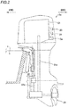
FIG. 2 is a side view illustrating the structure of an outboard motor according to a preferred embodiment. -
FIG. 3 is a block diagram showing the structure of a marine vessel according to a preferred embodiment. -
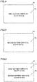
FIG. 4 is a diagram showing an example of a message image according to a preferred embodiment. -
FIG. 5 is another diagram showing an example of a message image according to a preferred embodiment. -
FIG. 6 is still another diagram showing an example of a message image according to a preferred embodiment. -
FIG. 7 is a diagram showing a display of detection results according to a preferred embodiment. -
FIG. 8 is a flowchart showing a control process of a marine vessel control system according to a preferred embodiment. - Preferred embodiments are hereinafter described with reference to the drawings.
- The structure of a
marine vessel 100 according to preferred embodiments is now described with reference toFIGS. 1 to 7 . In the figures, arrow FWD represents the forward movement direction of themarine vessel 100, and arrow BWD represents the reverse movement direction of themarine vessel 100. - As shown in
FIG. 1 , themarine vessel 100 includes a hull 1,outboard motors vessel control system 3. That is, themarine vessel 100 is an outboard motor boat. Furthermore, the marinevessel control system 3 is a power supply system that supplies power to theoutboard motors outboard motors vessel control system 3 is an example of a "marine power supply system". - The
outboard motors outboard motors FIG. 2 , theoutboard motor 2a includes anengine 21, anelectric motor 22, apropeller 23, an engine ECU (electronic control unit) 24, and astarter motor 25. The structure of theoutboard motor 2b is the same as that of theoutboard motor 2a. Thepropeller 23 is an example of a "propulsion generator". Thestarter motor 25 is an example of a "starter". - The
engine 21 drives thepropeller 23. Specifically, theengine 21 is an internal combustion engine driven by combustion of gasoline, light oil, or the like. Theengine 21 is connected to thepropeller 23 via adrive shaft 21a, etc. A driving force (rotational force) is transmitted theengine 21 to thepropeller 23 such that thepropeller 23 rotates, and the marine vessel 100 (hull 1) is propelled. - The
electric motor 22 drives thepropeller 23. Theelectric motor 22 is a motor. Theelectric motor 22 provided in theoutboard motor 2a is driven using power from anelectric motor battery 34a described below. Theelectric motor 22 provided in theoutboard motor 2b is driven using power from anelectric motor battery 34b described below. Specifically, theelectric motor 22 provided in theoutboard motor 2a is driven using power converted by aninverter device 5a described below. Theelectric motor 22 provided in theoutboard motor 2b is driven using power converted by aninverter device 5b described below. Theelectric motor 22 is connected to thepropeller 23 via ashaft 22a, a propeller shaft, etc. A driving force (rotational force) is transmitted from theelectric motor 22 to thepropeller 23 such that thepropeller 23 rotates, and the marine vessel 100 (hull 1) is propelled. - The
propeller 23 is positioned in the water, and rotates to generate a propulsive force. - As shown in
FIG. 3 , theengine ECU 24 communicates with ahybrid controller 31 described below and theinverter device outboard motor engine ECU 24 transmits and receives information and command signals to and from thehybrid controller 31 and theinverter device engine ECUs 24 are connected to amain battery 35, and operate using power from themain battery 35. - The
starter motors 25 start theengines 21. Specifically, thestarter motors 25 are connected to themain battery 35, and are driven using power from themain battery 35. Thestarter motors 25 rotate (crank) crankshafts of theengines 21 based on commands from the engine ECUs 24 (hybrid controller 31). Theengines 21 are cranked by thestarter motors 25, fuel is supplied into theengines 21 by fuel suppliers (not shown), and the fuel in theengines 21 is ignited by igniters (not shown) to start theengines 21. Power is supplied from themain battery 35 to the fuel suppliers and the igniters. - The marine
vessel control system 3 includes thehybrid controller 31, adisplay 32, a marinevessel maneuvering unit 33, theelectric motor batteries main battery 35, ahouse battery 36,battery switches inverter devices hybrid controller 31 is an example of a "controller". Thedisplay 32 is an example of a "notifier". Theelectric motor batteries main battery 35 is an example of a "second battery" or a "third battery". Thus, in this embodiment themain battery 35 is provided to supply power to thestarter 25, and themain battery 35 is provided to supply power to apower conversion controller 52 described later. Alternatively, a second battery provided to supply power to thestarter 25 is provided separately from a third battery provided to supply power to thepower conversion controller 52. - The
hybrid controller 31, thedisplay 32, the marinevessel maneuvering unit 33, theelectric motor batteries main battery 35, thehouse battery 36, and thebattery switches display 32 is positioned in the vicinity of the marinevessel maneuvering unit 33, for example. Thedisplay 32 is provided at a position visually recognized by a user who operates the marinevessel maneuvering unit 33. On thedisplay 32, a gauge such as an engine speed is displayed. Theinverter device 5a is provided in theoutboard motor 2a. Theinverter device 5b is provided in theoutboard motor 2b. - The battery switches 4a and 4b are manually switched between on-states in which the
electric motor batteries electric motor batteries 34a and 33b are not used, respectively. - Specifically, the
battery switches electric motor battery 34a and theinverter device 5a and between theelectric motor battery 34b and theinverter device 5b, respectively. Thebattery switch 4a is rotated or moved by the user such that a state in which theelectric motor battery 34a and theinverter device 5a are conducted (theelectric motor battery 34a is used) and a state in which theelectric motor battery 34a and theinverter device 5a are shut off (theelectric motor battery 34a is not used) are switched. Furthermore, thebattery switch 4b is rotated or moved by the user such that a state in which theelectric motor battery 34b and theinverter device 5b are conducted (theelectric motor battery 34b is used) and a state in which theelectric motor battery 34b and theinverter device 5b are shut off (theelectric motor battery 34b is not used) are switched. - The
hybrid controller 31 is a control circuit that controls both driving of theengines 21 in theoutboard motors electric motors 22 in theoutboard motors hybrid controller 31 includes a processor such as a CPU to perform an arithmetic process. Specifically, thehybrid controller 31 is configured or programmed to perform a control to switch between an engine driving state in which thepropellers 23 are driven by theengines 21 and an electric motor driving state in which thepropellers 23 are driven by theelectric motors 22. Thehybrid controller 31 controls theoutboard motors marine vessel 100 travels at a low speed, and controls theoutboard motors marine vessel 100 travels at a high speed. - As shown in
FIGS. 4 to 6 , according to preferred embodiments, thedisplay 32 provides a notification indicating that at least one of thebattery switch battery switch hybrid controller 31. In other words, thehybrid controller 31 is configured or programmed to control thedisplay 32 to provide a notification indicating that at least one of thebattery switch battery switch - Specifically, as shown in
FIG. 4 , thedisplay 32 displays a message image P1, "first battery switch is in off-state", when thebattery switch 4a is in the off-state based on a command from thehybrid controller 31. As shown inFIG. 5 , thedisplay 32 displays a message image P2, "second battery switch is in off-state", when thebattery switch 4b is in the off-state based on a command from thehybrid controller 31. As shown inFIG. 6 , thedisplay 32 displays both the message images P1 and P2 when both thebattery switches hybrid controller 31. The message images P1 and P2 are examples of "message information". - According to preferred embodiments, the
hybrid controller 31 is configured or programmed to control thedisplay 32 to provide a notification indicating that at least one of thebattery switch engines 21 to start when power is supplied from themain battery 35 to thestarter motors 25 and when at least one of thebattery switch outboard motors engines 21 even when at least one of thebattery switch - As shown in
FIG. 3 , the marinevessel maneuvering unit 33 includes a remote control, for example. The marinevessel maneuvering unit 33 receives input operations by the user and transmits operation signals based on the received input operations to thehybrid controller 31. Thehybrid controller 31 controls the operation of theoutboard motors - The
electric motor battery 34a, theelectric motor battery 34b, themain battery 35, and thehouse battery 36 are separated from each other. Theelectric motor battery 34a supplies power to theelectric motor 22 via theinverter device 5a. Theelectric motor battery 34b supplies power to theelectric motor 22 via theinverter device 5b. Themain battery 35 supplies power to each of thestarter motors 25 that start theengines 21 of theoutboard motors house battery 36 supplies power to at least some devices (devices in a house) other than theelectric motors 22 and thestarter motors 25 among devices in themarine vessel 100. Theelectric motor batteries main battery 35, and thehouse battery 36 are lead storage batteries or lithium-ion batteries. - The
inverter devices electric motor batteries hybrid controller 31 or theengine ECUs 24 to supply the AC power to theelectric motors 22 of theoutboard motors inverter devices inverter device 5a is positioned between thebattery switch 4a and theelectric motor 22 of theoutboard motor 2a. Theinverter device 5b is positioned between thebattery switch 4b and theelectric motor 22 of theoutboard motor 2b. - The
inverter device 5a includes apower converter 51, aninverter controller 52, and astorage 53. The structure of theinverter device 5b is the same as that of theinverter device 5a. Theinverter controller 52 is an example of a "power conversion controller". - Each of the
power converters 51 includes a switching circuit. Each of thepower converters 51 converts DC power from thebattery switch outboard motor electric motor 22. - Each of the
inverter controllers 52 includes a microcomputer. Theinverter controllers 52 are configured or programmed to control the operation of thepower converters 51. Theinverter controller 52 provided in theoutboard motor 2a is configured or programmed to detect that thebattery switch 4a is in the off-state. Specifically, theinverter controller 52 detects that thebattery switch 4a is in an on-state based on theelectric motor battery 34a supplying power to the power converter 51 (a voltage being applied, for example), and detects that thebattery switch 4a is in the off-state based on theelectric motor battery 34a supplying no power to the power converter 51 (no voltage being applied, for example).
Each of thestorages 53 includes a non-volatile memory. Each of the storages 53 stores the date and time and information (detection result) indicating whether thebattery switch battery switch inverter controller 52. As shown inFIG. 7 , thehybrid controller 31 reads information in which the date and time and the detection result are associated with each other by accessing each of thestorages 53, and controls thedisplay 32 to display an image P3, which is the information in which the date and time and the detection result are associated with each other. - A method for controlling the
marine vessel 100 according to preferred embodiments is now described with reference toFIG. 8. FIG. 8 shows a flowchart of a control process in themarine vessel 100. The following control process is executed by thehybrid controller 31 and theinverter controllers 52. - In step S1, the
inverter controller 52 of theoutboard motor 2a acquires the detection result of whether or not thebattery switch 4a is in the off-state, and theinverter controller 52 of theoutboard motor 2b acquires the detection result of whether or not thebattery switch 4b is in the off-state. Then, the process advances to step S2. - In step S2, the
hybrid controller 31 determines whether or not at least one of thebattery switch battery switch battery switches - In step S3, at least one of the message image P1 indicating that the
battery switch 4a is in the off-state or the message image P2 indicating that thebattery switch 4b is in the off-state is displayed on thedisplay 32. Then, the process returns to step S1. - When power is supplied from the
main battery 35 to thestarter motors 25, theengines 21 are started even when at least one of the message image P1 or P2 is displayed. - In the structure according to the various preferred embodiments described above, the following advantageous effects are achieved.
- According to a preferred embodiment, the marine
vessel control system 3 includes thedisplay 32 to provide a notification indicating that at least one of thebattery switch battery switch display 32 notifies the user that at least one of thebattery switch outboard motors engines 21 and theelectric motors 22, traveling of themarine vessel 100 without the user being aware that thebattery switch - According to a preferred embodiment, the marine
vessel control system 3 includes thehybrid controller 31 configured or programmed to control thedisplay 32 to provide a notification indicating that at least one of thebattery switch battery switch display 32 is easily controlled using thehybrid controller 31. - According to a preferred embodiment, the
hybrid controller 31 is configured or programmed to control thedisplay 32 to provide a display indicating that at least one of thebattery switch battery switch battery switch display 32. - According to a preferred embodiment, the
hybrid controller 31 is configured or programmed to control thedisplay 32 to display at least one of the message image P1 or P2 indicating that at least one of thebattery switch battery switch battery switch display 32 and reading the message content. - According to a preferred embodiment, the
hybrid controller 31 is configured or programmed to perform a control to switch between the engine driving state in which thepropellers 23 are driven by theengines 21 and the electric motor driving state in which thepropellers 23 are driven by theelectric motors 22. Accordingly, thehybrid controller 31 functions as a controller for a hybrid system configured or programmed to perform a control to switch between the engine driving state and the electric motor driving state, and also functions as a controller configured or programmed to control thedisplay 32. Consequently, as compared with a case in which the controller for the hybrid system is separated from the controller configured or programmed to control thedisplay 32, a complex structure of themarine vessel 100 including the marinevessel control system 3 is significantly reduced or prevented. - According to a preferred embodiment, the marine
vessel control system 3 includes thestarter motors 25 connected to theengines 21 to start theengines 21, and themain battery 35 provided separately from theelectric motor batteries starter motors 25. Furthermore, thehybrid controller 31 is configured or programmed to control thedisplay 32 to provide a notification indicating that at least one of thebattery switch engines 21 to start when power is supplied from themain battery 35 to thestarter motors 25 and when at least one of thebattery switch engines 21 are started even when the notification indicating that at least one of thebattery switch battery switch engines 21 are started when the user desires to start theengines 21. - According to a preferred embodiment, the marine
vessel control system 3 includes theinverter devices battery switches electric motors 22 to detect that at least one of thebattery switch battery switch display 32 based on the detection results detected by theinverter controllers 52. - According to a preferred embodiment, the marine
vessel control system 3 includes thepower converters 51 to convert the DC power from thebattery switches electric motors 22, and theinverter controllers 52 configured or programmed to control the operation of thepower converters 51. Accordingly, it is not necessary to provide a dedicated controller to detect that at least one of thebattery switch vessel control system 3 is significantly reduced or prevented, and a complex structure of the marinevessel control system 3 is significantly reduced or prevented. - According to a preferred embodiment, the marine
vessel control system 3 includes themain battery 35 provided separately from theelectric motor batteries inverter controllers 52. Accordingly, even when power is not supplied from theelectric motor batteries inverter controllers 52, theinverter controllers 52 detect that at least one of thebattery switch main battery 35. - According to a preferred embodiment, the marine
vessel control system 3 includes thestorages 53 to store the detection results detected by theinverter controllers 52. Accordingly, the user or a maintenance worker is able to retroactively confirm the detection results stored in thestorages 53. - According to a preferred embodiment, the marine
vessel control system 3 includes theelectric motor batteries battery switches display 32 provides a notification indicating that at least one of thebattery switch battery switches battery switches battery switch battery switch - In the control method according to the various preferred embodiments described above, the following advantageous effects are achieved.
- According to a preferred embodiment, even when power is supplied to the
outboard motors engines 21 and theelectric motors 22, traveling of themarine vessel 100 without the user being aware that thebattery switch vessel control system 3. - The preferred embodiments described above are illustrative for present teaching but the present teaching also relates to modifications of the preferred embodiments.
- For example, while the marine vessel is preferably an outboard motor boat in preferred embodiments described above, the present teaching is not restricted to this. That is, the marine vessel may alternatively be a marine vessel other than an outboard motor boat. For example, the marine vessel may be a marine vessel including an inboard motor(s), an inboard-outboard motor(s), or a jet propulsion device(s).
- While the main battery, the electric motor batteries, and the house battery are preferably provided in the hull in preferred embodiments described above, the present teaching is not restricted to this. That is, at least one of the main battery, the electric motor batteries, or the house battery may alternatively be provided in the outboard motors.
- While power is preferably supplied from the electric motor batteries only to the electric motors via the inverter devices in preferred embodiments described above, the present teaching is not restricted to this. That is, power may alternatively be supplied from the electric motor batteries to other devices in addition to the electric motors.
- While two battery switches are preferably provided in preferred embodiments described above, the present teaching is not restricted to this. That is, one common battery switch may alternatively be provided for a plurality of electric motor batteries, or three or more battery switches may alternatively be provided.
- While the display preferably provides a notification indicating that the battery switch is in the off-state in preferred embodiments described above, the present teaching is not restricted to this. For example, a sound output may alternatively be provided in the marine vessel, and the sound output may alternatively provide a notification indicating that the battery switch is in the off-state.
- While the display preferably displays the message image indicating that the battery switch is in the off-state in preferred embodiments described above, the present teaching is not restricted to this. For example, the display may alternatively display a warning light indicating that the battery switch is in the off-state without using a character image.
- While the hybrid controller preferably controls the display as a notifier in preferred embodiments described above, the present teaching is not restricted to this. For example, the marine vessel control system may alternatively include a controller dedicated for the display as a notifier separately from the hybrid controller.
- While each of the inverter controllers preferably detects that the battery switch is in the off-state in preferred embodiments described above, the present teaching is not restricted to this. For example, a detector may alternatively be provided to detect that the battery switch is in the off-state by detecting a voltage or current in a path between the battery switch and the inverter device, or a detector may alternatively be provided to detect that the battery switch is in the off-state by detecting the state (such as the rotation angle or position) of the battery switch.
- While power is preferably supplied from the main battery to the inverter controllers in preferred embodiments described above, the present teaching is not restricted to this. For example, power may alternatively be supplied from the house battery to the inverter controllers.
- While the storages are preferably provided in the inverter devices in preferred embodiments described above, the present teaching is not restricted to this. For example, the storages may alternatively be provided in the hull.
Claims (15)
- A marine power supply system (3) configured to supply power to a marine propulsion unit (2a, 2b) including a propulsion generator (23) configured to generate a propulsive force to propel a marine vessel (100), an engine (21) configured to drive the propulsion generator (23), and an electric motor (22) configured to drive the propulsion generator (23), the marine power supply system (3) comprising:a first battery (34a, 34b) configured to supply power to the electric motor (22);a battery switch (4a, 4b) configured to be manually switched by a user between an on-state in which the first battery (34a, 34b) is used to supply power to the electric motor (22) and an off-state in which the first battery (34a, 34b) is not used to supply power to the electric motor (22); and
;a notifier (32) configured to provide a notification to the user indicating that the battery switch (4a, 4b) is in the off-state when the battery switch (4a, 4b) is in the off-state. - The marine power supply system (3) according to claim 1, further comprising:
a controller (31) configured or programmed to control the notifier (32) to provide the notification indicating that the battery switch (4a, 4b) is in the off-state when the battery switch (4a, 4b) is in the off-state. - The marine power supply system (3) according to claim 2, wherein the notifier (32) includes a display (32); and
the controller (31) is configured or programmed to control the display (32) to provide a display indicating that the battery switch (4a, 4b) is in the off-state when the battery switch (4a, 4b) is in the off-state. - The marine power supply system (3) according to claim 3, wherein the controller (31) is configured or programmed to control the display (32) to display message information (P1, P2) indicating that the battery switch (4a, 4b) is in the off-state when the battery switch (4a, 4b) is in the off-state.
- The marine power supply system (3) according to any one of claims 2 to 4, wherein the controller (31) is configured or programmed to perform a control to switch between an engine driving state in which the propulsion generator (23) is driven by the engine (21) and an electric motor driving state in which the propulsion generator (23) is driven by the electric motor (22).
- The marine power supply system (3) according to claim 5, further comprising:a starter (25) connected to the engine (21) to start the engine (21); anda second battery (35) provided separately from the first battery (34a, 34b) and configured to supply power to the starter (25); whereinthe controller (31) is configured or programmed to control the notifier (32) to provide the notification indicating that the battery switch (4a, 4b) is in the off-state and to control the engine (21) to start when power is supplied from the second battery (35) to the starter (25) and when the battery switch (4a, 4b) is in the off-state.
- The marine power supply system (3) according to any one of claims 1 to 6, further comprising:
a detector (5a, 5b) provided between the battery switch (4a, 4b) and the electric motor (22) to detect that the battery switch (4a, 4b) is in the off-state. - The marine power supply system (3) according to claim 7, further comprising:a power converter (51) configured to convert DC power from the battery switch (4a, 4b) into AC power to supply the AC power to the electric motor (22); anda power conversion controller (52) configured or programmed to control operation of the power converter (51) and to also serve as the detector (5a, 5b).
- The marine power supply system (3) according to claim 8, further comprising:
a third battery (35) provided separately from the first battery (34a, 34b) and configured to supply power to the power conversion controller (52). - The marine power supply system (3) according to any one of claims 7 to 9, further comprising:
a storage (53) configured to store a detection result detected by the detector (5a, 5b). - The marine power supply system (3) according to any one of claims 1 to 10, wherein the first battery (34a, 34b) includes a plurality of first batteries;
the battery switch (4a, 4b) includes a plurality of battery switches; and
the notifier (32) is configured to provide a notification indicating that at least one of the plurality of battery switches is in the off-state when the at least one of the plurality of battery switches is in the off-state. - A method for controlling a marine power supply system (3) configured to supply power to a marine propulsion unit (2a, 2b) including a propulsion generator (23) configured to generate a propulsive force to propel a marine vessel (100), an engine (21) configured to drive the propulsion generator (23), an electric motor (22) configured to drive the propulsion generator (23), a first battery (34a, 34b) configured to supply power to the electric motor (22), and a battery switch (4a, 4b) configured to be manually switched by a user between an on-state in which the first battery (34a, 34b) is used to supply power to the electric motor (22) and an off-state in which the first battery (34a, 34b) is not used to supply power to the electric motor (22); the method comprising:acquiring that the battery switch (4a, 4b) is in the on-state or in the off-state; andproviding a notification to the user indicating that the battery switch (4a, 4b) is in the off-state when the battery switch (4a, 4b) is in the off-state based on acquiring that the battery switch is in the off-state.
- The method for controlling the marine power supply system (3) according to claim 12, wherein the providing of the notification includes providing a display (32) indicating that the battery switch (4a, 4b) is in the off-state when the battery switch (4a, 4b) is in the off-state.
- The method for controlling the marine power supply system (3) according to claim 13, wherein the providing of the notification includes displaying message information (P1, P2) indicating that the battery switch (4a, 4b) is in the off-state when the battery switch (4a, 4b) is in the off-state.
- The method for controlling the marine power supply system (3) according to any one of claims 12 to 14, wherein the marine power supply system (3) further comprises:a starter (25) connected to the engine (21) to start the engine (21); anda second battery (35) provided separately from the first battery (34a, 34b) to supply power to the starter (25); andthe providing of the notification includes providing the notification indicating that the battery switch (4a, 4b) is in the off-state and starting the engine (21) when power is supplied from the second battery (35) to the starter (25) and when the battery switch (4a, 4b) is in the off-state.
Applications Claiming Priority (1)
| Application Number | Priority Date | Filing Date | Title |
|---|---|---|---|
| JP2020058945A JP2021154946A (en) | 2020-03-27 | 2020-03-27 | Marine power supply system, and control method of marine power supply system |
Publications (1)
| Publication Number | Publication Date |
|---|---|
| EP3895981A1 true EP3895981A1 (en) | 2021-10-20 |
Family
ID=75223165
Family Applications (1)
| Application Number | Title | Priority Date | Filing Date |
|---|---|---|---|
| EP21164874.6A Pending EP3895981A1 (en) | 2020-03-27 | 2021-03-25 | Marine power supply system and method for controlling marine power supply system |
Country Status (3)
| Country | Link |
|---|---|
| US (1) | US12403996B2 (en) |
| EP (1) | EP3895981A1 (en) |
| JP (1) | JP2021154946A (en) |
Families Citing this family (6)
| Publication number | Priority date | Publication date | Assignee | Title |
|---|---|---|---|---|
| JP2021160665A (en) * | 2020-04-02 | 2021-10-11 | ヤマハ発動機株式会社 | Device and method of controlling vessel battery, and vessel |
| JP7525289B2 (en) * | 2020-04-16 | 2024-07-30 | ヤマハ発動機株式会社 | Outboard motor, outboard motor control method and ship |
| JP2022117839A (en) * | 2021-02-01 | 2022-08-12 | ヤマハ発動機株式会社 | Power supply system for ship |
| JP2025020881A (en) * | 2023-07-31 | 2025-02-13 | ヤンマーホールディングス株式会社 | Ships |
| EP4574640A1 (en) * | 2023-12-22 | 2025-06-25 | Volvo Penta Corporation | A marine drive unit |
| US12558991B1 (en) * | 2024-01-25 | 2026-02-24 | Brunswick Corporation | Power panel assemblies for marine vessels |
Citations (4)
| Publication number | Priority date | Publication date | Assignee | Title |
|---|---|---|---|---|
| US20100248560A1 (en) * | 2009-03-31 | 2010-09-30 | Yamaha Hatsudoki Kabushiki Kaisha | Marine vessel propulsion system and marine vessel |
| JP2011051416A (en) * | 2009-08-31 | 2011-03-17 | Yamaha Motor Co Ltd | Small vessel |
| JP2017218016A (en) | 2016-06-07 | 2017-12-14 | ヤマハ発動機株式会社 | Ship propulsion machine |
| EP3613663A1 (en) * | 2018-08-23 | 2020-02-26 | Yamaha Hatsudoki Kabushiki Kaisha | Hybrid type vessel propulsion apparatus |
Family Cites Families (8)
| Publication number | Priority date | Publication date | Assignee | Title |
|---|---|---|---|---|
| US3602181A (en) * | 1969-06-20 | 1971-08-31 | Garrett H Harris | Outboard motor steering control |
| JP3687753B2 (en) * | 1995-02-02 | 2005-08-24 | ヤマハマリン株式会社 | Marine Engine Operation Control Device |
| JPH11266502A (en) | 1998-03-17 | 1999-09-28 | Mitsubishi Motors Corp | Power display for electric vehicles |
| JP2013039888A (en) | 2011-08-18 | 2013-02-28 | Suzuki Motor Corp | Electric outboard motor |
| US8944865B1 (en) * | 2013-01-24 | 2015-02-03 | Brunswick Corporation | Water sensing interlock systems and methods for hybrid marine vessels |
| JP6671223B2 (en) * | 2016-04-12 | 2020-03-25 | ヤマハ発動機株式会社 | Ship power supply system |
| WO2020141513A2 (en) * | 2018-12-31 | 2020-07-09 | Polarity Mobility Av Ltd. | Evtol aircraft |
| US12140613B2 (en) * | 2019-11-05 | 2024-11-12 | Tmeic Corporation | Open-phase detection circuit and power conversion apparatus |
-
2020
- 2020-03-27 JP JP2020058945A patent/JP2021154946A/en active Pending
-
2021
- 2021-03-25 US US17/211,984 patent/US12403996B2/en active Active
- 2021-03-25 EP EP21164874.6A patent/EP3895981A1/en active Pending
Patent Citations (5)
| Publication number | Priority date | Publication date | Assignee | Title |
|---|---|---|---|---|
| US20100248560A1 (en) * | 2009-03-31 | 2010-09-30 | Yamaha Hatsudoki Kabushiki Kaisha | Marine vessel propulsion system and marine vessel |
| JP2011051416A (en) * | 2009-08-31 | 2011-03-17 | Yamaha Motor Co Ltd | Small vessel |
| JP2017218016A (en) | 2016-06-07 | 2017-12-14 | ヤマハ発動機株式会社 | Ship propulsion machine |
| EP3613663A1 (en) * | 2018-08-23 | 2020-02-26 | Yamaha Hatsudoki Kabushiki Kaisha | Hybrid type vessel propulsion apparatus |
| EP3613663B1 (en) * | 2018-08-23 | 2021-02-24 | Yamaha Hatsudoki Kabushiki Kaisha | Hybrid type vessel propulsion apparatus |
Also Published As
| Publication number | Publication date |
|---|---|
| JP2021154946A (en) | 2021-10-07 |
| US20210300516A1 (en) | 2021-09-30 |
| US12403996B2 (en) | 2025-09-02 |
Similar Documents
| Publication | Publication Date | Title |
|---|---|---|
| US12403996B2 (en) | Marine power supply system and method for controlling marine power supply system | |
| JP4421344B2 (en) | Ship drive control method | |
| US12249858B2 (en) | Marine propulsion system and marine power supply system including a plurality of batteries | |
| JP2023115833A (en) | Ship control system and control method | |
| EP3895979B1 (en) | Marine power supply system | |
| EP3971079A1 (en) | Marine propulsion system and outboard motor | |
| JP4102220B2 (en) | Hybrid system | |
| US7331834B2 (en) | Outboard motor | |
| US12600451B2 (en) | Marine propulsion system, outboard motor, and marine vessel | |
| JP4288516B2 (en) | Marine hybrid propulsion system | |
| EP3868645B1 (en) | Marine propulsion system and control method | |
| JP2021138230A (en) | Ship propulsion system and control method | |
| US20210309326A1 (en) | Control system for marine propulsion device, control method for the same, and marine vessel | |
| US20250042526A1 (en) | Watercraft propulsion system, and watercraft | |
| US20240092469A1 (en) | Marine propulsion system, vessel, and control method | |
| US11530676B2 (en) | Power supply system for watercraft | |
| EP3875361B1 (en) | Marine propulsion system and control method | |
| EP3590822A1 (en) | Marine propulsion system and ship | |
| US11738845B2 (en) | Operation device in ship propulsion system | |
| US12515775B2 (en) | System and method of hybrid marine propulsion | |
| EP4534404B1 (en) | Title of invention: method for controlling ship, ship control program, ship control system, and ship | |
| JP2010241207A (en) | Ship propulsion system and ship | |
| JP2025079395A (en) | Propulsion system, ship and control method | |
| JP2023152162A (en) | Ship control system and control method | |
| JPS61163093A (en) | Remote controller for propeller of ship |
Legal Events
| Date | Code | Title | Description |
|---|---|---|---|
| PUAI | Public reference made under article 153(3) epc to a published international application that has entered the european phase |
Free format text: ORIGINAL CODE: 0009012 |
|
| STAA | Information on the status of an ep patent application or granted ep patent |
Free format text: STATUS: THE APPLICATION HAS BEEN PUBLISHED |
|
| AK | Designated contracting states |
Kind code of ref document: A1 Designated state(s): AL AT BE BG CH CY CZ DE DK EE ES FI FR GB GR HR HU IE IS IT LI LT LU LV MC MK MT NL NO PL PT RO RS SE SI SK SM TR |
|
| B565 | Issuance of search results under rule 164(2) epc |
Effective date: 20210916 |
|
| STAA | Information on the status of an ep patent application or granted ep patent |
Free format text: STATUS: REQUEST FOR EXAMINATION WAS MADE |
|
| 17P | Request for examination filed |
Effective date: 20220414 |
|
| RBV | Designated contracting states (corrected) |
Designated state(s): AL AT BE BG CH CY CZ DE DK EE ES FI FR GB GR HR HU IE IS IT LI LT LU LV MC MK MT NL NO PL PT RO RS SE SI SK SM TR |
|
| STAA | Information on the status of an ep patent application or granted ep patent |
Free format text: STATUS: EXAMINATION IS IN PROGRESS |
|
| 17Q | First examination report despatched |
Effective date: 20230525 |