EP3895484B1 - Netzwerkunterstützte positionsmessungen - Google Patents
Netzwerkunterstützte positionsmessungen Download PDFInfo
- Publication number
- EP3895484B1 EP3895484B1 EP18830765.6A EP18830765A EP3895484B1 EP 3895484 B1 EP3895484 B1 EP 3895484B1 EP 18830765 A EP18830765 A EP 18830765A EP 3895484 B1 EP3895484 B1 EP 3895484B1
- Authority
- EP
- European Patent Office
- Prior art keywords
- location server
- base station
- target device
- reference device
- information
- Prior art date
- Legal status (The legal status is an assumption and is not a legal conclusion. Google has not performed a legal analysis and makes no representation as to the accuracy of the status listed.)
- Active
Links
Images






Classifications
-
- H—ELECTRICITY
- H04—ELECTRIC COMMUNICATION TECHNIQUE
- H04W—WIRELESS COMMUNICATION NETWORKS
- H04W64/00—Locating users or terminals or network equipment for network management purposes, e.g. mobility management
-
- H—ELECTRICITY
- H04—ELECTRIC COMMUNICATION TECHNIQUE
- H04W—WIRELESS COMMUNICATION NETWORKS
- H04W4/00—Services specially adapted for wireless communication networks; Facilities therefor
- H04W4/02—Services making use of location information
- H04W4/023—Services making use of location information using mutual or relative location information between multiple location based services [LBS] targets or of distance thresholds
Definitions
- Embodiments of the present invention refer to a method for determining the position of a target device within a communication network. Further embodiments refer to a corresponding target device comprising a receiving unit and a radio frequency (RF) measurement unit, to a base station or a location server comprising a selector and a transmitter, and to a reference device with configurable properties. Further embodiments refer to a system comprising a base station or a location server, a target device, and a reference device for determining the position of a target device within a communication network.
- RF radio frequency
- Narrowband Internet of Things (NB-IOT) devices are only supported with an observed time difference of arrival (OTDOA) positioning method which does not achieve good performance and sufficient accuracy, and it requires a time synchronization among the base stations.
- OTDOA time difference of arrival
- the document further discloses the usage of positioning reference signals (PRS) to allow the UE to perform proper timing (ranging) measurements of signals from multiple cells to improve OTDOA positioning performance.
- PRS positioning reference signals
- the document also introduces 'PRS muting', that is, eNodeBs can be configured for time based blanking. When strong PRS signal is muted, the weak PRS signals from neighbour cells are more easily detected by the user equipment.
- LPWAN low power wide area network
- NB-IOT low power wide area network
- Fingerprinting, continuous power detection of other nodes during reception or transmissions at higher rates are power-consuming options.
- LPWAN devices, like NB-IOT cannot directly communicate with each other.
- An aspect provides a method for determining the position of a target device within a communication network. The method comprises the following steps:
- IOT devices A multitude of IOT devices is spread over the coverage area of the communication network.
- the low cost of the IOT devices makes the deployment of IOT devices and/or beacons, for supporting or for providing positioning applications, a very attractive solution.
- Stationary IOT devices or moving IOT devices with positioning sensors can be used as reference devices for enhancing the capability to determine the position of a mobile target device within the communication network.
- a mobile target device which can detect some characteristics of transmissions of neighboring reference devices, is informed by the base station or by the location server, where the signals are expected to be in time and in frequency. The target device does not explicitly need to know which devices are transmitting.
- the measurement unit of the target device performs power detection based on the information received from the base station or from the location server. These can range from low complexity detection of simple parameters, like RF power, to full reception and/or decoding. By this process, additional measurement values dependent on the distance between the target device and the reference devices become available.
- the method further comprises a step wherein a single base station or multiple base stations or the location server performs a coarse estimation of the position of the target device.
- the target device, the base station or the location server requests, as a first step, the position of the target device.
- the base station or the location server can determine the position of the target device coarsely.
- the coarse estimation is, for example, done based on rough timing measurements (timing advance), cell ID information and can be combined with a receive signal strength indication (RSSI) or, if supported, through an observed time difference of arrival (OTDOA) approach.
- the coarse position of the target device defines a pool of reference devices whose transmitted signals can be detected by the target device.
- further position calculations are based on the coarse position of the target device.
- the method further comprises a step, in which the base station or the location server chooses a reference device from the pool of devices within a detectable range from the target device.
- the choice of which reference devices to use for assistance can be based on the transmission time, as low power IOT devices do not transmit very often, and/or based on the position of the reference devices and/or the type of the application of the target device to be located (for example, bikes need faster measurements than key tracking). Choosing a reference device which is closer to the estimated position of the target device is reducing the measurement uncertainty of the position of the target device.
- the method further comprises that the base station or the location server requests information about the capabilities and/or the configurations of the target device from the target device.
- the target device provides the information about its capabilities and configurations for the base station and/or for the location server.
- the base station or the location server requests information about the capabilities and/or the configurations of the reference device from the reference device.
- the reference device provides the information about its capabilities and configurations for the base station or for the location server.
- NB-IOT devices like the target device and/or the reference device, can only communicate with the communication network mainly through the serving base station (eNB). That means that within this communication, reference signals are exchanged in uplink, i.e. device transmits to eNB, and in downlink, i.e. eNB transmits to device, such as sounding reference signal (SRS), synchronization signals or other dedicated signaling.
- SRS sounding reference signal
- the base station and/or the location server takes the role of collecting information from and/or configuring the target device and/or the reference device, allowing an indirect communication between the target device and the reference devices.
- the method comprises a step where the base station or the location server triggers the chosen reference device to transmit a signal and/or the base station or the location server is informed on a scheduled transmission by the reference device or by the location server or by the base station.
- the base station and/or a location server makes a set of hypotheses allowing the target device to possibly narrow down the uncertainty region.
- the base station or the location server either triggers the reference device or has the knowledge of the transmitting time and frequency allocation of the reference device.
- the base station or the location server sends information to the target device about the transmitting time and frequency allocation of the reference device and/or when the reference device was triggered by the base station or the location server. This information allows the target device to measure the power at determined time intervals and/or when the reference device is triggered by the base station or the location server. The result of the measurement can be used to enhance the accuracy and/or reduce the uncertainty achieved in the coarse positioning estimation.
- the method comprises that the base station or the location server sends information to the target device about the scheduled transmission and/or a frequency of the chosen reference device.
- the positioning target device is informed by the base station or location server of the communication network about where the signals are expected to be in time and in frequency.
- the target device does not even explicitly need to know which devices, with which device IDs, are transmitting.
- a target device A is informed that three signals, corresponding to three reference devices, are transmitted at time t1, t2 and t3 with the transmission frequencies of the reference devices respectively.
- the base station or the location server informs the target device for example over an LTE positioning protocol (LPP) about the time, for example in subframes or in other time units, of the first scheduled or expected reference device transmission.
- LTP LTE positioning protocol
- the base station or the location server can be configured to inform the target device about the timing information of the reference device in the communication network relative to other reference devices.
- the method comprises that the base station or the location server indicates a search window to find a transmitted signal of the reference device in order to perform the RF measurement.
- the base station or the location server assists the target device to efficiently find the transmitted signals. Otherwise, the target device will have to search for the signal over time which adds undesired complexity for low power devices.
- the method further comprises that the target device performs RF measurements on transmitted signals of the reference devices when the reference device is triggered and/or based on the information, about the transmitting time and frequency of the reference device, received from the base station or the location server.
- a measurement unit of the positioning target device performs power detection and obtains information about the received signals strength indication (RSSI) and/or about the signal noise ratio (SNR).
- RSSI received signals strength indication
- SNR signal noise ratio
- the target device treats the reference devices as a source, thus an application of a sidelink protocol is not needed.
- the method comprises that the base station or the location server requests measurement results of the RF measurement from the target device.
- the target device is providing measurement results and/or a time stamp of the RF measurement for the base station or for the location server.
- Another option is that the target device reports measurement results and/or a time stamp of the RF measurement to the base station or to the location server automatically, without a request from the base station of from the location server.
- Reporting the results of the RF measurements allows more power efficient target devices because the more power consuming calculations could be performed by the base station and/or the location server.
- the method further comprises a step, where the position of the target device is calculated based on the results of the RF measurements. Based on this calculation and based on the former coarse position estimation, a higher level of position accuracy could be reached and respectively the uncertainty region of the position of the target device could be narrowed down.
- the method comprises that the base station or the location server allocates and/or deallocates one or more reference devices in time.
- the base station or the location server can further allocate nearby reference devices. Repeating the measurements by using more reference devices can increase the accuracy of the position of the target devices and/or detect the movement of the target device.
- the movement of the target device can, for example, be detected by a difference between the measurement results of the RF measurements (e.g. RSSI) taken from the same reference device at different times.
- An aspect provides a system, comprising a base station or a location server, a target device and one or more reference devices for performing the method described above. Elements of the system will be explained below.
- a base station comprises a selector for selecting one or more reference devices, formed by IOT devices.
- the base station further comprises a transmitter configured to transmit information about transmitting time and frequency allocation of the reference device to a target device.
- the base station is configured to configure the properties or properties of period and/or power of the reference device.
- a location server comprises a selector for selecting one or more reference devices, formed by IOT devices.
- the location server further comprises a transmitter configured to transmit information about transmitting time and frequency allocation of the reference device to a target device.
- the location server is configured to identify whether the reference device is available and/or is capable of supporting the target device.
- the location server is further configured to configure the properties or properties of period and/or power of the reference device.
- the target device can perform an RF measurement in order to obtain a measurement value dependent on a distance between the target device and the selected reference device.
- the base station or the location server is also configured to inform the target device about where the signals are expected to be in time and frequency.
- a base station or a location server is configured to perform a coarse estimation of the position of the target device.
- the serving base station can, however, not determine the position accurately enough.
- the coarse estimation is done, for example, based on rough timing measurements (like timing advance), on cell ID information and can be combined with the RSSI measurements or if supported through the OTDOA approach.
- the coarse position estimation could be used as a base for more accurate position calculations and for determining a pool of reference devices within a detectable range from the target device.
- the selector of the base station or of the location server is configured to choose the reference device from a pool of devices within a detectable range from the target device. Choosing the right reference devices is necessary for a more accurate calculation of the position of the target device.
- a detectable reference device i.e. the transmitted signal of the reference device is detectable at the target device, is a minimum requirement for an RF measurement. Choosing a closer reference device also means RF measurements are more accurate, which leads to a more accurate target device position calculation.
- the base station or the location server is configured to trigger the chosen reference device to transmit a signal and/or to send information to the target device about the transmitting time and frequency of the chosen reference device.
- NB-IOT devices can only communicate with each other in the communication network mainly through the base station. Providing information about the time and frequency allocation of the signal transmission to the target device removes the undesired complexity of searching the transmitted signal of the reference device.
- the transmitted reference signal could be triggered by the base station or the location server or it could be a timely scheduled transmission of the reference device.
- a base station or a location server is configured to calculate the position of the target device. The calculation is based on the coarse positioning estimation which is enhanced by the results of the RF measurements of the target device. After the calculation the position of the target device has a better accuracy and/or a smaller measurement uncertainty.
- the target device which comprises a receiving unit for receiving information from the base station or from the location server about transmitting time and frequency allocation of the reference device, formed by an IOT device, within the communication network.
- the target device further comprises an RF measurement unit for expecting and /or acquiring a signal transmitted by the reference device and for performing RF measurements by the use of the information, in order to obtain a measurement value dependent on a distance between the target device and the reference device.
- the target device is informed by the base station or the location server of the communication network about where the signals are expected to be in time and in frequency.
- the target device treats the reference device as a source. With the use of the information about time and frequency, the target device is expecting the signal transmitted by the reference device without applying a sidelink protocol.
- the measurement unit of the target device performs, for example, a power detection and obtains, for example, RSSI and/or signal noise ratio values. As these values are dependent on the distance between the target device and the reference device, they are used in the position calculation of the target device in order to improve the capability and the accuracy to determine the position of the target device within the communication network.
- the RF measurement unit is integrated into the receiving unit or implemented as a separate RF detector.
- TDD Time division duplex
- FDD frequency division duplex
- the receiving and transmitting frequency are the same hence the NB-IOT is in principle capable of performing all the measurements mentioned above on the signals transmitted by the reference devices, such as the synchronization reference signals.
- the same principle can be applied, but only if the target device is able to receive the carrier frequencies used by the reference device for uplink transmission.
- Low power RF detectors are used in case the target device does not have a receiving unit or the FDD operation mode does not support such measurements. Low power RF detectors are allowing NB-IOT devices without RF measurement capabilities to perform RF measurements.
- a target device is configured to use a search window to find a transmitted signal of the reference device.
- the base station or the location server assist the target device to efficiently find a transmitted signal by providing timing information of the search window.
- the search window can, for example, be applied for a reference signal time difference (RSTD) measurement according to the technical specification (TS) 36.355 for OTDOA positioning.
- RSTD reference signal time difference
- the target device can use the period information, such as frame ID and the pattern to track the next bursts of reference signals.
- the period information such as frame ID and the pattern to track the next bursts of reference signals.
- the search window value and an uncertainty of window size of the search window is determined by the base station or the location server based on for example, the timing advance information, the maximum frequency offset between the target device and the current reference device, the maximum timing misalignment between the target device, the reference device and the base station or the location server and the transmission time between the transmission from the reference device and the reception at the target device.
- These information, or a part of it, are provided to the target device by the base station or the location server. Without these information, the target device has to search for the signal emitted by the reference device over time which adds undesired complexity for low power devices.
- the main limitation of the search window could be that the time is related to the signal from a reference cell, for example in system frame number (SFN) unit, under the assumption that all base stations or location servers are synchronized.
- SFN system frame number
- the target device comprises a second sensor, like a speed, direction, etc. sensor, wherein the target device is configured to transmit the sensor information of the second sensor to the base station or to the location server.
- the base station or the location server in a communication network can optionally use a state of the art and/or other sensor information, like temperature, humidity (indication for indoor or outdoor), movement sensors that can provide further information for the base station or the location server, which can be used in the position calculation of the target device.
- a third component of this system described above is a reference device.
- the properties, like period, power, etc. of the reference device are configurable by the base station or by the location server.
- the reference device gets the necessary information for transmission which configures, for example, the sequence, set ID, period and power, or updates the needed parameters in case already configured.
- the base station or the location server controls the power, i.e. the knowledge of transmission power is given in communication system by reporting the reference power to the base station or the location server. It can be set, in case of the power needs to be increased or attenuated, based on the report of the target devices.
- the reference device is configured to periodically transmit information to the base station or to the location server and/or to be triggered by the base station or by the location server.
- the reference device can either be in radio resource control (RRC) connection mode and/or the reference device can be triggered on request by the base station or by the location server, for example with a wake-up signal or through the extended discontinuous reception (eDRX) mechanism, for transmission operations.
- RRC radio resource control
- eDRX extended discontinuous reception
- a reference device comprises a sensor for determining the position of the reference device or having a fixed position.
- Stationary IOT devices with a known position or IOT devices with positioning sensors are used to enhance the accuracy of the position calculation of the target device.
- Their known position is used as a reference position from which the target device is configured to measure and/or calculate its own distance or a value dependent on this distance.
- a reference device comprises a second sensor, like speed, direction, etc. sensor, wherein the reference device is configured to send sensor information of the second sensor to the base station or to the location server.
- the base station or the location server can optionally use state of the art and/or other sensor information, like temperature, humidity, position of the reference device, speed, direction, movement sensors in their calculations that can provide further information.
- Fig. 0 shows a communication network 100, or in other words, a system 100, comprising a target device 110, two reference devices 120a and 120b (or 310a and 310b), a base station 130 and a location server 440.
- the base station 130 is connected to the location server 440 and wirelessly connected to the target device 110 and the reference devices 120a and 120b.
- the target device 110 is a mobile device with an unknown position.
- the target device 110 is capable of receiving information 560 from the base station 130 or from the location server 440, and performing an RF measurement on the reference signals 540a and 540b.
- the reference IOT devices 120a and 120b may have different applications, for example parking metering, smart lighting, smart metering, monitoring in industrial or agricultural applications. These devices are, due to their use case, stationary or their location is known because the device is equipped with an extra positioning sensor, like a Global Navigation Satellite System (GNSS).
- GNSS Global Navigation Satellite System
- the reference devices 120a and 120b are capable of sending a reference signal 540a and 540b.
- the base station 130 or the location server 440 sends information 560 to the target device 110 about the transmit time and frequency of the reference device 120a or 120b within the communication network 100.
- the target device 100 receives the information 560 from the base station 130 or from the location server 440. By using the obtained information 560 the target device is waiting or searching for the reference signal 540a or 540b sent by the reference device 120a or 120b in order to perform RF measurements on the reference signal 540a or 540b.
- the RF measurement obtains a measurement value dependent on the distance 510a or 510b between the target device and reference device 120a or 120b, which sent the reference signal 540a or 540b measured by the target device 110.
- the obtained measurement value can be used in the position calculation of the target device 110, thus improving the accuracy and/or reducing the uncertainty.
- Fig. 1 shows a communication network 100, or in other words, a system 100, comprising target devices 110, reference devices 120 and base stations 130 within the cells 210 of the network 100.
- the target devices 110 and the reference devices 120 are wirelessly connected or can wirelessly communicate with the base stations 130, but they cannot communicate with each other.
- Reference devices 120 may have a well-known position, either because of their stationary operation or because of their integrated positioning sensor.
- Target devices 100 are, for example, moving mobile devices with unknown position.
- the present invention improves the position calculation of the target device 110. It is based on the idea that a multitude of reference devices 120 with known position are deployed all over the communication network 100 and can be used for enhancing the capability to determine the position of the target devices 110 within the communication network 100. By performing RF measurements on the reference signals transmitted by the reference devices 120, the target device can obtain a measurement value dependent on the distance between the target device and the reference device 120 which transmitted the measured reference signal.
- the first step of determining the position of a target device 110 is a course estimation of the position of the target device 110.
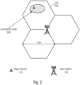
- Fig. 2 shows a part of the communication network, comprising a base station 130 and a target device 110 within one of cells 210. Fig. 2 does not show any reference devices 120.
- the position of the target device 110 is not accurate, it has a large uncertainty 220.
- the base station 130 can determine the position of the target device 110, however, with a large uncertainty 220.
- the rough estimation can be done based on, for example, a rough timing measurement, like timing advance, with the use of the ID of the cell 210, RSSI measurements or if supported through the OTDOA approach.
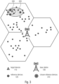
- Fig.3 illustrates a part of the communication network 100. It comprises a base station 130, a target device 110, a multitude of reference devices 120 and three chosen reference devices 310 within the cells 220. Fig.3 further illustrates the coarse uncertainty range 220 and the more accurate uncertainty range 320 of the position of the target device 110 before and after using the measurement values in the position calculation.
- the rough position of the target device 110 with a great uncertainty 220 is used to choose one or more reference devices 120.
- the chosen reference devices 310 are selected from a pool of reference devices 120 based, for example on the transmission time and/or on the position of the reference devices 120 and/or the type of the application of the target device 110.
- RF measurements are performed by the target device 110 on the reference signals transmitted by the reference devices 120 resulting a measurement value dependent on the distance between the chosen reference device 310 and the target device 110. Including these values into the position calculation of the target device 110 results in a more accurate target device position and/or reducing the rough uncertainty range 220 to a more accurate uncertainty range 320.
- Fig.4 illustrates a part of a communication system comprising a base station 130 connected to a location server 440, a target device 110, a multitude of reference devices and four chosen reference devices 310. Fig4 . Further shows reference signals 410, transmitted by chosen reference devices 310 and measured by the target device 110, and a report 450 on the measurement values transmitted by the target device 110 and received by the base station 130.
- the target device 110 After selecting some chosen reference devices 310 from a pool of reference devices 120 as illustrated in Fig.3 , the target device 110 performs RF measurements on the reference signals 410 transmitted by the chosen reference devices 310. The result of the RF measurements are transmitted as a report 450 to the base station 130 or to the location server 440 which is connected to the base station.
- Fig. 5 illustrates a part of a communication network, comprising a base station 130 connected to a location server 440 and wirelessly connected to a chosen reference device 310 and a target device 110.
- the target devices is capable to communicated with the base station 130 and/or with the location server 440 and capable of performing RF measurements on the reference signal 540 transmitted by the chosen reference device 310 within a distance 510.
- the chosen reference device 310 is capable of communicating with the base station 130 and/or with the location server 440 and is configurable by the base station 130 and/or the location server 440.
- the reference signal can be triggered by the base station 130 and/or by the location server 440.
- Fig. 5 shows an overview for the steps of a procedure gathering measurement values dependent on the distance 510 between the chosen reference device 310 and the target device 110.
- the chosen reference device 310 and the target device 110 can only communicate with each other mainly through the base station 130.
- the base station 130 is requesting 520 from the chosen reference device 310 and from the target device 110 information about the configuration and/or capabilities of the device itself.
- the chosen reference device 310 and the target device 110 provides the information about their capabilities and/or configurations for the base station 130 or to location server 440 connected to the base station 130.
- the base station 130 configures 530 the chosen reference device 310.
- the reference device 310 gets the necessary information for the transmission of the transmission signal 540 which configures the sequence, set ID, a period and power or updates the needed parameters in case already configured.
- the base station 130 or the location server 440 connected to the base station 130 controls the power of the signal 540 transmitted by the chosen reference device 310.
- the base station 130 or the location server 440 can optionally trigger 550 the chosen reference device 310 and sends assistance data 560 to the target device 110 about where the signal 540 of the chosen reference device 310 is expected to be in time and in frequency.
- the target device 110 will apply a search window 930 in order to find the signal 540.
- the target device 110 performs RF measurements on the signal 540 resulting a measurement value depending on the distance 510 between the chosen reference device 310 and the target device 110.
- the base station 130 or the location server 440 connected to the base station 130 is optionally requesting the measurement results 570 from the target device 110 or the target device 110 is automatically sending the measurement results 570 to the base station 130 or to the location server 440 connected to the base station 130.
- the configuration in Fig. 5 shows an overview for the proposed solution.
- the link between the base station 130 or the location server 440 connected to the base station 130 and the chosen reference device 310 is a new feature.
- the base station 130 or the location server 440 configured the chosen reference device 310, the reference device 310 is treated as a source from the perspective of the target device 110. That means that an application of a sidelink protocol is not needed.
- Fig. 6 shows a signaling procedure comprising a target device 110, a reference device 120, a base station 130, a location server 440 and the signaling between them.
- the location server 440 is identifying whether the target device 110 is capable of performing RF measurements 615 and requests the capabilities 610 of the target device 110. In response the target device 110 provides its own capabilities 620 to the location server 440.
- the location server 440 is identifying 635 whether a reference device 120 is available and/or is capable of supporting the target device 110.
- the location server 440 requests the capabilities 630 of the reference device 120.
- the reference device 120 provides its own capabilities 640 to the location server 440.
- the base station 130 configures 655 the selected reference device 120.
- the base station 130 provides configuration data 650 to the selected reference device 120.
- the reference device 120 provides a configuration completed feedback 660 back to the base station 130.
- the location server 440 provides assistance data 670 to the target device 110 in order to acquire measurements from the neighboring reference devices 120.
- the location server 440 requests 680 a measurement report from the target device 110 and in response the target device provides 690 the measurement report to the location server 440.
- Fig. 6 shows the main signaling procedure, the (due to the invention) extended LTE position protocol (LPP).
- LPP procedures between the location server 440 for example, enhanced serving mobile location center (E-SMLC) or secure user plane location (SUPL) service location protocol (SLP) usually consists of: capability transfer, assistance data transfer, location information transfer.
- E-SMLC enhanced serving mobile location center
- SUPL secure user plane location
- SLP service location protocol
- the procedure is extended to cover the suggested received power algorithm.
- the signaling between reference device and the location server and/or the base station is a new feature, represented by red arrows, which can be applied either through the radio resource control (RRC) or from higher layer.
- RRC radio resource control
- Fig. 6 shows an extended LTE positioning protocol where the green arrows represent the usual LTE positioning protocol and the red arrows represent the added steps.
- the properties of the reference is configurable by the base station or the location server.
- An exemplary configuration is illustrated in Fig. 7 .
- the reference device can either be in RRC connection mode or the reference device can be triggered on request, for example, with a wakeup signal or through the EDRX mechanism, for transmission operations.
- the reference device gets the necessary information for transmission, for example, which configures the sequence, set ID, period and power or updates the needed parameters in case already configured.
- the base station or the location server controls the power, that means the knowledge of transmission power is given in the system by reporting the power of the reference signal to the base station or the location server. It can be set in case of the signal power needs to be increased or attenuated based on the reports of the target device.
- the target device downloads 710 positioning configuration data 715.
- the configuration data 750 comprises a reference signal, allocated resources, period and power.
- the reference device sends 720 a reference signal 725 to the base station 130 or to the location server 440.
- the reference signal 725 is a sequence from an available set or a predefined sequence.
- the base station 130 or the location server 440 reports 730 back to the chosen reference device 310.
- the response 735 of the base station 130 or the location server 440 can be a request for reconfiguration 740, a request for power adjustment 750 or a success feedback 770.
- the chosen reference device 310 downloads 710 new position configuration data 715.
- the chosen reference device 310 sends a second reference signal and waits for another report 730 from the base station 130 or from the location server 440.
- the reference device modifies 760 the power of the transmitting signal. After the power adjustments, the reference device sends 720 a second reference signal and waits for the report 730 of the base station 130 or the location server 440. If the response 735 of the base station or the location server is a success feedback 770 then the chosen reference device 310 finalizes the session 780.
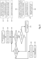
- the RF measurements of the target device is illustrated in Fig. 8 .
- the reception at the target device is represented by the following steps:
- the target device downloads 810 positioning information 815 from the base station 130 or from the location server 440.
- the positioning information 815, or receiver configuration 815 can comprise the number of devices, the reference signal, search window, time and frequency allocated resources.
- the target devices starts the measurement session 820.
- the target devices searches for a set of reference devices within the search windows 825.
- the target device searches 830 for reference signals using a search window.
- the target device searches for all the reference devices 835. If the target device does not find any reference signals of the reference devices it searches further until the last window or the maximum number of tries are reached. If the target device finds a reference signal, it tries to decode the PIB 860.
- the positioning information block is decoded 865. If the target device cannot decode the PIB of the reference signal the signal will be mapped to time/frequency resources 870, that means mapping measurement value to time/frequency information from the base station or from the location server 875. As the last window or the maximum tries are reached, the target device reports 880 the measurement set, e.g., decoded PIB, mapped time frequency resources, to the base station or to the location server. The target device reports the measurement values over LPP protocol or over NPP protocol or using higher layers 885. After reporting the target device finalizes 890 the session.
- the measurement set e.g., decoded PIB, mapped time frequency resources
- the target device In order to find reference signals of the reference devices, the target device using a search window.
- the usage of the search window is described in Fig. 9 and in Fig. 10 .
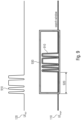
- Fig. 9 shows the reference signal 910 transmitted by the reference device 120.
- Fig. 9 further shows the reference signal 910 at the target device 110 in the middle of a search window 930.
- Fig. 9 further shows a time shift 920 between the reference signal 910 at the reference device 120 and the reference signal 910 at target device 110.
- a reference device 120 is transmitting a reference signal 910 and a target device 110 is receiving the reference signal 910 with a time shift 920.
- the base station 130 or the location server 440 assists the target device 110 to efficiently find the transmitted signal of the chosen reference device 310.
- the search window value and the uncertainty of window size are determined by the base station 130 or the location server 440 based on: the timing advance information, the maximum frequency offset between both devices, the maximum timing misalignment between both devices and the base station or the location server and the time needed between the transmission from the reference device and the reception at the target device.
- the base station or the location server informs the target device for example over LPP protocol with, for example, the signaling shown in Fig. 9 or 10 about the time of the first schedule transmission of a reference signal of a reference device.
- Fig. 10 shows reference signals 910 transmitted by the reference devices 120 and search windows 930 and 1020 at the target devices.
- the first reference device 120 is transmitting a periodical reference signal 1010.
- the second reference device transmits a single reference signal 910.
- the target device 110 use a search window 930 for finding or expecting the single reference signal 910, and the search windows 1020 for finding or expecting the periodical reference signal 1010.
- Fig. 10 illustrates a further use case for the search window 930.
- the first reference device 120 is transmitting the periodical signal 1010 and the second reference device 120 transmits a single reference signal 910.
- the base station 130 or the location server 440 assists the target device 110 to efficiently find the transmitted signals 910or 1010 of the reference devices 120 by not only providing information about the timing of the search window 930, but providing information about the periodicity of the first reference signal and the timing information of the first reference signal relative to the second reference signal.
- the target device 110 uses for example, the period information, frame ID and the pattern to track the next bursts of reference signals as shown with the red search windows 1020 in Fig. 10 . After successful detection and with the help of the information about the periodicity and the timing information relative to other reference signals, the target device can chose a shorter search window when predicting the next signal.
- Fig. 11 illustrates an appliance, comprising an antenna 1120, a target device 110 and a low power RF detector 1110. Both, the target device 110 and the low power RF detector 1110, are connected to the antenna 1120. the target device 110 and the low power RF detector 1110 are connected with each other. The target device is able to control 1150 the low power RF detector. The low power RF detector is capable of sending measured values 1130 to the target device 110.
- the RF measurement unit 1110 of the target device 110 can be either integrated in the receiving unit of the target device 110 or in the case of the target device 110 does not have a receiving unit, or the operation mode of the receiving unit does not support RF measurements, low power RF detector can be used.
- Fig. 11 illustrates an example where a target device 110 is connected to a low power RF detector1110 in order to perform RF measurements. The measurements of the low power RF detector 1110 is controlled 1150 by the target device 110, while the measurement results 1130 are sent back to the target device 110. Both the target device 110 and the low power RF detector 1110 needs to receive RF signals 1140, and are connected to an antenna 1120.
- the above described invention is used for enhancing the accuracy of the position calculation of the target device.
- a more accurate positioning of a mobile target device can be used in the following exemplary use cases:
- each method may be implemented as a program code.
- the program code being operative for performing one or more of the methods described above when the computer program runs on a computer.
- aspects have been described in the context of an apparatus, it is clear that these aspects also represent a description of the corresponding method, where a block or device corresponds to a method step or a feature of a method step. Analogously, aspects described in the context of a method step also represent a description of a corresponding block or item or feature of a corresponding apparatus.
- Some or all of the method steps may be executed by (or using) a hardware apparatus, like for example, a microprocessor, a programmable computer or an electronic circuit. In some embodiments, one or more of the most important method steps may be executed by such an apparatus.
- embodiments of the invention can be implemented in hardware or in software.
- the implementation can be performed using a digital storage medium, for example a floppy disk, a DVD, a Blu-Ray, a CD, a ROM, a PROM, an EPROM, an EEPROM or a FLASH memory, having electronically readable control signals stored thereon, which cooperate (or are capable of cooperating) with a programmable computer system such that the respective method is performed. Therefore, the digital storage medium may be computer readable.
- Some aspects comprise a data carrier having electronically readable control signals, which are capable of cooperating with a programmable computer system, such that one of the methods described herein is performed.
- aspects can be implemented as a computer program product with a program code, the program code being operative for performing one of the methods when the computer program product runs on a computer.
- the program code may for example be stored on a machine readable carrier.
- inventions comprise the computer program for performing one of the methods described herein, stored on a machine readable carrier.
- an embodiment of the inventive method is, therefore, a computer program having a program code for performing one of the methods described herein, when the computer program runs on a computer.
- a further aspect is, therefore, a data carrier (or a digital storage medium, or a computer-readable medium) comprising, recorded thereon, the computer program for performing one of the methods described herein.
- the data carrier, the digital storage medium or the recorded medium are typically tangible and/or non-transitionary.
- a further aspect is, therefore, a data stream or a sequence of signals representing the computer program for performing one of the methods described herein.
- the data stream or the sequence of signals may for example be configured to be transferred via a data communication connection, for example via the Internet.
- An aspect comprises a processing means, for example a computer, or a programmable logic device, configured to or adapted to perform one of the methods described herein.
- a further aspect comprises a computer having installed thereon the computer program for performing one of the methods described herein.
- a further aspect comprises an apparatus or a system configured to transfer (for example, electronically or optically) a computer program for performing one of the methods described herein to a receiver.
- the receiver may, for example, be a computer, a mobile device, a memory device or the like.
- the apparatus or system may, for example, comprise a file server for transferring the computer program to the receiver.
- a programmable logic device for example a field programmable gate array
- a field programmable gate array may cooperate with a microprocessor in order to perform one of the methods described herein.
- the methods are preferably performed by any hardware apparatus.
- the apparatus described herein may be implemented using a hardware apparatus, or using a computer, or using a combination of a hardware apparatus and a computer.
- the apparatus described herein, or any components of the apparatus described herein, may be implemented at least partially in hardware and/or in software.
- the methods described herein may be performed using a hardware apparatus, or using a computer, or using a combination of a hardware apparatus and a computer.
- eNB Enhanced GNSS Global Navigation Satellite System LS Location Server LTE Long Term Evolution SRS Sounding Reference Signal PRS Positioning Reference Signal PSS Primary Synchronization Signal SSS Secondary synchronization signal TP Transmission Point UE User Equipment RRC Radio Resource Control
Landscapes
- Engineering & Computer Science (AREA)
- Computer Networks & Wireless Communication (AREA)
- Signal Processing (AREA)
- Mobile Radio Communication Systems (AREA)
- Position Fixing By Use Of Radio Waves (AREA)
Claims (20)
- Ein Verfahren zum Bestimmen der Position einer Zielvorrichtung (110) innerhalb eines Kommunikationsnetzwerks (100), wobei das Verfahren folgende Schritte aufweist:Empfangen von Informationen (560, 670) von einer Basisstation (130) oder einem Standort-Server (440), innerhalb des Kommunikationsnetzwerks an der Zielvorrichtung;Erwarten eines von einer Referenzvorrichtung gesendeten Signals und Durchführen einer Hochfrequenz-HF-Messung durch Verwendung der Informationen, um einen Messwert zu erhalten, der von einem Abstand (510, 510a, 510b) zwischen der Zielvorrichtung und der Referenzvorrichtung abhängig ist, wobei die Zielvorrichtung die HF-Messung an dem erwarteten gesendeten Signal durchführt;wobei die Basisstation oder der Standort-Server die Referenzvorrichtung dahingehend ansteuert, das Signal (410, 540, 540a, 540b, 910, 1010) zu senden; undwobei das Verfahren ein Berechnen der Position der Zielvorrichtung auf Basis der Ergebnisse der HF-Messungen aufweist,dadurch gekennzeichnet, dass die empfangenen Informationen eine Sendezeit und Frequenzzuteilung der Referenzvorrichtung betreffen, gebildet durch eine Internetder-Dinge-, IOT,-Vorrichtung.
- Das Verfahren gemäß Anspruch 1, wobei das Verfahren eine grobe Schätzung der Zielvorrichtungsposition umfasst, wobei die grobe Schätzung von einer einzigen oder von mehreren Basisstationen oder von dem Standort-Server durchgeführt wird.
- Das Verfahren gemäß Anspruch 2, bei dem die Basisstation oder der Standort-Server die Referenzvorrichtung aus einer Ansammlung von Vorrichtungen innerhalb eines erfassbaren Bereichs um die Zielvorrichtung auswählt.
- Das Verfahren gemäß Anspruch 3, bei dem die Basisstation oder der Standort-Server Informationen über die Fähigkeiten und/oder die Konfigurationen der Zielvorrichtung von der Zielvorrichtung anfordert (520, 610) und die Zielvorrichtung der Basisstation oder dem Standort-Server als Antwort auf die Anforderung die Informationen über die Fähigkeiten und die Konfigurationen der Zielvorrichtung bereitstellt (520, 620).
- Das Verfahren gemäß Anspruch 4, bei dem die Basisstation oder der Standort-Server Informationen über die Fähigkeiten und/oder die Konfigurationen der Referenzvorrichtung von der Referenzvorrichtung anfordert (520, 630) und die Referenzvorrichtung der Basisstation oder dem Standort-Server als Antwort auf die Anforderung die Informationen über die Fähigkeiten und die Konfigurationen der Referenzvorrichtung bereitstellt (520, 640).
- Das Verfahren gemäß Anspruch 5, bei dem die Basisstation oder der Standort-Server von der Referenzvorrichtung oder von dem Standort-Server oder von der Basisstation über eine geplante Sendung informiert wird.
- Das Verfahren gemäß Anspruch 6, bei dem die Basisstation oder der Standort-Server Informationen über die geplante Sendung und/oder eine Sendezeit und/oder eine Frequenz der ausgewählten Referenzvorrichtung an die Zielvorrichtung sendet.
- Das Verfahren gemäß Anspruch 7, bei dem die Basisstation oder der Standort-Server ein Suchfenster (930, 1020) zum Finden des gesendeten Signals der Referenzvorrichtung angibt, um die HF-Messung durchzuführen.
- Das Verfahren gemäß Anspruch 8, bei dem die Zielvorrichtung die HF-Messung an dem gesendeten Signal der Referenzvorrichtung durchführt, wenn die Referenzvorrichtung dahingehend angesteuert wird, oder basierend auf den Informationen über die Sendezeit und Frequenz der Referenzvorrichtung.
- Das Verfahren gemäß Anspruch 9, bei dem die HF-Messung eine Messung einer Anzeige der empfangenen Signalstärke, RSSI, und/oder eines Signal-Rausch-Verhältnisses, SNR bzw. SNIR, und/oder einer Leistung des empfangenen Referenzsignals, RSRP, und/oder einer Qualität des empfangenen Referenzsignals, RSRQ, umfasst.
- Das Verfahren gemäß Anspruch 10, bei dem die Basisstation oder der Standort-Server Messergebnisse der HF-Messung von der Zielvorrichtung anfordert (570, 680) und die Zielvorrichtung der Basisstation oder dem Standort-Server als Antwort auf die Anforderung Messergebnisse der HF-Messung bereitstellt (450, 570, 690, 880); oder die Zielvorrichtung der Basisstation oder dem Standort-Server Messergebnisse der HF-Messung meldet (450, 570, 690, 880).
- Das Verfahren gemäß Anspruch 11, wobei das Verfahren ein Berechnen der Position der Zielvorrichtung auf Basis der gemeldeten Ergebnisse der HF-Messungen an dem Standort-Server (440) aufweist.
- Das Verfahren gemäß Anspruch 12, bei dem die Basisstation oder der Standort-Server eine oder mehrere Referenzvorrichtung zeitlich zuteilt und/oder die Zuteilung derselben aufhebt.
- Das Verfahren gemäß einem der Ansprüche 1 bis 13, das ferner ein Ansteuern der Referenzvorrichtung durch Verwendung einer Anforderung von Sendevorgängen aufweist.
- Das Verfahren gemäß einem der Ansprüche 1 bis 14, das folgende Schritte aufweist:Auswählen einer Referenzvorrichtung, wobei das Auswählen von einem Selektor einer Basisstation oder eines Standort-Servers durchgeführt wird;Identifizieren, ob die Referenzvorrichtung verfügbar ist und/oder fähig ist, die Zielvorrichtung zu unterstützen, wobei das Identifizieren von dem Standort-Server durchgeführt wird;Konfigurieren von Eigenschaften und/oder Perioden- und/oder Leistungseigenschaften der Referenzvorrichtung, wobei das Konfigurieren von der Basisstation oder von dem Standort-Server durchgeführt wird; undSenden von Informationen über die Referenzvorrichtung an eine Zielvorrichtung, sodass die Zielvorrichtung eine HF-Messung durch Verwendung der Informationen durchführen kann, um einen Messwert zu erhalten, der von einem Abstand zwischen der Zielvorrichtung und der Referenzvorrichtung abhängig ist, wobei das Senden von einem Sender der Basisstation oder des Standort-Servers durchgeführt wird.
- Eine Referenzvorrichtung,wobei dieselbe in einem Funkressourcensteuerungsverbindungsmodus ist, und/ oderwobei dieselbe dazu konfiguriert ist, dass auf Anforderung durch eine Basisstation oder durch einen Standort-Server mit einem Weck-Signal oder durch einen erweiterten, diskontinuierlichen Empfangsmechanismus zum Senden eines Signals ausgelöst zu werden, um die Fähigkeit einer Zielvorrichtung zu verbessern, das Signal von der Referenzvorrichtung zur Positionsbestimmung der Zielvorrichtung zu empfangen,wobei das gesendete Signaldazu konfiguriert ist, von der Basisstation oder von dem Standort-Server ausgelöst zu werden, oderdazu konfiguriert ist, eine zeitlich geplante Sendung der Referenzvorrichtung zu sein,dadurch gekennzeichnet, dass die Referenzvorrichtung durch eine IOT-Vorrichtung gebildet ist und Informationen in dem gesendeten Signal eine Sendezeit und Frequenzzuteilung der Referenzvorrichtung betreffen.
- Die Referenzvorrichtung gemäß Anspruch 16, die einen Sensor zum Bestimmen der Position einer beweglichen IOT-Referenzvorrichtung oder einer stationären IOT-Vorrichtung mit einer bekannten Position aufweist, wobei die Position der IOT-Referenzvorrichtung von dem Standort-Server bestimmt wird,
oder die einen Sensor zum Bestimmen der Position der beweglichen IOT-Referenzvorrichtung aufweist, wobei Sensorinformationen des Sensors an die Basisstation oder den Standort-Server gesendet werden. - Die Referenzvorrichtung gemäß Anspruch 16, die einen zweiten Sensor aufweist, der Geschwindigkeit und/oder Richtung misst, wobei die Referenzvorrichtung dazu konfiguriert ist, Sensorinformationen des zweiten Sensors an die Basisstation oder an den Standort-Server zu senden.
- Ein System (100), das eine Basisstation oder einen Standort-Server, eine Zielvorrichtung und eine oder mehrere Referenzvorrichtungen gemäß Ansprüchen 16 bis 18 aufweist, wobei das System dazu konfiguriert ist, ein Verfahren gemäß Ansprüchen 1 bis 15 durchzuführen.
- Ein Computerprogramm, das Befehle aufweist, die, wenn das Programm von entsprechenden Prozessoren von Zielvorrichtung und Basisstation oder Standort-Server ausgeführt wird, die Prozessoren dazu veranlassen, die Schritte des Verfahrens gemäß einem der Ansprüche 1 bis 15 auszuführen.
Priority Applications (1)
| Application Number | Priority Date | Filing Date | Title |
|---|---|---|---|
| EP23167876.4A EP4236508A1 (de) | 2018-12-14 | 2018-12-14 | Netzwerkunterstützte positionsmessungen |
Applications Claiming Priority (1)
| Application Number | Priority Date | Filing Date | Title |
|---|---|---|---|
| PCT/EP2018/085013 WO2020119925A1 (en) | 2018-12-14 | 2018-12-14 | Network assisted position measurements |
Related Child Applications (2)
| Application Number | Title | Priority Date | Filing Date |
|---|---|---|---|
| EP23167876.4A Division-Into EP4236508A1 (de) | 2018-12-14 | 2018-12-14 | Netzwerkunterstützte positionsmessungen |
| EP23167876.4A Division EP4236508A1 (de) | 2018-12-14 | 2018-12-14 | Netzwerkunterstützte positionsmessungen |
Publications (2)
| Publication Number | Publication Date |
|---|---|
| EP3895484A1 EP3895484A1 (de) | 2021-10-20 |
| EP3895484B1 true EP3895484B1 (de) | 2024-01-24 |
Family
ID=65009690
Family Applications (2)
| Application Number | Title | Priority Date | Filing Date |
|---|---|---|---|
| EP23167876.4A Pending EP4236508A1 (de) | 2018-12-14 | 2018-12-14 | Netzwerkunterstützte positionsmessungen |
| EP18830765.6A Active EP3895484B1 (de) | 2018-12-14 | 2018-12-14 | Netzwerkunterstützte positionsmessungen |
Family Applications Before (1)
| Application Number | Title | Priority Date | Filing Date |
|---|---|---|---|
| EP23167876.4A Pending EP4236508A1 (de) | 2018-12-14 | 2018-12-14 | Netzwerkunterstützte positionsmessungen |
Country Status (5)
| Country | Link |
|---|---|
| US (2) | US12621789B2 (de) |
| EP (2) | EP4236508A1 (de) |
| CN (2) | CN113330786B (de) |
| ES (1) | ES2970983T3 (de) |
| WO (1) | WO2020119925A1 (de) |
Families Citing this family (9)
| Publication number | Priority date | Publication date | Assignee | Title |
|---|---|---|---|---|
| US12041465B2 (en) | 2019-07-05 | 2024-07-16 | Telefonaktiebolaget Lm Ericsson (Publ) | Positioning signal search window configuration in a wireless communication system |
| GB201913574D0 (en) * | 2019-09-20 | 2019-11-06 | Nokia Technologies Oy | Position determination |
| CN117581603A (zh) * | 2021-07-08 | 2024-02-20 | 高通股份有限公司 | 用于ue定位的设备选择 |
| EP4367949A1 (de) | 2021-07-09 | 2024-05-15 | Fraunhofer-Gesellschaft zur Förderung der angewandten Forschung e.V. | Kommunikationssystem und benutzervorrichtung |
| CN116456268B (zh) * | 2022-01-07 | 2025-12-30 | 华为技术有限公司 | 定位方法和定位装置 |
| CN119318192A (zh) * | 2022-03-11 | 2025-01-14 | 诺基亚技术有限公司 | 定位参考单元选择 |
| CN119256568A (zh) * | 2022-05-31 | 2025-01-03 | Oppo广东移动通信有限公司 | 无线通信的方法及设备 |
| EP4345487B1 (de) | 2022-09-27 | 2026-03-11 | Nokia Solutions and Networks Oy | Auswahl einer positionierungsreferenzeinheit |
| GB2632340A (en) * | 2023-08-04 | 2025-02-05 | Nokia Technologies Oy | Method, apparatus and computer program for framework for PRU association for AIMLpositioning |
Family Cites Families (18)
| Publication number | Priority date | Publication date | Assignee | Title |
|---|---|---|---|---|
| US8730925B2 (en) | 2009-04-09 | 2014-05-20 | Motorola Mobility Llc | Method and apparatus for generating reference signals for accurate time-difference of arrival estimation |
| US9277523B2 (en) * | 2009-11-05 | 2016-03-01 | Qualcomm Incorporated | Method and apparatus for assisted positioning in a wireless communication system |
| US10267892B2 (en) * | 2010-10-04 | 2019-04-23 | Qualcomm Incorporated | Locating a device using a reference point to align location information |
| JP2016528776A (ja) * | 2013-06-26 | 2016-09-15 | エルジー エレクトロニクス インコーポレイティド | 大規模mimo方式のためのグルーピングベースの参照信号送信 |
| US10219257B2 (en) * | 2014-06-17 | 2019-02-26 | Lg Electronics Inc. | Method and device for transmitting uplink control information |
| WO2016032265A1 (ko) * | 2014-08-29 | 2016-03-03 | 엘지전자 주식회사 | 포지셔닝 지원을 위한 측정을 수행하는 방법 및 사용자기기와, 포지셔닝을 지원하는 방법 및 위치 서버와 포지셔닝을 지원하는 기지국 |
| US9491680B2 (en) * | 2014-10-28 | 2016-11-08 | Qualcomm Incorporated | Assistance data cell selection based on interference estimates in a wireless communications system |
| US9560627B2 (en) * | 2015-02-12 | 2017-01-31 | Qualcomm Incorporated | Assistance data for use in determining a position of a mobile device |
| US10560805B2 (en) | 2015-02-27 | 2020-02-11 | Telefonaktiebolaget Lm Ericcson (Publ) | Proximity based positioning in a wireless communications network |
| US10091758B2 (en) * | 2015-03-22 | 2018-10-02 | Lg Electronics Inc. | Method for reporting measurement result for determining position in wireless communication system, and device therefor |
| CN106664591B (zh) * | 2015-03-26 | 2020-06-30 | Lg 电子株式会社 | 在无线通信系统中报告用于确定位置的测量结果的方法及其设备 |
| WO2016163770A1 (ko) * | 2015-04-08 | 2016-10-13 | 엘지전자 주식회사 | 무선 통신 시스템에서 위치 결정을 위한 참조 신호 측정, 또는 위치 결정을 위한 방법 및 이를 위한 장치 |
| US10045325B2 (en) * | 2016-08-12 | 2018-08-07 | Innovative Technology Lab Co., Ltd. | Method and apparatus for transmitting/receiving positioning reference signal in wireless communication system |
| US10284343B2 (en) * | 2016-11-04 | 2019-05-07 | Qualcomm Incorporated | Frequency hopping for multicast service transmissions for narrowband devices |
| US10285156B2 (en) * | 2017-04-09 | 2019-05-07 | Qualcomm Incorporated | Dynamic measurement gap configuration for inter-frequency positioning measurements |
| CN108391311B (zh) * | 2018-01-09 | 2020-11-03 | 北京智联安科技有限公司 | NB-IoT设备定位方法及装置 |
| CN108506043A (zh) * | 2018-04-08 | 2018-09-07 | 安徽宏昌机电装备制造有限公司 | 一种基于nb-iot蜂窝物联网技术的井下智能互联设备监测系统及其人员定位方法 |
| US11057861B2 (en) * | 2018-10-31 | 2021-07-06 | Qualcomm Incorporated | Navigation and positioning system using radio beam support information |
-
2018
- 2018-12-14 CN CN201880100611.XA patent/CN113330786B/zh active Active
- 2018-12-14 WO PCT/EP2018/085013 patent/WO2020119925A1/en not_active Ceased
- 2018-12-14 CN CN202410394073.7A patent/CN118301736A/zh active Pending
- 2018-12-14 EP EP23167876.4A patent/EP4236508A1/de active Pending
- 2018-12-14 ES ES18830765T patent/ES2970983T3/es active Active
- 2018-12-14 EP EP18830765.6A patent/EP3895484B1/de active Active
-
2021
- 2021-06-14 US US17/346,469 patent/US12621789B2/en active Active
-
2025
- 2025-01-18 US US19/031,882 patent/US20250193834A1/en active Pending
Also Published As
| Publication number | Publication date |
|---|---|
| US20210345287A1 (en) | 2021-11-04 |
| EP3895484A1 (de) | 2021-10-20 |
| CN113330786A (zh) | 2021-08-31 |
| US20250193834A1 (en) | 2025-06-12 |
| CN113330786B (zh) | 2024-04-19 |
| WO2020119925A1 (en) | 2020-06-18 |
| US12621789B2 (en) | 2026-05-05 |
| CN118301736A (zh) | 2024-07-05 |
| EP4236508A1 (de) | 2023-08-30 |
| ES2970983T3 (es) | 2024-06-03 |
Similar Documents
| Publication | Publication Date | Title |
|---|---|---|
| US12621789B2 (en) | Network assisted position measurements | |
| US20220377701A1 (en) | Systems and methods to facilitate location determination by beamforming of a positioning reference signal | |
| KR102889573B1 (ko) | 포지셔닝 기준 신호 스태거링 구성을 위한 시스템들 및 방법들 | |
| KR102085001B1 (ko) | 포지셔닝 레퍼런스 시그널의 전송 | |
| CN111165033B (zh) | 无线通信网络中的观察到达时间差(Observed Time Difference of Arrival,OTDOA)定位 | |
| US8737998B2 (en) | Method and arrangement for processing of neighbor cell information | |
| US11316633B2 (en) | Bandwidth-dependent positioning reference signal (PRS) transmission for narrowband internet of things (NB-IoT) observed time difference of arrival (OTDOA) positioning | |
| US8942720B2 (en) | Positioning node, user equipment and methods therein | |
| EP2837230B1 (de) | Verwaltung ungewisser messgelegenheiten | |
| TWI537581B (zh) | 用於定位的增強量測間隙組態支援 | |
| JP5443598B2 (ja) | Otdoa測定の性能を改善するための干渉制御、sinr最適化、および信号強化 | |
| EP2606692B1 (de) | Positionierungsknoten, benutzergerät und verfahren dafür | |
| US20180231648A1 (en) | System and method to measure ue-to-ue distance based on d2d sidelink channel | |
| WO2020082017A1 (en) | Physical layer aspects of round-trip time and observed time difference of arrival based positioning | |
| US9696406B2 (en) | Apparatus and method for enhanced UL positioning support via wireless device | |
| CN104838674A (zh) | 使用小型小区众包通信网络中的信息 | |
| TW201415929A (zh) | 第二節點、定位節點及其中之方法 | |
| JP2012519870A (ja) | 無線通信システムにおける方法及び装置 | |
| CN109644422B (zh) | 无线电信网络内的位置参考信号的传输 | |
| HK40055028A (en) | Network assisted position measurements | |
| HK40113301A (zh) | 网络辅助位置测量 | |
| HK40055028B (zh) | 网络辅助位置测量 |
Legal Events
| Date | Code | Title | Description |
|---|---|---|---|
| STAA | Information on the status of an ep patent application or granted ep patent |
Free format text: STATUS: UNKNOWN |
|
| STAA | Information on the status of an ep patent application or granted ep patent |
Free format text: STATUS: THE INTERNATIONAL PUBLICATION HAS BEEN MADE |
|
| PUAI | Public reference made under article 153(3) epc to a published international application that has entered the european phase |
Free format text: ORIGINAL CODE: 0009012 |
|
| STAA | Information on the status of an ep patent application or granted ep patent |
Free format text: STATUS: REQUEST FOR EXAMINATION WAS MADE |
|
| 17P | Request for examination filed |
Effective date: 20210611 |
|
| AK | Designated contracting states |
Kind code of ref document: A1 Designated state(s): AL AT BE BG CH CY CZ DE DK EE ES FI FR GB GR HR HU IE IS IT LI LT LU LV MC MK MT NL NO PL PT RO RS SE SI SK SM TR |
|
| DAV | Request for validation of the european patent (deleted) | ||
| DAX | Request for extension of the european patent (deleted) | ||
| RAP3 | Party data changed (applicant data changed or rights of an application transferred) |
Owner name: FRAUNHOFER-GESELLSCHAFT ZUR FOERDERUNG DER ANGEWANDTEN FORSCHUNG E.V. |
|
| GRAP | Despatch of communication of intention to grant a patent |
Free format text: ORIGINAL CODE: EPIDOSNIGR1 |
|
| STAA | Information on the status of an ep patent application or granted ep patent |
Free format text: STATUS: GRANT OF PATENT IS INTENDED |
|
| INTG | Intention to grant announced |
Effective date: 20230105 |
|
| GRAJ | Information related to disapproval of communication of intention to grant by the applicant or resumption of examination proceedings by the epo deleted |
Free format text: ORIGINAL CODE: EPIDOSDIGR1 |
|
| STAA | Information on the status of an ep patent application or granted ep patent |
Free format text: STATUS: REQUEST FOR EXAMINATION WAS MADE |
|
| INTC | Intention to grant announced (deleted) | ||
| GRAP | Despatch of communication of intention to grant a patent |
Free format text: ORIGINAL CODE: EPIDOSNIGR1 |
|
| STAA | Information on the status of an ep patent application or granted ep patent |
Free format text: STATUS: GRANT OF PATENT IS INTENDED |
|
| INTG | Intention to grant announced |
Effective date: 20230705 |
|
| GRAS | Grant fee paid |
Free format text: ORIGINAL CODE: EPIDOSNIGR3 |
|
| GRAA | (expected) grant |
Free format text: ORIGINAL CODE: 0009210 |
|
| STAA | Information on the status of an ep patent application or granted ep patent |
Free format text: STATUS: THE PATENT HAS BEEN GRANTED |
|
| AK | Designated contracting states |
Kind code of ref document: B1 Designated state(s): AL AT BE BG CH CY CZ DE DK EE ES FI FR GB GR HR HU IE IS IT LI LT LU LV MC MK MT NL NO PL PT RO RS SE SI SK SM TR |
|
| REG | Reference to a national code |
Ref country code: GB Ref legal event code: FG4D |
|
| REG | Reference to a national code |
Ref country code: CH Ref legal event code: EP |
|
| REG | Reference to a national code |
Ref country code: DE Ref legal event code: R096 Ref document number: 602018064584 Country of ref document: DE |
|
| REG | Reference to a national code |
Ref country code: IE Ref legal event code: FG4D |
|
| P01 | Opt-out of the competence of the unified patent court (upc) registered |
Effective date: 20240209 |
|
| REG | Reference to a national code |
Ref country code: NL Ref legal event code: FP |
|
| REG | Reference to a national code |
Ref country code: LT Ref legal event code: MG9D |
|
| REG | Reference to a national code |
Ref country code: ES Ref legal event code: FG2A Ref document number: 2970983 Country of ref document: ES Kind code of ref document: T3 Effective date: 20240603 |
|
| PG25 | Lapsed in a contracting state [announced via postgrant information from national office to epo] |
Ref country code: IS Free format text: LAPSE BECAUSE OF FAILURE TO SUBMIT A TRANSLATION OF THE DESCRIPTION OR TO PAY THE FEE WITHIN THE PRESCRIBED TIME-LIMIT Effective date: 20240524 |
|
| PG25 | Lapsed in a contracting state [announced via postgrant information from national office to epo] |
Ref country code: LT Free format text: LAPSE BECAUSE OF FAILURE TO SUBMIT A TRANSLATION OF THE DESCRIPTION OR TO PAY THE FEE WITHIN THE PRESCRIBED TIME-LIMIT Effective date: 20240124 |
|
| PG25 | Lapsed in a contracting state [announced via postgrant information from national office to epo] |
Ref country code: GR Free format text: LAPSE BECAUSE OF FAILURE TO SUBMIT A TRANSLATION OF THE DESCRIPTION OR TO PAY THE FEE WITHIN THE PRESCRIBED TIME-LIMIT Effective date: 20240425 |
|
| REG | Reference to a national code |
Ref country code: AT Ref legal event code: MK05 Ref document number: 1653130 Country of ref document: AT Kind code of ref document: T Effective date: 20240124 |
|
| PG25 | Lapsed in a contracting state [announced via postgrant information from national office to epo] |
Ref country code: RS Free format text: LAPSE BECAUSE OF FAILURE TO SUBMIT A TRANSLATION OF THE DESCRIPTION OR TO PAY THE FEE WITHIN THE PRESCRIBED TIME-LIMIT Effective date: 20240424 Ref country code: HR Free format text: LAPSE BECAUSE OF FAILURE TO SUBMIT A TRANSLATION OF THE DESCRIPTION OR TO PAY THE FEE WITHIN THE PRESCRIBED TIME-LIMIT Effective date: 20240124 |
|
| PG25 | Lapsed in a contracting state [announced via postgrant information from national office to epo] |
Ref country code: AT Free format text: LAPSE BECAUSE OF FAILURE TO SUBMIT A TRANSLATION OF THE DESCRIPTION OR TO PAY THE FEE WITHIN THE PRESCRIBED TIME-LIMIT Effective date: 20240124 |
|
| PG25 | Lapsed in a contracting state [announced via postgrant information from national office to epo] |
Ref country code: RS Free format text: LAPSE BECAUSE OF FAILURE TO SUBMIT A TRANSLATION OF THE DESCRIPTION OR TO PAY THE FEE WITHIN THE PRESCRIBED TIME-LIMIT Effective date: 20240424 Ref country code: NO Free format text: LAPSE BECAUSE OF FAILURE TO SUBMIT A TRANSLATION OF THE DESCRIPTION OR TO PAY THE FEE WITHIN THE PRESCRIBED TIME-LIMIT Effective date: 20240424 Ref country code: LT Free format text: LAPSE BECAUSE OF FAILURE TO SUBMIT A TRANSLATION OF THE DESCRIPTION OR TO PAY THE FEE WITHIN THE PRESCRIBED TIME-LIMIT Effective date: 20240124 Ref country code: IS Free format text: LAPSE BECAUSE OF FAILURE TO SUBMIT A TRANSLATION OF THE DESCRIPTION OR TO PAY THE FEE WITHIN THE PRESCRIBED TIME-LIMIT Effective date: 20240524 Ref country code: HR Free format text: LAPSE BECAUSE OF FAILURE TO SUBMIT A TRANSLATION OF THE DESCRIPTION OR TO PAY THE FEE WITHIN THE PRESCRIBED TIME-LIMIT Effective date: 20240124 Ref country code: GR Free format text: LAPSE BECAUSE OF FAILURE TO SUBMIT A TRANSLATION OF THE DESCRIPTION OR TO PAY THE FEE WITHIN THE PRESCRIBED TIME-LIMIT Effective date: 20240425 Ref country code: FI Free format text: LAPSE BECAUSE OF FAILURE TO SUBMIT A TRANSLATION OF THE DESCRIPTION OR TO PAY THE FEE WITHIN THE PRESCRIBED TIME-LIMIT Effective date: 20240124 Ref country code: BG Free format text: LAPSE BECAUSE OF FAILURE TO SUBMIT A TRANSLATION OF THE DESCRIPTION OR TO PAY THE FEE WITHIN THE PRESCRIBED TIME-LIMIT Effective date: 20240124 Ref country code: AT Free format text: LAPSE BECAUSE OF FAILURE TO SUBMIT A TRANSLATION OF THE DESCRIPTION OR TO PAY THE FEE WITHIN THE PRESCRIBED TIME-LIMIT Effective date: 20240124 |
|
| PG25 | Lapsed in a contracting state [announced via postgrant information from national office to epo] |
Ref country code: PT Free format text: LAPSE BECAUSE OF FAILURE TO SUBMIT A TRANSLATION OF THE DESCRIPTION OR TO PAY THE FEE WITHIN THE PRESCRIBED TIME-LIMIT Effective date: 20240524 Ref country code: PL Free format text: LAPSE BECAUSE OF FAILURE TO SUBMIT A TRANSLATION OF THE DESCRIPTION OR TO PAY THE FEE WITHIN THE PRESCRIBED TIME-LIMIT Effective date: 20240124 |
|
| PG25 | Lapsed in a contracting state [announced via postgrant information from national office to epo] |
Ref country code: SE Free format text: LAPSE BECAUSE OF FAILURE TO SUBMIT A TRANSLATION OF THE DESCRIPTION OR TO PAY THE FEE WITHIN THE PRESCRIBED TIME-LIMIT Effective date: 20240124 Ref country code: PT Free format text: LAPSE BECAUSE OF FAILURE TO SUBMIT A TRANSLATION OF THE DESCRIPTION OR TO PAY THE FEE WITHIN THE PRESCRIBED TIME-LIMIT Effective date: 20240524 Ref country code: PL Free format text: LAPSE BECAUSE OF FAILURE TO SUBMIT A TRANSLATION OF THE DESCRIPTION OR TO PAY THE FEE WITHIN THE PRESCRIBED TIME-LIMIT Effective date: 20240124 Ref country code: LV Free format text: LAPSE BECAUSE OF FAILURE TO SUBMIT A TRANSLATION OF THE DESCRIPTION OR TO PAY THE FEE WITHIN THE PRESCRIBED TIME-LIMIT Effective date: 20240124 |
|
| PG25 | Lapsed in a contracting state [announced via postgrant information from national office to epo] |
Ref country code: DK Free format text: LAPSE BECAUSE OF FAILURE TO SUBMIT A TRANSLATION OF THE DESCRIPTION OR TO PAY THE FEE WITHIN THE PRESCRIBED TIME-LIMIT Effective date: 20240124 |
|
| PG25 | Lapsed in a contracting state [announced via postgrant information from national office to epo] |
Ref country code: SM Free format text: LAPSE BECAUSE OF FAILURE TO SUBMIT A TRANSLATION OF THE DESCRIPTION OR TO PAY THE FEE WITHIN THE PRESCRIBED TIME-LIMIT Effective date: 20240124 |
|
| PG25 | Lapsed in a contracting state [announced via postgrant information from national office to epo] |
Ref country code: CZ Free format text: LAPSE BECAUSE OF FAILURE TO SUBMIT A TRANSLATION OF THE DESCRIPTION OR TO PAY THE FEE WITHIN THE PRESCRIBED TIME-LIMIT Effective date: 20240124 Ref country code: EE Free format text: LAPSE BECAUSE OF FAILURE TO SUBMIT A TRANSLATION OF THE DESCRIPTION OR TO PAY THE FEE WITHIN THE PRESCRIBED TIME-LIMIT Effective date: 20240124 |
|
| REG | Reference to a national code |
Ref country code: DE Ref legal event code: R097 Ref document number: 602018064584 Country of ref document: DE |
|
| PG25 | Lapsed in a contracting state [announced via postgrant information from national office to epo] |
Ref country code: SK Free format text: LAPSE BECAUSE OF FAILURE TO SUBMIT A TRANSLATION OF THE DESCRIPTION OR TO PAY THE FEE WITHIN THE PRESCRIBED TIME-LIMIT Effective date: 20240124 |
|
| PG25 | Lapsed in a contracting state [announced via postgrant information from national office to epo] |
Ref country code: SM Free format text: LAPSE BECAUSE OF FAILURE TO SUBMIT A TRANSLATION OF THE DESCRIPTION OR TO PAY THE FEE WITHIN THE PRESCRIBED TIME-LIMIT Effective date: 20240124 Ref country code: SK Free format text: LAPSE BECAUSE OF FAILURE TO SUBMIT A TRANSLATION OF THE DESCRIPTION OR TO PAY THE FEE WITHIN THE PRESCRIBED TIME-LIMIT Effective date: 20240124 Ref country code: RO Free format text: LAPSE BECAUSE OF FAILURE TO SUBMIT A TRANSLATION OF THE DESCRIPTION OR TO PAY THE FEE WITHIN THE PRESCRIBED TIME-LIMIT Effective date: 20240124 Ref country code: EE Free format text: LAPSE BECAUSE OF FAILURE TO SUBMIT A TRANSLATION OF THE DESCRIPTION OR TO PAY THE FEE WITHIN THE PRESCRIBED TIME-LIMIT Effective date: 20240124 Ref country code: DK Free format text: LAPSE BECAUSE OF FAILURE TO SUBMIT A TRANSLATION OF THE DESCRIPTION OR TO PAY THE FEE WITHIN THE PRESCRIBED TIME-LIMIT Effective date: 20240124 Ref country code: CZ Free format text: LAPSE BECAUSE OF FAILURE TO SUBMIT A TRANSLATION OF THE DESCRIPTION OR TO PAY THE FEE WITHIN THE PRESCRIBED TIME-LIMIT Effective date: 20240124 |
|
| PLBE | No opposition filed within time limit |
Free format text: ORIGINAL CODE: 0009261 |
|
| STAA | Information on the status of an ep patent application or granted ep patent |
Free format text: STATUS: NO OPPOSITION FILED WITHIN TIME LIMIT |
|
| 26N | No opposition filed |
Effective date: 20241025 |
|
| PG25 | Lapsed in a contracting state [announced via postgrant information from national office to epo] |
Ref country code: SI Free format text: LAPSE BECAUSE OF FAILURE TO SUBMIT A TRANSLATION OF THE DESCRIPTION OR TO PAY THE FEE WITHIN THE PRESCRIBED TIME-LIMIT Effective date: 20240124 |
|
| PG25 | Lapsed in a contracting state [announced via postgrant information from national office to epo] |
Ref country code: MC Free format text: LAPSE BECAUSE OF FAILURE TO SUBMIT A TRANSLATION OF THE DESCRIPTION OR TO PAY THE FEE WITHIN THE PRESCRIBED TIME-LIMIT Effective date: 20240124 |
|
| REG | Reference to a national code |
Ref country code: CH Ref legal event code: PL |
|
| PG25 | Lapsed in a contracting state [announced via postgrant information from national office to epo] |
Ref country code: LU Free format text: LAPSE BECAUSE OF NON-PAYMENT OF DUE FEES Effective date: 20241214 |
|
| REG | Reference to a national code |
Ref country code: BE Ref legal event code: MM Effective date: 20241231 |
|
| PG25 | Lapsed in a contracting state [announced via postgrant information from national office to epo] |
Ref country code: BE Free format text: LAPSE BECAUSE OF NON-PAYMENT OF DUE FEES Effective date: 20241231 |
|
| PG25 | Lapsed in a contracting state [announced via postgrant information from national office to epo] |
Ref country code: CH Free format text: LAPSE BECAUSE OF NON-PAYMENT OF DUE FEES Effective date: 20241231 |
|
| PG25 | Lapsed in a contracting state [announced via postgrant information from national office to epo] |
Ref country code: IE Free format text: LAPSE BECAUSE OF NON-PAYMENT OF DUE FEES Effective date: 20241214 |
|
| PGFP | Annual fee paid to national office [announced via postgrant information from national office to epo] |
Ref country code: GB Payment date: 20251218 Year of fee payment: 8 |
|
| PGFP | Annual fee paid to national office [announced via postgrant information from national office to epo] |
Ref country code: FR Payment date: 20251218 Year of fee payment: 8 Ref country code: NL Payment date: 20251217 Year of fee payment: 8 |
|
| PGFP | Annual fee paid to national office [announced via postgrant information from national office to epo] |
Ref country code: ES Payment date: 20260119 Year of fee payment: 8 |
|
| PGFP | Annual fee paid to national office [announced via postgrant information from national office to epo] |
Ref country code: DE Payment date: 20251222 Year of fee payment: 8 |
|
| PGFP | Annual fee paid to national office [announced via postgrant information from national office to epo] |
Ref country code: IT Payment date: 20251231 Year of fee payment: 8 |
|
| PG25 | Lapsed in a contracting state [announced via postgrant information from national office to epo] |
Ref country code: CY Free format text: LAPSE BECAUSE OF FAILURE TO SUBMIT A TRANSLATION OF THE DESCRIPTION OR TO PAY THE FEE WITHIN THE PRESCRIBED TIME-LIMIT Effective date: 20240124 |