EP3894970B1 - Feldgeräteadapter zur drahtlosen datenübertragung - Google Patents
Feldgeräteadapter zur drahtlosen datenübertragung Download PDFInfo
- Publication number
- EP3894970B1 EP3894970B1 EP19801859.0A EP19801859A EP3894970B1 EP 3894970 B1 EP3894970 B1 EP 3894970B1 EP 19801859 A EP19801859 A EP 19801859A EP 3894970 B1 EP3894970 B1 EP 3894970B1
- Authority
- EP
- European Patent Office
- Prior art keywords
- adapter
- field device
- electronics
- switching element
- cable
- Prior art date
- Legal status (The legal status is an assumption and is not a legal conclusion. Google has not performed a legal analysis and makes no representation as to the accuracy of the status listed.)
- Active
Links
Images

Classifications
-
- H—ELECTRICITY
- H04—ELECTRIC COMMUNICATION TECHNIQUE
- H04L—TRANSMISSION OF DIGITAL INFORMATION, e.g. TELEGRAPHIC COMMUNICATION
- H04L69/00—Network arrangements, protocols or services independent of the application payload and not provided for in the other groups of this subclass
- H04L69/30—Definitions, standards or architectural aspects of layered protocol stacks
- H04L69/32—Architecture of open systems interconnection [OSI] 7-layer type protocol stacks, e.g. the interfaces between the data link level and the physical level
- H04L69/322—Intralayer communication protocols among peer entities or protocol data unit [PDU] definitions
- H04L69/323—Intralayer communication protocols among peer entities or protocol data unit [PDU] definitions in the physical layer [OSI layer 1]
-
- G—PHYSICS
- G05—CONTROLLING; REGULATING
- G05B—CONTROL OR REGULATING SYSTEMS IN GENERAL; FUNCTIONAL ELEMENTS OF SUCH SYSTEMS; MONITORING OR TESTING ARRANGEMENTS FOR SUCH SYSTEMS OR ELEMENTS
- G05B19/00—Program-control systems
- G05B19/02—Program-control systems electric
- G05B19/418—Total factory control, i.e. centrally controlling a plurality of machines, e.g. direct or distributed numerical control [DNC], flexible manufacturing systems [FMS], integrated manufacturing systems [IMS] or computer integrated manufacturing [CIM]
- G05B19/4185—Total factory control, i.e. centrally controlling a plurality of machines, e.g. direct or distributed numerical control [DNC], flexible manufacturing systems [FMS], integrated manufacturing systems [IMS] or computer integrated manufacturing [CIM] characterised by the network communication
- G05B19/4186—Total factory control, i.e. centrally controlling a plurality of machines, e.g. direct or distributed numerical control [DNC], flexible manufacturing systems [FMS], integrated manufacturing systems [IMS] or computer integrated manufacturing [CIM] characterised by the network communication by protocol, e.g. MAP, TOP
-
- H—ELECTRICITY
- H04—ELECTRIC COMMUNICATION TECHNIQUE
- H04B—TRANSMISSION
- H04B1/00—Details of transmission systems, not covered by a single one of groups H04B3/00 - H04B13/00; Details of transmission systems not characterised by the medium used for transmission
- H04B1/38—Transceivers, i.e. devices in which transmitter and receiver form a structural unit and in which at least one part is used for functions of transmitting and receiving
-
- G—PHYSICS
- G05—CONTROLLING; REGULATING
- G05B—CONTROL OR REGULATING SYSTEMS IN GENERAL; FUNCTIONAL ELEMENTS OF SUCH SYSTEMS; MONITORING OR TESTING ARRANGEMENTS FOR SUCH SYSTEMS OR ELEMENTS
- G05B2219/00—Program-control systems
- G05B2219/20—Pc systems
- G05B2219/25—Pc structure of the system
- G05B2219/25428—Field device
-
- Y—GENERAL TAGGING OF NEW TECHNOLOGICAL DEVELOPMENTS; GENERAL TAGGING OF CROSS-SECTIONAL TECHNOLOGIES SPANNING OVER SEVERAL SECTIONS OF THE IPC; TECHNICAL SUBJECTS COVERED BY FORMER USPC CROSS-REFERENCE ART COLLECTIONS [XRACs] AND DIGESTS
- Y02—TECHNOLOGIES OR APPLICATIONS FOR MITIGATION OR ADAPTATION AGAINST CLIMATE CHANGE
- Y02P—CLIMATE CHANGE MITIGATION TECHNOLOGIES IN THE PRODUCTION OR PROCESSING OF GOODS
- Y02P90/00—Enabling technologies with a potential contribution to greenhouse gas [GHG] emissions mitigation
- Y02P90/02—Total factory control, e.g. smart factories, flexible manufacturing systems [FMS] or integrated manufacturing systems [IMS]
Definitions
- the invention relates to a field device adapter for HART communication with a field device and an automation technology system.
- field devices are often used that are used to determine, optimize and/or influence process variables.
- Sensors such as level measuring devices, flow measuring devices, pressure and temperature measuring devices, conductivity measuring devices, etc. are used to record process variables, which record the corresponding process variables level, flow, pressure, temperature or conductivity.
- Actuators such as valves or pumps, are used to influence process variables and can be used to change the flow of a liquid in a pipe section or the fill level in a container.
- field devices are all devices that are used close to the process and that record process-relevant information, in particular one or more process variables (pressure, flow, temperature, etc.) or, in the case of actuators, provide one or more process variables.
- two-wire field devices are still common in a large number of existing automation systems, which are connected via a two-wire line to a higher-level unit, for example a PLC control unit.
- the two-wire field devices are designed in such a way that the measurement or control values are communicated, ie transmitted, as the main process variable via the two-wire line or the two-wire cable in the form of a 4-20 mA signal.
- the HART protocol has proven particularly useful for transmitting all other data, in which a frequency signal is superimposed on the analog current signal of 4-20 mA as a digital two-wire signal for data transmission.
- the HART communication resistor can either be integrated into a communication participant (field device, higher-level unit, operating unit) or can be incorporated into the two-wire cable as a quasi-independent unit.
- HART communication resistor is already installed in the two-wire line, for example to enable communication between a field device and a higher-level unit, in particular a PLC (programmable logic controller), there is no further HART communication resistor is switched to. This occurs in particular when HART communication to the field device is to take place from an operating unit.
- PLC programmable logic controller
- the DE 10 2008 036967 A1 discloses a universal interface for a wireless adapter that supports a communication protocol commonly used in automation technology.
- the WO 2016/165928 A1 discloses a method for automatically switching on or off a communication resistor of a HART device.
- the DE 10 2008 043199 A1 reveals a self-sufficient field device in automation technology.
- the invention is therefore based on the object of enabling HART communication to be as error-free as possible, in particular from an operating unit to a field device.
- an internal (HART) communication resistor of the field device adapter on or off via radio, so that an external HART communication resistor can be used if necessary.
- the internal (HART) communication resistance is bridged.
- the control can take place via a radio interface, such as Bluetooth or a modified variant, Bluetooth Low Energy. On the one hand, this can be done via a separate radio interface (separate configuration interface), or via an existing interface of the field device adapter for the wireless transmission of HART-based two-wire signals that are exchanged between a higher-level unit and a field device.
- the circuit for short-circuiting the communication resistor comprises at least one first switching element, preferably a transistor or an analog switch, which is connected in parallel to the communication resistor and which is switched on in the bridged state.
- the embodiment can provide that the circuit for short-circuiting the communication resistor further has a second and a third switching element, the second switching element being arranged in a third connecting line connecting the HART modem to the first connecting line and the third switching element is arranged in a fourth connecting line connecting the third connecting line to the second connecting line, and wherein the adapter electronics are set up to block the second switching element in the bridged state and the third and fourth switching elements depending on an installation position of an external HART communication resistor (36).
- the embodiment can provide that the adapter electronics further has a fifth connection element which can be contacted from outside the adapter housing and which is connected to the third connecting line via a fourth switching element, and wherein the adapter electronics is set up to connect the second and third switching elements in the bridged state to be switched off and the fourth switching element to be switched on, so that a bridging line can be connected to the first two-wire line via the fifth connection element.
- the embodiment can provide that the adapter electronics further has a fifth connection element which can be contacted from outside the adapter housing and which is connected to the third connecting line via a fourth switching element, and wherein the adapter electronics is set up to block the second switching element in the bridged state and that third switching element and preferably also the fourth switching element depending on an installation position of an external HART communication resistor.
- a further advantageous embodiment of the field device adapter according to the invention can provide that the adapter electronics are also set up to make the first switching element conductive, the second switching element and preferably also conductive in a switched-off state in which no HART communication initiated by the field device adapter is or should be to switch the third switching element to block.
- a further advantageous embodiment of the field device adapter according to the invention can provide that the adapter electronics comprise a second radio module (as a separate configuration interface) with an antenna for receiving the second radio signal, the supply circuit supplying the second radio module with energy through the supply voltage and the second radio module being set up for this purpose is to control the circuit for short-circuiting the communication resistor based on the second radio signal, and wherein the second radio module is set up to transmit the second radio signal according to a radio-based point-to-point connection, preferably a Bluetooth, a Bluetooth Low Energy, an NFC - or an RFID connection.
- a radio-based point-to-point connection preferably a Bluetooth, a Bluetooth Low Energy, an NFC - or an RFID connection.
- An advantageous embodiment of the system according to the invention can provide that the system further comprises a HART communication resistor arranged in a plus wire of the second two-wire line and a bridging line, the bridging line connecting the fifth connection element with the plus wire of the second two-wire line in the area between the supply circuit and connects the higher-level unit.
- An alternative embodiment of the system according to the invention can provide that the system further comprises a HART communication resistor arranged in a negative wire of the second two-wire line.
- Figure 1 shows schematically a two-wire field device, which includes a metallic housing 2 in which field device electronics 4 is arranged.
- the field device electronics 4 is designed in such a way that it has connection terminals 13, via which a first two-wire line 12a with a plus wire 12aa and a minus wire 12ab is electrically connected.
- the field device electronics 4 and thus the field device 1 are connected to an in Fig. 1
- a higher-level unit is connected in order to communicate data via wire with the higher-level unit.
- the measurement or control values are communicated as the main process variable via the first two-wire line 12a in an analogue manner in the form of a 4-20 mA current signal and all other data are transmitted in the form of a digital two-wire signal in accordance with the HART standard.
- the metallic housing 2 has a housing opening 3.
- a cable gland 5 is inserted into the housing opening 3, so that the first two-wire line 12a can be inserted into the housing 2 through the cable gland 5.
- the cable gland 5 is preferably in the form of a PG cable gland, ie a cable gland with a steel armored pipe thread, in accordance with the DIN EN 62444 standard published in May 2014 educated.
- the cable gland 5 can be designed, for example, as an M20, ie, a PG cable gland with an outer diameter of 20 mm.
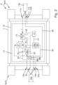
- Fig. 2 shows a schematic representation of a field device adapter 6 according to the invention for wireless data transmission.
- the field device adapter 6 includes an adapter housing 7 with an adapter chamber 10 and can, for example, have a substantially cylindrical shape.
- contacting means are provided on the end faces of the adapter housing 8, 9.
- a first and a second connection element 16a, 16b as well as a ground connection element 24a for connecting the first two-wire line 12a are provided.
- a third and a fourth connection element 11a, 11b and a ground connection 24b are provided for connecting the second two-wire line 12b.
- a fifth connection element 33 can be provided, which is guided to the outside, for example to the first or second end face 8, 9 of the adapter housing 7, for connecting a bridging line.
- the adapter housing 7 also has a cable gland 5a and 5b on the end faces 8, 9, through which the two-wire lines 12a, 12b are inserted.
- the fifth connection element 33 can also be accessible through one of the two cable glands.
- the cable glands 5 are preferably designed in the form of a PG cable gland, i.e. a cable gland with a steel armored pipe thread, in accordance with the DIN EN 62444 standard published in May 2014.
- the cable glands 5a, 5b can be designed, for example, as an M20, i.e. PG cable gland with an outer diameter of 20 mm.
- the field device adapter 6 has adapter electronics 14 arranged within the adapter chamber 10, which connects the first connection element 16a to the third connection element 11a via a first electrical connection line 25 and the second connection element 16b to the fourth connection element 11b via a second electrical connection line 26.
- a loop current I is conducted from the second two-wire line 12b to the first two-wire line 12a via the first electrical connecting line 25.
- the field device adapter 6 has a preferably unregulated supply circuit 15, ie a supply circuit which provides a defined supply voltage independently of the loop current and/or without a feedback circuit.
- the supply circuit 15 can, as in Fig. 2 shown, can be formed as part of the adapter electronics 14 or separately from the adapter electronics 14.
- the supply circuit 15 comprises at least one diode, which is introduced into the first electrical connecting line 25 and via which a supply voltage is provided by a voltage tap.
- a Z diode or Zener diode can be arranged in the first electrical connecting line 25 in such a way that an anode A is in the direction of the first connection element 16a and a cathode K is in the direction of the third connection element 11a, so that the Z diode is arranged in the reverse direction to the loop current I flowing through the first electrical connecting line 25 and the voltage is tapped between the anode A and the cathode K.
- the supply circuit 15 can also include several individual diodes, each of which is arranged in the flow direction of the loop current I flowing through the first electrical connecting line 25, with the voltage being tapped via the anode of the first diode and the cathode of the last diode.
- the adapter electronics 14 is connected at the first end 8 with the two connection elements 16a and 16b to the first two-wire line 12a and at the second end 9 with the two connection elements 11a and 11b to the second two-wire line 12b. Furthermore, the adapter electronics can be connected to a ground line of the first and second two-wire line via a first and second ground connection 24a and 24b.
- the adapter electronics 14 is further set up to forward in both directions a two-wire signal modulated onto the loop current, which is designed according to the HART standard and which is communicated between a field device connected via the first two-wire line and a higher-level unit connected via the second two-wire line. Furthermore, the adapter electronics 14 is set up to tap the modulated two-wire signals via a tap point 23 introduced into the first electrical connecting line 25 between the first connection element 16a and the supply circuit 15, to translate them into radio signals and to send them out by radio. For this purpose, the adapter electronics 14 has a first radio module 19a with an antenna.
- the first radio module 19a serves both to send two-wire signals that have already been modulated onto the loop current and, conversely, to wirelessly receive radio signals that represent two-wire signals and convert them into a corresponding two-wire signal so that it can be modulated onto the loop current.
- the field device adapter can be used to communicate with the field device using HART communication.
- the first radio module 19a is also supplied with energy by the supply circuit 15.
- the first radio module 19a is designed in such a way that, in particular, radio signals can be transmitted according to a Bluetooth protocol or a variant thereof, a 6LoWPAN protocol, a WirelessHART protocol, and/or a 6TiSCH protocol.
- the adapter electronics 14 further comprises a HART modem 17 for converting the modulated two-wire signals into signals suitable for transmission by means of the first radio module 19a and vice versa, which is connected for communication with the radio unit 19, for example by means of a serial interface 21, for example UART.
- the HART modem 17 is also supplied with energy by the supply circuit 15.
- a communication resistor 18 is also provided in the first electrical connecting line 25.
- a voltage modulation corresponding to the two-wire signal to be transmitted is implemented via the communication resistor 18.
- the communication resistor 18 is arranged between the supply circuit 15 and the tap point 23 in the first electrical connecting line 25.
- the HART modem 17 is set up as a secondary master.
- a field device 1 can be parameterized wirelessly via the field device adapter by converting the radio signals received wirelessly by the first radio module 19a using the HART modem 17 and modulating them onto the loop current via the tapping point 23.
- the adapter electronics further comprises a circuit for bridging the communication resistance in the event that an external HART communication resistance is already installed in the two-wire line.
- the circuit for bridging the communication resistor 18 comprises a first switching element 27, for example a transistor or an analog switch, which is connected in parallel to the communication resistor of the field device adapter 6, so that the communication resistor 18 can be short-circuited in a bridged state via the first switching element 27.
- the first switching element 27 can be switched to a non-bridged state so that the communication resistor 18 is not short-circuited and can be used for HART communication.
- the circuit for short-circuiting the communication resistor can also have a second and a third switching element 28a, 28b.
- the tap point required for HART communication can be changed or adjusted accordingly via the second and third switching elements 28a, 28b.
- the second switching element 28a is arranged in a third connecting line 34 connecting the HART modem 17 to the first connecting line 25 and the third switching element 28b is arranged in a fourth connecting line 35 connecting the third connecting line 34 to the second connecting line 26.
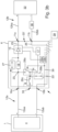
- Fig. 3b shows an example of such a configuration.
- the external HART communication resistor 36 that has already been installed actually serves to implement HART communication between the field device 1 and a higher-level unit 32.
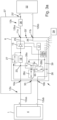
- Fig. 3a shows another configuration according to which the HART communication resistor is arranged in a plus wire 12aa of the first two-wire line 12a.
- a fifth connection element 33 that can be contacted from outside the adapter housing is provided in the adapter electronics.
- the fifth connection element 33 can, for example, be arranged in one of the two end faces and be connected to the third connecting line 34 via a fourth switching element 28c.
- the tap point 23 can be contacted with the line area between the already existing HART communication resistor 36 and the field device electronics 4 using an external bridging line 37.
- the contacting of the tap point with the line area is shown as an example with the reference number 23 '.
- the fourth switching element 28c is used in the event that the fifth connection element is not required, for example because the connection of the field device adapter is according to FIG Fig. 3b configuration shown is executed to deactivate it.
- the HART communication can be deactivated by the field device adapter via the first and second switching elements 27 and 28a, so that no two-wire signals can be modulated via the tap point.
- the first switching element 27 switched on and the second switching element 28a switched off. HART communication taking place between the field device and the higher-level unit remains unaffected.
Landscapes
- Engineering & Computer Science (AREA)
- Computer Networks & Wireless Communication (AREA)
- Signal Processing (AREA)
- Computer Security & Cryptography (AREA)
- General Engineering & Computer Science (AREA)
- Manufacturing & Machinery (AREA)
- Quality & Reliability (AREA)
- Physics & Mathematics (AREA)
- General Physics & Mathematics (AREA)
- Automation & Control Theory (AREA)
- Arrangements For Transmission Of Measured Signals (AREA)
- Programmable Controllers (AREA)
Description
- Die Erfindung bezieht sich auf einen Feldgeräteadapter zur HART Kommunikation mit einem Feldgerät und ein System der Automatisierungstechnik.
- In der Automatisierungstechnik, insbesondere in der Prozessautomatisierungstechnik, werden vielfach Feldgeräte eingesetzt, die zur Bestimmung, Optimierung und/oder Beeinflussung von Prozessgrößen dienen. Zur Erfassung von Prozessgrößen dienen Sensoren, wie beispielsweise Füllstandsmessgeräte, Durchflussmessgeräte, Druck- und Temperaturmessgeräte, Leitfähigkeitsmessgeräte, usw., welche die entsprechenden Prozessgrößen Füllstand, Durchfluss, Druck, Temperatur bzw. Leitfähigkeit erfassen. Zur Beeinflussung von Prozessgrößen dienen Aktoren, wie zum Beispiel Ventile oder Pumpen, über die der Durchfluss einer Flüssigkeit in einem Rohrleitungsabschnitt bzw. der Füllstand in einem Behälter geändert werden kann. Als Feldgeräte werden im Sinne dieser Anmeldung alle Geräte bezeichnet, die prozessnah eingesetzt werden und die prozessrelevanten Informationen, insbesondere eine oder mehrere Prozessgrößen (Druck, Durchfluss, Temperatur, etc.) erfassen oder im Falle von Aktoren eine oder mehrere Prozessgrößen stellen.
- Eine Vielzahl solcher Feldgeräte wird von der Firma Endress + Hauser hergestellt und vertrieben.
- Gegenwärtig sind in einer Vielzahl der bestehenden Automatisierungsanlagen noch Zweileiterfeldgeräte gängig, die über eine Zweidrahtleitung zu einer übergeordneten Einheit, bspw. eine Steuereinheit SPS, verbunden sind. Die Zweileiterfeldgeräte sind derartig ausgebildet, dass die Mess- bzw. Stellwerte als Haupt-Prozessgröße über die Zweidrahtleitung bzw. das Zweileiterkabel analog in Form eines 4-20 mA Signals kommuniziert, d.h. übertragen, werden. Zur Übertragung aller anderen Daten hat sich insbesondere das HART Protokoll bewährt, bei welchem dem analogen Stromsignal von 4-20 mA ein Frequenzsignal als digitales Zweileitersignal zur Datenübertragung überlagert wird. Gemäß dem HART Protokoll wird zwischen 1200 Hz und 2200 Hz zur Datenübertragung umgeschaltet, wobei die niedrigere Frequenz für eine logische "1" und die höhere Frequenz für eine logische "0" steht. Auf diese Weise bleibt das sich nur langsam veränderliche analoge Stromsignal von der Frequenzüberlagerung unberührt, sodass mittels HART analoge und digitale Kommunikation vereint wird.
- Um eine dem HART-Standard konforme Kommunikation auf der Zweidrahtleitung zu ermöglichen, ist ein HART Kommunikationswiderstand notwendig. Der HART Kommunikationswiderstand kann entweder in einen Kommunikationsteilnehmer (Feldgerät, übergeordnete Einheit, Bedieneinheit) integriert sein oder quasi als eigenständige Einheit in die Zweidrahtleitung eingebracht sein.
- Zu beachten gilt es allerdings, dass in dem Fall, dass bereits ein HART Kommunikationswiderstand in die Zweidrahtleitung eingebracht ist, bspw. um die Kommunikation zwischen einem Feldgerät und einer übergeordneten Einheit, insbesondere einer SPS (Speicherprogrammierbare Steuerung), zu ermöglichen, kein weiterer HART Kommunikationswiderstand zu geschaltet wird. Dies kommt insbesondere dann vor, wenn eine HART Kommunikation zu dem Feldgerät von einer Bedieneinheit aus erfolgen soll.
- Aus dem Stand der Technik sind die
DE 10 2008 036967 A1 , dieWO 2016/165928 A1 , dieDE 10 2008 043199 A1 sowie dieEP 2 984 530 A1 bekannt geworden. DieDE 10 2008 036967 A1 offenbart eine universelle Schnittstelle für einen Wireless Adapter, der ein in der Automatisierungstechnik gebräuchliches Kommunikationsprotokoll unterstützt. DieWO 2016/165928 A1 offenbart ein Verfahren zum automatischen Hinzu- oder Wegschalten eines Kommunikationswiderstandes eines HART-Gerätes. DieDE 10 2008 043199 A1 offenbart ein autarkes Feldgerät der Automatisierungstechnik. - Der Erfindung liegt somit die Aufgabe zugrunde eine möglichst fehlerfreie HART-Kommunikation, insbesondere von einer Bedieneinheit zu einem Feldgerät, zu ermöglichen.
- Die Aufgabe wird erfindungsgemäß gelöst durch den Feldgeräteadapter gemäß Patentanspruch 1 und das System gemäß Patentanspruch 9.
- Der erfindungsgemäße Feldgeräteadapter zur HART Kommunikation mit einem Feldgerät umfasst zumindest:
- ein Adaptergehäuse mit einem ersten Ende und einem zweiten Ende, wobei das erste Ende zumindest ein erstes Anschlusselement und ein zweites Anschlusselement zum elektrischen Anschließen einer ersten Zweidrahtleitung und das zweite Ende zumindest ein drittes Anschlusselement und ein viertes Anschlusselement zum elektrischen Anschließen einer zweiten Zweidrahtleitung aufweist, wobei das Adaptergehäuse ferner eine Adapterkammer zwischen dem ersten und dem zweiten Ende aufweist;
- eine in der Adapterkammer angeordnete Adapterelektronik, die das erste Anschlusselement mit dem dritten Anschlusselement durch eine erste elektrische Verbindungsleitung und das zweite Anschlusselement mit dem vierten Anschlusselement durch eine zweite elektrische Verbindungsleitung verbindet, wobei die Adapterelektronik ferner einen in die erste Verbindungsleitung eingebrachten Kommunikationswiderstand und eine, vorzugsweise ungeregelte bzw. nicht geregelte Versorgungschaltung zum Bereitstellen einer Versorgungsspannung aus einem in der ersten Verbindungsleitung fließenden Schleifenstrom umfasst, wobei die Adapterelektronik ferner ein als sekundärer Master eingerichtetes HART-Modem, welches über einen Abgriffspunkt mit der ersten Verbindungsleitung verbunden ist, und eine Schaltung zum Kurzschließen des Kommunikationswiderstandes aufweist, wobei die Adapterelektronik dazu eingerichtet ist, ein zweites Funksignal drahtlos zu empfangen und mittels des zweiten Funksignals die Schaltung zum Kurzschließen des Kommunikationswiderstandes derartig zu steuern, dass zumindest der Kommunikationswiderstand per Funk selektiv zu- oder abschaltbar ist, sodass in einem überbrückten Zustand ein durch die Adapterelektronik empfangenes erstes Funksignal in ein, vorzugsweise HART basiertes Zweileitersignal übersetzt und über den Abgriffspunkt auf den Schleifenstrom aufmoduliert werden kann.
- Erfindungsgemäß wird vorgeschlagen, einen internen (HART) Kommunikationswiderstand des Feldgeräteadapters per Funk ein- bzw. ausschalten, sodass gegebenenfalls ein externer HART Kommunikationswiderstand verwendet werden kann. Zum ein- bzw. ausschalten wird der interne (HART) Kommunikationswiderstand überbrückt. Die Steuerung kann über eine Funkschnittstelle, wie z.B. Bluetooth oder einer davon abgewandelten Variante Bluetooth Low Energy, erfolgen. Zum einen kann dies über eine separate Funkschnittstelle (separate Konfigurationsschnittstelle) erfolgen, oder über eine bereits vorhandene Schnittstelle des Feldgeräteadapters zur drahtlosen Übertragen von HART basierten Zweidrahtsignalen, die zwischen einer übergeordneten Einheit und einem Feldgerät ausgetauscht werden, erfolgen.
- Eine vorteilhafte Ausgestaltung des erfindungsgemäßen Feldgeräteadapters kann vorsehen, dass die Schaltung zum Kurzschließen des Kommunikationswiderstandes zumindest ein, vorzugsweise ein Transistor oder ein Analogschalter aufweisendes erstes Schaltelement umfasst, welches parallel zu dem Kommunikationswiderstand geschaltet ist und welches im überbrückten Zustand leitend geschaltet ist. Insbesondere kann die Ausgestaltung vorsehen, dass die Schaltung zum Kurzschließen des Kommunikationswiderstandes ferner ein zweites und ein drittes Schaltelement aufweist, wobei das zweite Schaltelement in einer das HART Modem mit der ersten Verbindungsleitung verbindenden dritten Verbindungsleitung angeordnet ist und das dritte Schaltelement in einer die dritte Verbindungsleitung mit der zweiten Verbindungsleitung verbindenden vierten Verbindungsleitung angeordnet ist, und wobei die Adapterelektronik dazu eingerichtet ist, in dem überbrückten Zustand in dem überbrückten Zustand das zweite Schaltelement sperrend und das dritte und vierte Schaltelement abhängig von einer Einbauposition eines externen HART Kommunikationswiderstands (36) zu schalten. Ergänzend kann die Ausgestaltung vorsehen, dass die Adapterelektronik ferner ein von außerhalb des Adaptergehäuses kontaktierbares fünftes Anschlusselement aufweist, welches über ein viertes Schaltelement mit der dritten Verbindungsleitung verbunden ist, und wobei die Adapterelektronik dazu eingerichtet ist, in dem überbrückten Zustand das zweite und dritte Schaltelement jeweils sperrend und das vierte Schaltelement leitend zu schalten, sodass über das fünfte Anschlusselement eine Überbrückungsleitung an die erste Zweidrahtleitung anschließbar ist. Alternativ kann die Ausgestaltung vorsehen, dass die Adapterelektronik ferner ein von außerhalb des Adaptergehäuses kontaktierbares fünftes Anschlusselement aufweist, welches über ein viertes Schaltelement mit der dritten Verbindungsleitung verbunden ist, und wobei die Adapterelektronik dazu eingerichtet ist, in dem überbrückten Zustand das zweite Schaltelement sperrend und das dritte Schaltelement und vorzugsweise auch das vierte Schaltelement abhängig von einer Einbauposition eines externen HART Kommunikationswiderstands zu schalten.
- Eine weitere vorteilhafte Ausgestaltung des erfindungsgemäßen Feldgeräteadapters kann vorsehen, dass die Adapterelektronik ferner dazu eingerichtet ist, in einem abgeschalteten Zustand, in dem keine durch den Feldgeräteadapter initiierte HART Kommunikation möglich ist bzw. sein soll, das erste Schaltelement leitend, das zweite Schaltelement und vorzugsweise auch das dritte Schaltelement sperrend zu schalten.
- Eine weitere vorteilhafte Ausgestaltung des erfindungsgemäßen Feldgeräteadapters kann vorsehen, dass die Adapterelektronik ein zweites Funkmodul (als eine separate Konfigurationsschnittstelle) mit einer Antenne zum Empfangen des zweiten Funksignals umfasst, wobei die Versorgungschaltung das zweite Funkmodul durch die Versorgungsspannung mit Energie versorgt und das zweite Funkmodul dazu eingerichtet ist, die Schaltung zum Kurzschließen des Kommunikationswiderstandes anhand des zweiten Funksignals zu steuern, und wobei das zweite Funkmodul dazu eingerichtet ist, das zweite Funksignal gemäß einer funkbasierten Punkt-zu-Punkt Verbindung, vorzugsweise eine Bluetooth-, eine Bluetooth Low Energy-, eine NFC- oder eine RFID-Verbindung, zu empfangen.
- Eine weitere vorteilhafte Ausgestaltung des erfindungsgemäßen Feldgeräteadapters kann vorsehen, dass die Adapterelektronik ein erstes Funkmodul mit einer Antenne zum Senden und/oder Empfangen des ersten Funksignals umfasst, wobei die Versorgungschaltung das erste Funkmodul durch die Versorgungsspannung mit Energie versorgt und das erste Funkmodul dazu eingerichtet ist, das Zweileitersignal in das erste Funksignal zu übersetzen und umgekehrt, wobei das erste Funkmodul ferner dazu eingerichtet ist, das erste Funksignal gemäß eines der folgenden Funkprotokolle bzw. Funktechnologien auszusenden bzw. zu empfangen:
- ein Bluetooth-Protokoll oder einer davon abgewandelten Variante,
- ein 6LoWPAN-Protokoll,
- ein WirelessHART-Protokoll,
- ein 6TiSCH-Protokoll, und/oder
- einem auf einer Mobilfunktechnologie aufbauenden Protokoll, vorzugsweise 2G, 3G, LTE oder 5G, besonders bevorzugt NB-loT.
- Die Erfindung betrifft weiterhin ein System der Automatisierungstechnik, aufweisend:
- zumindest ein Feldgeräteadapter nach einem oder mehreren der vorhergehenden Ansprüche;
- zumindest eine übergeordnete Einheit;
- zumindest ein Feldgerät der Automatisierungstechnik mit einer in einem Feldgerätegehäuse angeordneten Feldgeräteelektronik;
- eine erste Zweidrahtleitung, die die Adapterelektronik über das erste und zweite Anschlusselement elektrisch an die Feldgeräteelektronik anschließt;
- eine zweite Zweidrahtleitung, die die Adapterelektronik über das dritte und vierte Anschlusselement elektrisch an die übergeordnete Einheit anschließt;
- eine mobile Bedieneinheit die dazu eingerichtet ist, mit Hilfe des zweiten Funksignals die Schaltung zum Kurzschließen des Kommunikationswiderstandes derartig zu steuern, dass zumindest der Kommunikationswiderstand per Funk selektiv zu- oder abschaltbar ist.
- Eine vorteilhafte Ausgestaltung des erfindungsgemäßen Systems kann vorsehen, dass das System ferner einen in einer Plus-Ader der zweiten Zweidrahtleitung angeordneten HART Kommunikationswiderstand und eine Überbrückungsleitung umfasst, wobei die Überbrückungsleitung das fünfte Anschlusselement mit der Plus-Ader der zweiten Zweidrahtleitung im Bereich zwischen der Versorgungschaltung und der übergeordneten Einheit verbindet.
- Eine alternative Ausgestaltung des erfindungsgemäßen Systems kann vorsehen, dass das System ferner einen in einer Minus-Ader der zweiten Zweidrahtleitung angeordneten HART Kommunikationswiderstand umfasst.
- Die Erfindung wird anhand der nachfolgenden Zeichnungen näher erläutert. Es zeigt:
-
Fig. 1 : eine schematische Darstellung eines Zweileiterfeldgerätes, wie es gegenwärtig in einer Vielzahl der bestehenden Automatisierungsanlagen vorzufinden ist und mit welchem rein drahtgebunden über eine Zweidrahtleitung Daten kommuniziert werden können, -
Fig. 2 : eine schematische Darstellung eines erfindungsgemäßen Feldgeräteadapters zur drahtlosen Datenübertragung, -
Fig. 3a : eine erste schematisch dargestellte Konfiguration des erfindungsgemäßen Systems, und -
Fig. 3b : eine zweite schematische dargestellte Konfiguration des erfindungsgemäßen Systems. -
Figur 1 zeigt schematisch ein Zweileiterfeldgerät, welches ein metallisches Gehäuse 2 umfasst, indem eine Feldgeräteelektronik 4 angeordnet ist. Die Feldgeräteelektronik 4 ist derartig ausgebildet, dass diese Anschlussklemmen 13 aufweist, über die eine erste Zweidrahtleitung 12a mit einer Plus-Ader 12aa und einer Minus-Ader 12ab elektrisch angeschlossen ist. Über die erste Zweidrahtleitung wird die Feldgeräteelektronik 4 und somit das Feldgerät 1 an eine, inFig. 1 nicht gesondert dargestellte, übergeordnete Einheit angeschlossen, um mit der übergeordneten Einheit Daten drahtgebunden zu kommunizieren. Hierbei werden die Mess- bzw. Stellwerte als Haupt-Prozessgröße über die erste Zweidrahtleitung 12a analog in Form eines 4-20 mA Stromsignals kommuniziert und alle anderen Daten werden in Form eines digitalen Zweileitersignals gemäß dem HART Standard übertragen. - Um die von außerhalb des Gehäuses 2 kommende erste Zweidrahtleitung 12a mit der im Gehäuse 2 angeordneten Feldgeräteelektronik 4 elektrisch kontaktieren zu können, weist das metallische Gehäuse 2 eine Gehäuseöffnung 3 auf. In die Gehäuseöffnung 3 ist eine Kabelverschraubung 5 eingebracht, so dass die erste Zweidrahtleitung 12a durch die Kabelverschraubung 5 in das Gehäuse 2 einbringbar ist. Die Kabelverschraubung 5 ist vorzugsweise in Form einer PG-Kabelverschraubung, d.h. eine Kabelverschraubung mit Stahlpanzerrohrgewinde, gemäß der im Mai 2014 veröffentlichten Norm DIN EN 62444 ausgebildet. Die Kabelverschraubung 5 kann bspw. als M20, d.h. einen Außendurchmesser von 20 mm aufweisende, PG-Kabelverschraubung ausgebildet sein.
-
Fig. 2 zeigt eine schematische Darstellung eines erfindungsgemäßen Feldgeräteadapters 6 zur drahtlosen Datenübertragung. Der Feldgeräteadapter 6 umfasst ein Adaptergehäuse 7 mit einer Adapterkammer 10 und kann beispielsweise eine im Wesentlichen zylindrische Form aufweisen. Zum Anschließen jeweils einer ersten und zweiten Zweidrahtleitung 12a, 12b sind an den Stirnseiten des Adaptergehäuses 8, 9 jeweils Kontaktierungsmittel vorgesehen. An der ersten Stirnseite bzw. dem ersten Ende 8 sind ein erstes und ein zweites Anschlusselement 16a, 16b sowie ein Masseanschlusselement 24a zum Anschließen der ersten Zweidrahtleitung 12a vorgesehen. An der zweiten Stirnseite bzw. dem zweiten Ende 9 sind ein drittes und ein viertes Anschlusselement 11a, 11b sowie ein Masseanschluss 24b zum Anschließen der zweiten Zweidrahtleitung 12b vorgesehen. Ergänzend kann ein fünftes Anschlusselement 33 vorgesehen sein, welches zum Anschluss einer Überbrückungsleitung nach außen, bspw. an die erste oder zweite Stirnseite 8, 9 des Adaptergehäuses 7, geführt ist. - Das Adaptergehäuse 7 weist ferner in einer bevorzugten Ausgestaltung an den Stirnseiten 8, 9 jeweils eine Kabelverschraubung 5a und 5b auf, durch die die Zweidrahtleitungen 12a, 12b eingeführt werden. Das fünfte Anschlusselement 33 kann ebenfalls durch eine der beiden Kabelverschraubungen zugänglich sein. Die Kabelverschraubungen 5 sind vorzugsweise in Form einer PG-Kabelverschraubung, d.h. eine Kabelverschraubung mit Stahlpanzerrohrgewinde, gemäß der im Mai 2014 veröffentlichten Norm DIN EN 62444 ausgebildet. Die Kabelverschraubungen 5a, 5b können beispielsweise als M20, d.h. einen Außendurchmesser von 20 mm aufweisende, PG-Kabelverschraubung ausgebildet sein.
- Ferner weist der Feldgeräteadapter 6 eine innerhalb der Adapterkammer 10 angeordnete Adapterelektronik 14 auf, die das erste Anschlusselement 16a mit dem dritten Anschlusselement 11a über eine erste elektrische Verbindungsleitung 25 und das zweite Anschlusselement 16b mit dem vierten Anschlusselement 11b über eine zweite elektrische Verbindungsleitung 26 verbindet. Über die erste elektrische Verbindungsleitung 25 wird ein Schleifenstrom I von der zweiten Zweidrahtleitung 12b zu der ersten Zweidrahtleitung 12a geführt.
- Um eine Versorgungspannung zur Energieversorgung der Adapterelektronik 14 bereitzustellen, weist der Feldgeräteadapter 6 eine, vorzugsweise nicht geregelte Versorgungsschaltung 15 auf, d.h. eine Versorgungsschaltung die unabhängig von dem Schleifenstrom und/oder ohne eine Feedbackschaltung, eine definierte Versorgungsspannung bereitstellt. Die Versorgungsschaltung 15 kann, wie in
Fig. 2 dargestellt, als ein Teil der Adapterelektronik 14 oder separat von der Adapterelektronik 14 ausgebildet sein. Die Versorgungsschaltung 15 umfasst zumindest eine Diode, die in die erste elektrische Verbindungsleitung 25 eingebracht ist und über die durch einen Spannungsabgriff eine Versorgungsspannung bereitgestellt wird. Beispielsweise kann eine Z-Diode bzw. Zener-Diode derartig in der ersten elektrischen Verbindungsleitung 25 angeordnet sein, dass eine Anode A sich in Richtung des ersten Anschlusselementes 16a und eine Kathode K sich in Richtung des dritten Anschlusselementes 11a befindet, sodass die Z-Diode in Sperrrichtung zu dem durch die erste elektrische Verbindungsleitung 25 fließenden Schleifenstrom I angeordnet ist und der Spannungsabgriff zwischen der Anode A und der Kathode K erfolgt. - Alternativ kann die Versorgungsschaltung 15 auch mehrere einzelne Dioden, die jeweils in Flussrichtung zu dem durch die erste elektrische Verbindungsleitung 25 fließenden Schleifenstrom I angeordnet sind, umfassen, wobei der Spannungsabgriff über die Anode der ersten Diode und die Kathode der letzten Diode erfolgt.
- Die Adapterelektronik 14 ist an dem ersten Ende 8 mit den zwei Anschlusselementen 16a und 16b mit der ersten Zweidrahtleitung 12a und an dem zweiten Ende 9 mit den zwei Anschlusselementen 11a und 11b mit der zweiten Zweidrahtleitung 12b verbunden. Ferner kann die Adapterelektronik über einen ersten und zweiten Masseanschluss 24a und 24b mit einer Masseleitung der ersten bzw. zweiten Zweidrahtleitung verbunden sein.
- Die Adapterelektronik 14 ist ferner dazu eingerichtet, dass ein auf den Schleifenstrom aufmoduliertes Zweileitersignal, welches gemäß dem HART Standard ausgebildet ist und welches zwischen einem über die erste Zweidrahtleitung angeschlossenen Feldgerät und einer über die zweite Zweidrahtleitung angeschlossenen übergeordneten Einheit kommuniziert wird, in beide Richtungen weiterzuleiten. Ferner ist die Adapterelektronik 14 dazu eingerichtet, die aufmodulierten Zweileitersignale über einen zwischen dem ersten Anschlusselement 16a und der Versorgungsschaltung 15 in die erste elektrische Verbindungsleitung 25 eingebrachten Abgriffspunkt 23 abzugreifen, in Funksignale zu übersetzen und per Funk auszusenden. Hierzu weist die Adapterelektronik 14 ein erstes Funkmodul 19a mit einer Antenne auf. Das erste Funkmodul 19a dient sowohl dazu, dass bereits auf den Schleifenstrom aufmodulierte Zweileitersignal zu versenden als auch umgekehrt Zweileitersignale repräsentieren Funksignale drahtlos zu empfangen und in ein entsprechendes Zweileitersignal zu wandeln, sodass es auf den Schleifenstrom auf moduliert werden kann. Auf diese Weise kann über den Feldgeräteadapter mit dem Feldgerät mittels einer HART Kommunikation kommuniziert werden.
- Das erste Funkmodul 19a wird ebenfalls durch die Versorgungsschaltung 15 mit Energie versorgt. Das erste Funkmodul 19a ist derartig ausgebildet, dass insbesondere Funksignale gemäß einem Bluetooth-Protokoll oder einer davon abgewandelten Variante, einem 6LoWPAN-Protokoll, einem WirelessHART-Protokoll, und/oder einem 6TiSCH-Protokoll, übertragbar sind.
- Die Adapterelektronik 14 umfasst ferner zum Umsetzen der aufmodulierten Zweileitersignale in zur Übertragung mittels dem ersten Funkmodul 19a geeigneter Signale und umgekehrt ein HART-Modem 17, welches zur Kommunikation mit der Funkeinheit 19 bspw. mittels einer seriellen Schnittstelle 21, bspw. UART, verbunden ist. Das HART-Modem 17 wird ebenfalls durch die Versorgungsschaltung 15 mit Energie versorgt.
- Damit der Adapterelektronik 14 die aufmodulierten Zweileitersignale über den Abgriffspunkt 23 zugeführt oder auf den Schleifenstrom I aufmoduliert werden können, ist ferner ein Kommunikationswiderstand 18 in der ersten elektrischen Verbindungsleitung 25 vorgesehen. Über den Kommunikationswiderstand 18 wird eine gemäß dem zu übertragenden Zweileitersignal entsprechende Spannungsmodulation realisiert. Der Kommunikationswiderstand 18 ist hierbei zwischen der Versorgungsschaltung 15 und dem Abgriffspunkt 23 in der ersten elektrischen Verbindungsleitung 25 angeordnet.
- Damit die Adapterelektronik 14 digitale Zweileitersignale zu dem Feldgerät 1 kommunizieren kann, ist das HART Modem 17 als ein sekundärer Master eingerichtet. Auf diese Weise lässt sich bspw. ein Feldgerät 1 drahtlos per Funk über den Feldgeräteadapter parametrieren, indem die drahtlos durch das erste Funkmodul 19a empfangenen Funksignale mittels des HART-Modems 17 umgewandelt und über den Abgriffspunkt 23 auf den Schleifenstrom aufmoduliert werden.
- Erfindungsgemäß umfasst die Adapterelektronik ferner eine Schaltung zum Überbrücken des Kommunikationswiderstandes, für den Fall, dass bereits ein externer HART Kommunikationswiderstand in der Zweidrahtleitung eingebracht ist. Die Schaltung zum Überbrücken des Kommunikationswiderstandes 18 umfasst ein erstes Schaltelement 27, bspw. einen Transistor oder einen Analogschalter, der parallel zu dem Kommunikationswiderstand des Feldgeräteadapters 6 geschaltet ist, sodass sich über das erste Schaltelement 27 der Kommunikationswiderstand 18 in einem überbrückten Zustand kurzschließen lässt. Gleichfalls lässt sich das erste Schaltelement 27 in einen nicht überbrückten Zustand sperrend schalten, sodass der Kommunikationswiderstand 18 nicht kurzgeschlossen ist und dieser für die HART Kommunikation verwendet werden kann.
- Ergänzend kann die Schaltung zum Kurzschließen des Kommunikationswiderstandes ferner ein zweites und ein drittes Schaltelement 28a, 28b aufweisen. Über das zweite und dritte Schaltelement 28a, 28b lässt sich, in dem Fall, dass bereits ein externer HART Kommunikationswiderstand 36 in der Zweidrahtleitung vorhanden ist und der Kommunikationswiderstand 18 im überbrückten Zustand kurzgeschlossen ist, der zur HART Kommunikation notwendige Abgriffspunkt entsprechend verändern bzw. anpassen. Hierzu ist das zweite Schaltelement 28a in einer das HART Modem 17 mit der ersten Verbindungsleitung 25 verbindenden dritten Verbindungsleitung 34 angeordnet und das dritte Schaltelement 28b in einer die dritte Verbindungsleitung 34 mit der zweiten Verbindungsleitung 26 verbindenden vierten Verbindungsleitung 35 angeordnet. Auf diese Weise kann, wenn bereits ein externer HART Kommunikationswiderstand in einer Minus-Ader 12ab, 12ba der ersten oder zweiten Zweidrahtleitung 12a, 12b vorhanden ist, der Abgriffspunkt 23 zur zweiten Verbindungsleitung 26 geschaltet werden.
Fig. 3b zeigt exemplarisch eine solche Konfiguration. Der bereits eingebrachte externe HART Kommunikationswiderstand 36 dient eigentlich dazu, eine HART Kommunikation zwischen dem Feldgerät 1 und einer übergeordneten Einheit 32 zu realisieren. -
Fig. 3a zeigt eine andere Konfiguration gemäß derer der HART Kommunikationswiderstand in eine Plus-Ader 12aa der ersten Zweidrahtleitung 12a angeordnet ist. Um den zur HART Kommunikation notwendigen Abgriffspunkt in den Leitungsbereich zwischen dem bereits vorhandenen HART Kommunikationswiderstand 36 und der Feldgeräteelektronik 4 zu legen, ist in der Adapterelektronik ein von außerhalb des Adaptergehäuses kontaktierbares fünftes Anschlusselement 33 vorgesehen. Das fünfte Anschlusselement 33 kann bspw. in einer der beiden Stirnflächen angeordnet und über ein viertes Schaltelement 28c mit der dritten Verbindungsleitung 34 verbunden sein. Über das fünfte Anschlusselement 33 kann mittels einer externen Überbrückungsleitung 37 der Abgriffspunkt 23 mit dem Leitungsbereich zwischen dem bereits vorhandenen HART Kommunikationswiderstand 36 und der Feldgeräteelektronik 4 kontaktiert werden. InFig. 3a ist die Kontaktierung des Abgriffspunkts mit dem Leitungsbereich exemplarisch mit dem Bezugszeichen 23' dargestellt. Das vierte Schaltelement 28c dient dazu, in dem Fall, dass das fünfte Anschlusselement nicht benötigt wird, da bspw. der Anschluss des Feldgeräteadapters gemäß der inFig. 3b dargestellten Konfiguration ausgeführt wird, diesen zu deaktivieren. - Ergänzend oder alternativ kann über das erste und zweite Schaltelement 27 und 28a die HART Kommunikation durch den Feldgeräteadapter deaktiviert werden, sodass keine Zweileitersignale über den Abgriffspunkt aufmoduliert werden können. Hierzu wird das erste Schaltelement 27 leitend und das zweite Schaltelement 28a sperrend geschaltet. Eine zwischen dem Feldgerät und der übergeordneten Einheit stattfindende HART-Kommunikation bleibt davon unberührt.
- Um die einzelnen Schaltelemente zu steuern, ist eine elektrische Steuerleitung 39 vorgesehen, die die Schaltelemente mit einem zweiten Funkmodul 19b verbindet. Das zweite Funkmodul 19b ist dazu eingerichtet, ein zweites zum Steuern der Schaltung vorgesehenes Funksignal drahtlos zu empfangen und mittels des zweiten Funksignals die Schaltelemente entsprechend zu schalten. Die drahtlose Übertragung des zweiten Funksignals 19b erfolgt bevorzugt über eine funkbasierte Punkt-zu-Punkt Verbindung, bspw. eine Bluetooth-, eine Bluetooth Low Energy-, eine NFC- oder eine RFID-Verbindung. Das zweite Funkmodul 19b kann, wie in
Fig. 2 dargestellt, als separates Funkmodul ausgebildet sein. Alternativ können das erste und zweite Funkmodul 19a, 19b als ein einziges Modul ausgebildet sein. - 28c
- Viertes Schaltelement
- 31
- Automatisierungsanlage
- 32
- Übergeordnete Einheit
- 33
- Fünftes Anschlusselement
- 34
- Dritte Verbindungsleitung
- 35
- Vierte Verbindungsleitung
- 36
- Externer HART Kommunikationswiderstand
- 37
- Überbrückungsleitung
- 38
- Mobile Bedieneinheit
- 39
- Elektrische Steuerleitung
Claims (11)
- Feldgeräteadapter (6) zur HART Kommunikation mit einem Feldgerät (1), zumindest aufweisend:- ein Adaptergehäuse (7) mit einem ersten Ende (8) und einem zweiten Ende (9), wobei das erste Ende (8) zumindest ein erstes Anschlusselement (16a) und ein zweites Anschlusselement (16b) zum elektrischen Anschließen einer ersten Zweidrahtleitung (12a) und das zweite Ende (9) zumindest ein drittes Anschlusselement (11a) und ein viertes Anschlusselement (11b) zum elektrischen Anschließen einer zweiten Zweidrahtleitung (12b) aufweist, wobei das Adaptergehäuse (7) ferner eine Adapterkammer (10) zwischen dem ersten und dem zweiten Ende (8, 9) aufweist;
dadurch gekennzeichnet, dass- eine in der Adapterkammer (10) angeordnete Adapterelektronik (14) vorgesehen ist, die das erste Anschlusselement (16a) mit dem dritten Anschlusselement (11a) durch eine erste elektrische Verbindungsleitung (25) und das zweite Anschlusselement (16b) mit dem vierten Anschlusselement (11b) durch eine zweite elektrische Verbindungsleitung (26) verbindet, wobei die Adapterelektronik (14) ferner einen in die erste Verbindungsleitung (25) eingebrachten Kommunikationswiderstand (18) und eine, vorzugsweise ungeregelte bzw. nicht geregelte Versorgungschaltung (15) zum Bereitstellen einer Versorgungsspannung aus einem in der ersten Verbindungsleitung (25) fließenden Schleifenstrom (I) umfasst, wobei die Adapterelektronik (14) ferner ein als sekundärer Master eingerichtetes HART-Modem (17), welches über einen Abgriffspunkt (23) mit der ersten Verbindungsleitung (25) verbunden ist, und eine Schaltung zum Kurzschließen des Kommunikationswiderstandes (18) aufweist, wobei die Adapterelektronik dazu eingerichtet ist, ein zweites Funksignal drahtlos zu empfangen und mittels des zweiten Funksignals die Schaltung zum Kurzschließen des Kommunikationswiderstandes (18) derartig zu steuern, dass zumindest der Kommunikationswiderstand (18) per Funk selektiv zu- oder abschaltbar ist, sodass in einem überbrückten Zustand ein durch die Adapterelektronik (14) empfangenes erstes Funksignal in ein, vorzugsweise HART basiertes Zweileitersignal übersetzt und über den Abgriffspunkt (23) auf den Schleifenstrom (I) aufmoduliert werden kann. - Feldgeräteadapter nach Anspruch 1, wobei die Schaltung zum Kurzschließen des Kommunikationswiderstandes zumindest ein, vorzugsweise ein Transistor oder ein Analogschalter aufweisendes erstes Schaltelement (27) umfasst, welches parallel zu dem Kommunikationswiderstand (18) geschaltet ist und welches im überbrückten Zustand leitend geschaltet ist.
- Feldgeräteadapter nach dem vorhergehenden Anspruch, wobei die Schaltung zum Kurzschließen des Kommunikationswiderstandes ferner ein zweites und ein drittes Schaltelement (28a, 28b) aufweist, wobei das zweite Schaltelement (28a) in einer das HART Modem (17) mit der ersten Verbindungsleitung (25) verbindenden dritten Verbindungsleitung (34) angeordnet ist und das dritte Schaltelement (28b) in einer die dritte Verbindungsleitung (34) mit der zweiten Verbindungsleitung (26) verbindenden vierten Verbindungsleitung (35) angeordnet ist, und wobei die Adapterelektronik (14) dazu eingerichtet ist, in dem überbrückten Zustand das zweite Schaltelement (28a) sperrend und das dritte und vierte Schaltelement (28b, 28c) abhängig von einer Einbauposition eines externen HART Kommunikationswiderstands (36) zu schalten.
- Feldgeräteadapter nach dem vorhergehenden Anspruch, wobei die Adapterelektronik (14) ferner ein von außerhalb des Adaptergehäuses (7) kontaktierbares fünftes Anschlusselement (33) aufweist, welches über ein viertes Schaltelement (28c) mit der dritten Verbindungsleitung (34) verbunden ist, und wobei die Adapterelektronik (14) dazu eingerichtet ist, in dem überbrückten Zustand das zweite und dritte Schaltelement (28a, 28b) jeweils sperrend und das vierte Schaltelement (28c) leitend zu schalten, sodass über das fünfte Anschlusselement (33) eine Überbrückungsleitung (37) an die erste Zweidrahtleitung (12a) anschließbar ist.
- Feldgeräteadapter nach Anspruch 3, wobei die Adapterelektronik (14) ferner ein von außerhalb des Adaptergehäuses (7) kontaktierbares fünftes Anschlusselement (33) aufweist, welches über ein viertes Schaltelement (28c) mit der dritten Verbindungsleitung (34) verbunden ist, und wobei die Adapterelektronik (14) dazu eingerichtet ist, in dem überbrückten Zustand das zweite Schaltelement (28a) sperrend und das dritte Schaltelement (28b) und vorzugsweise auch das vierte Schaltelement (28c) abhängig von einer Einbauposition eines externen HART Kommunikationswiderstands (36) zu schalten.
- Feldgeräteadapter nach zumindest einem der Ansprüche 3 bis 5, wobei die Adapterelektronik (14) ferner dazu eingerichtet ist, in einem abgeschalteten Zustand, in dem keine durch den Feldgeräteadapter initiierte HART Kommunikation möglich ist bzw. sein soll, das erste Schaltelement (27) leitend, das zweite Schaltelement (28a) und vorzugsweise auch das dritte Schaltelement (28c) sperrend zu schalten.
- Feldgeräteadapter nach einem der vorhergehenden Ansprüche, wobei die Adapterelektronik (14) ein zweites Funkmodul (19b) mit einer Antenne zum Empfangen des zweiten Funksignals umfasst, wobei die Versorgungschaltung (15) das zweite Funkmodul (19b) durch die Versorgungsspannung mit Energie versorgt und das zweite Funkmodul (19b) dazu eingerichtet ist, die Schaltung zum Kurzschließen des Kommunikationswiderstandes anhand des zweiten Funksignals zu steuern, und wobei das zweite Funkmodul vorzugsweise dazu eingerichtet ist, das zweite Funksignal gemäß einer funkbasierten Punkt-zu-Punkt-Verbindung, vorzugsweise einer Bluetooth-, einer Bluetooth Low Energy-, NFC- oder RFID-Verbindung, zu empfangen.
- Feldgeräteadapter nach einem der vorhergehenden Ansprüche, wobei die Adapterelektronik (14) ein erstes Funkmodul (19a) mit einer Antenne zum Senden und/oder Empfangen des ersten Funksignals umfasst, wobei die Versorgungschaltung (15) das erste Funkmodul (19a) durch die Versorgungsspannung mit Energie versorgt und das erste Funkmodul (19a) dazu eingerichtet ist, das Zweileitersignal in das erste Funksignal zu übersetzen und umgekehrt, wobei das erste Funkmodul ferner dazu eingerichtet ist, das erste Funksignal gemäß eines der folgenden Funkprotokolle bzw. Funktechnologien auszusenden bzw. zu empfangen:- ein Bluetooth-Protokoll oder einer davon abgewandelten Variante,- ein 6LoWPAN-Protokoll,- ein WirelessHART-Protokoll,- ein 6TiSCH-Protokoll, und/oder- einem auf einer Mobilfunktechnologie aufbauenden Protokoll, vorzugsweise 2G, 3G, LTE oder 5G, besonders bevorzugt NB-loT.
- System der Automatisierungstechnik (1) aufweisend:- zumindest ein Feldgeräteadapter (6) nach einem oder mehreren der vorhergehenden Ansprüche;- zumindest eine übergeordnete Einheit (32);- zumindest ein Feldgerät der Automatisierungstechnik (1) mit einer in einem Feldgerätegehäuse (2) angeordneten Feldgeräteelektronik (4);- eine erste Zweidrahtleitung (12a), die die Adapterelektronik (14) über das erste und zweite Anschlusselement (16a, 16b) elektrisch an die Feldgeräteelektronik (4) anschließt;- eine zweite Zweidrahtleitung (12b), die die Adapterelektronik (14) über das dritte und vierte Anschlusselement (11a, 11b) elektrisch an die übergeordnete Einheit (32) anschließt;- eine mobile Bedieneinheit (39) die dazu eingerichtet ist, mit Hilfe des zweiten Funksignals die Schaltung zum Kurzschließen des Kommunikationswiderstandes derartig zu steuern, dass zumindest der Kommunikationswiderstand (18) per Funk selektiv zu- oder abschaltbar ist.
- System nach dem vorhergehenden Anspruch, wobei der zumindest eine Feldgeräteadapter (6) nach Anspruch 4 ausgebildet ist, und wobei das System ferner einen in einer Plus-Ader der zweiten Zweidrahtleitung (12ba) angeordneten HART Kommunikationswiderstand (36) und die Überbrückungsleitung (37) umfasst, wobei die Überbrückungsleitung (37) das fünfte Anschlusselement (33) mit der Plus-Ader der zweiten Zweidrahtleitung (12ba) im Bereich zwischen der Versorgungschaltung (15) und der übergeordneten Einheit (32) verbindet.
- System nach Anspruch 9, wobei der zumindest eine Feldgeräteadapter (6) nach Anspruch 5 ausgebildet ist, und wobei das System ferner einen in einer Minus-Ader der zweiten Zweidrahtleitung (12bb) angeordneten HART Kommunikationswiderstand (36) umfasst.
Applications Claiming Priority (2)
| Application Number | Priority Date | Filing Date | Title |
|---|---|---|---|
| DE102018131685.2A DE102018131685A1 (de) | 2018-12-11 | 2018-12-11 | Feldgeräteadapter zur drahtlosen Datenübertragung |
| PCT/EP2019/080818 WO2020120045A1 (de) | 2018-12-11 | 2019-11-11 | Feldgeräteadapter zur drahtlosen datenübertragung |
Publications (2)
| Publication Number | Publication Date |
|---|---|
| EP3894970A1 EP3894970A1 (de) | 2021-10-20 |
| EP3894970B1 true EP3894970B1 (de) | 2023-10-18 |
Family
ID=68536862
Family Applications (1)
| Application Number | Title | Priority Date | Filing Date |
|---|---|---|---|
| EP19801859.0A Active EP3894970B1 (de) | 2018-12-11 | 2019-11-11 | Feldgeräteadapter zur drahtlosen datenübertragung |
Country Status (5)
| Country | Link |
|---|---|
| US (1) | US11336758B2 (de) |
| EP (1) | EP3894970B1 (de) |
| CN (1) | CN113168164B (de) |
| DE (1) | DE102018131685A1 (de) |
| WO (1) | WO2020120045A1 (de) |
Families Citing this family (3)
| Publication number | Priority date | Publication date | Assignee | Title |
|---|---|---|---|---|
| DE102020124434A1 (de) * | 2020-09-18 | 2022-03-24 | Endress+Hauser SE+Co. KG | Feldgeräteadapter zur drahtlosen Datenübertragung |
| US11729272B2 (en) * | 2020-09-25 | 2023-08-15 | Texas Instruments Incorporated | Hart-enabled device with reduced communication lines and break extension protocol |
| CN114779706B (zh) * | 2022-05-11 | 2025-04-08 | 中控技术股份有限公司 | 一种自动切换回路的hart设备通讯器 |
Citations (2)
| Publication number | Priority date | Publication date | Assignee | Title |
|---|---|---|---|---|
| EP2340468B1 (de) * | 2008-10-27 | 2012-09-19 | Endress + Hauser Process Solutions AG | Autarkes feldgerät |
| EP2984530B1 (de) * | 2013-04-08 | 2018-09-12 | Endress+Hauser Wetzer GmbH+Co. KG | Messumformerspeisegerät mit abschaltbarer funkschnittstelle |
Family Cites Families (17)
| Publication number | Priority date | Publication date | Assignee | Title |
|---|---|---|---|---|
| DE10352286B4 (de) * | 2003-11-08 | 2007-10-11 | Insta Elektro Gmbh | Elektrisches/elektronisches Steuersystem |
| US8160535B2 (en) * | 2004-06-28 | 2012-04-17 | Rosemount Inc. | RF adapter for field device |
| DE102007045884A1 (de) * | 2007-09-25 | 2009-04-09 | Endress + Hauser Process Solutions Ag | Verfahren zum Betreiben eines Feldgerätes in einem leistungsangepassten Modus |
| DE102008036554A1 (de) * | 2008-08-06 | 2010-02-11 | Endress + Hauser Process Solutions Ag | Autarkes Feldgerät oder autarker Funkadapter für ein Feldgerät der Automatisierungstechnik |
| DE102008036967A1 (de) * | 2008-08-08 | 2010-02-11 | Endress + Hauser Process Solutions Ag | Universelle Schnittstelle für einen Wireless Adapter |
| EP2199881B1 (de) * | 2008-12-18 | 2013-04-24 | Endress + Hauser Process Solutions AG | Feldgerät der Automatisierungstechnik |
| DE102009047535B4 (de) * | 2009-12-04 | 2023-12-07 | Endress + Hauser Process Solutions Ag | Verfahren zum Ermitteln einer Anschlusskonfiguration eines Feldgerätes an einem Wireless Adapter |
| US10761524B2 (en) * | 2010-08-12 | 2020-09-01 | Rosemount Inc. | Wireless adapter with process diagnostics |
| US9310794B2 (en) * | 2011-10-27 | 2016-04-12 | Rosemount Inc. | Power supply for industrial process field device |
| DE102012102516A1 (de) * | 2012-03-23 | 2013-09-26 | Endress + Hauser Gmbh + Co. Kg | Verfahren zum Bedienen eines Feldgerätes |
| DE102013109096A1 (de) * | 2013-08-22 | 2015-02-26 | Endress + Hauser Flowtec Ag | Gegen Manipulation geschütztes elektronisches Gerät |
| US9544027B2 (en) * | 2014-02-19 | 2017-01-10 | Texas Instruments Incorporated | Loop powered transmitter with a single tap data isolation transformer and unipolar voltage converters |
| DE102014110385B4 (de) * | 2014-07-23 | 2018-01-11 | Endress+Hauser Conducta Gmbh+Co. Kg | Eigensicherer Funkdongle für ein Feldgerät |
| WO2016019982A1 (de) * | 2014-08-05 | 2016-02-11 | Vega Grieshaber Kg | Verbindevorrichtung und verfahren zum verbinden |
| DE102015105887A1 (de) * | 2015-04-17 | 2016-10-20 | Endress + Hauser Process Solutions Ag | Verfahren zum automatischen Hinzu- oder Wegschalten eines Kommunikationswiderstandes eines HART-Gerätes |
| EP3311503B1 (de) * | 2015-08-12 | 2019-07-03 | Festo AG & Co. KG | Feldgerät-koppeleinrichtung und system |
| DE102017114851A1 (de) * | 2017-07-04 | 2019-01-10 | Endress+Hauser SE+Co. KG | Feldgeräteadapter zur drahtlosen Datenübertragung |
-
2018
- 2018-12-11 DE DE102018131685.2A patent/DE102018131685A1/de not_active Withdrawn
-
2019
- 2019-11-11 CN CN201980080964.2A patent/CN113168164B/zh active Active
- 2019-11-11 EP EP19801859.0A patent/EP3894970B1/de active Active
- 2019-11-11 WO PCT/EP2019/080818 patent/WO2020120045A1/de not_active Ceased
- 2019-11-11 US US17/312,256 patent/US11336758B2/en active Active
Patent Citations (2)
| Publication number | Priority date | Publication date | Assignee | Title |
|---|---|---|---|---|
| EP2340468B1 (de) * | 2008-10-27 | 2012-09-19 | Endress + Hauser Process Solutions AG | Autarkes feldgerät |
| EP2984530B1 (de) * | 2013-04-08 | 2018-09-12 | Endress+Hauser Wetzer GmbH+Co. KG | Messumformerspeisegerät mit abschaltbarer funkschnittstelle |
Also Published As
| Publication number | Publication date |
|---|---|
| US20220038562A1 (en) | 2022-02-03 |
| DE102018131685A1 (de) | 2020-06-18 |
| CN113168164B (zh) | 2024-10-18 |
| US11336758B2 (en) | 2022-05-17 |
| EP3894970A1 (de) | 2021-10-20 |
| CN113168164A (zh) | 2021-07-23 |
| WO2020120045A1 (de) | 2020-06-18 |
Similar Documents
| Publication | Publication Date | Title |
|---|---|---|
| EP2984530B1 (de) | Messumformerspeisegerät mit abschaltbarer funkschnittstelle | |
| EP3649631B1 (de) | Feldgeräteadapter zur drahtlosen datenübertragung | |
| EP4097927B1 (de) | Spe-basierter geräteadapter zum anschliessen eines nicht ethernet-fähigen feldgerätes an ein ethernet-basiertes prozesssteuerungssystem | |
| EP4115246B1 (de) | Feldgeräteadapter zur drahtlosen datenübertragung | |
| DE102008053920A1 (de) | Verteilermodul bzw. damit gebildetes Messsystem | |
| DE19646219A1 (de) | Schaltung für die Kommunikation externer Geräte mit einer zentralen/dezentralen Datenverarbeitungsanlage über einen Bus | |
| WO2020120045A1 (de) | Feldgeräteadapter zur drahtlosen datenübertragung | |
| EP3526928A1 (de) | Verfahren zur datenübertragung zwischen einem feldgerät der automatisierungstechnik und einer kommunikationsbox | |
| WO2021121743A1 (de) | Vorrichtung zur drahtlosen übermittlung eines signals | |
| EP3465364A1 (de) | Funkadapter für ein feldgerät mit einer antenne für zwei kommunikationsstandards | |
| EP3983853B1 (de) | Feldgerät der automatisierungstechnik | |
| EP3821308B1 (de) | System zur erhebung von daten aus einer anlage der automatisierungstechnik | |
| WO2009074545A2 (de) | Vorrichtung zur übertragung von elektrischer energie und information | |
| EP3529672B1 (de) | Verfahren, kommunikationsmodul und system zur übermittlung von diagnosedaten eines feldgeräts in einer anlage der prozessautomatisierung | |
| EP3586201B1 (de) | Frontadapter zum verbinden mit einer steuerungseinrichtung und automatisierungssystem | |
| DE102017107535A1 (de) | Power over Ethernet-basiertes Feldgerät der Automatisierungstechnik | |
| EP3097751B1 (de) | Verbindungsadaptersystem der steuerungstechnik | |
| DE10131094B4 (de) | Eigensicheres Koppler-Modul zum Anschluss an ein Datennetzwerk | |
| EP1712968A2 (de) | Automatisierungssystem | |
| WO2019034336A1 (de) | Drahtlosadapter und system | |
| LU101865B1 (de) | Technik zum Verarbeiten und Austauschen von Signalen zwischen Feldgerät und Steuerung | |
| WO2020104544A1 (de) | Feldgeräteadapter zur drahtlosen datenübertragung | |
| WO2022058104A1 (de) | Feldgeräteadapter zur drahtlosen datenübertragung | |
| DE10032866A1 (de) | System, insbesondere Automatisierungssystem, mit software-implementierter Steuerung und Basisstation hierzu | |
| EP3153938B1 (de) | Messanordnung |
Legal Events
| Date | Code | Title | Description |
|---|---|---|---|
| STAA | Information on the status of an ep patent application or granted ep patent |
Free format text: STATUS: UNKNOWN |
|
| STAA | Information on the status of an ep patent application or granted ep patent |
Free format text: STATUS: THE INTERNATIONAL PUBLICATION HAS BEEN MADE |
|
| PUAI | Public reference made under article 153(3) epc to a published international application that has entered the european phase |
Free format text: ORIGINAL CODE: 0009012 |
|
| STAA | Information on the status of an ep patent application or granted ep patent |
Free format text: STATUS: REQUEST FOR EXAMINATION WAS MADE |
|
| 17P | Request for examination filed |
Effective date: 20210507 |
|
| AK | Designated contracting states |
Kind code of ref document: A1 Designated state(s): AL AT BE BG CH CY CZ DE DK EE ES FI FR GB GR HR HU IE IS IT LI LT LU LV MC MK MT NL NO PL PT RO RS SE SI SK SM TR |
|
| DAV | Request for validation of the european patent (deleted) | ||
| DAX | Request for extension of the european patent (deleted) | ||
| GRAP | Despatch of communication of intention to grant a patent |
Free format text: ORIGINAL CODE: EPIDOSNIGR1 |
|
| STAA | Information on the status of an ep patent application or granted ep patent |
Free format text: STATUS: GRANT OF PATENT IS INTENDED |
|
| INTG | Intention to grant announced |
Effective date: 20230526 |
|
| GRAS | Grant fee paid |
Free format text: ORIGINAL CODE: EPIDOSNIGR3 |
|
| GRAA | (expected) grant |
Free format text: ORIGINAL CODE: 0009210 |
|
| STAA | Information on the status of an ep patent application or granted ep patent |
Free format text: STATUS: THE PATENT HAS BEEN GRANTED |
|
| AK | Designated contracting states |
Kind code of ref document: B1 Designated state(s): AL AT BE BG CH CY CZ DE DK EE ES FI FR GB GR HR HU IE IS IT LI LT LU LV MC MK MT NL NO PL PT RO RS SE SI SK SM TR |
|
| REG | Reference to a national code |
Ref country code: GB Ref legal event code: FG4D Free format text: NOT ENGLISH |
|
| REG | Reference to a national code |
Ref country code: CH Ref legal event code: EP |
|
| REG | Reference to a national code |
Ref country code: IE Ref legal event code: FG4D Free format text: LANGUAGE OF EP DOCUMENT: GERMAN |
|
| REG | Reference to a national code |
Ref country code: DE Ref legal event code: R096 Ref document number: 502019009719 Country of ref document: DE |
|
| P01 | Opt-out of the competence of the unified patent court (upc) registered |
Effective date: 20231031 |
|
| REG | Reference to a national code |
Ref country code: LT Ref legal event code: MG9D |
|
| REG | Reference to a national code |
Ref country code: NL Ref legal event code: MP Effective date: 20231018 |
|
| PG25 | Lapsed in a contracting state [announced via postgrant information from national office to epo] |
Ref country code: NL Free format text: LAPSE BECAUSE OF FAILURE TO SUBMIT A TRANSLATION OF THE DESCRIPTION OR TO PAY THE FEE WITHIN THE PRESCRIBED TIME-LIMIT Effective date: 20231018 |
|
| PG25 | Lapsed in a contracting state [announced via postgrant information from national office to epo] |
Ref country code: GR Free format text: LAPSE BECAUSE OF FAILURE TO SUBMIT A TRANSLATION OF THE DESCRIPTION OR TO PAY THE FEE WITHIN THE PRESCRIBED TIME-LIMIT Effective date: 20240119 |
|
| PG25 | Lapsed in a contracting state [announced via postgrant information from national office to epo] |
Ref country code: IS Free format text: LAPSE BECAUSE OF FAILURE TO SUBMIT A TRANSLATION OF THE DESCRIPTION OR TO PAY THE FEE WITHIN THE PRESCRIBED TIME-LIMIT Effective date: 20240218 |
|
| PG25 | Lapsed in a contracting state [announced via postgrant information from national office to epo] |
Ref country code: LT Free format text: LAPSE BECAUSE OF FAILURE TO SUBMIT A TRANSLATION OF THE DESCRIPTION OR TO PAY THE FEE WITHIN THE PRESCRIBED TIME-LIMIT Effective date: 20231018 |
|
| PG25 | Lapsed in a contracting state [announced via postgrant information from national office to epo] |
Ref country code: ES Free format text: LAPSE BECAUSE OF FAILURE TO SUBMIT A TRANSLATION OF THE DESCRIPTION OR TO PAY THE FEE WITHIN THE PRESCRIBED TIME-LIMIT Effective date: 20231018 |
|
| PG25 | Lapsed in a contracting state [announced via postgrant information from national office to epo] |
Ref country code: LT Free format text: LAPSE BECAUSE OF FAILURE TO SUBMIT A TRANSLATION OF THE DESCRIPTION OR TO PAY THE FEE WITHIN THE PRESCRIBED TIME-LIMIT Effective date: 20231018 Ref country code: IS Free format text: LAPSE BECAUSE OF FAILURE TO SUBMIT A TRANSLATION OF THE DESCRIPTION OR TO PAY THE FEE WITHIN THE PRESCRIBED TIME-LIMIT Effective date: 20240218 Ref country code: GR Free format text: LAPSE BECAUSE OF FAILURE TO SUBMIT A TRANSLATION OF THE DESCRIPTION OR TO PAY THE FEE WITHIN THE PRESCRIBED TIME-LIMIT Effective date: 20240119 Ref country code: ES Free format text: LAPSE BECAUSE OF FAILURE TO SUBMIT A TRANSLATION OF THE DESCRIPTION OR TO PAY THE FEE WITHIN THE PRESCRIBED TIME-LIMIT Effective date: 20231018 Ref country code: BG Free format text: LAPSE BECAUSE OF FAILURE TO SUBMIT A TRANSLATION OF THE DESCRIPTION OR TO PAY THE FEE WITHIN THE PRESCRIBED TIME-LIMIT Effective date: 20240118 Ref country code: PT Free format text: LAPSE BECAUSE OF FAILURE TO SUBMIT A TRANSLATION OF THE DESCRIPTION OR TO PAY THE FEE WITHIN THE PRESCRIBED TIME-LIMIT Effective date: 20240219 |
|
| PG25 | Lapsed in a contracting state [announced via postgrant information from national office to epo] |
Ref country code: SE Free format text: LAPSE BECAUSE OF FAILURE TO SUBMIT A TRANSLATION OF THE DESCRIPTION OR TO PAY THE FEE WITHIN THE PRESCRIBED TIME-LIMIT Effective date: 20231018 Ref country code: RS Free format text: LAPSE BECAUSE OF FAILURE TO SUBMIT A TRANSLATION OF THE DESCRIPTION OR TO PAY THE FEE WITHIN THE PRESCRIBED TIME-LIMIT Effective date: 20231018 Ref country code: PL Free format text: LAPSE BECAUSE OF FAILURE TO SUBMIT A TRANSLATION OF THE DESCRIPTION OR TO PAY THE FEE WITHIN THE PRESCRIBED TIME-LIMIT Effective date: 20231018 Ref country code: NO Free format text: LAPSE BECAUSE OF FAILURE TO SUBMIT A TRANSLATION OF THE DESCRIPTION OR TO PAY THE FEE WITHIN THE PRESCRIBED TIME-LIMIT Effective date: 20240118 Ref country code: LV Free format text: LAPSE BECAUSE OF FAILURE TO SUBMIT A TRANSLATION OF THE DESCRIPTION OR TO PAY THE FEE WITHIN THE PRESCRIBED TIME-LIMIT Effective date: 20231018 Ref country code: HR Free format text: LAPSE BECAUSE OF FAILURE TO SUBMIT A TRANSLATION OF THE DESCRIPTION OR TO PAY THE FEE WITHIN THE PRESCRIBED TIME-LIMIT Effective date: 20231018 |
|
| REG | Reference to a national code |
Ref country code: CH Ref legal event code: PL |
|
| PG25 | Lapsed in a contracting state [announced via postgrant information from national office to epo] |
Ref country code: DK Free format text: LAPSE BECAUSE OF FAILURE TO SUBMIT A TRANSLATION OF THE DESCRIPTION OR TO PAY THE FEE WITHIN THE PRESCRIBED TIME-LIMIT Effective date: 20231018 |
|
| PG25 | Lapsed in a contracting state [announced via postgrant information from national office to epo] |
Ref country code: LU Free format text: LAPSE BECAUSE OF NON-PAYMENT OF DUE FEES Effective date: 20231111 |
|
| PG25 | Lapsed in a contracting state [announced via postgrant information from national office to epo] |
Ref country code: CH Free format text: LAPSE BECAUSE OF NON-PAYMENT OF DUE FEES Effective date: 20231130 |
|
| REG | Reference to a national code |
Ref country code: DE Ref legal event code: R097 Ref document number: 502019009719 Country of ref document: DE |
|
| PG25 | Lapsed in a contracting state [announced via postgrant information from national office to epo] |
Ref country code: CZ Free format text: LAPSE BECAUSE OF FAILURE TO SUBMIT A TRANSLATION OF THE DESCRIPTION OR TO PAY THE FEE WITHIN THE PRESCRIBED TIME-LIMIT Effective date: 20231018 |
|
| PG25 | Lapsed in a contracting state [announced via postgrant information from national office to epo] |
Ref country code: SK Free format text: LAPSE BECAUSE OF FAILURE TO SUBMIT A TRANSLATION OF THE DESCRIPTION OR TO PAY THE FEE WITHIN THE PRESCRIBED TIME-LIMIT Effective date: 20231018 |
|
| PG25 | Lapsed in a contracting state [announced via postgrant information from national office to epo] |
Ref country code: SM Free format text: LAPSE BECAUSE OF FAILURE TO SUBMIT A TRANSLATION OF THE DESCRIPTION OR TO PAY THE FEE WITHIN THE PRESCRIBED TIME-LIMIT Effective date: 20231018 Ref country code: SK Free format text: LAPSE BECAUSE OF FAILURE TO SUBMIT A TRANSLATION OF THE DESCRIPTION OR TO PAY THE FEE WITHIN THE PRESCRIBED TIME-LIMIT Effective date: 20231018 Ref country code: RO Free format text: LAPSE BECAUSE OF FAILURE TO SUBMIT A TRANSLATION OF THE DESCRIPTION OR TO PAY THE FEE WITHIN THE PRESCRIBED TIME-LIMIT Effective date: 20231018 Ref country code: LU Free format text: LAPSE BECAUSE OF NON-PAYMENT OF DUE FEES Effective date: 20231111 Ref country code: EE Free format text: LAPSE BECAUSE OF FAILURE TO SUBMIT A TRANSLATION OF THE DESCRIPTION OR TO PAY THE FEE WITHIN THE PRESCRIBED TIME-LIMIT Effective date: 20231018 Ref country code: DK Free format text: LAPSE BECAUSE OF FAILURE TO SUBMIT A TRANSLATION OF THE DESCRIPTION OR TO PAY THE FEE WITHIN THE PRESCRIBED TIME-LIMIT Effective date: 20231018 Ref country code: CZ Free format text: LAPSE BECAUSE OF FAILURE TO SUBMIT A TRANSLATION OF THE DESCRIPTION OR TO PAY THE FEE WITHIN THE PRESCRIBED TIME-LIMIT Effective date: 20231018 Ref country code: CH Free format text: LAPSE BECAUSE OF NON-PAYMENT OF DUE FEES Effective date: 20231130 |
|
| REG | Reference to a national code |
Ref country code: BE Ref legal event code: MM Effective date: 20231130 |
|
| PLBE | No opposition filed within time limit |
Free format text: ORIGINAL CODE: 0009261 |
|
| STAA | Information on the status of an ep patent application or granted ep patent |
Free format text: STATUS: NO OPPOSITION FILED WITHIN TIME LIMIT |
|
| PG25 | Lapsed in a contracting state [announced via postgrant information from national office to epo] |
Ref country code: MC Free format text: LAPSE BECAUSE OF FAILURE TO SUBMIT A TRANSLATION OF THE DESCRIPTION OR TO PAY THE FEE WITHIN THE PRESCRIBED TIME-LIMIT Effective date: 20231018 |
|
| PG25 | Lapsed in a contracting state [announced via postgrant information from national office to epo] |
Ref country code: MC Free format text: LAPSE BECAUSE OF FAILURE TO SUBMIT A TRANSLATION OF THE DESCRIPTION OR TO PAY THE FEE WITHIN THE PRESCRIBED TIME-LIMIT Effective date: 20231018 |
|
| REG | Reference to a national code |
Ref country code: IE Ref legal event code: MM4A |
|
| 26N | No opposition filed |
Effective date: 20240719 |
|
| GBPC | Gb: european patent ceased through non-payment of renewal fee |
Effective date: 20240118 |
|
| PG25 | Lapsed in a contracting state [announced via postgrant information from national office to epo] |
Ref country code: IE Free format text: LAPSE BECAUSE OF NON-PAYMENT OF DUE FEES Effective date: 20231111 |
|
| PG25 | Lapsed in a contracting state [announced via postgrant information from national office to epo] |
Ref country code: GB Free format text: LAPSE BECAUSE OF NON-PAYMENT OF DUE FEES Effective date: 20240118 |
|
| PG25 | Lapsed in a contracting state [announced via postgrant information from national office to epo] |
Ref country code: BE Free format text: LAPSE BECAUSE OF NON-PAYMENT OF DUE FEES Effective date: 20231130 |
|
| PG25 | Lapsed in a contracting state [announced via postgrant information from national office to epo] |
Ref country code: SI Free format text: LAPSE BECAUSE OF FAILURE TO SUBMIT A TRANSLATION OF THE DESCRIPTION OR TO PAY THE FEE WITHIN THE PRESCRIBED TIME-LIMIT Effective date: 20231018 |
|
| PG25 | Lapsed in a contracting state [announced via postgrant information from national office to epo] |
Ref country code: SI Free format text: LAPSE BECAUSE OF FAILURE TO SUBMIT A TRANSLATION OF THE DESCRIPTION OR TO PAY THE FEE WITHIN THE PRESCRIBED TIME-LIMIT Effective date: 20231018 Ref country code: IE Free format text: LAPSE BECAUSE OF NON-PAYMENT OF DUE FEES Effective date: 20231111 Ref country code: GB Free format text: LAPSE BECAUSE OF NON-PAYMENT OF DUE FEES Effective date: 20240118 Ref country code: BE Free format text: LAPSE BECAUSE OF NON-PAYMENT OF DUE FEES Effective date: 20231130 |
|
| PG25 | Lapsed in a contracting state [announced via postgrant information from national office to epo] |
Ref country code: FI Free format text: LAPSE BECAUSE OF FAILURE TO SUBMIT A TRANSLATION OF THE DESCRIPTION OR TO PAY THE FEE WITHIN THE PRESCRIBED TIME-LIMIT Effective date: 20231019 |
|
| PG25 | Lapsed in a contracting state [announced via postgrant information from national office to epo] |
Ref country code: CY Free format text: LAPSE BECAUSE OF FAILURE TO SUBMIT A TRANSLATION OF THE DESCRIPTION OR TO PAY THE FEE WITHIN THE PRESCRIBED TIME-LIMIT; INVALID AB INITIO Effective date: 20191111 |
|
| PG25 | Lapsed in a contracting state [announced via postgrant information from national office to epo] |
Ref country code: HU Free format text: LAPSE BECAUSE OF FAILURE TO SUBMIT A TRANSLATION OF THE DESCRIPTION OR TO PAY THE FEE WITHIN THE PRESCRIBED TIME-LIMIT; INVALID AB INITIO Effective date: 20191111 |
|
| PG25 | Lapsed in a contracting state [announced via postgrant information from national office to epo] |
Ref country code: TR Free format text: LAPSE BECAUSE OF FAILURE TO SUBMIT A TRANSLATION OF THE DESCRIPTION OR TO PAY THE FEE WITHIN THE PRESCRIBED TIME-LIMIT Effective date: 20231018 |
|
| PGFP | Annual fee paid to national office [announced via postgrant information from national office to epo] |
Ref country code: DE Payment date: 20251119 Year of fee payment: 7 |
|
| PG25 | Lapsed in a contracting state [announced via postgrant information from national office to epo] |
Ref country code: AT Free format text: LAPSE BECAUSE OF NON-PAYMENT OF DUE FEES Effective date: 20241111 |
|
| PGFP | Annual fee paid to national office [announced via postgrant information from national office to epo] |
Ref country code: IT Payment date: 20251125 Year of fee payment: 7 |
|
| PGFP | Annual fee paid to national office [announced via postgrant information from national office to epo] |
Ref country code: FR Payment date: 20251126 Year of fee payment: 7 |
|
| REG | Reference to a national code |
Ref country code: AT Ref legal event code: MM01 Ref document number: 1622995 Country of ref document: AT Kind code of ref document: T Effective date: 20241111 |
|
| PGFP | Annual fee paid to national office [announced via postgrant information from national office to epo] |
Ref country code: AT Payment date: 20260410 Year of fee payment: 5 |