EP3894800B1 - Ultrasonic transducer arrangement for a clamp-on ultrasonic flow measuring point and a clamp-on ultrasonic flow measuring point and method for putting the clamp-on ultrasonic flow measuring point into operation - Google Patents
Ultrasonic transducer arrangement for a clamp-on ultrasonic flow measuring point and a clamp-on ultrasonic flow measuring point and method for putting the clamp-on ultrasonic flow measuring point into operation Download PDFInfo
- Publication number
- EP3894800B1 EP3894800B1 EP19808759.5A EP19808759A EP3894800B1 EP 3894800 B1 EP3894800 B1 EP 3894800B1 EP 19808759 A EP19808759 A EP 19808759A EP 3894800 B1 EP3894800 B1 EP 3894800B1
- Authority
- EP
- European Patent Office
- Prior art keywords
- ultrasonic
- measuring tube
- ultrasonic transducers
- transducers
- clamp
- Prior art date
- Legal status (The legal status is an assumption and is not a legal conclusion. Google has not performed a legal analysis and makes no representation as to the accuracy of the status listed.)
- Active
Links
- 238000000034 method Methods 0.000 title description 6
- 230000008878 coupling Effects 0.000 claims description 19
- 238000010168 coupling process Methods 0.000 claims description 19
- 238000005859 coupling reaction Methods 0.000 claims description 19
- 125000006850 spacer group Chemical group 0.000 claims description 14
- 238000005259 measurement Methods 0.000 claims description 7
- 230000003287 optical effect Effects 0.000 claims description 3
- 230000006978 adaptation Effects 0.000 description 1
- 238000007792 addition Methods 0.000 description 1
- 230000004069 differentiation Effects 0.000 description 1
- 238000011156 evaluation Methods 0.000 description 1
- 238000009434 installation Methods 0.000 description 1
- 238000001228 spectrum Methods 0.000 description 1
Images


Classifications
-
- G—PHYSICS
- G01—MEASURING; TESTING
- G01F—MEASURING VOLUME, VOLUME FLOW, MASS FLOW OR LIQUID LEVEL; METERING BY VOLUME
- G01F1/00—Measuring the volume flow or mass flow of fluid or fluent solid material wherein the fluid passes through a meter in a continuous flow
- G01F1/66—Measuring the volume flow or mass flow of fluid or fluent solid material wherein the fluid passes through a meter in a continuous flow by measuring frequency, phase shift or propagation time of electromagnetic or other waves, e.g. using ultrasonic flowmeters
- G01F1/667—Arrangements of transducers for ultrasonic flowmeters; Circuits for operating ultrasonic flowmeters
Definitions
- Clamp-on ultrasonic flow measuring points are used instead of inline flow measuring points with ultrasonic transducers integrated in a measuring tube if installing a measuring tube of an inline flow measuring point is cumbersome or impossible.
- Clamp-on ultrasonic flow measuring points are much easier to set up and can be used on different measuring tubes, but have the disadvantage that the ultrasonic transducers of such a measuring point can at best be roughly adjusted to one another ex works.
- the prior art shows ultrasonic transducer arrangements of such flow measuring points, in which the ultrasonic transducers are set up to be displaceable relative to one another in order to be able to carry out a fine adjustment.
- this requires specialist knowledge and also a certain amount of time.
- a workaround to this problem is in the DE102008029772A1 presented, in which two groups of several ultrasonic transducers are mounted on an outside of a measuring tube, wherein adjacent ultrasonic transducers of a respective group have small distances to each other, these distances between the respective groups are slightly different.
- the object of the invention is to propose an ultrasonic transducer arrangement of a clamp-on ultrasonic flow measurement point and a clamp-on ultrasonic flow measurement point, in which the ultrasonic transducer arrangement can be used largely independently of a measuring tube diameter.
- the object is solved by an ultrasonic transducer arrangement according to independent claim 1, and a clamp-on ultrasonic flow measuring point according to independent claim 7.
- the first number and/or the second number is advantageously greater than a.
- the ultrasonic transducers each have a longitudinal axis, with the longitudinal axis each having an internal angle ⁇ to the corresponding second contact surface, with the ultrasonic signal path in the coupling element running along the longitudinal axis, rA > 3 / 8th * a * A 1 * cos a , and particularly rA > 1 / 4 * a * A 1 * cos a .
- the ultrasonic transducer arrangement has at least a third group of ultrasonic transducers with at least one first ultrasonic transducer and/or at least one second ultrasonic transducer, at least one crossing point formed with a first ultrasonic transducer of the third group and/or with a second ultrasonic transducer of the third group extends a most powerful first set of equidistant parallels.
- the most powerful first set is characterized in that neighboring parallels belonging to the most powerful set are each equidistant from one another and that the set has the most parallels compared to other sets of equidistant parallels.
- the ultrasonic transducer arrangement comprises at least one third ultrasonic transducer, which has a signal path which runs perpendicularly to the second contact surface.
- the arrangement has a carrier body for holding the ultrasonic transducer.
- the ultrasonic transducers are each held individually in the carrier body.
- the distance sensor is an optical or acoustic distance sensor.
- the ultrasonic signals are quasi-continuous and differ in frequency, or where the ultrasonic signals are pulsed and differ in the following characteristic: Center frequency of a frequency spectrum.
- the electronic measurement/operation circuit determines an outer diameter using the curvature sensor for determining an outer diameter.
- FIG. 1 outlines a schematic structure of exemplary ultrasonic transducers 20 and part of an arrangement according to the invention comprising two first ultrasonic transducers 20.1 and two second ultrasonic transducers 20.2, which are arranged on an outside of a measuring tube 2.
- An ultrasonic transducer has at least one transducer element 21, preferably a piezoelectric transducer element, and a coupling element 22, the transducer element being arranged on a first contact surface 22.1 of the coupling element, and the coupling element being acoustically and mechanically coupled to the measuring tube via a second contact surface 22.2.
- the coupling element has a longitudinal axis L, along which ultrasonic signals generated by the transducer element 21 or recorded via the contact surface 22.2 travel.
- the transducer element is preferably disk-shaped and has a radial extent rA.
- the radial expansion of the converter element does not necessarily correspond to a radial expansion of the coupling element, in 1 this is shown for drawing reasons.
- the longitudinal axis has an angle ⁇ with respect to a normal N of the second contact surface, so that ultrasonic signals are coupled into the measuring tube at an angle.
- an ultrasonic signal path has an angle ⁇ to the normal, which angle ⁇ is generally different from angle ⁇ as soon as a speed of sound in the coupling element is different than a speed of sound in the medium.
- Neighboring first ultrasonic transducers 20.1 have a first distance A1 from one another. The same applies to adjacent second ultrasonic transducers, which are at a second distance A2 from one another.
- Typical values for the angle ⁇ are 30° to 45° depending on the materials used for the coupling element and the measuring tube and on the medium flowing through the measuring tube.
- first ultrasonic signal paths UP1 and mutually parallel second ultrasonic signal paths UP2 in measuring tube 2, which emanate from two first ultrasonic transducers 20.1 and two second ultrasonic transducers 20.2 and run in one plane, with each pair of first ultrasonic signal path - second ultrasonic signal path being mirror-symmetrical to a normal N one run second contact surface.
- the ultrasonic signal paths intersect and span a network of crossing points that lie in the plane.
- a minimum distance between two crossing points projected onto the normal is p2 - p1.
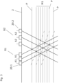
- FIG. 3 outlines a network of crossing points, which is spanned by a first group G1 of connected first ultrasonic transducers with three first ultrasonic transducers 20.1 and by a second group G2 of connected second ultrasonic transducers with three second ultrasonic transducers 20.2.
- the network would have the shape of a rhombus, with some crossing points being at the same distance from a wall of the measuring tube 2 . Due to different distances A1 and A2, the rhombus is distorted, i.e. a parallelogram, so that crossing points with otherwise the same distance to a measuring tube wall are now each arranged along a straight line inclined to the measuring tube wall, as indicated by the dashed lines.
- the distances between the parallels and the ultrasonic transducers depend on the distance between the first group and the second group. Pushing the second group closer to the first group results in a reduction in the distances between the parallels and the ultrasonic transducers. In this case, the arrangement could be used on measuring tubes with a small diameter.
- the first group of first ultrasonic transducers G1 comprising the ultrasonic transducers U1 to U2 and the second group of ultrasonic transducers G2 comprising the ultrasonic transducers U4 to U6 clamp according to 3 a network of crossing points, with crossing points occupying a first set M1 of equidistant parallels P, and with crossing points occupying parallels P which do not belong to set M1.
- the gap between a parallel not belonging to set M1 and a parallel belonging to set M1 is one integer multiple of neighboring parallels of the set M1.
- the set M1 can be expanded by means of at least a third group of ultrasonic transducers G3, for example comprising the ultrasonic transducer U7 and/or the ultrasonic transducers U8 and U9, as shown by the parallel lines shown in dashed lines.
- the same can also be extended to ultrasonic transducer arrangements in which the first group of ultrasonic transducers and/or the second group of ultrasonic transducers have more than three ultrasonic transducers.
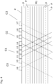
- FIG. 5 outlines ultrasonic signal paths depending on the measuring tube diameter. Ultrasonic signals, which are radiated into the measuring tube on a first side of the measuring tube 2.11, are reflected on a second side of the measuring tube 2.12 on an inside of the measuring tube wall.
- the ultrasonic signal paths of the ultrasonic transducers U2 and U4 are offset from one another, which results in a reduced ultrasonic signal amplitude in the receiving ultrasonic transducer. This is indicated by the thick dashed lines for an ultrasonic signal originating from U4.
- the inside of the second side of the measuring tube lies between the parallels P1 and P2 and is equidistant from both parallels, there is a maximum relevant deviation of the inside wall from one of the parallels P1 and P2. If the inner wall were closer to P1, the ultrasonic signal paths of ultrasonic transducers U2 and U4 would be more closely matched. If the inner wall were closer to P2, the ultrasonic signal paths of ultrasonic transducers U1 and U3 would be more closely matched. This is demonstrated by means of the thin dashed lines starting from U3 to U1 and starting from U4 to U2, which sketch an ultrasonic signal width neglecting a widening that occurs in practice. When reflected on the inner wall running exactly between P1 and P2, the Ultrasonic signals are no longer centered on the corresponding receiving ultrasonic transducer but offset, with the offset being the same for both ultrasonic signal paths.
- the arrangement has a third group G3 of ultrasonic transducers with a first ultrasonic transducer 20.1 and a second ultrasonic transducer 20.2, by means of which the most powerful set of equidistant parallels as in 4 is outlined.
- the ultrasonic transducer arrangement can have a third ultrasonic transducer 20.3, which is set up to emit ultrasonic signals perpendicular to the measuring tube axis and then receive them on the second side 2.12 after reflection on the inside of the measuring tube.
- a third ultrasonic transducer 20.3 which is set up to emit ultrasonic signals perpendicular to the measuring tube axis and then receive them on the second side 2.12 after reflection on the inside of the measuring tube.
- the carrier body can have positioning elements, by means of which the ultrasonic transducers can be positioned in a desired position during installation in the carrier body. After positioning, the ultrasonic transducers can be cast in the carrier body.
- the ultrasonic transducers can be held individually in the carrier body, for example, so that an adaptation to a rough or uneven measuring tube surface, for example, is possible. This sketch is to be interpreted as an example and not as a restriction with regard to the number and arrangement of the ultrasonic transducers.
- a clamp-on ultrasonic flowmeter does not have to have a curvature sensor.
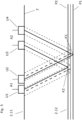
- a curvature sensor has a distance sensor 4.1 and a spacer 4.2, which spacer has a central area 4.21 and two ends 4.22 angled from the central area. The spacer is placed on the measuring tube parallel to a measuring tube cross-section of the measuring tube 2, the central region having a distance from an outer surface of the measuring tube that depends on the outer diameter of the measuring tube. This distance is measured with the distance sensor 4.1 installed in the central area.
- a sensor can be an ultrasonic sensor or an optical sensor, for example.
- W-shaped signal paths with two reflections on the second side of the measuring tube and an intermediate reflection on the first side of the measuring tube 2.11 can also be selected. This can be advantageous in the case of small measuring tube diameters or when measuring tube vibrations caused by ultrasonic signal coupling are temporally superimposed upon arrival at an ultrasonic transducer intended for reception with ultrasonic signals which run along a V-shaped ultrasonic signal path.
- a pair of ultrasonic transducers comprising a first ultrasonic transducer and a second ultrasonic transducer.
- a measuring tube inner diameter and a measuring tube wall thickness can be determined by means of a third ultrasonic transducer, and a pair of ultrasonic transducers can thereby be determined.
- a curvature sensor can also be used as an alternative or in addition.
- a plurality of first and/or second ultrasonic transducers can emit ultrasonic signals at the same time or at different times.
- a selection of an ultrasonic transducer pair can then be determined, for example, based on an ultrasonic signal amplitude, which is measured by means of ultrasonic transducers intended for reception.
- different ultrasonic transducers used to emit ultrasonic signals can each impress one or more features on the ultrasonic signals.
- a center frequency be characteristic.
- ultrasonic signals can have different signal chirps.
- a medium can also be fed through the measuring tube and a transit time difference measurement of ultrasonic signals can be carried out.
- Ultrasonic signals with no transit time difference or with a transit time difference that is too small can be excluded from consideration.
- Such signals are, for example, signals which are coupled into the measuring tube from an original ultrasonic signal without passing through the medium.
- a receiving ultrasonic transducer starting from an original ultrasonic signal, a plurality of ultrasonic signals caused by different reflections can therefore arrive in a temporally superimposed or temporally offset manner.
Description
Clamp-On-Ultraschall-Durchflussmessstellen werden anstelle von Inline-Durchflussmessstellen mit in einem Messrohr integrierten Ultraschallwandlern eingesetzt, wenn ein Einbau eines Messrohrs einer Inline-Durchflussmessstelle umständlich oder unmöglich ist. Clamp-On-Ultraschall-Durchflussmessstellen sind deutlich einfacher einzurichten und an verschiedenen Messrohren einsetzbar, weisen jedoch den Nachteil auf, dass Ultraschallwandler einer solchen Messstelle ab Werk allenfalls grob aufeinander eingestellt werden können.Clamp-on ultrasonic flow measuring points are used instead of inline flow measuring points with ultrasonic transducers integrated in a measuring tube if installing a measuring tube of an inline flow measuring point is cumbersome or impossible. Clamp-on ultrasonic flow measuring points are much easier to set up and can be used on different measuring tubes, but have the disadvantage that the ultrasonic transducers of such a measuring point can at best be roughly adjusted to one another ex works.
Der Stand der Technik zeigt Ultraschallwandleranordnungen von solchen Durchflussmessstellen, bei welchen die Ultraschallwandler verschiebbar zueinander eingerichtet sind, um eine Feineinstellung durchführen zu können. Dies erfordert jedoch Fachkenntnisse und auch einen gewissen Zeitaufwand. Eine Umgehung dieser Problematik wird in der
Aufgabe der Erfindung ist es, eine Ultraschallwandleranordnung einer Clamp-On Ultraschall-Durchflussmessstelle und eine Clamp-On-Ultraschall-Durchflussmessstelle vorzuschlagen, bei welcher die Ultraschallwandleranordnung weitgehend unabhängig von einem Messrohrdurchmesser einsetzbar ist.The object of the invention is to propose an ultrasonic transducer arrangement of a clamp-on ultrasonic flow measurement point and a clamp-on ultrasonic flow measurement point, in which the ultrasonic transducer arrangement can be used largely independently of a measuring tube diameter.
Die Aufgabe wird gelöst durch eine Ultraschallwandleranordnung gemäß dem unabhängigen Anspruch 1, sowie einer Clamp-On-Ultraschall-Durchflussmessstellegemäß dem unabhängigen Anspruch 7.The object is solved by an ultrasonic transducer arrangement according to
Eine erfindungsgemäße Ultraschallwandleranordnung einer Clamp-On-Ultraschall-Durchflussmessstelle basierend auf dem Laufzeitdifferenzenprinzip umfasst:
- mehrere Ultraschallwandler, welche dazu eingerichtet sind, auf einer Außenseite eines Messrohrs der Clamp-On-Durchflussmessstelle angeordnet zu werden,
- wobei die Ultraschallwandler jeweils mindestens ein Wandlerelement zum Erzeugen und/oder
- Empfangen von Ultraschallsignalen sowie ein Koppelelement aufweisen, wobei das Koppelelement eine erste Kontaktfläche und eine zweite Kontaktfläche aufweist, wobei das Wandlerelement auf der ersten Kontaktfläche angeordnet ist, und wobei der Ultraschallwandler dazu eingerichtet ist, mittels der zweiten Kontaktfläche mit dem Messrohr kontaktiert zu werden,
- wobei die Ultraschallwandler dazu eingerichtet sind, Ultraschallsignale in das Messrohr einzustrahlen und/oder aus dem Messrohr austretende Ultraschallsignale zu aufzunehmen,
- wobei die zweiten Kontaktflächen jeweils eine Normale aufweisen, wobei die Normalen eine Ebene definieren, in welcher Ebene Ultraschallsignalpfade der Ultraschallsignale verlaufen,
- wobei erste Ultraschallwandler parallel zueinander verlaufende erste Ultraschallsignalpfade definieren, und wobei zweite Ultraschallwandler parallel zueinander verlaufende zweite Ultraschallsignalpfade definieren, wobei die Ultraschallsignalpfade in der Ebene verlaufen,
- wobei die Ultraschallsignalpfade der ersten Ultraschallwandler sowie der zweiten Ultraschallwandler im Koppelelement jeweils schräg zur zweiten Kontaktfläche verlaufen,
- wobei eine Richtung der ersten Ultraschallsignalpfade und eine Richtung der zweiten Ultraschallsignalpfade spiegelsymmetrisch zu einer der Normalen sind,
- wobei erste Ultraschallsignalpfade mit zweiten Ultraschallsignalpfaden Kreuzungspunkte in der Ebene definieren, wobei die Kreuzungspunkte Parallelen besetzen, welche Parallelen in der Ebene senkrecht zu den Normalen verlaufen,
- wobei eine erste Gruppe zusammenhängender Ultraschallwandler ausschließlich erste Ultraschallwandler mit einer ersten Anzahl aufweist, und wobei eine zweite Gruppe zusammenhängender Ultraschallwandler ausschließlich zweite Ultraschallwandler mit einer zweiten Anzahl aufweist,
- wobei benachbarte Ultraschallwandler der ersten Gruppe in Richtung der Parallelen jeweils erste Abstände A1 zueinander aufweisen, und wobei benachbarte Ultraschallwandler der zweiten Gruppe in Richtung der Parallelen jeweils zweite Abstände A2 zueinander aufweisen, wobei der erste Abstand und der zweite Abstand ungleich sind,
- dadurch gekennzeichnet, dass
- 2*A1 >= A2 >= 1.125*A1, und insbesondere 1.75*A1 >= A2 >= 1.16*A1, und bevorzugt 1.6*A1 >= A2 >= 1.25*A1.
- several ultrasonic transducers, which are set up to be arranged on the outside of a measuring tube of the clamp-on flow measuring point,
- wherein the ultrasonic transducers each generate at least one transducer element and/or
- Receiving ultrasonic signals and having a coupling element, wherein the coupling element has a first contact surface and a second contact surface, wherein the transducer element is arranged on the first contact surface, and the ultrasonic transducer is set up to be in contact with the measuring tube by means of the second contact surface,
- wherein the ultrasonic transducers are set up to radiate ultrasonic signals into the measuring tube and/or to record ultrasonic signals emerging from the measuring tube,
- wherein the second contact surfaces each have a normal, wherein the normals define a plane in which plane ultrasonic signal paths of the ultrasonic signals run,
- wherein first ultrasonic transducers define first ultrasonic signal paths running parallel to one another, and wherein second ultrasonic transducers define second ultrasonic signal paths running parallel to one another, the ultrasonic signal paths running in the same plane,
- wherein the ultrasonic signal paths of the first ultrasonic transducers and the second ultrasonic transducers in the coupling element each run at an angle to the second contact surface,
- wherein a direction of the first ultrasonic signal paths and a direction of the second ultrasonic signal paths are mirror-symmetrical to one of the normals,
- wherein first ultrasonic signal paths define crossing points with second ultrasonic signal paths in the plane, the crossing points occupying parallels which parallels are in the plane perpendicular to the normals,
- wherein a first group of contiguous ultrasonic transducers has exclusively first ultrasonic transducers with a first number, and wherein a second group of contiguous ultrasonic transducers exclusively has second ultrasonic transducers with a second number,
- wherein adjacent ultrasonic transducers of the first group have first distances A1 from one another in the direction of the parallels, and wherein adjacent ultrasonic transducers of the second group have second distances A2 from one another in the direction of the parallels, the first distance and the second distance being unequal,
- characterized in that
- 2*A1 >= A2 >= 1.125*A1, and in particular 1.75*A1 >= A2 >= 1.16*A1, and preferably 1.6*A1 >= A2 >= 1.25*A1.
Zusammenhängend bedeutet, dass zwischen Ultraschallwandlern einer Gruppe keine weiteren Ultraschallwandler angeordnet sind.Connected means that no further ultrasonic transducers are arranged between ultrasonic transducers of a group.
Die vorliegende Erfindung entspricht ein Zusammenhang zwischen erstem Abstand A1 und zweitem Abstand A2 nach folgender Gleichung:
(a+1)*A1 =a*A2 mit b > a > 1, a natürliche Zahl und b kleiner 9, und insbesondere kleiner 7, und bevorzugt kleiner 5.The present invention corresponds to a relationship between the first distance A1 and the second distance A2 according to the following equation:
(a+1)*A1=a*A2 with b>a>1, a natural number and b less than 9, and in particular less than 7, and preferably less than 5.
Vorteilhaft ist die erste Anzahl und/oder die zweite Anzahl größer a.The first number and/or the second number is advantageously greater than a.
In einer Ausgestaltung weisen die Ultraschallwandler jeweils eine Längsachse auf, wobei die Längsachse jeweils einen Innenwinkel α zur entsprechenden zweiten Kontaktfläche aufweisen, wobei der Ultraschallsignalpfad im Koppelelement entlang der Längsachse verläuft, ![]()
![]()
![]()
![]()
In einer Ausgestaltung weist die Ultraschallwandleranordnung mindestens eine dritte Gruppe Ultraschallwandler mit zumindest einen ersten Ultraschallwandler und/oder zumindest einen zweiten Ultraschallwandler auf,
wobei mindestens ein mit einem ersten Ultraschallwandler der dritten Gruppe und/oder mit einem zweiten Ultraschallwandler der dritten Gruppe gebildeter Kreuzungspunkt eine mächtigste erste Menge äquidistanter Parallelen erweitert.In one configuration, the ultrasonic transducer arrangement has at least a third group of ultrasonic transducers with at least one first ultrasonic transducer and/or at least one second ultrasonic transducer,
at least one crossing point formed with a first ultrasonic transducer of the third group and/or with a second ultrasonic transducer of the third group extends a most powerful first set of equidistant parallels.
Die mächtigste erste Menge ist dadurch gekennzeichnet, dass benachbarte Parallelen zugehörig zur mächtigsten Menge jeweils einen gleichen Abstand zueinander aufweisen und dass die Menge im Vergleich zu anderen Mengen äquidistanter Parallelen die meisten Parallelen aufweist.The most powerful first set is characterized in that neighboring parallels belonging to the most powerful set are each equidistant from one another and that the set has the most parallels compared to other sets of equidistant parallels.
In einer Ausgestaltung umfasst die Ultraschallwandleranordnung zumindest einen dritten Ultraschallwandler, welcher einen Signalpfad aufweist, welcher senkrecht zur zweiten Kontaktfläche verläuft.In one configuration, the ultrasonic transducer arrangement comprises at least one third ultrasonic transducer, which has a signal path which runs perpendicularly to the second contact surface.
In einer Ausgestaltung weist die Anordnung einen Trägerkörper zum Halten der Ultraschallwandler auf.In one configuration, the arrangement has a carrier body for holding the ultrasonic transducer.
In einer Ausgestaltung sind die Ultraschallwandler im Trägerkörper jeweils einzeln gehalten.In one embodiment, the ultrasonic transducers are each held individually in the carrier body.
Eine erfindungsgemäße Clamp-On-Ultraschall-Durchflussmessstelle zum Messen einer Durchflussgeschwindigkeit eines durch ein Messrohr strömenden Mediums umfasst:
- das Messrohr zum Führen eines Mediums mit einer Messrohrachse,
- eine erfindungsgemäße Ultraschallwandleranordnung, wobei die Ultraschallwandleranordnung parallel zur Messrohrachse ausgerichtet ist,
- eine elektronische Mess- und Betriebsschaltung zum Betreiben der Ultraschallwandler sowie zum Ermitteln und Bereitstellen von Messwerten der Durchflussgeschwindigkeit.
- the measuring tube for guiding a medium with a measuring tube axis,
- an ultrasonic transducer arrangement according to the invention, wherein the ultrasonic transducer arrangement is aligned parallel to the measuring tube axis,
- an electronic measuring and operating circuit for operating the ultrasonic transducer and for determining and providing measured values of the flow rate.
In einer Ausgestaltung umfasst die Clamp-On-Ultraschall-Durchflussmessstelle einen Krümmungssensor zur Bestimmung eines Außendurchmessers des Messrohrs,
- wobei der Krümmungssensor einen Abstandssensor und einen Abstandshalter aufweist,
- wobei der Abstandshalter einen Zentralbereich und zwei an den Zentralbereich anschließende Enden aufweist, wobei die Enden durch eine Biegung oder einen Knick oder einen Winkel vom Zentralbereich abgegrenzt sind,
- wobei der Abstandshalter dazu eingerichtet ist, mittels der Enden mit dem Messrohr kontaktiert zu werden, wobei der Zentralbereich dazu eingerichtet ist, vom Messrohr beabstandet zu sein, und
- wobei ein Querschnitt bzw. Längsschnitt durch den Abstandshalter durch beide Enden dazu eingerichtet ist, parallel zu einem Messrohrquerschnitt zu verlaufen,
- wobei der Abstandssensor im Zentralbereich am Abstandshalter angeordnet ist,
- wobei die elektronische Mess-/Betriebsschaltung dazu eingerichtet ist, den Abstandssensor zu betreiben.
- wherein the curvature sensor has a distance sensor and a spacer,
- wherein the spacer has a central area and two ends adjoining the central area, the ends being delimited from the central area by a bend or a kink or an angle,
- wherein the spacer is configured to be in contact with the measuring tube by means of the ends, wherein the central region is configured to be spaced apart from the measuring tube, and
- wherein a cross section or longitudinal section through the spacer through both ends is set up to run parallel to a measuring tube cross section,
- wherein the distance sensor is arranged in the central area on the spacer,
- wherein the electronic measuring/operating circuit is configured to operate the distance sensor.
In einer Ausgestaltung ist der Abstandssensor ein optischer oder akustischer Abstandssensor.In one configuration, the distance sensor is an optical or acoustic distance sensor.
Bei einem Verfahren zur Inbetriebnahme der Clamp-On-Ultraschall-Durchflussmessstelle, welches Verfahren nicht Teil von dem Gegenstand der Ansprüche ist, senden mehrere erste Ultraschallwandler / mehrere zweite Ultraschallwandler gleichzeitig oder zeitlich versetzt jeweils ein Ultraschallsignal aus, welche von zweiten Ultraschallwandlern / ersten Ultraschallwandlern empfangen werden,
wobei die elektronische Mess-/Betriebsschaltung anhand von Signalstärke und/oder Signal/Rauschen-Verhältnis der empfangenen Ultraschallsignale zumindest ein für einen Messbetrieb zu verwendendes Ultraschallwandlerpaar bestimmt.In a method for commissioning the clamp-on ultrasonic flow measuring point, which method is not part of the subject matter of the claims, several first ultrasonic transducers/several second ultrasonic transducers emit an ultrasonic signal simultaneously or at different times, which is received by second ultrasonic transducers/first ultrasonic transducers become,
wherein the electronic measuring/operating circuit uses the signal strength and/or signal/noise ratio of the received ultrasonic signals to determine at least one pair of ultrasonic transducers to be used for a measuring operation.
In einer Ausgestaltung, nicht Teil von dem Gegenstand der Ansprüche ist, sind die Ultraschallsignale quasikontinuierlich und sich in ihrer Frequenz unterscheiden,
oder wobei die Ultraschallsignale gepulst sind und sich in folgendem Merkmal unterscheiden:
Zentralfrequenz eines Frequenzspektrums.In one embodiment, which is not part of the subject matter of the claims, the ultrasonic signals are quasi-continuous and differ in frequency,
or where the ultrasonic signals are pulsed and differ in the following characteristic:
Center frequency of a frequency spectrum.
In einer Ausgestaltung, nicht Teil von dem Gegenstand der Ansprüche ist, wird ein Medium durch das Messrohr geführt,
- wobei bei empfangenen Ultraschallsignalen Ultraschallsignalanteile auf ein Vorhandensein einer Laufzeitdifferenz untersucht werden,
- wobei Ultraschallsignalanteile ohne Laufzeitdifferenz bei der Bestimmung eines zu verwendenden Ultraschallwandlerpaars ausgeschlossen werden.
- where, in the case of received ultrasonic signals, ultrasonic signal components are examined for the presence of a transit time difference,
- wherein ultrasonic signal components without transit time difference are excluded when determining a pair of ultrasonic transducers to be used.
Bei einem Verfahren, das nicht Teil von dem Gegenstand der Ansprüche ist, wird der dritte Ultraschallwandler dazu veranlasst, ein Ultraschallsignal auszusenden und zu empfangen,
- wobei die elektronische Mess-/Betriebsschaltung einen Außendurchmesser und/oder Innendurchmesser anhand von mindestens einer Signaleigenschaft des empfangenen Ultraschallsignals bestimmt,
- wobei nutzbare Signaleigenschaften beispielsweise sind:
Laufzeit.
- wherein the electronic measuring/operating circuit determines an outer diameter and/or inner diameter based on at least one signal property of the received ultrasonic signal,
- where usable signal properties are for example:
Duration.
Bei einem Verfahren, das nicht Teil von dem Gegenstand der Ansprüche ist, bestimmt die elektronische Mess-/Betriebsschaltung einen Außendurchmesser mittels des Krümmungssensors zur Bestimmung eines Außendurchmessers.In a method which is not part of the subject matter of the claims, the electronic measurement/operation circuit determines an outer diameter using the curvature sensor for determining an outer diameter.
Im Folgenden wird die Erfindung anhand von Ausführungsbeispielen beschrieben.
-
Fig. 1 skizziert zwei Ultraschallwandler einer erfindungsgemäßen Anordnung; -
Fig. 2 skizziert geometrische Zusammenhänge einer erfindungsgemäßen Anordnung von Ultraschallwandlern; -
Fig. 3 skizziert eine Verteilung von Kreuzungspunkten; -
Fig. 4 skizziert Ergänzungsmöglichkeiten einer mächtigsten ersten Menge äquidistanter Parallelen; -
Fig. 5 skizziert verschiedene Ultraschallsignalpfade in einem Messrohr in Abhängigkeit von einem Messrohrdurchmesser; -
Fig. 6 skizziert eine beispielhafte erfindungsgemäße Anordnung von Ultraschallwandlern; -
Fig. 7 skizziert eine Anordnung in einem Trägerkörper; -
Fig. 8 skizziert eine Durchflussmessstelle mit einer erfindungsgemäßen Anordnung; -
Fig. 9 skizziert einen Krümmungssensor.
-
1 outlines two ultrasonic transducers of an arrangement according to the invention; -
2 outlines the geometric relationships of an arrangement of ultrasonic transducers according to the invention; -
3 outlines a distribution of crossing points; -
4 outlines possible additions to a most powerful first set of equidistant parallels; -
figure 5 outlines different ultrasonic signal paths in a measuring tube depending on a measuring tube diameter; -
6 outlines an exemplary arrangement of ultrasonic transducers according to the invention; -
7 outlines an arrangement in a carrier body; -
8 outlines a flow measuring point with an arrangement according to the invention; -
9 sketches a curvature sensor.
Typische Werte für den Winkel γ sind 30° bis 45° abhängig von den für das Koppelement sowie Messrohr verwendeten Materialien und vom durch das Messrohr strömenden Medium.Typical values for the angle γ are 30° to 45° depending on the materials used for the coupling element and the measuring tube and on the medium flowing through the measuring tube.
Die Anzahlen der Ultraschallwandler, ihre Anordnungen zueinander sowie die gewählten Winkel sind nicht einschränkend auszulegen und haben einen rein darstellerischen Zweck. Eine hier vemachlässigte Wandstärke des Messrohrs 2 beeinflusst einen Schalleintrittspunkt in das Medium relativ zum Koppelelement. Ein Fachmann wird dies gegebenenfalls berücksichtigen.The number of ultrasonic transducers, their mutual arrangement and the selected angles are not to be interpreted as limiting and are purely for representational purposes. one here Neglected wall thickness of the measuring
Die Abstände der Parallelen zu den Ultraschallwandlern sind abhängig von einem Abstand der ersten Gruppe zur zweiten Gruppe. Ein Heranschieben der zweiten Gruppe an die erste Gruppe hat eine Verringerung der Abstände der Parallelen zu den Ultraschallwandlern zur Folge. In diesem Fall könnte die Anordnung an Messrohren mit kleinem Durchmesser eingesetzt werden.The distances between the parallels and the ultrasonic transducers depend on the distance between the first group and the second group. Pushing the second group closer to the first group results in a reduction in the distances between the parallels and the ultrasonic transducers. In this case, the arrangement could be used on measuring tubes with a small diameter.
Die Anzahlen der Ultraschallwandler, ihre Anordnungen zueinander sowie die gewählten Winkel sind nicht einschränkend auszulegen und haben einen rein darstellerischen Zweck.The number of ultrasonic transducers, their mutual arrangement and the selected angles are not to be interpreted as limiting and are purely for representational purposes.
Entsprechendes lässt sich auch auf Ultraschallwandleranordnungen erweitern, bei welchen die erste Gruppe Ultraschallwandler und/oder die zweite Gruppe Ultraschallwandler mehr als drei Ultraschallwandler aufweisen.The same can also be extended to ultrasonic transducer arrangements in which the first group of ultrasonic transducers and/or the second group of ultrasonic transducers have more than three ultrasonic transducers.
Für den Fall, dass die Innenseite des Messrohrs der zweiten Seite nicht mit einer Parallelen P1 zusammenfällt, sind Ultraschallsignalpfade der Ultraschallwandler U2 und U4 zueinander versetzt, was bei dem jeweils empfangenden Ultraschallwandler eine verminderte Ultraschallsignalamplitude zur Folge hat. Dies ist angedeutet durch die dick gestrichelten Linien für ein Ultraschallsignal ausgehend von U4.In the event that the inside of the measuring tube on the second side does not coincide with a parallel line P1, the ultrasonic signal paths of the ultrasonic transducers U2 and U4 are offset from one another, which results in a reduced ultrasonic signal amplitude in the receiving ultrasonic transducer. This is indicated by the thick dashed lines for an ultrasonic signal originating from U4.
Für den Fall, dass die Innenseite des Messrohrs der zweiten Seite mit einer Parallelen P2 zusammenfällt, überlagern sich die Ultraschallsignalpfade der Ultraschallwandler U1 und U3.In the event that the inside of the measuring tube on the second side coincides with a parallel line P2, the ultrasonic signal paths of the ultrasonic transducers U1 and U3 are superimposed.
Falls die Innenseite der zweiten Seite des Messrohrs zwischen den Parallelen P1 und P2 liegt und gleichweit von beiden Parallelen entfernt ist, liegt eine maximale relevante Abweichung der Innenwand von einer der Parallelen P1 und P2 vor. Falls die Innenwand näher an P1 läge, hätte dies ein besseres Übereinstimmen der Ultraschallsignalpfade der Ultraschallwandler U2 und U4 zur Folge. Falls die Innenwand näher an P2 läge, hätte dies ein besseres Übereinstimmen der Ultraschallsignalpfade der Ultraschallwandler U1 und U3 zur Folge. Dies ist mittels der dünn gestrichelten Linien ausgehend von U3 zu U1 und ausgehend von U4 zu U2 demonstriert, welche unter Vernachlässigung einer praktisch auftretenden Aufweitung eine Ultraschallsignalbreite skizzieren. Bei Reflektion an der exakt zwischen P1 und P2 verlaufenden Innenwand treffen die Ultraschallsignale nicht mehr zentral auf den entsprechenden empfangenden Ultraschallwandler sondern versetzt, wobei der Versatz bei beiden Ultraschallsignalpfaden gleich groß ist.If the inside of the second side of the measuring tube lies between the parallels P1 and P2 and is equidistant from both parallels, there is a maximum relevant deviation of the inside wall from one of the parallels P1 and P2. If the inner wall were closer to P1, the ultrasonic signal paths of ultrasonic transducers U2 and U4 would be more closely matched. If the inner wall were closer to P2, the ultrasonic signal paths of ultrasonic transducers U1 and U3 would be more closely matched. This is demonstrated by means of the thin dashed lines starting from U3 to U1 and starting from U4 to U2, which sketch an ultrasonic signal width neglecting a widening that occurs in practice. When reflected on the inner wall running exactly between P1 and P2, the Ultrasonic signals are no longer centered on the corresponding receiving ultrasonic transducer but offset, with the offset being the same for both ultrasonic signal paths.
Bevorzugt weisen die Wandlerelemente eine radiale Ausdehnung rA (siehe
Eine Ultraschallsignalaufweitung außer Acht lassend hätte eine maximale relevante Abweichung in diesem Fall einen Versatz eines Ultraschallsignalpfads entlang der Messrohrachse bzw. entlang einer Parallelen P von einem Drittel einer Ultraschallsignalbreite parallel zur Messrohrachse zu Folge. Es hat sich gezeigt, dass in diesem Fall eine Ultraschallsignalamplitude bei einem zum Empfang bestimmten Ultraschallwandler noch ausreichend für eine gute Signalverarbeitung ist.Disregarding an ultrasonic signal widening, a maximum relevant deviation in this case would result in an offset of an ultrasonic signal path along the measuring tube axis or along a parallel P of one third of an ultrasonic signal width parallel to the measuring tube axis. It has been shown that in this case an ultrasonic signal amplitude is still sufficient for good signal processing in the case of an ultrasonic transducer intended for reception.
Anstatt der in
Eine Inbetriebnahme der Clamp-On-Ultraschall-Durchflussmessstelle erfordert ein Bestimmen eines Ultraschallwandlerpaars umfassend einen ersten Ultraschallwandler und einen zweiten Ultraschallwandler. Dazu kann wie bereits erwähnt mittels eines dritten Ultraschallwandlers ein Messrohrinnendurchmesser sowie eine Messrohrwandstärke bestimmt werden und dadurch ein Ultraschallwandlerpaar bestimmt werden. Alternativ oder zusätzlich kann auch wie bereits erwähnt ein Krümmungssensor eingesetzt werden. Alternativ oder zusätzlich können mehrere erste und/oder zweite Ultraschallwandler gleichzeitig oder zeitlich versetzt Ultraschallsignale aussenden. Eine Auswahl eines Ultraschallwandlerpaars kann dann beispielsweise anhand einer Ultraschallsignalamplitude, welche mittels zum Empfang bestimmten Ultraschallwandlern gemessen wird, bestimmt werden. Zwecks Unterscheidung können verschiedene zum Aussenden von Ultraschallsignalen verwendete Ultraschallwandler den Ultraschallsignalen jeweils ein oder mehrere Merkmale aufprägen. Beispielsweise kann bei gepulsten Ultraschallsignalen eine Zentralfrequenz charakteristisch sein. Alternativ oder zusätzlich kann beispielsweise können Ultraschallsignale unterschiedlichen Signalchirp aufweisen.Commissioning the clamp-on ultrasonic flow measuring point requires a pair of ultrasonic transducers to be determined, comprising a first ultrasonic transducer and a second ultrasonic transducer. For this purpose, as already mentioned, a measuring tube inner diameter and a measuring tube wall thickness can be determined by means of a third ultrasonic transducer, and a pair of ultrasonic transducers can thereby be determined. As already mentioned, a curvature sensor can also be used as an alternative or in addition. Alternatively or additionally, a plurality of first and/or second ultrasonic transducers can emit ultrasonic signals at the same time or at different times. A selection of an ultrasonic transducer pair can then be determined, for example, based on an ultrasonic signal amplitude, which is measured by means of ultrasonic transducers intended for reception. For the purpose of differentiation, different ultrasonic transducers used to emit ultrasonic signals can each impress one or more features on the ultrasonic signals. For example, in the case of pulsed ultrasonic signals, a center frequency be characteristic. Alternatively or additionally, for example, ultrasonic signals can have different signal chirps.
Bei der Inbetriebnahme kann auch ein Medium durch das Messrohr geführt und eine Laufzeitdifferenzenmessung von Ultraschallsignalen durchgeführt werden. Dabei können Ultraschallsignale ohne oder zu geringer Laufzeitdifferenz von einer Berücksichtigung ausgeschlossen werden. Solche Signale sind beispielsweise Signale, welche von einem ursprünglichen Ultraschallsignal in das Messrohr eingekoppelt werden, ohne das Medium zu durchlaufen. Bei einem empfangenden Ultraschallwandler können also ausgehend von einem ursprünglichen Ultraschallsignal mehrere durch unterschiedliche Reflektionen verursachte Ultraschallsignale zeitlich überlagert oder zeitlich versetzt eintreffen.During commissioning, a medium can also be fed through the measuring tube and a transit time difference measurement of ultrasonic signals can be carried out. Ultrasonic signals with no transit time difference or with a transit time difference that is too small can be excluded from consideration. Such signals are, for example, signals which are coupled into the measuring tube from an original ultrasonic signal without passing through the medium. In the case of a receiving ultrasonic transducer, starting from an original ultrasonic signal, a plurality of ultrasonic signals caused by different reflections can therefore arrive in a temporally superimposed or temporally offset manner.
- 11
- Clamp-On-Ultraschall-DurchflussmessstelleClamp-on ultrasonic flow measurement junction
- 22
- Messrohrmeasuring tube
- 2.112.11
- erste Messrohrseitefirst measuring tube side
- 2.122.12
- zweite Messrohrseitesecond measuring tube side
- 2.22.2
- Messrohrachsemeasuring tube axis
- 33
- elektronische Mess-/Betriebsschaltungelectronic measurement/operation circuit
- 44
- Krümmungssensorcurvature sensor
- 4.14.1
- Abstandssensordistance sensor
- 4.24.2
- Abstandshalterspacers
- 4.214.21
- Zentralbereichcentral area
- 4.224.22
- EndeEnd
- 1010
- Ultraschallwandleranordnungultrasonic transducer assembly
- 2020
- Ultraschallwandlerultrasonic transducer
- 20.120.1
- erster Ultraschallwandlerfirst ultrasonic transducer
- 20.220.2
- zweiter Ultraschallwandlersecond ultrasonic transducer
- 20.320.3
- dritter Ultraschallwandlerthird ultrasonic transducer
- 2121
- Wandlerelementtransducer element
- 2222
- Koppelelementcoupling element
- 22.122.1
- erste Kontaktflächefirst contact surface
- 22.222.2
- zweite Kontaktflächesecond contact surface
- 3030
- Trägerkörpercarrier body
- Anz1number1
- erste Anzahlfirst number
- Anz2number2
- zweite Anzahlsecond number
- M1M1
- erste Mengefirst lot
- A1A1
- erster Abstandfirst distance
- A2A2
- zweiter Abstandsecond distance
- UP1UP1
- erster Ultraschallsignalpfadfirst ultrasonic signal path
- UP2UP2
- zweiter Ultraschallsignalpfadsecond ultrasonic signal path
- K1, K2K1, K2
- Kreuzungspunktcrossing point
- NN
- Normalenormal
- U1 - U9U1 - U9
- Ultraschallwandlerultrasonic transducer
- G1G1
- erste Gruppefirst group
- G2G2
- zweite Gruppesecond group
- G3G3
- dritte Gruppethird group
- PP
- Paralleleparallel
Claims (9)
- An ultrasonic transducer arrangement (10) for a clamp-on ultrasonic flow measuring point (1) based on the travel time difference principle, comprising:a plurality of ultrasonic transducers (20) which are adapted to be arranged on an outside of a measuring tube (2) of the clamp-on flow measuring point,wherein the ultrasonic transducers (20) each have at least one transducer element (21) for generating and/or receiving ultrasonic signals and a coupling element (22), wherein the coupling element has a first contact area (22.1) and a second contact area (22.2), wherein the transducer element is arranged on the first contact area, and wherein the ultrasonic transducer is adapted to come into contact with the measuring tube by means of the second contact area,wherein the ultrasonic transducers are adapted to radiate ultrasonic signals into the measuring tube and/or to receive ultrasonic signals coming from the measuring tube,wherein the second contact areas each have a normal (N), wherein the normals define a plane, in which plane ultrasonic signal paths of the ultrasonic signals run,wherein first ultrasonic transducers (20.1) define first ultrasonic signal paths (UP1) running parallel to one another, and wherein second ultrasonic transducers (20.2) define second ultrasonic signal paths (UP2) running parallel to one another, wherein the ultrasonic signal paths run in the plane,wherein the ultrasonic signal paths of the first ultrasonic transducers and of the second ultrasonic transducers in the coupling element each run obliquely to the second contact area,wherein a direction of the first ultrasonic signal paths and a direction of the second ultrasonic signal paths are mirror-symmetric to one of the normals,wherein first ultrasonic signal paths have crossing points (KP) with second ultrasonic signal path in the plane, wherein the crossing points possess parallels (P), which parallels run perpendicularly to the normals in the plane,wherein a first group (G1) of associated ultrasonic transducers exclusively has first ultrasonic transducers with a first number (Anz1), and wherein a second group (G2) of associated ultrasonic transducers has exclusively second ultrasonic transducers with a second number (Anz2),wherein adjacent ultrasonic transducers of the first group are each first distances (A1) from one another in the direction of the parallels, and wherein adjacent ultrasonic transducers of the second group are each second distances (A2) from one another in the direction of the parallels, wherein the first distance and the second distance are not the same,wherein2∗A1 >= A2 >= 1.125∗A1, and in particular 1.75∗A1 >= A2 >= 1.16∗A1, and preferably 1.6∗A1 >= A2 >= 1.25∗A1,wherein a relationship between the first distance (A1) and the second distance (A2) corresponds to the following equation:
(a+1)∗A1=a∗A2 where b > a > 1, a is a natural number and b is less than 9, and in particular less than 7, and preferably less than 5. - The ultrasonic transducer arrangement as claimed in claim 1,wherein the coupling elements each have a longitudinal axis (L), wherein the longitudinal axis in each case has an internal angle (α) to the corresponding second contact area, wherein the ultrasonic signal path in the coupling element runs along the longitudinal axis,wherein the transducer elements have a radial expansion (rA), wherein
 and in particular
- The ultrasonic transducer arrangement as claimed in claim 1 or 2,wherein the ultrasonic transducer arrangement has at least one third group (G3) of ultrasonic transducers with at least one first ultrasonic transducer and/or at least one second ultrasonic transducer,wherein at least one crossing point formed with a first ultrasonic transducer of the third group and/or with a second ultrasonic transducer of the third group extends a most powerful first quantity (M1) of equidistant parallels.
- The ultrasonic transducer arrangement as claimed in one of the preceding claims,
comprising at least one third ultrasonic transducer (20.3) which has a signal path which runs perpendicularly to the second contact area. - The ultrasonic transducer arrangement as claimed in one of the preceding claims,
wherein the arrangement is held by a support body (30), which support body is adapted to position and hold the ultrasonic transducers. - The ultrasonic transducer arrangement as claimed in claim 5,
wherein the ultrasonic transducers are each held individually in the support body. - A clamp-on ultrasonic flow measuring point (1) for measuring a flow speed of a medium flowing through a measuring tube (2) comprising:the measuring tube (2) for guiding a medium with a measuring tube axis (2.1),an ultrasonic transducer arrangement (10) as claimed in one of the preceding claims, wherein the ultrasonic transducer arrangement is configured parallel to the measuring tube axis,an electronic measuring/operating circuit (3) for operation of the ultrasonic transducers and for determining and providing measurement values of the flow speed.
- The clamp-on ultrasonic flow measuring point as claimed in claim 7,comprising a curvature sensor (4) for determining an external diameter of the measuring tube,wherein the curvature sensor has a distance sensor (4.1) and a spacer (4.2),wherein the spacer has a central region (4.21) and two ends (4.22) adjoining the central region, wherein the ends are delimited from the central region by a bend or a kink or an angle,wherein the spacer is adapted to be brought into contact with the measuring tube by means of the ends, wherein the central region is adapted to be spaced apart from the measuring tube, and wherein a cross section or longitudinal section through the spacer through both ends is adapted to run parallel to a measuring tube cross section,wherein the distance sensor is arranged in the central region on the spacer,wherein the electronic measuring/operating circuit (3) is adapted to operate the distance sensor.
- The clamp-on ultrasonic flow measuring point as claimed in claim 8,
wherein the distance sensor is an optical or acoustic distance sensor.
Applications Claiming Priority (2)
| Application Number | Priority Date | Filing Date | Title |
|---|---|---|---|
| DE102018132053.1A DE102018132053B4 (en) | 2018-12-13 | 2018-12-13 | Ultrasonic transducer assembly of a clamp-on ultrasonic flowmeter, and a clamp-on ultrasonic flowmeter and methods for commissioning the clamp-on ultrasonic flowmeter |
| PCT/EP2019/082015 WO2020120091A1 (en) | 2018-12-13 | 2019-11-21 | Ultrasonic transducer arrangement for a clamp-on ultrasonic flow measuring point and a clamp-on ultrasonic flow measuring point and method for putting the clamp-on ultrasonic flow measuring point into operation |
Publications (2)
| Publication Number | Publication Date |
|---|---|
| EP3894800A1 EP3894800A1 (en) | 2021-10-20 |
| EP3894800B1 true EP3894800B1 (en) | 2023-08-09 |
Family
ID=68654480
Family Applications (1)
| Application Number | Title | Priority Date | Filing Date |
|---|---|---|---|
| EP19808759.5A Active EP3894800B1 (en) | 2018-12-13 | 2019-11-21 | Ultrasonic transducer arrangement for a clamp-on ultrasonic flow measuring point and a clamp-on ultrasonic flow measuring point and method for putting the clamp-on ultrasonic flow measuring point into operation |
Country Status (5)
| Country | Link |
|---|---|
| US (1) | US11835372B2 (en) |
| EP (1) | EP3894800B1 (en) |
| CN (1) | CN113167619A (en) |
| DE (1) | DE102018132053B4 (en) |
| WO (1) | WO2020120091A1 (en) |
Families Citing this family (1)
| Publication number | Priority date | Publication date | Assignee | Title |
|---|---|---|---|---|
| DE102018133476B4 (en) * | 2018-12-21 | 2023-11-02 | Endress+Hauser Flowtec Ag | Method for commissioning and/or checking a clamp-on ultrasonic flow measuring point |
Family Cites Families (11)
| Publication number | Priority date | Publication date | Assignee | Title |
|---|---|---|---|---|
| DE59000807D1 (en) * | 1989-05-09 | 1993-03-11 | Flowtec Ag | ULTRASONIC FLOW MEASURING DEVICE. |
| EP0686255B1 (en) | 1993-12-23 | 2000-03-15 | Endress + Hauser Flowtec AG | Clamp-on ultrasonic volume flow rate measuring device |
| WO2000060317A1 (en) * | 1999-04-01 | 2000-10-12 | Panametrics, Inc. | Clamp-on ultrasonic flow meter for low density fluids |
| EP1483545B1 (en) * | 2002-03-13 | 2006-06-21 | Borealis Technology Oy | Apparatus for inspecting deformation of pipes |
| DE102004053673A1 (en) * | 2004-11-03 | 2006-05-04 | Endress + Hauser Flowtec Ag | Device for determining and / or monitoring the volume and / or mass flow rate of a medium |
| GB0620944D0 (en) * | 2006-10-20 | 2006-11-29 | Insensys Ltd | Curvature measurement moving relative to pipe |
| DE102008002166A1 (en) * | 2008-06-03 | 2009-12-10 | Endress + Hauser Flowtec Ag | Measuring system for determining and / or monitoring the flow of a measuring medium through a measuring tube |
| DE102008029772A1 (en) | 2008-06-25 | 2009-12-31 | Endress + Hauser Flowtec Ag | Method and measuring system for determining and / or monitoring the flow of a measuring medium through a measuring tube |
| JP5985311B2 (en) * | 2012-08-30 | 2016-09-06 | Ntn株式会社 | Bearing track groove measuring device and bearing track groove measuring method |
| FR3003646B1 (en) * | 2013-03-21 | 2015-04-03 | V & M France | DEVICE AND METHOD FOR NON-DESTRUCTIVE CONTROL OF TUBULAR PRODUCTS, ESPECIALLY ON SITE |
| GB2521661A (en) * | 2013-12-27 | 2015-07-01 | Xsens As | Apparatus and method for measuring flow |
-
2018
- 2018-12-13 DE DE102018132053.1A patent/DE102018132053B4/en active Active
-
2019
- 2019-11-21 US US17/413,266 patent/US11835372B2/en active Active
- 2019-11-21 CN CN201980081321.XA patent/CN113167619A/en active Pending
- 2019-11-21 WO PCT/EP2019/082015 patent/WO2020120091A1/en unknown
- 2019-11-21 EP EP19808759.5A patent/EP3894800B1/en active Active
Also Published As
| Publication number | Publication date |
|---|---|
| CN113167619A (en) | 2021-07-23 |
| DE102018132053A1 (en) | 2020-06-18 |
| US11835372B2 (en) | 2023-12-05 |
| US20220049983A1 (en) | 2022-02-17 |
| DE102018132053B4 (en) | 2022-08-25 |
| EP3894800A1 (en) | 2021-10-20 |
| WO2020120091A1 (en) | 2020-06-18 |
Similar Documents
| Publication | Publication Date | Title |
|---|---|---|
| EP1936333B1 (en) | Ultrasound flow measuring device | |
| EP1554549B1 (en) | Flowmeter | |
| EP3267159B1 (en) | Ultrasound measuring device and method for measuring the flow speed of a liquid in a pipeline | |
| EP2386835B1 (en) | Ultrasound measurement of the flow speed of a fluid in a tubular conduit | |
| EP1931948B1 (en) | Device for determining or monitoring a medium volume or mass flow rate in a conduit | |
| DE102017110308A1 (en) | Ultrasonic flowmeter | |
| EP0566859B1 (en) | Ultrasonic flowmeter with helical measuring channel | |
| EP2072972A1 (en) | Device for measuring the movement of a fluid in a pipe | |
| EP3894799B1 (en) | Ultrasound transducer arrangement of a clamp-on ultrasound flow measuring unit, and a clamp-on ultrasound flow measuring unit and method for starting up the clamp-on ultrasound flow measuring unit | |
| EP3894800B1 (en) | Ultrasonic transducer arrangement for a clamp-on ultrasonic flow measuring point and a clamp-on ultrasonic flow measuring point and method for putting the clamp-on ultrasonic flow measuring point into operation | |
| DE102006047526A1 (en) | Current rectifier for use in device for measuring flow rate and/or flow of e.g. gas, has conducting surfaces running in elongation of radius of fastening cylinder, so that star shaped arrangement is formed, where surfaces have through-holes | |
| EP3940346A1 (en) | Flow meter and method for measuring the flow rate of a fluid | |
| EP0080640B1 (en) | Method and device for the determination of bubbles in a fluid | |
| DE102018110495B4 (en) | Coriolis measuring sensor with a measuring tube torsion compensating sensor group and a Coriolis measuring device with such a measuring sensor | |
| EP3268954B1 (en) | Arrangement and field device for process measurement technology | |
| EP3521774A1 (en) | Ultrasound flow meter and method for determining the flow speed | |
| EP3855134B1 (en) | Device for measuring the flow speed of a fluid | |
| DE102020126021A1 (en) | Fluid measuring device | |
| EP2511673A1 (en) | Method for measuring flow volumes according to the principle of ultrasound transit time | |
| EP3748309A1 (en) | Ultrasound flow measuring device, blocking device and use in a blocking device | |
| DE102013005810A1 (en) | Method for operating an ultrasonic measuring arrangement and ultrasonic measuring arrangement | |
| EP4047328A1 (en) | Ultrasonic flow meter and method for determining the velocity of a flowing medium | |
| DE10235033A1 (en) | Ultrasound fluid mass flowmeter has a sound path that is independent of the fluid flow channel enabling the sound to be routed so that it avoids areas of turbulence or flow inhomogeneities | |
| EP3748310B1 (en) | Ultrasound flow measuring device | |
| DE102021133188A1 (en) | Method for operating an ultrasonic measuring device and an ultrasonic measuring device |
Legal Events
| Date | Code | Title | Description |
|---|---|---|---|
| STAA | Information on the status of an ep patent application or granted ep patent |
Free format text: STATUS: UNKNOWN |
|
| STAA | Information on the status of an ep patent application or granted ep patent |
Free format text: STATUS: THE INTERNATIONAL PUBLICATION HAS BEEN MADE |
|
| PUAI | Public reference made under article 153(3) epc to a published international application that has entered the european phase |
Free format text: ORIGINAL CODE: 0009012 |
|
| STAA | Information on the status of an ep patent application or granted ep patent |
Free format text: STATUS: REQUEST FOR EXAMINATION WAS MADE |
|
| 17P | Request for examination filed |
Effective date: 20210507 |
|
| AK | Designated contracting states |
Kind code of ref document: A1 Designated state(s): AL AT BE BG CH CY CZ DE DK EE ES FI FR GB GR HR HU IE IS IT LI LT LU LV MC MK MT NL NO PL PT RO RS SE SI SK SM TR |
|
| DAV | Request for validation of the european patent (deleted) | ||
| DAX | Request for extension of the european patent (deleted) | ||
| REG | Reference to a national code |
Ref country code: DE Ref legal event code: R079 Ref document number: 502019008909 Country of ref document: DE Free format text: PREVIOUS MAIN CLASS: G01F0001660000 Ipc: G01F0001667000 Ref country code: DE Ref legal event code: R079 Free format text: PREVIOUS MAIN CLASS: G01F0001660000 Ipc: G01F0001667000 |
|
| GRAP | Despatch of communication of intention to grant a patent |
Free format text: ORIGINAL CODE: EPIDOSNIGR1 |
|
| STAA | Information on the status of an ep patent application or granted ep patent |
Free format text: STATUS: GRANT OF PATENT IS INTENDED |
|
| RIC1 | Information provided on ipc code assigned before grant |
Ipc: G01F 1/667 20220101AFI20230221BHEP |
|
| INTG | Intention to grant announced |
Effective date: 20230322 |
|
| GRAS | Grant fee paid |
Free format text: ORIGINAL CODE: EPIDOSNIGR3 |
|
| GRAA | (expected) grant |
Free format text: ORIGINAL CODE: 0009210 |
|
| STAA | Information on the status of an ep patent application or granted ep patent |
Free format text: STATUS: THE PATENT HAS BEEN GRANTED |
|
| AK | Designated contracting states |
Kind code of ref document: B1 Designated state(s): AL AT BE BG CH CY CZ DE DK EE ES FI FR GB GR HR HU IE IS IT LI LT LU LV MC MK MT NL NO PL PT RO RS SE SI SK SM TR |
|
| REG | Reference to a national code |
Ref country code: GB Ref legal event code: FG4D Free format text: NOT ENGLISH |
|
| REG | Reference to a national code |
Ref country code: CH Ref legal event code: EP |
|
| REG | Reference to a national code |
Ref country code: DE Ref legal event code: R096 Ref document number: 502019008909 Country of ref document: DE |
|
| REG | Reference to a national code |
Ref country code: IE Ref legal event code: FG4D Free format text: LANGUAGE OF EP DOCUMENT: GERMAN |
|
| REG | Reference to a national code |
Ref country code: NL Ref legal event code: FP |
|
| REG | Reference to a national code |
Ref country code: LT Ref legal event code: MG9D |
|
| P01 | Opt-out of the competence of the unified patent court (upc) registered |
Effective date: 20231027 |
|
| PGFP | Annual fee paid to national office [announced via postgrant information from national office to epo] |
Ref country code: NL Payment date: 20231120 Year of fee payment: 5 |
|
| PG25 | Lapsed in a contracting state [announced via postgrant information from national office to epo] |
Ref country code: GR Free format text: LAPSE BECAUSE OF FAILURE TO SUBMIT A TRANSLATION OF THE DESCRIPTION OR TO PAY THE FEE WITHIN THE PRESCRIBED TIME-LIMIT Effective date: 20231110 |
|
| PGFP | Annual fee paid to national office [announced via postgrant information from national office to epo] |
Ref country code: GB Payment date: 20231123 Year of fee payment: 5 |
|
| PG25 | Lapsed in a contracting state [announced via postgrant information from national office to epo] |
Ref country code: IS Free format text: LAPSE BECAUSE OF FAILURE TO SUBMIT A TRANSLATION OF THE DESCRIPTION OR TO PAY THE FEE WITHIN THE PRESCRIBED TIME-LIMIT Effective date: 20231209 |
|
| PG25 | Lapsed in a contracting state [announced via postgrant information from national office to epo] |
Ref country code: SE Free format text: LAPSE BECAUSE OF FAILURE TO SUBMIT A TRANSLATION OF THE DESCRIPTION OR TO PAY THE FEE WITHIN THE PRESCRIBED TIME-LIMIT Effective date: 20230809 Ref country code: RS Free format text: LAPSE BECAUSE OF FAILURE TO SUBMIT A TRANSLATION OF THE DESCRIPTION OR TO PAY THE FEE WITHIN THE PRESCRIBED TIME-LIMIT Effective date: 20230809 Ref country code: PT Free format text: LAPSE BECAUSE OF FAILURE TO SUBMIT A TRANSLATION OF THE DESCRIPTION OR TO PAY THE FEE WITHIN THE PRESCRIBED TIME-LIMIT Effective date: 20231211 Ref country code: NO Free format text: LAPSE BECAUSE OF FAILURE TO SUBMIT A TRANSLATION OF THE DESCRIPTION OR TO PAY THE FEE WITHIN THE PRESCRIBED TIME-LIMIT Effective date: 20231109 Ref country code: LV Free format text: LAPSE BECAUSE OF FAILURE TO SUBMIT A TRANSLATION OF THE DESCRIPTION OR TO PAY THE FEE WITHIN THE PRESCRIBED TIME-LIMIT Effective date: 20230809 Ref country code: LT Free format text: LAPSE BECAUSE OF FAILURE TO SUBMIT A TRANSLATION OF THE DESCRIPTION OR TO PAY THE FEE WITHIN THE PRESCRIBED TIME-LIMIT Effective date: 20230809 Ref country code: IS Free format text: LAPSE BECAUSE OF FAILURE TO SUBMIT A TRANSLATION OF THE DESCRIPTION OR TO PAY THE FEE WITHIN THE PRESCRIBED TIME-LIMIT Effective date: 20231209 Ref country code: HR Free format text: LAPSE BECAUSE OF FAILURE TO SUBMIT A TRANSLATION OF THE DESCRIPTION OR TO PAY THE FEE WITHIN THE PRESCRIBED TIME-LIMIT Effective date: 20230809 Ref country code: GR Free format text: LAPSE BECAUSE OF FAILURE TO SUBMIT A TRANSLATION OF THE DESCRIPTION OR TO PAY THE FEE WITHIN THE PRESCRIBED TIME-LIMIT Effective date: 20231110 Ref country code: FI Free format text: LAPSE BECAUSE OF FAILURE TO SUBMIT A TRANSLATION OF THE DESCRIPTION OR TO PAY THE FEE WITHIN THE PRESCRIBED TIME-LIMIT Effective date: 20230809 |
|
| PGFP | Annual fee paid to national office [announced via postgrant information from national office to epo] |
Ref country code: FR Payment date: 20231120 Year of fee payment: 5 Ref country code: DE Payment date: 20231121 Year of fee payment: 5 Ref country code: CZ Payment date: 20231110 Year of fee payment: 5 |
|
| PG25 | Lapsed in a contracting state [announced via postgrant information from national office to epo] |
Ref country code: PL Free format text: LAPSE BECAUSE OF FAILURE TO SUBMIT A TRANSLATION OF THE DESCRIPTION OR TO PAY THE FEE WITHIN THE PRESCRIBED TIME-LIMIT Effective date: 20230809 |