EP3894773B1 - Unterwasserkühleranordnungen - Google Patents
Unterwasserkühleranordnungen Download PDFInfo
- Publication number
- EP3894773B1 EP3894773B1 EP19896531.1A EP19896531A EP3894773B1 EP 3894773 B1 EP3894773 B1 EP 3894773B1 EP 19896531 A EP19896531 A EP 19896531A EP 3894773 B1 EP3894773 B1 EP 3894773B1
- Authority
- EP
- European Patent Office
- Prior art keywords
- pipe support
- support beam
- brackets
- holes
- cooler
- Prior art date
- Legal status (The legal status is an assumption and is not a legal conclusion. Google has not performed a legal analysis and makes no representation as to the accuracy of the status listed.)
- Active
Links
Images


Classifications
-
- F—MECHANICAL ENGINEERING; LIGHTING; HEATING; WEAPONS; BLASTING
- F28—HEAT EXCHANGE IN GENERAL
- F28F—DETAILS OF HEAT-EXCHANGE AND HEAT-TRANSFER APPARATUS, OF GENERAL APPLICATION
- F28F9/00—Casings; Header boxes; Auxiliary supports for elements; Auxiliary members within casings
- F28F9/007—Auxiliary supports for elements
- F28F9/013—Auxiliary supports for elements for tubes or tube-assemblies
-
- E—FIXED CONSTRUCTIONS
- E21—EARTH OR ROCK DRILLING; MINING
- E21B—EARTH OR ROCK DRILLING; OBTAINING OIL, GAS, WATER, SOLUBLE OR MELTABLE MATERIALS OR A SLURRY OF MINERALS FROM WELLS
- E21B36/00—Heating, cooling or insulating arrangements for boreholes or wells, e.g. for use in permafrost zones
- E21B36/001—Cooling arrangements
-
- F—MECHANICAL ENGINEERING; LIGHTING; HEATING; WEAPONS; BLASTING
- F16—ENGINEERING ELEMENTS AND UNITS; GENERAL MEASURES FOR PRODUCING AND MAINTAINING EFFECTIVE FUNCTIONING OF MACHINES OR INSTALLATIONS; THERMAL INSULATION IN GENERAL
- F16L—PIPES; JOINTS OR FITTINGS FOR PIPES; SUPPORTS FOR PIPES, CABLES OR PROTECTIVE TUBING; MEANS FOR THERMAL INSULATION IN GENERAL
- F16L3/00—Supports for pipes, cables or protective tubing, e.g. hangers, holders, clamps, cleats, clips, brackets
- F16L3/08—Supports for pipes, cables or protective tubing, e.g. hangers, holders, clamps, cleats, clips, brackets substantially surrounding the pipe, cable or protective tubing
- F16L3/085—Supports for pipes, cables or protective tubing, e.g. hangers, holders, clamps, cleats, clips, brackets substantially surrounding the pipe, cable or protective tubing for pipes being in an angled relationship to each other
-
- F—MECHANICAL ENGINEERING; LIGHTING; HEATING; WEAPONS; BLASTING
- F16—ENGINEERING ELEMENTS AND UNITS; GENERAL MEASURES FOR PRODUCING AND MAINTAINING EFFECTIVE FUNCTIONING OF MACHINES OR INSTALLATIONS; THERMAL INSULATION IN GENERAL
- F16L—PIPES; JOINTS OR FITTINGS FOR PIPES; SUPPORTS FOR PIPES, CABLES OR PROTECTIVE TUBING; MEANS FOR THERMAL INSULATION IN GENERAL
- F16L3/00—Supports for pipes, cables or protective tubing, e.g. hangers, holders, clamps, cleats, clips, brackets
- F16L3/16—Supports for pipes, cables or protective tubing, e.g. hangers, holders, clamps, cleats, clips, brackets with special provision allowing movement of the pipe
- F16L3/18—Supports for pipes, cables or protective tubing, e.g. hangers, holders, clamps, cleats, clips, brackets with special provision allowing movement of the pipe allowing movement in axial direction
-
- F—MECHANICAL ENGINEERING; LIGHTING; HEATING; WEAPONS; BLASTING
- F16—ENGINEERING ELEMENTS AND UNITS; GENERAL MEASURES FOR PRODUCING AND MAINTAINING EFFECTIVE FUNCTIONING OF MACHINES OR INSTALLATIONS; THERMAL INSULATION IN GENERAL
- F16L—PIPES; JOINTS OR FITTINGS FOR PIPES; SUPPORTS FOR PIPES, CABLES OR PROTECTIVE TUBING; MEANS FOR THERMAL INSULATION IN GENERAL
- F16L3/00—Supports for pipes, cables or protective tubing, e.g. hangers, holders, clamps, cleats, clips, brackets
- F16L3/22—Supports for pipes, cables or protective tubing, e.g. hangers, holders, clamps, cleats, clips, brackets specially adapted for supporting a number of parallel pipes at intervals
- F16L3/223—Supports for pipes, cables or protective tubing, e.g. hangers, holders, clamps, cleats, clips, brackets specially adapted for supporting a number of parallel pipes at intervals each support having one transverse base for supporting the pipes
- F16L3/2235—Supports for pipes, cables or protective tubing, e.g. hangers, holders, clamps, cleats, clips, brackets specially adapted for supporting a number of parallel pipes at intervals each support having one transverse base for supporting the pipes each pipe being supported by a common element fastened to the base
-
- F—MECHANICAL ENGINEERING; LIGHTING; HEATING; WEAPONS; BLASTING
- F16—ENGINEERING ELEMENTS AND UNITS; GENERAL MEASURES FOR PRODUCING AND MAINTAINING EFFECTIVE FUNCTIONING OF MACHINES OR INSTALLATIONS; THERMAL INSULATION IN GENERAL
- F16L—PIPES; JOINTS OR FITTINGS FOR PIPES; SUPPORTS FOR PIPES, CABLES OR PROTECTIVE TUBING; MEANS FOR THERMAL INSULATION IN GENERAL
- F16L3/00—Supports for pipes, cables or protective tubing, e.g. hangers, holders, clamps, cleats, clips, brackets
- F16L3/22—Supports for pipes, cables or protective tubing, e.g. hangers, holders, clamps, cleats, clips, brackets specially adapted for supporting a number of parallel pipes at intervals
- F16L3/223—Supports for pipes, cables or protective tubing, e.g. hangers, holders, clamps, cleats, clips, brackets specially adapted for supporting a number of parallel pipes at intervals each support having one transverse base for supporting the pipes
- F16L3/227—Supports for pipes, cables or protective tubing, e.g. hangers, holders, clamps, cleats, clips, brackets specially adapted for supporting a number of parallel pipes at intervals each support having one transverse base for supporting the pipes each pipe being supported by a separate element fastened to the base
-
- F—MECHANICAL ENGINEERING; LIGHTING; HEATING; WEAPONS; BLASTING
- F16—ENGINEERING ELEMENTS AND UNITS; GENERAL MEASURES FOR PRODUCING AND MAINTAINING EFFECTIVE FUNCTIONING OF MACHINES OR INSTALLATIONS; THERMAL INSULATION IN GENERAL
- F16L—PIPES; JOINTS OR FITTINGS FOR PIPES; SUPPORTS FOR PIPES, CABLES OR PROTECTIVE TUBING; MEANS FOR THERMAL INSULATION IN GENERAL
- F16L3/00—Supports for pipes, cables or protective tubing, e.g. hangers, holders, clamps, cleats, clips, brackets
- F16L3/22—Supports for pipes, cables or protective tubing, e.g. hangers, holders, clamps, cleats, clips, brackets specially adapted for supporting a number of parallel pipes at intervals
- F16L3/237—Supports for pipes, cables or protective tubing, e.g. hangers, holders, clamps, cleats, clips, brackets specially adapted for supporting a number of parallel pipes at intervals for two pipes
-
- F—MECHANICAL ENGINEERING; LIGHTING; HEATING; WEAPONS; BLASTING
- F16—ENGINEERING ELEMENTS AND UNITS; GENERAL MEASURES FOR PRODUCING AND MAINTAINING EFFECTIVE FUNCTIONING OF MACHINES OR INSTALLATIONS; THERMAL INSULATION IN GENERAL
- F16L—PIPES; JOINTS OR FITTINGS FOR PIPES; SUPPORTS FOR PIPES, CABLES OR PROTECTIVE TUBING; MEANS FOR THERMAL INSULATION IN GENERAL
- F16L57/00—Protection of pipes or objects of similar shape against external or internal damage or wear
- F16L57/06—Protection of pipes or objects of similar shape against external or internal damage or wear against wear
-
- F—MECHANICAL ENGINEERING; LIGHTING; HEATING; WEAPONS; BLASTING
- F16—ENGINEERING ELEMENTS AND UNITS; GENERAL MEASURES FOR PRODUCING AND MAINTAINING EFFECTIVE FUNCTIONING OF MACHINES OR INSTALLATIONS; THERMAL INSULATION IN GENERAL
- F16L—PIPES; JOINTS OR FITTINGS FOR PIPES; SUPPORTS FOR PIPES, CABLES OR PROTECTIVE TUBING; MEANS FOR THERMAL INSULATION IN GENERAL
- F16L58/00—Protection of pipes or pipe fittings against corrosion or incrustation
- F16L58/18—Protection of pipes or pipe fittings against corrosion or incrustation specially adapted for pipe fittings
-
- F—MECHANICAL ENGINEERING; LIGHTING; HEATING; WEAPONS; BLASTING
- F28—HEAT EXCHANGE IN GENERAL
- F28D—HEAT-EXCHANGE APPARATUS, NOT PROVIDED FOR IN ANOTHER SUBCLASS, IN WHICH THE HEAT-EXCHANGE MEDIA DO NOT COME INTO DIRECT CONTACT
- F28D1/00—Heat-exchange apparatus having stationary conduit assemblies for one heat-exchange medium only, the media being in contact with different sides of the conduit wall, in which the other heat-exchange medium is a large body of fluid, e.g. domestic or motor car radiators
- F28D1/02—Heat-exchange apparatus having stationary conduit assemblies for one heat-exchange medium only, the media being in contact with different sides of the conduit wall, in which the other heat-exchange medium is a large body of fluid, e.g. domestic or motor car radiators with heat-exchange conduits immersed in the body of fluid
- F28D1/0206—Heat exchangers immersed in a large body of liquid
- F28D1/022—Heat exchangers immersed in a large body of liquid for immersion in a natural body of water, e.g. marine radiators
-
- F—MECHANICAL ENGINEERING; LIGHTING; HEATING; WEAPONS; BLASTING
- F28—HEAT EXCHANGE IN GENERAL
- F28D—HEAT-EXCHANGE APPARATUS, NOT PROVIDED FOR IN ANOTHER SUBCLASS, IN WHICH THE HEAT-EXCHANGE MEDIA DO NOT COME INTO DIRECT CONTACT
- F28D1/00—Heat-exchange apparatus having stationary conduit assemblies for one heat-exchange medium only, the media being in contact with different sides of the conduit wall, in which the other heat-exchange medium is a large body of fluid, e.g. domestic or motor car radiators
- F28D1/02—Heat-exchange apparatus having stationary conduit assemblies for one heat-exchange medium only, the media being in contact with different sides of the conduit wall, in which the other heat-exchange medium is a large body of fluid, e.g. domestic or motor car radiators with heat-exchange conduits immersed in the body of fluid
- F28D1/04—Heat-exchange apparatus having stationary conduit assemblies for one heat-exchange medium only, the media being in contact with different sides of the conduit wall, in which the other heat-exchange medium is a large body of fluid, e.g. domestic or motor car radiators with heat-exchange conduits immersed in the body of fluid with tubular conduits
- F28D1/047—Heat-exchange apparatus having stationary conduit assemblies for one heat-exchange medium only, the media being in contact with different sides of the conduit wall, in which the other heat-exchange medium is a large body of fluid, e.g. domestic or motor car radiators with heat-exchange conduits immersed in the body of fluid with tubular conduits the conduits being bent, e.g. in a serpentine or zig-zag
- F28D1/0477—Heat-exchange apparatus having stationary conduit assemblies for one heat-exchange medium only, the media being in contact with different sides of the conduit wall, in which the other heat-exchange medium is a large body of fluid, e.g. domestic or motor car radiators with heat-exchange conduits immersed in the body of fluid with tubular conduits the conduits being bent, e.g. in a serpentine or zig-zag the conduits being bent in a serpentine or zig-zag
-
- F—MECHANICAL ENGINEERING; LIGHTING; HEATING; WEAPONS; BLASTING
- F28—HEAT EXCHANGE IN GENERAL
- F28F—DETAILS OF HEAT-EXCHANGE AND HEAT-TRANSFER APPARATUS, OF GENERAL APPLICATION
- F28F19/00—Preventing the formation of deposits or corrosion, e.g. by using filters or scrapers
- F28F19/02—Preventing the formation of deposits or corrosion, e.g. by using filters or scrapers by using coatings, e.g. vitreous or enamel coatings
-
- F—MECHANICAL ENGINEERING; LIGHTING; HEATING; WEAPONS; BLASTING
- F28—HEAT EXCHANGE IN GENERAL
- F28F—DETAILS OF HEAT-EXCHANGE AND HEAT-TRANSFER APPARATUS, OF GENERAL APPLICATION
- F28F2265/00—Safety or protection arrangements; Arrangements for preventing malfunction
- F28F2265/26—Safety or protection arrangements; Arrangements for preventing malfunction for allowing differential expansion between elements
-
- F—MECHANICAL ENGINEERING; LIGHTING; HEATING; WEAPONS; BLASTING
- F28—HEAT EXCHANGE IN GENERAL
- F28F—DETAILS OF HEAT-EXCHANGE AND HEAT-TRANSFER APPARATUS, OF GENERAL APPLICATION
- F28F2280/00—Mounting arrangements; Arrangements for facilitating assembling or disassembling of heat exchanger parts
- F28F2280/10—Movable elements, e.g. being pivotable
Definitions
- the present invention relates to improved submerged cooler designs for e.g. subsea applications, such as for example in oil and gas production and in offshore wind power grid link platforms, and particularly to a unique pipe support arrangement in a submerged cooler, an improved submerged cooler frame and an improved submerged cooler.
- Document CN 202 674 551 U discloses a pipe support arrangement with support beams, structural beams and a single-bracket solution.
- Passive subsea coolers are usually used, because they are more robust than active subsea coolers.
- the fluid to be cooled e.g. a well flow
- the seawater passes through the common volume at a relatively slow rate due to natural convection, i.e. the seawater rises through the subsea cooler since it is heated by the fluid to be cooled. It is thus difficult to regulate or control the cooling effect of passive subsea coolers.
- the cooler pipes can be made of for example different alloys and/or metals. Some of these alloys and/or metals can show very good resistance against marine bio-fouling and general corrosion.
- the oxide layer that is built up on the surface is soft and cannot withstand abrasion as well as it can be damaged (e.g. mechanically). Sliding between component parts may remove the oxide layer and will increase corrosion rates to an unacceptable level.
- the material is prone to crevice corrosion. This issue must be addressed in the interface between the pipe support of the submerged cooler and the cooler piping.
- the pipe support beams of the submerged cooler are long and structural integrity is dominated by deformations.
- the submerged cooler can see loading during its lifespan up to 5G.
- the input header of the cooler piping is stiff, as such the stiffness of the pipe support beams must be large to reduce loading on the cooler piping. Therefore, this issue must also be addressed.
- Another object of the invention is to counteract corrosion of the structure and the piping of the submerged cooler as a consequence of abrasion of the oxide layer thereon.
- Yet another object of the invention is to enable unobstructed inflow of cold seawater through the submerged cooler or to improve the inflow amount of cold seawater through the submerged cooler.
- Yet another object of the invention is to ensure sufficient structural integrity of the submerged cooler.
- Yet another object of the invention is to ensure sufficient protection of the submerged cooler and particularly its piping against vibration and shock loads.
- Yet another object of the invention is to use pipe support beams that are not welded to the frame of the submerged cooler, which in turn will change and ease the fabrication method.
- this is achieved with submerged cooler designs and/or arrangements which alleviate at least some of the disadvantages of the prior art subsea or submersible coolers.
- this is achieved with a unique pipe support of a submerged cooler.
- this is achieved with an improved submerged cooler frame.
- this is achieved with an improved submerged cooler.
- the present invention concerns a pipe support arrangement of a structural frame for a submerged cooler.
- the pipe support arrangement comprises at least one pipe support beam and at least one structural beam of the structural frame.
- Said at least one pipe support beam is configured for carrying approximately perpendicularly arranged cooler piping for the submerged cooler.
- Each structural beam comprises at least one first bracket and at least one second bracket.
- the first and second brackets are firmly arranged onto the structural beam.
- the first and second brackets are configured for receiving inbetween the pipe support beam.
- the pipe support beam is supported and hold by the brackets.
- the pipe support beam is approximately perpendicular to the structural beam.
- the pipe support beam is also moveably arranged inbetween the brackets.
- the pipe support arrangement further comprises limitation means.
- the limitation means is/are configured for securing a predetermined limited translation of the pipe support beam in longitudinal direction with respect to the cooler piping.
- the surfaces of the brackets in contact with the pipe support beam and the surfaces of the pipe support beam in contact with the brackets can be polished and/or treated in such a way so that the limited longitudinal translation of the pipe support is made easier.
- the pipe support arrangement can comprise a first bracket plate, a second bracket plate, a first support plate and a second support plate.
- the first bracket plate can be firmly arranged onto the first bracket.
- the first bracket plate can have a sliding surface facing the pipe support beam.
- the first support plate can be firmly arranged onto one side of the pipe support beam.
- the first support plate can have a sliding surface facing the first bracket.
- the second bracket plate can be firmly arranged onto the second bracket.
- the second bracket plate can have a sliding surface facing the pipe support beam.
- the second support plate can be firmly arranged onto the other side of the pipe support beam.
- the second support plate can have a sliding surface facing the second bracket.
- the plates can be made of a material having a low coefficient of friction. Additionally and/or alternatively, the sliding surfaces of the plates can be treated to get a low coefficient of friction. Thus, the limited longitudinal translation of the pipe support will be eased.
- the limitation means comprises at least one lip.
- Each lip can be firmly arranged on each longitudinal side of each of the brackets.
- the lips can be configured for securing the predetermined limited translation of the pipe support beam in the longitudinal direction with respect to the cooler piping.
- the limitation means comprises a restraining means and a group of holes through the pipe support beam, the brackets and optional bracket and support plates.
- the group of holes is parallel to the structural beam.
- Each of the holes of the brackets and the optional bracket plates can be a circular hole, and each of the holes of the pipe support beam and the optional support plates can be a slit hole.
- each of the holes of the pipe support beam and the optional support plates can be a circular hole, and each of the holes of the brackets and the optional bracket plates can be a slit hole.
- the restraining means can be entirely or partially arranged through the group of holes. The restraining means is configured to interact with the slit hole in order to secure the limited translation of the pipe support beam.
- the restraining means can comprise one from the group consisting of:
- the limitation means can in a different embodiment comprise at least one stud firmly fixed or welded to each bracket and/or to the structural beam. Said at least one stud is also configured to interact with at least one slit arranged on the pipe support beam.
- At least one pipe support beam can be approximately perpendicularly arranged in such a way so that said predetermined limited translation of said at least one pipe support beam in longitudinal direction with respect to the cooler piping will be achieved.
- the pipe support arrangement can further comprise insulation.
- the insulation can be at least one of: electrical and/or corrosion resistant. This insulation insulates the pipes from the structural frame and/or the structural beams.
- the insulation can be: i) arranged between the pipes, the pipe support beams and connection U-bolts or clamps, or ii) built into the pipe support beams or their surfaces, or iii) made by selection of insulation material(s) or coating(s) for the plates combined with insulation of the components restricting the longitudinal movement or translation of the pipe support beams.
- the invention concerns also a structural frame of a submerged or submersible cooler comprising at least one pipe support arrangement.
- the invention concerns a submerged or submersible cooler comprising a structural frame comprising at least one pipe support arrangement and a cooler piping.
- the cooler piping comprises several pipes.
- the pipes in a row are running approximately perpendicularly to the pipe support beam of the structural frame.
- the pipes in a row are parallel to each other.
- the pipes can be firmly connected to the pipe support beam.
- the invention concerns a submerged or submersible cooler comprising a structural frame and a cooler piping.
- the structural frame comprises at least one pipe support beam and at least one structural beam.
- Said at least one pipe support beam is configured for carrying approximately perpendicularly arranged cooler piping.
- the pipe support beam is approximately perpendicular to the structural beam.
- the cooler piping comprises several pipes.
- the pipes in a row are running approximately perpendicularly to the pipe support beam.
- the pipes in a row are parallel to each other.
- the pipes can be firmly connected to the pipe support beam.
- Each pipe support beam comprises pipes arranged on both opposite sides thereof.
- one group of parallel pipes when the pipe support beam is horizontal, one group of parallel pipes will be arranged on top of the pipe support beam, and another group of parallel pipes will be suspended under the pipe support beam.
- the pipe support beam will prevent longitudinal seawater flow between those two pipe rows / groups at the pipe support beam location, but the area between two pipe rows / groups arranged respectively on neighboring pipe support beams will be fully open for seawater flow passing therethrough.
- Figure 1 illustrates a submerged cooler 20 comprising a structural frame 1 and a cooler piping 9.
- the frame 1 comprises structural beams 16 and pipe support beams 5, wherein each structural beam 16 is approximately perpendicular to respective pipe support beam(s) 5, and wherein the structural beams of the structural frame 1 are interconnected with the respective pipe support beams of the structural frame 1 as well as with other additional structural beams necessary for achieving a rigid and robust structural frame 1 of the submerged cooler 20.
- the cooler piping 9 is constituted of multiple pipes.
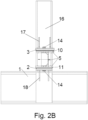
- Figures 2A - 2B show a first solution for longitudinal translation of the pipe support 5 ( figure 2A ) and a detailed view of the sliding faces for longitudinal translation ( figure 2B ).
- a first embodiment of a structural frame 1 of a submerged cooler 20 is shown.
- the structural frame 1 comprises at least one pipe support beam 5 and at least one structural beam 16.
- Each structural beam 16 comprises at least one first bracket 17 and at least one second bracket 18.
- the first and second brackets 17, 18 are firmly arranged on the structural beam 16 in such a way so that the pipe support beam 5 fits moveably inbetween them and is hold by the brackets 17, 18.
- the pipe support beam 5 is approximately perpendicular to the structural beam 16.
- the brackets 17, 18 can be welded onto the structural beam 16.
- the brackets 17, 18 can be firmly fastened to the structural beam 16 by means of for example one or several bolts 22 and optionally nuts (see for example figures 4A-4B ) and/or one or several rivets.
- the pipe support beam 5 is carrying a cooler piping 9.
- the cooler piping 9 comprises several pipes 9.
- the pipes 9 are running approximately perpendicularly to the pipe support beam 5 and are firmly connected thereto, for example by means of welding, U-bolts or clamps 8 and nuts and/or other fastening means.
- the pipes 9 are parallel to each other.
- the pipes 9 of the cooler piping 9 are arranged on one side of each pipe support beam 5; for example on top of each pipe support beam 5. This typical solution for subsea or submerged coolers shows that the cooler pipes are supported by one beam per row or one beam per column.
- some pipes 9 of the cooler piping 9 are arranged on both sides of each pipe support beam 5.
- some pipes 9 of the cooler piping 9 can be arranged on top of each pipe support beam 5, while the rest of pipes 9 of the cooler piping 9 can be suspended under each pipe support beam 5.
- the pipe support beam 5 will prevent longitudinal seawater flow between those two pipe rows at the pipe support beam location, but inbetween every second row is fully open for seawater flow that passes therethrough.
- the latter solution will result in a lower longitudinal projected area of the pipe support beams compared to the first solution, thus allowing more free seawater flow through the cooler 20.
- the surfaces of the brackets 17, 18 in contact with the pipe support beam 5 and the surfaces of the pipe support beam 5 in contact with the brackets 17, 18 can be polished or treated in such a way so that longitudinal translation of the pipe support 5 is being eased.
- a first bracket plate 3 with sliding surface can be firmly arranged onto the first bracket 17 facing the pipe support beam 5.
- a first support plate 10 with sliding surface can be firmly arranged onto the pipe support beam 5 facing the first bracket 17.
- a second bracket plate 2 with sliding surface can be firmly arranged onto the second bracket 18 facing the pipe support beam 5.
- a second support plate 11 with sliding surface can be firmly arranged onto the pipe support beam 5 facing the second bracket 18.
- the plates 2, 3, 10, 11 can be steel plates with a coating or with such a structure that gives low coefficient of friction.
- the arrangement can further comprise electrical insulation, where the pipes 9 are insulated from the structural frame 1 and/or beams 16.
- the electrical insulation can be located between the pipes 9 and the clamps or U-bolts 8 and the pipe support beams 5.
- the electrical insulation can be built into the pipe support beams 5 or their surfaces.
- the electrical insulation can be made by selection of insulation material(s) or coating(s) for the plates 2, 3, 10, 11 combined with insulation of the components restricting the longitudinal movement of the pipe support beams 5.
- the insulation can be corrosion resistant / proof.
- Each one from the group of the brackets 17, 18, the pipe support beam 5 and the optional plates 2, 3, 10, 11 can be arranged with a hole 13, 19 therethrough; the group of holes 13, 19 being parallel to the structural beam 16. At least one restraining bolt 14 and coupling nut 15 can be fastened or installed through the hole(s) 13, 19 and connect the two brackets 17, 18 and the pipe support beam 5.
- the holes 19 of the brackets 17, 18 and the optional bracket plates 2, 3 can be circular holes.
- the hole(s) 13 of the pipe support beam 5 and the optional support plates 10, 11 can be a slit hole allowing for translation of the pipe support beam 5 in longitudinal direction and within desired limits determined by the slit hole. Alternatively, the hole 13 of the pipe support beam 5 can be a circular hole.
- the holes 19 of the brackets 17, 18 can be slit holes. In this case, washers can be used.
- the hole 13 in the pipe support beam 5 can be threaded and two shoulder screws can be used to interface the slit 19 in the brackets 17, 18.
- at least one stud 23 can be firmly fixed or welded to each bracket 17, 18 and/or to the structural beam 16 in order to interact with the slit 13' of the pipe support beam 5.
- the restraining bolt(s) 14 or the like will prevent motion of the pipe support beam 5 in transverse direction.
- suitable fastening means such as but not limited to: rivet(s); a through bolt fixed with a nut on opposite side; a threaded rod with two nuts; two rods with heads inserted from each side and welded together; stud welded into the holes 19 of the brackets 17, 18, etc., can also be used (through the hole(s)), wherein the fastening means is(are) configured for allowing for translation of the pipe support beam 5 within desired limits and in longitudinal direction (see the arrows on figures 2B , 3B , 4B ) and for preventing motion of the pipe support beam 5 in transverse direction.
- two specially made bolts with a threaded middle part and cylindrical end like a reversed shoulder screw can be used. Threading the holes 19 in the brackets 17, 18 allows for installation of these bolts after the pipe support beam 5 is correctly placed between the two brackets 17, 18.
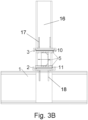
- Figures 3A - 3B show a second solution for longitudinal translation of the pipe support 5 ( figure 3A ) and a detailed view of the sliding faces for longitudinal translation ( figure 3B ).
- a lip 24 can be firmly arranged on each side of each of the brackets 17, 18 in order to allow translation of the pipe support beam 5 in longitudinal direction and within desired limits and to prevent motion of the pipe support beam 5 in transverse direction.
- the lips 24 can be welded, bolted or firmly fastened, by suitable fastening means, to the brackets 17, 18.
- the lips 24 can constitute a part of the brackets 17, 18.
- Figures 4A - 4B show a third solution for longitudinal translation of the pipe support 5 ( figure 4A ) and a detailed view of the sliding faces for longitudinal translation ( figure 4B ).
- the brackets 17, 18 can be firmly fixed to the structural beam 16 by means of bolt(s) 22 and optionally nut(s).
- One of several solutions for use of stud(s) is also shown here, where at least one stud 23 is used for interfacing with a slit 13' for achieving limited longitudinal translation of the pipe support beam 5.
- the fluid to be cooled and running through the pipes 9 can be a coolant fluid (i.e. a special fluid with one or more additives, such as but not limited to different glycols) or water (if necessary with one or more additives thereto) in cases when the submerged cooler is used for offshore electricity production from wind power.
- a coolant fluid i.e. a special fluid with one or more additives, such as but not limited to different glycols
- water if necessary with one or more additives thereto
Landscapes
- Engineering & Computer Science (AREA)
- General Engineering & Computer Science (AREA)
- Mechanical Engineering (AREA)
- Physics & Mathematics (AREA)
- Thermal Sciences (AREA)
- Life Sciences & Earth Sciences (AREA)
- Geology (AREA)
- Mining & Mineral Resources (AREA)
- Ocean & Marine Engineering (AREA)
- Environmental & Geological Engineering (AREA)
- Fluid Mechanics (AREA)
- General Life Sciences & Earth Sciences (AREA)
- Geochemistry & Mineralogy (AREA)
- Supports For Pipes And Cables (AREA)
- Motor Or Generator Cooling System (AREA)
Claims (13)
- Rohrträgeranordnung eines Strukturrahmens (1) eines Tauchkühlers (20), umfassend: i) mindestens einen Rohrträgerbalken (5), der zum Tragen von etwa senkrecht angeordneten Kühlerleitungen (9) für den Tauchkühler (20) konfiguriert ist, und ii) mindestens einen Strukturbalken (16) des Strukturrahmens (1), wobei jeder Strukturbalken (16) mindestens eine erste Halterung (17) und mindestens eine zweite Halterung (18) umfasst, wobei die erste und die zweite Halterung (17, 18) fest auf dem Strukturbalken (16) angeordnet sind und zum Aufnehmen zwischen dem Rohrträgerbalken (5) konfiguriert sind; wobei der Rohrträgerbalken (5) durch die Halterungen (17, 18) gestützt und gehalten wird; wobei der Rohrträgerbalken (5) ungefähr senkrecht zum Strukturbalken (16) verläuft; wobei der Rohrträgerbalken (5) beweglich zwischen den Halterungen (17, 18) angeordnet ist, wobei die Rohrträgeranordnung ferner ein Begrenzungsmittel umfasst, das zum Sichern einer vorbestimmten begrenzten Verschiebung des Rohrträgerbalkens (5) in Längsrichtung in Bezug auf die Kühlerleitungen (9) konfiguriert ist.
- Rohrträgeranordnung nach Anspruch 1, wobei die Oberflächen der Halterungen (17, 18) in Kontakt mit dem Rohrträgerbalken (5) und die Oberflächen des Rohrträgerbalkens (5) in Kontakt mit den Halterungen (17, 18) derart poliert und/oder behandelt sind, dass die begrenzte Längsverschiebung des Rohrträgers (5) erleichtert wird.
- Rohrträgeranordnung nach Anspruch 1, ferner umfassend: i) eine erste Halterungsplatte (3), die fest auf der ersten Halterung (17) angeordnet ist und eine dem Rohrträgerbalken (5) zugewandte Gleitfläche hat; ii) eine erste Stützplatte (10), die fest auf dem Rohrträgerbalken (5) angeordnet ist und eine der ersten Halterung(17) zugewandte Gleitfläche hat; iii) eine zweite Trägerplatte (2), die fest auf der zweiten Halterung (18) angeordnet ist und eine dem Rohrträgerbalken (5) zugewandte Gleitfläche hat; iv) eine zweite Stützplatte (11), die fest auf dem Rohrträgerbalken (5) angeordnet ist und eine der zweiten Halterung (18) zugewandte Gleitfläche hat, wobei die Platten (2, 3, 10, 11) aus einem Material mit einem niedrigen Reibungskoeffizienten hergestellt sind und/oder die Gleitflächen der Platten (2, 3, 10, 11) behandelt werden, um einen niedrigen Reibungskoeffizienten zu erhalten, sodass die begrenzte Längsverschiebung des Rohrträgers (5) erleichtert wird.
- Rohrträgeranordnung gemäß einem der Ansprüche 1-3, wobei das Begrenzungsmittel eine Lippe (24) umfasst, die fest auf jeder Längsseite jeder der Halterungen (17, 18) angeordnet ist und zum Sichern der vorbestimmten begrenzten Verschiebung des Rohrträgerbalkens (5) in Längsrichtung in Bezug auf die Kühlerleitungen (9) konfiguriert ist.
- Rohrträgeranordnung gemäß einem der Ansprüche 1-3, wobei das Begrenzungsmittel ein Rückhaltemittel und eine Gruppe von Löchern (13, 19) durch den Rohrträgerbalken (5), die Halterungen (17, 18) und optionale Halterungs- und Stützplatten (2, 3, 10, 11) umfasst; wobei die Gruppe von Löchern (13, 19) parallel zum Strukturbalken (16) liegt, wobei jedes der Löcher (19) der Halterungen (17, 18) und der optionalen Halterungsplatten (2, 3) ein kreisförmiges Loch ist, und jedes der Löcher (13) des Rohrträgerbalkens (5) und der optionalen Stützplatten (10, 11) ein Schlitzloch ist, wobei das Rückhaltemittel vollständig oder teilweise durch die Gruppe von Löchern (13, 19) angeordnet ist und konfiguriert ist, um mit dem Schlitzloch zusammen zu wirken, um die begrenzte Verschiebung des Rohrträgerbalkens (5) zu sichern.
- Rohrträgeranordnung gemäß einem der Ansprüche 1-3, wobei das Begrenzungsmittel ein Rückhaltemittel und eine Gruppe von Löchern (13, 19) durch den Rohrträgerbalken (5), die Halterungen (17, 18) und optionale Halterungs- und Stützplatten (2, 3, 10, 11) umfasst; wobei die Gruppe von Löchern (13, 19) parallel zum Strukturbalken (16) liegt, wobei jedes der Löcher (13) des Rohrträgerbalkens (5) und der optionalen Stützplatten (10, 11) ein kreisförmiges Loch ist, und jedes der Löcher (19) der Halterungen (17, 18) und der optionalen Halterungsplatten (2, 3) ein Schlitzloch ist, wobei das Rückhaltemittel vollständig oder teilweise durch die Gruppe von Löchern (13, 19) angeordnet ist und konfiguriert ist, um mit dem Schlitzloch zusammen zu wirken, um die begrenzte Verschiebung des Rohrträgerbalkens (5) zu sichern.
- Rohrträgeranordnung gemäß einem der Ansprüche 5-6, wobei das Rückhaltemittel ein Bestandteil der folgenden Gruppe enthält:i) mindestens eine Kopplungsmutter (15) und mindestens einen Rückhaltebolzen (14), die durch einen Teil oder die gesamte Gruppe von Löchern (13, 19) installiert und mit einer jeweiligen Kupplungsmutter (15) befestigt sind, um mit dem Schlitzloch zusammen zu wirken, um die beiden Halterungen (17, 18) und den Rohrträgerbalken (5) beweglich miteinander zu verbinden;ii) mindestens eine Schulterschraube, die konfiguriert ist, um in mindestens ein kreisförmiges Loch mit Gewinden aus der Vielzahl von kreisförmigen Löchern eingefädelt zu werden, und um mit dem Schlitzloch zusammen zu wirken, um die beiden Halterungen (17, 18) und den Rohrträgerbalken (5) beweglich miteinander zu verbinden;iii) mindestens eine Niete, die durch einen Teil oder die gesamte Gruppe von Löchern (13, 19) installiert und konfiguriert ist, um mit dem Schlitzloch zusammen zu wirken und um die beiden Halterungen (17, 18) und den Rohrträgerbalken (5) beweglich miteinander zu verbinden;iv) eine Gewindestange, die durch die Gruppe von Löchern (13, 19) verläuft und mit zwei Kopplungsmuttern auf jeder Seite der Halterungen (17, 18) verbunden ist;v) zwei Stangen mit Köpfen, die von jeder Seite der Halterungen (17, 18) eingeführt und miteinander verschweißt sind;vi) mindestens einen Bolzen, der konfiguriert ist, um mit dem Schlitzloch zusammen zu wirken und fest mit mindestens einem kreisförmigen Loch verbunden oder verschweißt zu werden; und/odervii) zwei Bolzen mit einem Gewindemittelteil und einem zylindrischen Ende wie eine umgekehrte Schulterschraube, wobei die Bolzen so konfiguriert sind, dass sie in Gewindekreislöcher (19) der Halterungen (17, 18) eingefädelt werden und mit dem Schlitzloch (13) des Rohrträgerbalkens (5) zusammenwirken, um die beiden Halterungen (17, 18) und den Rohrträgerbalken (5) beweglich miteinander zu verbinden.
- Rohrträgeranordnung gemäß einem der Ansprüche 1-3, wobei das Begrenzungsmittel mindestens einen Bolzen (23) umfasst, der mit jeder Halterung (17, 18) und/oder mit dem Strukturbalken (16) fest fixiert oder verschweißt ist und konfiguriert ist, um mit mindestens einem Schlitz (13'), der an dem Rohrträgerbalken (5) angeordnet ist, zusammen zu wirken.
- Rohrträgeranordnung gemäß einem der Ansprüche 1-8, wobei zwischen zwei parallelen Strukturträgern (16) mindestens ein Rohrträgerbalken (5) ungefähr derart senkrecht angeordnet ist, dass die vorbestimmte begrenzte Verschiebung des mindestens einen Rohrträgerbalkens (5) in Längsrichtung in Bezug auf die Kühlerleitungen (9) erreicht wird.
- Rohrträgeranordnung gemäß einem der Ansprüche 1-9, die ferner eine Isolierung umfasst, die mindestens eine der folgenden Eigenschaften aufweist: elektrisch und/oder korrosionsbeständig und die Rohre (9) von dem Strukturrahmen (1) und den Strukturträgern (16) isolierend, wobei die Isolierung Folgendes ist: i) zwischen den Rohren (9), den U-Bolzen (8) und den Rohrträgerbalken (5) angeordnet oder ii) in die Rohrträgerbalken (5) oder deren Oberflächen eingebaut, oder iii) durch Auswahl von Isoliermaterial(ien) oder Beschichtung(en) für die Platten (2, 3, 10, 11) hergestellt, die mit der Isolierung der Komponenten, die Längsbewegung oder Verschiebung der Rohrträgerbalken (5) begrenzen.
- Strukturrahmen (1) eines Tauchkühlers (20), umfassend mindestens eine Rohrträgeranordnung gemäß einem der Ansprüche 1-10.
- Tauchkühler (20), umfassend: i) einen Strukturrahmen (1), der mindestens eine Rohrträgeranordnung gemäß einem der Ansprüche 1-9 und ii) eine Kühlerleitungen (9) umfasst, wobei die Kühlerleitungen (9) mehrere Rohre (9) umfassen; wobei die Rohre (9) in einer Reihe verlaufen, die ungefähr senkrecht zu dem Rohrträgerbalken (5) des Strukturrahmens (1) liegt und mit dem Rohrträgerbalken (5) fest verbunden ist; die Rohre (9) in einer Reihe parallel zueinander angeordnet sind.
- Tauchkühler (20) gemäß Anspruch 13, wobei jeder Rohrträgerbalken (5) Rohre (9) umfasst, die auf seinen beiden gegenüberliegenden Seiten angeordnet sind, wobei der Rohrträgerbalken (5) somit eine Längsströmung des Meerwassers zwischen diesen beiden Rohrreihen an der Rohrträgerposition verhindert, aber der Bereich zwischen zwei Rohrreihen, die jeweils an benachbarten Rohrträgerbalken (5) angeordnet sind, für die Strömung des Meerwassers vollständig geöffnet ist.
Applications Claiming Priority (2)
| Application Number | Priority Date | Filing Date | Title |
|---|---|---|---|
| NO20181617A NO344796B1 (en) | 2018-12-14 | 2018-12-14 | Subsea cooler |
| PCT/NO2019/050273 WO2020122733A1 (en) | 2018-12-14 | 2019-12-12 | Submerged cooler arrangements |
Publications (4)
| Publication Number | Publication Date |
|---|---|
| EP3894773A1 EP3894773A1 (de) | 2021-10-20 |
| EP3894773A4 EP3894773A4 (de) | 2022-10-12 |
| EP3894773C0 EP3894773C0 (de) | 2023-07-12 |
| EP3894773B1 true EP3894773B1 (de) | 2023-07-12 |
Family
ID=70726105
Family Applications (1)
| Application Number | Title | Priority Date | Filing Date |
|---|---|---|---|
| EP19896531.1A Active EP3894773B1 (de) | 2018-12-14 | 2019-12-12 | Unterwasserkühleranordnungen |
Country Status (4)
| Country | Link |
|---|---|
| US (1) | US11525639B2 (de) |
| EP (1) | EP3894773B1 (de) |
| NO (1) | NO344796B1 (de) |
| WO (1) | WO2020122733A1 (de) |
Families Citing this family (2)
| Publication number | Priority date | Publication date | Assignee | Title |
|---|---|---|---|---|
| WO2022117129A1 (en) * | 2020-12-01 | 2022-06-09 | Vysoké Učení Technické V Brně | Tubular shell heat exchanger with cross flow |
| CN116331432A (zh) * | 2023-01-28 | 2023-06-27 | 江南造船(集团)有限责任公司 | 一种超大型液化气船液货管系结构以及建造方法 |
Family Cites Families (15)
| Publication number | Priority date | Publication date | Assignee | Title |
|---|---|---|---|---|
| US2198529A (en) * | 1938-12-09 | 1940-04-23 | David E Fields | Heat exchanger |
| US2581121A (en) * | 1947-12-23 | 1952-01-01 | Standard Oil Dev Co | Means for changing baffle pitch in a heat exchanger |
| US4210202A (en) * | 1978-03-30 | 1980-07-01 | Ecolaire Incorporated | Support for heat exchange tubes |
| US4595161A (en) * | 1983-06-01 | 1986-06-17 | Williams George J | Tube bundle support |
| US5052474A (en) * | 1990-10-24 | 1991-10-01 | Bronnert Herve X | Hanger assembly for a multiple tube heat exchanger |
| US6736191B1 (en) * | 2001-10-09 | 2004-05-18 | Power Engineering Contractors, Inc. | Heat exchanger having longitudinal structure and mounting for placement in seawater under piers for heating and cooling of buildings |
| US7651056B2 (en) * | 2005-02-08 | 2010-01-26 | Potential Design, Inc. | Method of mounting support assemblies for pipes, conduits and tubes |
| US20080250579A1 (en) * | 2007-04-10 | 2008-10-16 | Oded Sten | Modular Support Catch System |
| SE535397C2 (sv) | 2009-08-12 | 2012-07-24 | Alfa Laval Corp Ab | En deodoriserare, värmeväxlarsystem innefattande deodoriserare samt förfarande för användning av dess |
| CN202674551U (zh) * | 2012-06-06 | 2013-01-16 | 贵阳铝镁设计研究院有限公司 | 一种活动管架结构 |
| US10100861B2 (en) * | 2014-11-14 | 2018-10-16 | Cooper Technologies Company | Beam clamp for strut channel |
| US20160222761A1 (en) | 2015-01-30 | 2016-08-04 | Bp Corporation North America Inc. | Subsea Heat Exchangers For Offshore Hydrocarbon Production Operations |
| CN204677896U (zh) * | 2015-06-08 | 2015-09-30 | 安徽江淮汽车股份有限公司 | 一种油冷器钢管固定支架总成 |
| GB2548096B (en) * | 2016-03-07 | 2018-08-29 | Empig As | Cooling system |
| CN205806695U (zh) * | 2016-07-01 | 2016-12-14 | 上海金石索泰机电设备有限公司 | 冷却器管道托架结构 |
-
2018
- 2018-12-14 NO NO20181617A patent/NO344796B1/en unknown
-
2019
- 2019-12-12 WO PCT/NO2019/050273 patent/WO2020122733A1/en not_active Ceased
- 2019-12-12 US US17/413,398 patent/US11525639B2/en active Active
- 2019-12-12 EP EP19896531.1A patent/EP3894773B1/de active Active
Also Published As
| Publication number | Publication date |
|---|---|
| EP3894773A1 (de) | 2021-10-20 |
| EP3894773A4 (de) | 2022-10-12 |
| US11525639B2 (en) | 2022-12-13 |
| US20220034604A1 (en) | 2022-02-03 |
| WO2020122733A1 (en) | 2020-06-18 |
| EP3894773C0 (de) | 2023-07-12 |
| NO344796B1 (en) | 2020-04-27 |
Similar Documents
| Publication | Publication Date | Title |
|---|---|---|
| EP3894773B1 (de) | Unterwasserkühleranordnungen | |
| KR101240612B1 (ko) | 선박의 배관 지지 장치 | |
| US8695688B2 (en) | Nubbed U-bend tube support | |
| US20190338482A1 (en) | Method for Vibration Damping of and Vibration Damper Assembly for Semi-Submerged or Submerged Structure | |
| US12559895B2 (en) | Submersible data center mountable on a submersible platform | |
| US8689646B2 (en) | Sealed, slim-line constant force, generation unit | |
| EP3236150A2 (de) | Horizontaler dampferzeuger für eine reaktoranlage | |
| US6736191B1 (en) | Heat exchanger having longitudinal structure and mounting for placement in seawater under piers for heating and cooling of buildings | |
| US20080104838A1 (en) | Anti-vibration support for steam generator heat transfer tubes and method for making same | |
| CA2930654C (en) | Bend stiffener | |
| EP3731610B1 (de) | Wärmeaustauschanordnung und unterwasserelektroniksystem | |
| KR101472302B1 (ko) | 공랭식 가스쿨러용 유밴드형 냉각파이프의 진동방지 서포트 | |
| JP6033123B2 (ja) | 屋外設置用のボイラ、これを備えた船舶、浮体式海上施設 | |
| KR20150001285U (ko) | 덕트설비 및 이를 포함하는 선박 또는 해양구조물 | |
| CN207611617U (zh) | 热分层消除装置及波动管 | |
| JP5153415B2 (ja) | 船舶機関室内における機器の設置構造 | |
| CN223713936U (zh) | 用于海上光伏的光伏组件及其支撑系统 | |
| Hassan et al. | A numerical characterization of flow-induced vibration and fretting wear potential in nuclear steam generator tube bundles | |
| CN222012054U (zh) | 一种长距离栈桥内的采暖系统 | |
| CN216112748U (zh) | 一种供暖管道用补偿器 | |
| CN204784425U (zh) | 设备撬块和硫磺回收设备安装结构 | |
| CN216896106U (zh) | 一种海洋环境中用管夹 | |
| Saunders et al. | Piping Vibration Mitigation Comparison Using Snubbers and Struts | |
| JP6846007B2 (ja) | 加熱管振動防止治具 | |
| ME | Controlling corrosion in marine refrigeration systems |
Legal Events
| Date | Code | Title | Description |
|---|---|---|---|
| STAA | Information on the status of an ep patent application or granted ep patent |
Free format text: STATUS: THE INTERNATIONAL PUBLICATION HAS BEEN MADE |
|
| PUAI | Public reference made under article 153(3) epc to a published international application that has entered the european phase |
Free format text: ORIGINAL CODE: 0009012 |
|
| STAA | Information on the status of an ep patent application or granted ep patent |
Free format text: STATUS: REQUEST FOR EXAMINATION WAS MADE |
|
| 17P | Request for examination filed |
Effective date: 20210621 |
|
| AK | Designated contracting states |
Kind code of ref document: A1 Designated state(s): AL AT BE BG CH CY CZ DE DK EE ES FI FR GB GR HR HU IE IS IT LI LT LU LV MC MK MT NL NO PL PT RO RS SE SI SK SM TR |
|
| DAV | Request for validation of the european patent (deleted) | ||
| DAX | Request for extension of the european patent (deleted) | ||
| A4 | Supplementary search report drawn up and despatched |
Effective date: 20220909 |
|
| RIC1 | Information provided on ipc code assigned before grant |
Ipc: F16L 3/18 20060101ALI20220905BHEP Ipc: F16L 58/18 20060101ALI20220905BHEP Ipc: F16L 3/22 20060101ALI20220905BHEP Ipc: F28F 9/013 20060101AFI20220905BHEP |
|
| GRAP | Despatch of communication of intention to grant a patent |
Free format text: ORIGINAL CODE: EPIDOSNIGR1 |
|
| STAA | Information on the status of an ep patent application or granted ep patent |
Free format text: STATUS: GRANT OF PATENT IS INTENDED |
|
| RIC1 | Information provided on ipc code assigned before grant |
Ipc: F16L 3/18 19680901ALI20230105BHEP Ipc: F16L 58/18 19740701ALI20230105BHEP Ipc: F16L 3/22 19680901ALI20230105BHEP Ipc: F28F 9/013 19950101AFI20230105BHEP |
|
| INTG | Intention to grant announced |
Effective date: 20230201 |
|
| GRAS | Grant fee paid |
Free format text: ORIGINAL CODE: EPIDOSNIGR3 |
|
| GRAA | (expected) grant |
Free format text: ORIGINAL CODE: 0009210 |
|
| STAA | Information on the status of an ep patent application or granted ep patent |
Free format text: STATUS: THE PATENT HAS BEEN GRANTED |
|
| AK | Designated contracting states |
Kind code of ref document: B1 Designated state(s): AL AT BE BG CH CY CZ DE DK EE ES FI FR GB GR HR HU IE IS IT LI LT LU LV MC MK MT NL NO PL PT RO RS SE SI SK SM TR |
|
| REG | Reference to a national code |
Ref country code: CH Ref legal event code: EP |
|
| REG | Reference to a national code |
Ref country code: IE Ref legal event code: FG4D |
|
| REG | Reference to a national code |
Ref country code: DE Ref legal event code: R096 Ref document number: 602019032817 Country of ref document: DE |
|
| U01 | Request for unitary effect filed |
Effective date: 20230809 |
|
| U07 | Unitary effect registered |
Designated state(s): AT BE BG DE DK EE FI FR IT LT LU LV MT NL PT SE SI Effective date: 20230816 |
|
| REG | Reference to a national code |
Ref country code: LT Ref legal event code: MG9D |
|
| U20 | Renewal fee for the european patent with unitary effect paid |
Year of fee payment: 5 Effective date: 20231213 |
|
| PG25 | Lapsed in a contracting state [announced via postgrant information from national office to epo] |
Ref country code: GR Free format text: LAPSE BECAUSE OF FAILURE TO SUBMIT A TRANSLATION OF THE DESCRIPTION OR TO PAY THE FEE WITHIN THE PRESCRIBED TIME-LIMIT Effective date: 20231013 |
|
| PG25 | Lapsed in a contracting state [announced via postgrant information from national office to epo] |
Ref country code: ES Free format text: LAPSE BECAUSE OF FAILURE TO SUBMIT A TRANSLATION OF THE DESCRIPTION OR TO PAY THE FEE WITHIN THE PRESCRIBED TIME-LIMIT Effective date: 20230712 |
|
| PG25 | Lapsed in a contracting state [announced via postgrant information from national office to epo] |
Ref country code: IS Free format text: LAPSE BECAUSE OF FAILURE TO SUBMIT A TRANSLATION OF THE DESCRIPTION OR TO PAY THE FEE WITHIN THE PRESCRIBED TIME-LIMIT Effective date: 20231112 |
|
| PG25 | Lapsed in a contracting state [announced via postgrant information from national office to epo] |
Ref country code: RS Free format text: LAPSE BECAUSE OF FAILURE TO SUBMIT A TRANSLATION OF THE DESCRIPTION OR TO PAY THE FEE WITHIN THE PRESCRIBED TIME-LIMIT Effective date: 20230712 Ref country code: NO Free format text: LAPSE BECAUSE OF FAILURE TO SUBMIT A TRANSLATION OF THE DESCRIPTION OR TO PAY THE FEE WITHIN THE PRESCRIBED TIME-LIMIT Effective date: 20231012 Ref country code: IS Free format text: LAPSE BECAUSE OF FAILURE TO SUBMIT A TRANSLATION OF THE DESCRIPTION OR TO PAY THE FEE WITHIN THE PRESCRIBED TIME-LIMIT Effective date: 20231112 Ref country code: HR Free format text: LAPSE BECAUSE OF FAILURE TO SUBMIT A TRANSLATION OF THE DESCRIPTION OR TO PAY THE FEE WITHIN THE PRESCRIBED TIME-LIMIT Effective date: 20230712 Ref country code: GR Free format text: LAPSE BECAUSE OF FAILURE TO SUBMIT A TRANSLATION OF THE DESCRIPTION OR TO PAY THE FEE WITHIN THE PRESCRIBED TIME-LIMIT Effective date: 20231013 Ref country code: ES Free format text: LAPSE BECAUSE OF FAILURE TO SUBMIT A TRANSLATION OF THE DESCRIPTION OR TO PAY THE FEE WITHIN THE PRESCRIBED TIME-LIMIT Effective date: 20230712 |
|
| PG25 | Lapsed in a contracting state [announced via postgrant information from national office to epo] |
Ref country code: PL Free format text: LAPSE BECAUSE OF FAILURE TO SUBMIT A TRANSLATION OF THE DESCRIPTION OR TO PAY THE FEE WITHIN THE PRESCRIBED TIME-LIMIT Effective date: 20230712 |
|
| REG | Reference to a national code |
Ref country code: DE Ref legal event code: R097 Ref document number: 602019032817 Country of ref document: DE |
|
| PG25 | Lapsed in a contracting state [announced via postgrant information from national office to epo] |
Ref country code: SM Free format text: LAPSE BECAUSE OF FAILURE TO SUBMIT A TRANSLATION OF THE DESCRIPTION OR TO PAY THE FEE WITHIN THE PRESCRIBED TIME-LIMIT Effective date: 20230712 Ref country code: RO Free format text: LAPSE BECAUSE OF FAILURE TO SUBMIT A TRANSLATION OF THE DESCRIPTION OR TO PAY THE FEE WITHIN THE PRESCRIBED TIME-LIMIT Effective date: 20230712 Ref country code: CZ Free format text: LAPSE BECAUSE OF FAILURE TO SUBMIT A TRANSLATION OF THE DESCRIPTION OR TO PAY THE FEE WITHIN THE PRESCRIBED TIME-LIMIT Effective date: 20230712 Ref country code: SK Free format text: LAPSE BECAUSE OF FAILURE TO SUBMIT A TRANSLATION OF THE DESCRIPTION OR TO PAY THE FEE WITHIN THE PRESCRIBED TIME-LIMIT Effective date: 20230712 |
|
| PLBE | No opposition filed within time limit |
Free format text: ORIGINAL CODE: 0009261 |
|
| STAA | Information on the status of an ep patent application or granted ep patent |
Free format text: STATUS: NO OPPOSITION FILED WITHIN TIME LIMIT |
|
| 26N | No opposition filed |
Effective date: 20240415 |
|
| REG | Reference to a national code |
Ref country code: CH Ref legal event code: PL |
|
| PG25 | Lapsed in a contracting state [announced via postgrant information from national office to epo] |
Ref country code: MC Free format text: LAPSE BECAUSE OF FAILURE TO SUBMIT A TRANSLATION OF THE DESCRIPTION OR TO PAY THE FEE WITHIN THE PRESCRIBED TIME-LIMIT Effective date: 20230712 |
|
| GBPC | Gb: european patent ceased through non-payment of renewal fee |
Effective date: 20231212 |
|
| PG25 | Lapsed in a contracting state [announced via postgrant information from national office to epo] |
Ref country code: MC Free format text: LAPSE BECAUSE OF FAILURE TO SUBMIT A TRANSLATION OF THE DESCRIPTION OR TO PAY THE FEE WITHIN THE PRESCRIBED TIME-LIMIT Effective date: 20230712 |
|
| REG | Reference to a national code |
Ref country code: IE Ref legal event code: MM4A |
|
| PG25 | Lapsed in a contracting state [announced via postgrant information from national office to epo] |
Ref country code: IE Free format text: LAPSE BECAUSE OF NON-PAYMENT OF DUE FEES Effective date: 20231212 |
|
| PG25 | Lapsed in a contracting state [announced via postgrant information from national office to epo] |
Ref country code: GB Free format text: LAPSE BECAUSE OF NON-PAYMENT OF DUE FEES Effective date: 20231212 |
|
| PG25 | Lapsed in a contracting state [announced via postgrant information from national office to epo] |
Ref country code: CH Free format text: LAPSE BECAUSE OF NON-PAYMENT OF DUE FEES Effective date: 20231231 |
|
| PG25 | Lapsed in a contracting state [announced via postgrant information from national office to epo] |
Ref country code: IE Free format text: LAPSE BECAUSE OF NON-PAYMENT OF DUE FEES Effective date: 20231212 Ref country code: GB Free format text: LAPSE BECAUSE OF NON-PAYMENT OF DUE FEES Effective date: 20231212 Ref country code: CH Free format text: LAPSE BECAUSE OF NON-PAYMENT OF DUE FEES Effective date: 20231231 |
|
| U20 | Renewal fee for the european patent with unitary effect paid |
Year of fee payment: 6 Effective date: 20241217 |
|
| PG25 | Lapsed in a contracting state [announced via postgrant information from national office to epo] |
Ref country code: CY Free format text: LAPSE BECAUSE OF FAILURE TO SUBMIT A TRANSLATION OF THE DESCRIPTION OR TO PAY THE FEE WITHIN THE PRESCRIBED TIME-LIMIT; INVALID AB INITIO Effective date: 20191212 |
|
| PG25 | Lapsed in a contracting state [announced via postgrant information from national office to epo] |
Ref country code: HU Free format text: LAPSE BECAUSE OF FAILURE TO SUBMIT A TRANSLATION OF THE DESCRIPTION OR TO PAY THE FEE WITHIN THE PRESCRIBED TIME-LIMIT; INVALID AB INITIO Effective date: 20191212 |
|
| PG25 | Lapsed in a contracting state [announced via postgrant information from national office to epo] |
Ref country code: TR Free format text: LAPSE BECAUSE OF FAILURE TO SUBMIT A TRANSLATION OF THE DESCRIPTION OR TO PAY THE FEE WITHIN THE PRESCRIBED TIME-LIMIT Effective date: 20230712 |
|
| U21 | Renewal fee for the european patent with unitary effect paid with additional fee |
Year of fee payment: 7 Effective date: 20260202 |
|
| U1K | Transfer of rights of the unitary patent after the registration of the unitary effect |
Owner name: FSCC AS; NO |