EP3894516B1 - Vorrichtun zur umwandlung von kunststoffabfällen zu öl - Google Patents
Vorrichtun zur umwandlung von kunststoffabfällen zu öl Download PDFInfo
- Publication number
- EP3894516B1 EP3894516B1 EP20723996.3A EP20723996A EP3894516B1 EP 3894516 B1 EP3894516 B1 EP 3894516B1 EP 20723996 A EP20723996 A EP 20723996A EP 3894516 B1 EP3894516 B1 EP 3894516B1
- Authority
- EP
- European Patent Office
- Prior art keywords
- particles
- flow
- section
- reactor
- combustor
- Prior art date
- Legal status (The legal status is an assumption and is not a legal conclusion. Google has not performed a legal analysis and makes no representation as to the accuracy of the status listed.)
- Active
Links
Images




Classifications
-
- C—CHEMISTRY; METALLURGY
- C10—PETROLEUM, GAS OR COKE INDUSTRIES; TECHNICAL GASES CONTAINING CARBON MONOXIDE; FUELS; LUBRICANTS; PEAT
- C10G—CRACKING HYDROCARBON OILS; PRODUCTION OF LIQUID HYDROCARBON MIXTURES, e.g. BY DESTRUCTIVE HYDROGENATION, OLIGOMERISATION, POLYMERISATION; RECOVERY OF HYDROCARBON OILS FROM OIL-SHALE, OIL-SAND, OR GASES; REFINING MIXTURES MAINLY CONSISTING OF HYDROCARBONS; REFORMING OF NAPHTHA; MINERAL WAXES
- C10G1/00—Production of liquid hydrocarbon mixtures from oil-shale, oil-sand, or non-melting solid carbonaceous or similar materials, e.g. wood, coal
- C10G1/10—Production of liquid hydrocarbon mixtures from oil-shale, oil-sand, or non-melting solid carbonaceous or similar materials, e.g. wood, coal from rubber or rubber waste
-
- B—PERFORMING OPERATIONS; TRANSPORTING
- B01—PHYSICAL OR CHEMICAL PROCESSES OR APPARATUS IN GENERAL
- B01D—SEPARATION
- B01D3/00—Distillation or related exchange processes in which liquids are contacted with gaseous media, e.g. stripping
- B01D3/14—Fractional distillation or use of a fractionation or rectification column
-
- B—PERFORMING OPERATIONS; TRANSPORTING
- B01—PHYSICAL OR CHEMICAL PROCESSES OR APPARATUS IN GENERAL
- B01D—SEPARATION
- B01D53/00—Separation of gases or vapours; Recovering vapours of volatile solvents from gases; Chemical or biological purification of waste gases, e.g. engine exhaust gases, smoke, fumes, flue gases, aerosols
- B01D53/14—Separation of gases or vapours; Recovering vapours of volatile solvents from gases; Chemical or biological purification of waste gases, e.g. engine exhaust gases, smoke, fumes, flue gases, aerosols by absorption
- B01D53/18—Absorbing units; Liquid distributors therefor
-
- C—CHEMISTRY; METALLURGY
- C10—PETROLEUM, GAS OR COKE INDUSTRIES; TECHNICAL GASES CONTAINING CARBON MONOXIDE; FUELS; LUBRICANTS; PEAT
- C10G—CRACKING HYDROCARBON OILS; PRODUCTION OF LIQUID HYDROCARBON MIXTURES, e.g. BY DESTRUCTIVE HYDROGENATION, OLIGOMERISATION, POLYMERISATION; RECOVERY OF HYDROCARBON OILS FROM OIL-SHALE, OIL-SAND, OR GASES; REFINING MIXTURES MAINLY CONSISTING OF HYDROCARBONS; REFORMING OF NAPHTHA; MINERAL WAXES
- C10G1/00—Production of liquid hydrocarbon mixtures from oil-shale, oil-sand, or non-melting solid carbonaceous or similar materials, e.g. wood, coal
- C10G1/002—Production of liquid hydrocarbon mixtures from oil-shale, oil-sand, or non-melting solid carbonaceous or similar materials, e.g. wood, coal in combination with oil conversion- or refining processes
-
- C—CHEMISTRY; METALLURGY
- C10—PETROLEUM, GAS OR COKE INDUSTRIES; TECHNICAL GASES CONTAINING CARBON MONOXIDE; FUELS; LUBRICANTS; PEAT
- C10G—CRACKING HYDROCARBON OILS; PRODUCTION OF LIQUID HYDROCARBON MIXTURES, e.g. BY DESTRUCTIVE HYDROGENATION, OLIGOMERISATION, POLYMERISATION; RECOVERY OF HYDROCARBON OILS FROM OIL-SHALE, OIL-SAND, OR GASES; REFINING MIXTURES MAINLY CONSISTING OF HYDROCARBONS; REFORMING OF NAPHTHA; MINERAL WAXES
- C10G9/00—Thermal non-catalytic cracking, in the absence of hydrogen, of hydrocarbon oils
- C10G9/28—Thermal non-catalytic cracking, in the absence of hydrogen, of hydrocarbon oils with preheated moving solid material
-
- C—CHEMISTRY; METALLURGY
- C10—PETROLEUM, GAS OR COKE INDUSTRIES; TECHNICAL GASES CONTAINING CARBON MONOXIDE; FUELS; LUBRICANTS; PEAT
- C10G—CRACKING HYDROCARBON OILS; PRODUCTION OF LIQUID HYDROCARBON MIXTURES, e.g. BY DESTRUCTIVE HYDROGENATION, OLIGOMERISATION, POLYMERISATION; RECOVERY OF HYDROCARBON OILS FROM OIL-SHALE, OIL-SAND, OR GASES; REFINING MIXTURES MAINLY CONSISTING OF HYDROCARBONS; REFORMING OF NAPHTHA; MINERAL WAXES
- C10G2300/00—Aspects relating to hydrocarbon processing covered by groups C10G1/00 - C10G99/00
- C10G2300/10—Feedstock materials
- C10G2300/1003—Waste materials
-
- Y—GENERAL TAGGING OF NEW TECHNOLOGICAL DEVELOPMENTS; GENERAL TAGGING OF CROSS-SECTIONAL TECHNOLOGIES SPANNING OVER SEVERAL SECTIONS OF THE IPC; TECHNICAL SUBJECTS COVERED BY FORMER USPC CROSS-REFERENCE ART COLLECTIONS [XRACs] AND DIGESTS
- Y02—TECHNOLOGIES OR APPLICATIONS FOR MITIGATION OR ADAPTATION AGAINST CLIMATE CHANGE
- Y02P—CLIMATE CHANGE MITIGATION TECHNOLOGIES IN THE PRODUCTION OR PROCESSING OF GOODS
- Y02P20/00—Technologies relating to chemical industry
- Y02P20/141—Feedstock
- Y02P20/143—Feedstock the feedstock being recycled material, e.g. plastics
Definitions
- the invention relates to a plastic-to-feedstock plant, also known as a plastic-to-oil plant.
- plastic-to-oil (PtO) plant plastics are converted into petrochemical products like oil or diesel. This usually involves a thermal pyrolysis process called 'cracking' which is conducted in a cracking reactor.
- the plastic waste that is not convenient or possible to address to mechanical recycling if composed by polyolefins (polymers composed by carbon and hydrogen without heteroatoms such as oxygen, nitrogen, sulfur, etc.), can be converted in a mixture of hydrocarbons mainly ranging between carbon number C1 to C12 and other heavier molecules (C>12) by a so-called cracking process.
- the fraction from C1 to C4 corresponds to non-condensable gas (i.e. compounds with a boiling point lower than 25°C) while the C5-C12 fraction, having a boiling temperature between 36°C and 216°C, is liquid at ambient conditions and corresponds to kerosene, jet fuel, gasoline fraction.
- the cracking process to realize the conversion into these products is usually a thermal / catalytic degradation (pyrolysis) in an inert (without oxygen/oxidant) environment which is called a cracking reactor.
- the cracking reactors available on the market can be divided into three main classes:
- a plant for converting biomass into combustible gas with the features of the preamble of claim 1 is known from:
- a plant and an according method for the production of high-quality syngas from biomass gasification in a dual fluidized bed gasifier are known from:
- An objective underlying the present invention is to provide a plastic-to-feedstock or plastic-to-oil plant for converting plastics, in particular molten plastic waste, into petrochemical products which overcomes the problems mentioned above in connection with the prior art. More specifically, the plastic-to-oil plant shall be easy to build, to operate, and to maintain. Operation shall be energy- and resource-efficient with a high recycling rate.
- the objective is achieved by a plastic-to-feedstock or plastic-to-oil plant according to claim 1.
- the invention is based on the consideration that a key equipment of the plant to perform plastic-to-oil conversion is the reactor where cracking occurs (cracking reactor) but the role of all other equipment is crucial to guarantee the energetic sustainability of the overall process, the quality of products and the positive economic return of the operation.
- the char discharged from the cracking reactor is fed as primary fuel into the combustor, while the preferably inert particles transfer combustion heat from the combustor to a plastic melt inside the cracking reactor and support stirring within the cracking reactor.
- the particles are cleaned in the combustor from pyrolysis residue agglomerated in the cracking reactor.
- the particles comprise quartz and/or silica sand and/or ceramic coated spherule.
- catalytic particles may be used, for instance made by an alumina-based material, with a particle density preferably in the range 1800-3000 kg/m 3 , and in a preferred size range from 50 microns to 400 microns.
- the density and size preferably characterize the particles in the groups A or B of Geldart classification.
- a fluid/particles separator which is used for separating the particles from the fluidic combustion products in the flow discharged from the combustor comprises a cyclone separator.
- cyclone any other gas-solid or fluid-solid separator can be used such as non-mechanical valves (e.g. L-valve, V-valve, etc.).
- the separator may be connected to the combustion products and particles outlet port of the combustor through a line section, or alternatively may be integrated into the combustor. In the latter case the combustor may comprise separate outlet ports for the particles and for the fluidic combustion products.
- a flue gas line leads from the flue gas outlet of flu-id/particle separator to a flue gas treatment facility which preferably comprises a scrubbing unit.
- the pyrolysis products outlet port of the cracking reactor is connected via a pyrolysis gas exhaust line to a fractionation section and/or distillation column in which the pyrolysis exhaust gas is converted into petrochemical products.
- a heat transfer loop is provided and configured to transfer heat from a flue gas flow within the above-mentioned flue gas line to a gaseous pyrolysis products flow within the pyrolysis gas exhaust line leading to the distillation column.
- the gaseous pyrolysis products flow is recuperatively heated before entering the distillation column, thereby improving the efficiency of the distillation process.
- the heat transfer loop comprises a diathermic oil as a heat transfer medium.
- the heat transfer loop may further comprise an active heat pump.
- a pyrolysis products recirculation line is connected to the cracking reactor such that during operation condensed ('heavy') pyrolysis products are at least partially recirculated into the cracking reactor.
- a heat exchanger flown through by a cooling medium may be used for the condensation. Separation of the thus liquified part and the gaseous part of the pyrolysis products flow may happen in a liquid/gas separator.
- a heat exchanger is arranged in the flue gas line such that the heat exchanger transfers heat of a flue gas flow within the flue gas line to a combustion air flow within a combustion air supply line leading to the combustion air inlet port of the combustor.
- the combustion air flow is recuperatively heated before entering the combustor, improving efficiency of the combustion.
- a recycled fuel gas return line leads from the fractionation section or distillation column to the combustor.
- a small part of the petrochemical products regained from the plastic input feed into the plant may be used as additional fuel in the combustor, in addition to the primary fuel constituted by carbonaceous interstage products occurring in the cracking-combustion cycle.
- a recycled fuel gas line preferably leads from the fractionation section or distillation column to a combustion engine which is coupled to an electrical generator.
- a small part of the petrochemical products regained from the plastic input feed into the plant may be used to produce electricity for various devices within the plant.
- the combustor comprises or is realized as an entrained flow riser. This is explained further below.
- a cracking reactor for usage in a plastic-to-oil plant specified above and possibly for usage in other plants and technical process as well has a reactor vessel comprising a bottom section, a middle section and a top section, the reactor vessel further comprising a plastics inlet port, a particles inlet port, a pyrolysis products outlet port discharging from the top section, and a char and particles outlet port discharging from the bottom section.
- the plastic inlet port feeds a plastic melt flow into an annular chamber which opens into the middle section of the reactor vessel via a number of nozzles, which are capable of injecting high viscous plastic melt with high pressure, exemplary in the magnitude of 100 bar, into the vessel body.
- the pressure is at least 50 bar.
- the pressure is within the range from 50 bar to 80 bar or even greater, such that the molten polymer injected into the reactor vessel forms a liquid-like melt.
- the annular chamber or plenum is located in the bottom section and surrounds the char and particles outlet port.
- Said channel for (re-) introduction of particles is realized as an interspace between an external reactor vessel wall and a heat conductive internal partition wall.
- Larger reactors optionally install vertical standpipes to promote a uniform distribution of particles from the top to the bottom.
- the cracking reactor is designed to be heated exclusively by the input flows into the reactor vessel, in particular by a (preferably pre-heated) plastics input flow and by a hot particles flow coming from a separate/external combustor. That means that there are no additional heating devices.
- the cracking reactor is designed to accomplish stirring and/or mixing exclusively by the input flows into the reactor vessel, in particular the input plastic flow, the particles flow, and possibly the recycled liquid pyrolysis products flow. This means that no mechanical or movable or other mixing or stirring devices are required or present.
- the cracking reactor is preferably designed for a mainly turbulent flow regime inside the reactor vessel.
- the char discharged from the cracking reactor is fed as primary fuel into the combustor, wherein the particles are cycled within the particles loop from the cracking reactor to the combustor and back, thereby transferring combustion heat from the combustor to a plastic melt inside the cracking reactor and supporting stirring within the cracking reactor.
- the particles are cleaned in the combustor from pyrolysis residue agglomerated in the cracking reactor.
- an input plastic melt flow is fed continuously into the cracking reactor.
- a particles flow is preferably fed continuously or quasi-continuously into the cracking reactor.
- Quasi-continuously means that the feed may be interrupted for relatively short amounts of time enough short to avoid temperature decreasing in the reactor for example during operation of a rotating valve or the like in the feed line.
- the role of rotating valve is to create a static head between the separator exit and the point where the flow is introduced in the cracking reactor and to favor the particle flow distribution in case of large cracking reactors; in this case the particles flow is preferably introduced in more than a unique point.
- the rotating valve can be substituted by other devices that allow to control the distribution as, for instance, a mechanical feeder similar to that located at bottom to extract the flow of particles and chars.
- the cracking reactor is heated exclusively by the input flows into the reactor vessel, in particular by a plastics input flow and by an particles flow coming from the combustor.
- no other heating devices like electrical heaters or heating loops, are required.
- stirring and mixing inside the cracking reactor is preferably accomplished exclusively by the input flows into the reactor vessel, without any other mixing or stirring devices.
- a combustion air flow, before entering the combustor, is recuperatively heated by heat contained in a flue gas flow discharged from the combustor.
- a gaseous pyrolysis products flow discharged from the cracking reactor, before entering a distillation column, is recuperatively heated by heat contained in a flue gas flow discharged from the combustor.
- a gaseous pyrolysis products flow coming from the cracking reactor enters a fractionation section and/or distillation column to be converted into petrochemical products, like a heavy residues flow, a diesel flow, a light hydrocarbons flow, and/or a non-condensable gas flow.
- a non-condensable gas flow discharged from the fractionation section or distillation column is fed as additional fuel into the combustor, as explained above in connection with the according device claim.
- the temperature required for the cracking process in order to promote the cracking with a reasonably high rate of conversion should be higher than 430°C but lower than 500°C in order to avoid an undesired increase of gas fraction production. Therefore, the temperature inside the cracking reactor is preferably set within said range.
- the temperature inside the combustor is set in the range from 700 to 1.000°C.
- the temperature inside the combustor is controlled by setting the combustion air flow rate, the combustion air temperature and/or the recycled fuel gas return flow rate.
- the temperature inside the cracking reactor is preferably controlled by setting the temperature inside the combustor, as explained above, the plastics feed rate, and/or the particle flow rate.
- the invention has the advantage of providing a method of converting plastics into petrochemical products, wherein plastics and a multitude of hot particles are fed into a cracking reactor for the plastics to undergo a pyrolysis reaction, wherein char produced during pyrolysis is drained from the cracking reactor together with the particles, both being fed into a separate combustor for the char to be combusted under supply of air, wherein the particles are extracted from the combustor and fed again into the cracking reactor, and wherein fluidic pyrolysis products are extracted from the cracking reactor and fed into a distillation column to be converted into petrochemical products, and wherein mixing in the cracking reactor is mainly or even exclusively promoted by a flow of said particles fed at the top of the cracking reactor essentially in counter-current with a flow of the pyrolysis products, without need of mechanical mixing devices.
- the plastic melt is injected essentially from the bottom towards the top of the reactor while the fine-grained particles or granules are fed (essentially in counter-current) from the top and drop towards the bottom, leading to a self-sustaining, highly turbulent mixing regime.
- the concept of the plant according to the invention can be summarized as follows: Within the cracking reactor heating and mixing are provided by the same medium without mechanical parts in motion and without external heating. This avoids hot spots / surfaces and the related carbonization, losses of flammable gases from sealings (tubes, screws, etc.) and allows a "perfectly stirred" behavior of the reactor for both mass and heat transfer. As a consequence, the kinetics is fast since it is controlled by heating (at, for example, 450°C the intrinsic kinetics is so fast to be considered negligible with respect to the heating rate).
- the mixing in the reactor is promoted by a flow of hot particles fed at the top of reactor essentially in counter-current with the pyrolysis products.
- the hot particles exchange heat with liquids and gases, thereby promoting a homogeneous transfer.
- a non-mechanical valve transports the particles and the carbon stuck on them to a circulating fluidized combustor where the carbon is burned, the particles cleaned and heated at, for example, 900°C.
- This concept avoids any expensive methods to provide heating, any mechanical part inside the reactors, the disposal of carbon and allows to control the temperature level in the reactor by simply increasing the energy flow of the hot particles (both particle mass flow and temperature in the combustor can be regulated).
- the fast kinetics, mixing and proper residence time will allow to avoid recycling of pyrolysis products to the reactor.
- the invention is based on the following general observations.
- Plastic waste market & fees.
- the starting point is related to the plastic waste market: nowadays the fraction of collected plastics actually sent to mechanical recycling is limited to PET (polyethylene-terephthalate) and HDPE (high-density polyethylene).
- PET polyethylene-terephthalate
- HDPE high-density polyethylene
- the remaining part of polyolefins like LDPE (low-density polyethylene), PP (polypropylene), or polystyrene (PS) have a poor market and their value is low.
- All engineered polymers those containing heteroatoms (O, N, Cl, S, ...), multilayered compounds and others are destined to energy recovery as it is or after addition to other waste (secondary fuels).
- a critical point for the correct design of a chemical treatment plant is related to the plastic source used as feed to the chemical process: how it has to be composed, by which kind of polymers and in which proportions, how and from where it can be obtained, at which gate fee.
- a survey of the market showed that the commingled plastics resulting from a sorting inside the so-called material-recovery facilities contains a large fraction of material suitable for chemical conversion, but it needs of an intense sorting, cleaning and conditioning before to become a proper feed.
- this plastic mixture has got a negative gate fee (disposal cost) in such countries like Italy that have a deficit of incinerators' capacity.
- the plastic waste suitable for PtO conversion is the group of polyolefins (such as HDPE, LDPE, PP, PS), usually given as a mixture, but the plastic waste available on the market at high negative gate fee is a mixture containing other materials PET (polyethylene terephthalate), PVC (polyvinyl chloride), paper, etc.
- PET polyethylene terephthalate
- PVC polyvinyl chloride
- the advantages of integration are: control of plastic quality fed in the PtO, income from gate fee, optimization of the whole process (energy efficiency).
- the disadvantages are: higher investment in capex, wider areas for installation and storage, more traffic impact, issues about impact on environment to be considered.
- Plastic waste sorting and pretreatment.
- the plastic waste taken as reference in the following description is the worse mixture (large amount of foreign matter) available on the market (with higher gate fee).
- a sorting plant composed by equipment able to sort by size, density and polymer type will remove ferrous metals, aluminum, paper & textiles, glass & inserts, PET, PVC and will produce a mixture of polyolefins that are sent to a shredder. After the shredding, drying is carried out into dryers using hot air, preferably with a certain degree of moisture fixed at 10% (the hot air is preferably produced by the PtO itself as a byproduct of its intended operation as described further below). The cleaned, dried and homogenized plastic scraps flow is sent to a buffer before to be sent to the PtO line described in detail in the following paragraphs.
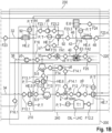
- FIG. 1a , b and c provide an overview, by means of a schematic process flow diagram, of a so-called plastic-to-feedstock plant or plastic-to-oil (in brief: PtO or P2O) plant according to the invention and the related processes during operation of the plant for converting plastics, in particular polyolefin waste, into petrochemical products / feedstock (in particular oil and fuel gas).
- plastic-to-feedstock plant or plastic-to-oil in brief: PtO or P2O
- petrochemical products / feedstock in particular oil and fuel gas
- 100-110-120-130 are the reactions' section; 200 is the section where the pyrolysis products are cooled down, fractionated and stored; 220 is the section where the fuel gas as separated from liquid fraction is sent to energy recovery; 230 is the flue gas and off gas cooling section with heat recovery; 300 is the water circuit; 310 is the scrubbing section of flue gas and off gas.
- An input flow F1 of plastic waste at ambient temperature here a polyolefin mixture, previously sorted, cleaned, shredded and dried, and preferably having a maximum amount of moisture of 10% and preferably a maximum fraction of chlorine of 1%, enters the plant in a commercially available feeding and pre-conditioning equipment E.1.
- the feeding and pre-conditioning equipment E.1 is preferably able to promote densification, heating, degassing (in particular with respect to moisture and hydrochloric acid, if chlorine is present) and complete melting of the plastics.
- the off-gas flow F3 of this pre-conditioning process typically at 300°C, is sent to cleaning in a scrubbing unit E.4 via off-gas line 2 before being sent to further cleaning stages and ultimately being vented into the environment.
- the melt flow F2 which preferably is a low viscous liquid flow at preferably 400°C, is sent via plastic melt flow feed line 4, also called input feed line, to a cracking reactor V.1 described in detail further below, entering the reactor vessel at plastic melt flow inlet port 5.
- the fed plastic melt is undergoing a thermo-chemical cracking or pyrolysis process, preferably at a process temperature in the range of 450-500°C.
- the main output flow, i.e. pyrolysis products output flow F4 from the cracking reactor V.1 is constituted by pyrolysis products that exit at said temperature of preferably 450-500°C (depending of the set-up value for reactor operation) via pyrolysis products outlet port 6 and the subsequent pyrolysis products output line 7.
- the flow F4 is sent to a heat exchanger 1 (also labelled HE.1) that removes heat by decreasing the temperature from said value to preferably 260°C.
- the heat exchanger 1 can be regarded as a partial condenser.
- the heat removed from the flow F4 is transferred to a flow of cooling medium, preferably cooling water.
- the cooling medium enters the heat exchanger 1 at cooling medium supply line 10 at preferably 15°C and leaves via cooling medium discharge line 12 at preferably 80°C.
- the corresponding cooling medium supply and re-cooling devices / systems are indicated in the FIG. 1c (section 300) but need not be described here in detail.
- the flow of cooled-down pyrolysis products leaving the heat exchanger 1 is led via connecting line 14 into a gas-liquid separator 16 (also labelled S.1), wherein the liquid constituents are separated from the gaseous constituents.
- the gaseous pyrolysis products flow F10 is drawn via pyrolysis gas exhaust line 18 to further treatment described below.
- the liquid pyrolysis products flow F6, also called recycled heavy products flow, emerging from the separator 16 is recirculated in the cracking reactor V.1 via pyrolysis products recirculation line 20 at preferably 260°C and enters the reactor vessel at recycled pyrolysis products inlet port 21 to undergo a further cracking and reduce the molecular weight in the desired range. This partial condensation with recycling to the reactor can be avoided if the heavy fraction is small.
- Another flow namely (recycled) particles flow F7 or alternatively recycle flow, composed by particles pre-heated in another reactor, namely combustion reactor or briefly combustor V.2, enters the cracking reactor V.1 via (recycled) particles feed line 22 and (recycled) particles inlet port 23, for example at 750°C, thereby adding the sensible heat necessary to reach the desired temperature for pyrolysis reaction by means of a direct heat exchange of the mixing flows inside the reactor vessel.
- the particles in particular quartz and/or silica sand and/or ceramic coated spherule etc., are continuously cycled between the cracking reactor V.1 and the combustor V.2. to support the pyrolysis process in the cracking reactor V.1 as described in detail below.
- the particles do not directly participate in the chemical pyrolysis reactions or only do so to a small extend and are therefore regarded as catalytic and/or inert particles.
- the particles are extracted from the bottom of the cracking reactor V.1 together with the carbonaceous solid fraction (briefly: coke or char) produced by polymers cracking (a.k.a. pyrolysis) via char and particles outlet port 24 and char and particles output line 25, at a temperature corresponding to the temperature inside the cracking reactor V.1, preferably at 450°C.
- the char and particle flow F5 is addressed and fed at controlled rate by means of a transport and metering system E.2 into the combustor V.2 via char and particle inlet port 26 at said temperature.
- the char and particles output line 25, in this context also called metering line, is kept under a slight negative pressure in order to avoid oxygen inlet (backflow from combustor V.2) in the reactor V.1. This is achieved by a suction pump p3, which on the inlet side is fluidically connected via suction buffer E.5 to the transport and metering system E.2 and on the outlet side discharges into the combustor V.2.
- Air is in fact fed in the combustor V.2 as combustion air flow FA2 via combustion air supply line 27 and combustion air inlet port 28 in order to promote combustion of carbonaceous material coming from the reactor V.1.
- air drawn from the environment by air pump / blower p7 air flow FA1 is preferably pre-heated (in section 230) to reach preferably 250°C as described further below.
- air flow FA1 air drawn from the environment by air pump / blower p7
- air flow FA1 air flow FA1
- air flow FA1 air flow FA1
- the complete combustion of carbon and residues mixed with the particles extracted by the cracking reactor V.1 is guaranteed by using an excess of oxygen and a suitable residence time.
- the combustor V.2 is preferably an entrained reactor, where the superficial gas velocity is much greater than the particles terminal velocity (see detailed description below). In this way the particles are cleaned from residues stuck over them, that is residues agglomerated in the preceding pyrolysis process in the cracking reactor V.1.
- the particles are heated due to exothermic reaction and then transported out of the combustor V.2 with flue gas along the reactor riser and via combustion products and particles outlet port 29 and combustion products and particles output line 30 (as combustion products output flow F19, for example at 750°C) to a flu-id/particles separator 90 which preferably is cyclone separator S.2.
- the particles are separated from the combustion flue gas.
- the hot particles flow also called (recycled) particles flow F7 or recycle flow is introduced to the cracking reactor V.1 at preferably 750°C via (recycled) particles feed line 22 and (recycled) particles inlet port 23, as already described above.
- the particles buffer S.3 within the particles feed line 22 between cyclone separator S.2 and cracking reactor V.1 is maintained at very slight negative pressure with the help of suction pump p2 to guarantee the absence of flue gas in the recycled particles flow F7 introduced to the cracking reactor V.1. Therefore, suction pump p2 is fluidically connected to the buffer S.3 on the inlet side and to the flue gas line 32 (see next paragraphs) on the outlet side.
- the cracking reactor V.1 and the combustor V.2 are part of a particles loop 94 which contains a multitude of solid particles, such that during operation the particles are cycled from the cracking reactor V.1 to the combustor V.2 and back.
- the flue gas flow F22 from the cyclone separator S.2 and the purge gas flow F21 from the buffer S.3 are mixed at line junction 31 (three-way valve) and sent as flue gas flow F23 at preferably 750°C via flue gas line section 32 to heat exchanger HE.2 (preferably a dry cooler) and to heat exchanger HE.3 that transfers part of the heat to the combustion air flow FA1/FA2.
- the flue gas flow F23.3 then is sent to another heat exchanger HE.4 (cooler) in order to decrease the flue gas temperature below 100°C. At this temperature the flue gas flow F23.4 can be addressed to the scrubbing unit E.4.
- the whole heat exchanger line can be adapted to specific cases in order to optimize the heat recovery.
- the heat flow can be used, for instance, to feed the air dryers of plastic scraps in the sorting line.
- the gaseous pyrolysis products flow F10 / F10.1 coming from separator 16 enters via fractionation gas input line 34 and by using pump p4 in the partial condenser S.5, coupled to the heat exchanger HE.5, thereby producing the flow F11 of condensed pyrolysis products or "syncrude” (synthetic crude oil) at a temperature below 260°C (section 210). After a final cooling process within heat exchanger HE.7 these products are stored in the oil tank T.1 for further delivery and usage.
- the vapor phase leaving the partial condenser S.5 is sent to a second condenser S.6, coupled to heat exchanger HE.6, to complete the condensation and the consequent separation between the non-condensable gas (flow F15) and the liquid phase (flow F14).
- This latter flow F14 is delivered by means of p8 pump into the mixing valve v6 where it is mixed with the "heavy" flow F11.
- the flow F14 is at 25°C while the flow F11 is at higher temperature (preferably 260°C); the flow F12 resulting from their mixing has to be cooled down via heat exchanger HE.7 at 50°C or lower value before to be stored in the oil tank T.1.
- the described condensation process within condensers S.5 and S.6 of the fractionation section 210 has two aims: a) separate the non-condensable gases to be addressed to the engine (see below) without oil drops inside; b) separate the heaviest fraction (T>260°C) in case of start-up period, not steady-state regimes, etc., by avoiding to mix this fraction with the light flow.
- the valve v6 interrupts the connection with flow F11 that is accumulated in the condenser S.5 or deviated (not shown in the figure) in an off-specification tank.
- a distillation column can be installed in place of this process by reaching an effective fractionation into more flows (NCG, jet fuel, gasoline, kerosene, off-spec.).
- NCG jet fuel
- gasoline kerosene
- off-spec. off-spec.
- the non-condensable gas flow F15 is sent via non-condensable gas line 35 to a controlled three-way valve v8 that divides the flow F15 into two flows: firstly, the recycled fuel gas return flow F16, which can be zero, is sent to the combustor V.2 via recycled fuel gas return line 38 and recycled fuel gas inlet port 39 (see FIG. 1a ) at preferably 25°C in order to provide additional fuel for the combustion and to guarantee that the set-up operating temperature of the combustor V.2 and therefore the desired temperature of the hot particles flow F7 is reached.
- the recycled fuel gas return flow F16 which can be zero
- the larger part of the flow F15 is sent as recycled fuel gas flow F17 via recycled fuel gas line 40 to a combustion engine E.3 where an air flow, preferably a partial stream of the pre-heated air flow FA2, is also fed to produce flue gas and electric energy.
- the amount of electricity produced is variable but about 0,4 kWh/kg of polyolefins feed F2 are produced by the engine E.3 fed by fuel gas.
- the flue gas is sent via flue gas line 42 to flue gas treatment equipment and leaves the plant through a stack E.6.
- the pre-heating temperature for the flow FA2 has been set at preferably 250°C.
- the flue gas flow F23.3 at preferably 510°C is led via flue gas line section 46 to a dry cooler HE.4 or a cooling tower, depending on the size of the plant and possible use of the heat.
- a flue gas pump p6 or blower is switched into flue gas line section 44 between heat exchangers HE.2 and HE.3 in order to support the flue gas flow.
- Alternate or additional flue gas pumps may be switched into other sections, for example 32, 46, 48, of the flue gas line.
- the entirety of flue gas line sections, in particular 32, 44, 46, 48, constitutes a flues gas line 92.
- the overall plant is completed by state-of-the-art auxiliaries shown in the section 300 of FIG. 1c such as fresh water supply, cooling water supply, reservoirs for the distillation products, according lines, valves and pumps. However, they are not integral to the working of the invention and thus need not be described here in detail.
- the cracking reactor V.1 used in the plant according to FIG. 1a is preferably a two-zone reactor where a continuous stirred tank reactor (CSTR) behavior is ensured in the mid zone while a laminar flow (PFR) behavior is reached in the top zone with essentially two kind of input streams: the main type is dedicated to the plastic input flow F1, preferably in molten state as flow F2, and preferably, but not necessarily, supplemented by the recycled liquid (heavy) pyrolysis products flow F6, pushed by a pump if necessary, while the other is constituted by preferably inert particles (quartz or silica sand, ceramic coated spherule, etc.) preferably having a mean diameter ranged between 50 micron and few millimeters and a high hardness and heat capacity.
- CSTR continuous stirred tank reactor
- PFR laminar flow
- This (recycled) particles' flow F7 is previously heated in another reactor, namely the combustor V.2 where a desired enthalpy is transferred to a given mass flow of sand particles (see next section for details).
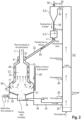
- the basic topology of input and output flows with respect to the cracking reactor V.1 is also visualized in FIG. 2 , describing the spatial structure of an advantageous embodiment and the main flow patterns of particles and pyrolysis products in the reactor V.1 occurring therein during operation.
- FIG. 2 shows also the peculiar connection between the cracking reactor V.1 and the combustor V.2.
- the combustor V.2 is fed by the main flow F5/F8 made by char and particles and by the flow F16 of recycled fuel gas, if needed, and by the flow FA2 of pre-heated air. This latter has the crucial role to provide the transportation of particles along the combustor V.2 riser so guaranteeing a transport regime.
- the gas velocity depends by the properties of particles; in the example the flue gas velocity is about 5m/s.
- the combustion products and particles outlet port 29 of the combustor V.2 is located higher than the particles inlet 23 port into the cracking reactor V.1, and hence the backflow of particles into the cracking reactor V.1 is supported by gravity.
- the sensible heat contained in the particles' flow F7 leads the temperature inside the cracking reactor V.1 to the desired range around preferably 480°C.
- the heat exchange rate between the intermixing input streams inside the cracking reactor V.1 is really fast due to the multitude of particles (e.g. > 400 million for 350-micron sand particles) that merge with the plastic flow and to the peculiar design of the reactor which will now be described in more detail.
- the mass ratio between the mass flow of particles and the polymer flow is about 3, but it can be changed with different particles or polymer.
- the FIG. 2 shows the loop 94 of the particles and the route of transportation for the char/coke residue from the bottom of reactor V.1 throughout the port 24, to the transportation screw line 25, to the bottom of combustor V.2.
- the air flow FA2 introduced throughout the port(s) 28 transports the particles and burns the char/coke along the column.
- a cyclone separator S.2, or other equivalent device separates the combustion products and particles output flow F19 into the particles flow F7 and the flue gas flow F22.
- FIG. 3 shows a longitudinal sketch of an advantageous cracking reactor V.1 of the plastic-to-oil plant according to FIG. 1 and FIG. 2 , wherein the density of material inside is indicated by shades.
- the dark shade is related to a high density of particles with a limited voidage.
- the cracking reactor V.1 comprises an upright reactor vessel 60 which in turn comprises, from top to bottom,
- the interior space within section III essentially is divided into two subspaces by an internal partition wall 64: firstly, the inner space 74 surrounded / enclosed by the partition wall 64, and secondly the interspace 72 between the partition wall 64 and the reactor vessel wall 70.
- the partition wall 64 provides a material barrier but is preferably well heat-conductive. More precisely, the partition wall 64 comprises an essentially cylindrical partition wall section 66 in coaxial arrangement with the cylindrical main body of the reactor vessel 60 and an essentially spherical or calotte-type partition wall cap 68 which follows the contour of the cap 62 of the reactor vessel 60.
- the interspace 72 between the partition wall 64 and the reactor vessel wall 70 comprises a ring-like / annular circumferential part (downcomer channel 80) and a curved top part, in total defining an interconnected (upside down) U-like interspace 72 or channel around the inner space 74 in the sectional view of FIG. 2 .
- the interspace 72 opens, after an enlargement, into the interior of the reactor vessel 60 via lower openings 76.
- the distance of the partition wall 64 to the reactor vessel wall 70 is chosen such that the width of the interspace 72 is small in comparison to the total diameter of the reactor vessel 60. In other words, the interspace 72 defines a narrow circumferential channel in comparison to the relatively wide inner space 74.
- the circumferential baffles 77 which within section II protrude from the reactor vessel wall 70 into the interior of the reactor vessel 60 can have different angles of inclination and length. They allow to transform the vertical velocity vector of particles flow discharging via openings 76 into a tangential vector, thereby allowing or supporting mixing inside the reactor vessel 60.
- the baffles 77 allow to affect the residence time of particles and polymers injected from adjacent openings / nozzles, thereby avoiding that both go down in the bottom vessel without a proper reaction time.
- the partition wall 64 preferably comprises a number of higher (in comparison to lower openings 76) holes or openings 78, preferably evenly distributed over the vertical (cylinder barrel-like) area, thereby defining small flow passages from the interspace 72 to the inner space 74, bypassing the circumferential downcomer channel 80.
- the openings 76 can be present or not.
- interspace 72 between an external and an internal wall (double-wall).
- the interspace 72 provides a flow channel for the incoming hot particles flow F7 which is in heat exchange relation to product flow within the inner space 74 of the reactor vessel 60 and which has as well-defined outlet geometry in order to promote mixing of the different flows.
- the plastics/polymer flow is sent by a tube of the feed line 4 under a pressure preferably larger than 50 bar into a preferably circumferential volume or chamber 82, which is located at section I around the cylindrical char and particles outlet and which is connected via a number of distributing openings or through holes (distributors), in particular nozzles 84, in the vessel wall of the cone-like transition zone to section II.
- the distributors or nozzles 84 are preferably evenly or uniformly distributed over the circumference of the annular cone area, and they are preferably located below the baffles 77.
- the pressure difference between chamber 82 and vessel 60 creates high velocity streams of plastics/polymer flow inside the section II of the reactor.
- the preferably annular chamber 82 or plenum functions as a distribution ring, distributing the incoming plastic melt flow to the distributors or nozzles 84.
- the pressure of preferably more than 50 bar in the annular chamber 82 or plenum is reached thanks to the driving force realized by the feeding and pre-conditioning equipment E.1, which preferably comprises an extruder, and is correlated to the shape and size of the nozzles 84 (see FIG. 3 and FIG. 4 ).
- the value depends on the nozzles' 84 pressure drop.
- a given number of nozzles 84 having a given size and shape allows to create a pressure drop over 50 bar, so promoting a pressurized flow into the reactor vessel 60, such that the injected molten polymer is in a liquid-like state (above a corresponding density threshold value).
- feed line 4 which carries the input plastic melt flow F2 flow after pre-conditioning of the input flow F1 of plastic waste in the feeding and pre-conditioning equipment E.1 discharges into the reactor vessel 60 via plastic melt flow inlet port 5 and nozzles 84 roughly at section II.
- Pyrolysis products recirculation line 20 which carries the recycled liquid (heavy) pyrolysis products flow F6 preferably discharges into the reactor vessel 60 throughout the recirculation line 20 and inlet port 21 which is preferably located above the baffles 77 in section II. Alternatively, there may be a separate discharge opening into the reactor vessel 60, preferably at the height of section I.
- the recirculation line 20 can be also absent if heavy fraction is produced in small amount or not produced at all.
- Recycled particles feed line 22 which carries the recycled particles flow F7 of cleaned and heated particles coming from the combustor V.2 discharges into the top region of the vessel, preferably at the center of the top cover 62.
- the flow of hot particles is therefore injected into the interspace 72 and possibly split into two parts: firstly, a downflow in the annular downcomer channel 80 which enters the interior of the reactor vessel 60 at the lower end of the partition wall 64 through lower openings 76, and secondly a spray-like flow through the lateral openings 78 in the top zone of the partition wall 64, thereby bypassing the circumferential downcomer channel 80.
- Pyrolysis products output line 7 which carries the output flow F4 of pyrolysis products from the cracking reactor V.1 is preferably connected to the upper part of section III of the reactor vessel 60 through pyrolysis products outlet port 6.
- the line connection reaches through the interspace 72.
- the pyrolysis products outlet port 6 or opening into the output line 7 is located within the partition wall cap 62 such that the output flow F4 through said line does not interfere with the hot particles input flow in the circumferential downcomer channel 80.
- the arrangement is preferably such that the pyrolysis outflow does not interfere with the particles inflow through openings 78.
- the flow F5 is addressed to a buffer vessel 85, kept under depression and possibly under nitrogen flow via nitrogen inlet 88, to form a static head 86.
- the feeder 87 which is part of the transport and metering system E.2 indicated in FIG. 1 , extracts the char & particles flow, addressing it to the combustor V.2.
- the static pressure and inertization by using nitrogen allow to avoid (back-) flow of oxidant gas from combustor V.2 to pyrolizer / cracking reactor V.1.
- a safety valve v3 to provide an immediate pipe closing is also located here ( FIG. 1a ).
- a venting line 89 attached to buffer vessel allows for addressing the pyrolysis gas into the combustor by means a dedicated pump in order to avoid overpressure in the feeder and undesired combustion in a limited volume of the feeder at the combustor inlet, where oxygen diffusion is possible.
- the reactor design specified above is optimized to promote uniform heating by avoiding hot areas / spots and to promote a perfect mixing.
- the interspace 72 is where the hot inter particles flow promotes an indirect heating in the top zone of the inner space 74.
- the hot particles in the downcomer channel 80 reach the mid zone of the reactor vessel 60 via lower openings 76, they enter in the interior of the reactor by mixing with the feed rate of polymers, and then the reaction occurs with high efficiency.
- the purpose a of possible flow of particles through holes 78 to the interior of the top zone of the reactor vessel 60 is to balance the heat loss in the top zone due to completion of reactions (endothermic reactions). The lowering of temperature is avoided in order to keep the kinetic rate at high level. Nevertheless, the openings 78 are not necessary in all cases and can be totally avoided.
- U g is the superficial gas velocity
- U mf is the minimum fluidization velocity function of particles properties and reactor temperature
- W reacting_matter is the pyrolysis products mass rate
- S mid zone is the transversal section of reactor as calculated by taking into account the voidage of the bed, function of the internal diameter of reactor, related to section II.
- the mixing in the reactor is then promoted by the flow of hot particles fed at different levels of the reactor vessel 60 as explained above.
- the particles accumulate together with heavier products produced by the chemical reactions including the carbonaceous by-products (char).
- a transport and metering system (feeder) E.2 transports the particles and the carbon stuck on them to an entrained combustor V.2 where the carbon, plastic residues and tars are burned, therefore the particles are cleaned and also heated at the combustor temperature, that is preferably between 750 and 1000°C.
- the subsequent cyclone separator S.2 is preferably mounted at the top of combustor V.2 and is preferably equipped with a rotary valve v1 on the downstream side which distributes in a controlled manner the regenerated and heated particles in the cracking reactor V.1.
- This loop can be infinitely reproduced, thereby avoiding expensive methods to produce and provide heating as well to use mechanical parts inside the reactors for mixing, to sustain cost for disposal of carbon and residues.
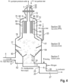
- FIG. 4 A variation of the embodiment according to FIG. 3 is shown in FIG. 4 .
- a number of vertical standpipes 95 is arranged within Section III of the reactor vessel 60.
- the respective standpipe 95 is fluidically connected to the upper region of the interspace 72. That is, the standpipe 95 comprises an inlet opening 96 which is arranged in the partition wall cap 68.
- the respective standpipe 95 comprises an outlet opening 97, blowing into the interior of the reactor vessel 60.
- the respective outlet opening 97 is arranged in a lower region of Section III, just above the transition into Section II.
- the cracking reactor V.1 described above with reference to FIG. 3 and FIG. 4 can be virtually divided into three zones:
- a reduced diameter of this latter section is used.
- a part of flow F7 of hot particles should be addressed here via openings 78 in order to balance the temperature drop, or a series of vertical standpipes should be added to create a larger exchange surface.
- the mid zone is where cracking occurs while the top zone is where the secondary and tertiary reactions, including cyclization and isomerization, are completed together with waxes cracking.
- the densities of mixture in the mid zone and in the top have different values by changing from 500 kg/m 3 to 2 kg/m 3 .
- the reaction process is then controlled by the kinetic rate of chemical conversion.
- the reactor volume is then obtained by using the kinetic equation.
- the first order kinetics allows to obtain the residence time (t R ) by fixing the conversion degree (x R ), the reactor temperature (T R ) and the kinetic parameters (E, k 0 ).
- the required volume of reactor necessary to convert polyolefins into oil with the invention is few liters for each polymer feed rate (e.g. from 3 to 6 liters/(kg/h) for given feeding and reactor temperature), much smaller than other technologies where the massive recycling of pyrolysis products to the reactor, used to promote mixing and heat exchange, requires a very large volume.
- the according arrow inside the reactors represents: the endothermic reactions heat (arrow from internal to external), that is the heat to be provided to the system by external sources; and the exothermic reactions heat (arrow from external to internal), that is the heat generated by the system.
- the energy balance is provided in order to show that the chemical energy of carbon discharged from the bottom of the cracking reactor V.1, once it is converted into sensible energy in the combustor V.2, is sufficient to guarantee that the reactor reaches the desired reaction temperature.
- the char/coke fraction is lower than expected by kinetic model, a part of fuel gas, accordingly with the FIG. 1b is addressed to the combustor to provide the necessary chemical energy.
- Preferred main characteristics of the the plant according to the invention can be summarized in tabular form as follows: Physical state of plastic feeding Low viscous liquid Reactor type Continuous Hydrodynamics regime Turbulent (for more than 80% of reaction time) Heating method Direct internal (exchange with hot particles) Heating rate Very fast Waste (as fraction feeding) 0%
Landscapes
- Chemical & Material Sciences (AREA)
- Oil, Petroleum & Natural Gas (AREA)
- Engineering & Computer Science (AREA)
- Chemical Kinetics & Catalysis (AREA)
- General Chemical & Material Sciences (AREA)
- Organic Chemistry (AREA)
- Life Sciences & Earth Sciences (AREA)
- Wood Science & Technology (AREA)
- Analytical Chemistry (AREA)
- Physics & Mathematics (AREA)
- Thermal Sciences (AREA)
- Production Of Liquid Hydrocarbon Mixture For Refining Petroleum (AREA)
- Separation, Recovery Or Treatment Of Waste Materials Containing Plastics (AREA)
Claims (10)
- Anlage zum Umwandeln von Kunststoffen in petrochemische Produkte, umfassend einen Crack-Reaktor (V.1) für eine Pyrolysereaktion oder einen thermochemischen Prozess, wobei die Kunststoffe zumindest in vergaste Pyrolyseprodukte und Kohle umgewandelt werden, und ferner umfassend eine separate Verbrennungsvorrichtung (V.2),wobei der Crack-Reaktor (V.1) einen Reaktorbehälter (60) mit einem unteren Abschnitt (Abschnitt I), einem mittleren Abschnitt (Abschnitt II) und einem oberen Abschnitt (Abschnitt III) umfasst, wobei der Reaktorbehälter (60) ferner eine Einlassöffnung für Kunststoff, eine Einlassöffnung (23) für Partikel, eine Auslassöffnung (6) für Pyrolyseprodukte, die aus dem oberen Abschnitt (Abschnitt III) ablässt, und eine Auslassöffnung (24) für Kohle und Partikel, die aus dem unteren Abschnitt (Abschnitt I) ablässt,wobei die Verbrennungsvorrichtung (V.2) eine Einlassöffnung (26) für Kohle und Partikel, eine Einlassöffnung (28) für Verbrennungsluft und eine Auslassöffnung (29) für Verbrennungsprodukte und Partikel umfasst,wobei die Auslassöffnung (24) für Kohle und Partikel des Crack-Reaktors (V.1) mit der Einlassöffnung (26) für Kohle und Partikel der Verbrennungsvorrichtung (V.2) verbunden ist und die Auslassöffnung (29) für Verbrennungsprodukte und Partikel der Verbrennungsvorrichtung (V.2) mit der Einlassöffnung (23) für Partikel des Crack-Reaktors (V.1) verbunden ist,wobei der Crack-Reaktor (V.1) und die Verbrennungsvorrichtung (V.2) deshalb Teil eines Partikelkreislaufs (94) sind, der eine Vielzahl von festen Partikeln enthält, so dass die Partikel während des Betriebs vom Crack-Reaktor (V.1) zur Verbrennungsvorrichtung (V.2) und zurück im Kreislauf transportiert werden,wobei der Crack-Reaktor (V.1) derart ausgelegt ist, dass das Mischen im Crack-Reaktor (V.1) hauptsächlich durch einen Strom der Partikel gefördert wird, der von der Oberseite des Crack-Reaktors (V.1) im Wesentlichen im Gegenstrom mit einem Strom der Pyrolyseprodukte zugeführt wird, ohne dass mechanische Mischvorrichtungen erforderlich sind,dadurch gekennzeichnet, dassdie Einlassöffnung für Kunststoff eine Einlassöffnung (5) für einen Kunststoffschmelzstrom ist, die in den unteren Abschnitt (Abschnitt I) eingebunden ist,wobei die Einlassöffnung (5) für den Kunststoffschmelzstrom einen Kunststoffschmelzstrom in eine ringförmige Kammer (82) einspeist, die in den mittleren Abschnitt (Abschnitt II) des Reaktorbehälters (60) über eine Anzahl von Düsen (84) mündet, die in der Lage sind, eine hochviskose Kunststoffschmelze mit hohem Druck in den Behälterkörper einzuspritzen, wobei der Druck im Bereich von 50 bis 80 bar oder sogar höher liegt,wobei die Einlassöffnung (23) für Partikel in einen Kanal führt, der zumindest teilweise in den mittleren Abschnitt (Abschnitt II) mündet, und wobei der Kanal als Zwischenraum (72) zwischen einer äußeren Reaktorbehälterwand (70) und einer wärmeleitenden inneren Trennwand (64) ausgeführt ist.
- Anlage nach Anspruch 1, wobei ein Fluid-/Partikelabscheider (90), der vorzugsweise einen Zyklonabscheider (S.2) umfasst, in der Verbindung zwischen der Auslassöffnung (29) für Verbrennungsprodukte und Partikel der Verbrennungsvorrichtung (V.2) und der Einlassöffnung (23) für Partikel des Crack-Reaktors (V.1) derart angeordnet ist, dass hauptsächlich Partikel in die Einlassöffnung (23) für Partikel, aber keine fluidischen Verbrennungsprodukte eintreten.
- Anlage nach Anspruch 2, wobei eine Rauchgasleitung (92) fluidische Verbrennungsprodukte vom Fluid-/Partikelabscheider (90) zu einer Rauchgasbehandlungsanlage führt, die eine Reinigungseinheit (E.4) oder eine äquivalente Behandlungsvorrichtung umfasst.
- Anlage nach einem der vorhergehenden Ansprüche, wobei die Auslassöffnung (6) für Pyrolyseprodukte des Crack-Reaktors (V.1) über eine Pyrolysegas-Abgasleitung (18) mit einem Fraktionierungsabschnitt (S.5, S.6) und/oder einer Destillationskolonne verbunden ist.
- Anlage nach Anspruch 4 in Verbindung mit Anspruch 3, wobei ein Wärmeübertragungssystem dazu konfiguriert ist, Wärme von einem Rauchgasstrom (F23) innerhalb der Rauchgasleitung (92) auf einen Strom (F10) aus gasförmigen Pyrolyseprodukten innerhalb der Pyrolysegas-Abgasleitung (18) zu übertragen, die zum Fraktionierungsabschnitt (S.5, S.6) und/oder zur Destillationskolonne führt.
- Anlage nach einem der vorhergehenden Ansprüche, wobei eine Pyrolyseprodukt-Rückführungsleitung (20) mit dem Crack-Reaktor (V.1) derart verbunden ist, dass während des Betriebs kondensierte Pyrolyseprodukte zumindest teilweise in den Crack-Reaktor (V.1) zurückgeführt werden.
- Anlage nach Anspruch 3, wobei ein Wärmetauscher (HE.3) derart in der Rauchgasleitung (92) angeordnet ist, dass der Wärmetauscher (HE.3) Wärme eines Rauchgasstroms (F23) innerhalb der Rauchgasleitung (92) zu einem Verbrennungsluftstrom (FA1, FA2) innerhalb einer Verbrennungsluftzufuhrleitung (27) überträgt, die zur Einlassöffnung (28) für Verbrennungsluft der Verbrennungsvorrichtung (V.2) führt.
- Anlage nach Anspruch 4, wobei eine rückgeführte Rauchgasrücklaufleitung (38) von dem Fraktionierungsabschnitt (S.5, S.6) oder der Destillationskolonne zur Verbrennungsvorrichtung (V.2) führt.
- Anlage nach Anspruch 4 oder 8, wobei eine rückgeführte Rauchgasleitung (40) von dem Fraktionierungsabschnitt (S.5, S.6) oder der Destillationskolonne zu einem Verbrennungsmotor (E.3) führt, der mit einem elektrischen Generator gekoppelt ist.
- Anlage nach einem der vorhergehenden Ansprüche, wobei die Verbrennungsvorrichtung (V.2) ein Flugstrom-Steigrohr umfasst.
Priority Applications (3)
| Application Number | Priority Date | Filing Date | Title |
|---|---|---|---|
| HRP20240214TT HRP20240214T1 (hr) | 2019-04-17 | 2020-04-15 | Postrojenje za preradu plastike u ulje za pretvaranje plastičnog otpada u petrokemijske proizvode |
| RS20240193A RS65185B1 (sr) | 2019-04-17 | 2020-04-15 | Postrojenje za preradu plastike u ulje za pretvaranje plastičnog otpada u petrohemijske proizvode |
| EP22175734.7A EP4083171A1 (de) | 2019-04-17 | 2020-04-15 | Ein crack-reaktor |
Applications Claiming Priority (2)
| Application Number | Priority Date | Filing Date | Title |
|---|---|---|---|
| DE102019110186.7A DE102019110186A1 (de) | 2019-04-17 | 2019-04-17 | Plastik-zu-Öl-Werk, entsprechender Cracking-Reaktor und damit verbundene Verfahren zum Umwandeln von Plastikabfall in petrochemische Produkte |
| PCT/EP2020/060558 WO2020212403A1 (en) | 2019-04-17 | 2020-04-15 | Plastic-to-oil plant, according cracking reactor, and related methods for converting plastic waste into petrochemical products |
Related Child Applications (2)
| Application Number | Title | Priority Date | Filing Date |
|---|---|---|---|
| EP22175734.7A Division EP4083171A1 (de) | 2019-04-17 | 2020-04-15 | Ein crack-reaktor |
| EP22175734.7A Division-Into EP4083171A1 (de) | 2019-04-17 | 2020-04-15 | Ein crack-reaktor |
Publications (3)
| Publication Number | Publication Date |
|---|---|
| EP3894516A1 EP3894516A1 (de) | 2021-10-20 |
| EP3894516C0 EP3894516C0 (de) | 2023-11-29 |
| EP3894516B1 true EP3894516B1 (de) | 2023-11-29 |
Family
ID=70554000
Family Applications (2)
| Application Number | Title | Priority Date | Filing Date |
|---|---|---|---|
| EP22175734.7A Pending EP4083171A1 (de) | 2019-04-17 | 2020-04-15 | Ein crack-reaktor |
| EP20723996.3A Active EP3894516B1 (de) | 2019-04-17 | 2020-04-15 | Vorrichtun zur umwandlung von kunststoffabfällen zu öl |
Family Applications Before (1)
| Application Number | Title | Priority Date | Filing Date |
|---|---|---|---|
| EP22175734.7A Pending EP4083171A1 (de) | 2019-04-17 | 2020-04-15 | Ein crack-reaktor |
Country Status (11)
| Country | Link |
|---|---|
| US (1) | US11939529B2 (de) |
| EP (2) | EP4083171A1 (de) |
| CN (1) | CN113939578B (de) |
| CA (1) | CA3136518A1 (de) |
| DE (1) | DE102019110186A1 (de) |
| ES (1) | ES2972407T3 (de) |
| HR (1) | HRP20240214T1 (de) |
| HU (1) | HUE065982T2 (de) |
| PL (1) | PL3894516T3 (de) |
| RS (1) | RS65185B1 (de) |
| WO (1) | WO2020212403A1 (de) |
Families Citing this family (13)
| Publication number | Priority date | Publication date | Assignee | Title |
|---|---|---|---|---|
| DE102019110186A1 (de) * | 2019-04-17 | 2020-11-12 | Pruvia Gmbh | Plastik-zu-Öl-Werk, entsprechender Cracking-Reaktor und damit verbundene Verfahren zum Umwandeln von Plastikabfall in petrochemische Produkte |
| CN113020215B (zh) * | 2021-03-09 | 2021-12-10 | 中国华能集团清洁能源技术研究院有限公司 | 从风机叶片中提取玻璃纤维和裂解油的系统及其工作方法 |
| US12043801B2 (en) * | 2021-06-30 | 2024-07-23 | E2 Technologies, Llc | Apparatus and processes for pyrolysis of plastic feeds |
| EP4460535A4 (de) * | 2022-01-05 | 2025-12-24 | Western Res Institute | Polymerabfallverarbeitung zur gewinnung von flüssigen produkten |
| US12553669B2 (en) | 2022-03-22 | 2026-02-17 | Lummus Technology Llc | External combustion air preheat |
| CN114950748B (zh) * | 2022-04-18 | 2023-12-26 | 中石化宁波工程有限公司 | 多级高效气固旋风分离器 |
| CN114806646B (zh) * | 2022-04-27 | 2023-03-24 | 新奥科技发展有限公司 | 降低合成气中焦油含量的双床系统及方法 |
| CN114989840B (zh) | 2022-05-26 | 2023-08-11 | 东南大学 | 一种耦合新能源发电的生物质梯级热解储能方法及装置 |
| CN114989846A (zh) * | 2022-06-16 | 2022-09-02 | 上海电气集团股份有限公司 | 一种塑料热裂解系统和方法 |
| JP2025517939A (ja) * | 2022-06-21 | 2025-06-12 | バーゼル・ポリオレフィン・イタリア・ソチエタ・ア・レスポンサビリタ・リミタータ | 廃プラスチック材料の解重合プロセス |
| MX2023005240A (es) * | 2023-05-03 | 2024-12-06 | Jaime Manuel SOBRADO ESCUDERO | Sistema y metodo catalitico para la obtencion de gasolina y diesel a partir de desechos plasticos |
| EP4471108A1 (de) * | 2023-05-31 | 2024-12-04 | Pruvia GmbH | Anlage und verfahren zur umwandlung von geschmolzenen kunststoffen in petrochemische produkte |
| CN119752480B (zh) * | 2024-12-17 | 2025-08-22 | 中国石油大学(华东) | 废塑料与原油混合进料分级气相脱氢裂解制化学品工艺 |
Family Cites Families (21)
| Publication number | Priority date | Publication date | Assignee | Title |
|---|---|---|---|---|
| CA1081466A (en) * | 1976-03-26 | 1980-07-15 | David S. Mitchell | Countercurrent plug-like flow of two solids |
| US4444007A (en) | 1982-03-12 | 1984-04-24 | Chevron Research Company | Method for combined cycle electrical power generation |
| US4443229A (en) * | 1983-01-31 | 1984-04-17 | Chevron Research Company | Gasification process for carbonaceous materials |
| JPH0731845U (ja) * | 1993-11-15 | 1995-06-16 | 株式会社クボタ | 自動残渣取出し装置を備えたプラスチック廃棄物油化装置 |
| JPH08170081A (ja) * | 1994-12-20 | 1996-07-02 | Toshiba Eng & Constr Co Ltd | 廃棄プラスチック材の油化処理装置および油化処理方法 |
| CA2350180C (en) * | 2001-06-12 | 2006-07-04 | Keng H. Chung | Process for reducing sulphur emissions from a fluidized bed coke burner |
| JP4008329B2 (ja) * | 2002-10-03 | 2007-11-14 | 俊廣 阿部 | 廃有機物燃焼処理装置 |
| DE102007051373B4 (de) * | 2007-10-26 | 2010-11-11 | Hii-Gmbh - Industrianlagen - Bau Und Beratung | Verfahren und Vorrichtung zur Gewinnung von Diesel oder Heizöl aus kohlenwasserstoffhaltigen Rückständen |
| PL212812B1 (pl) * | 2009-03-14 | 2012-11-30 | Bl Lab Spolka Z Ograniczona Odpowiedzialnoscia | Uklad do prowadzenia termolizy odpadowych tworzyw sztucznych oraz sposób prowadzenia termolizy w sposób ciagly |
| DE102012100897A1 (de) * | 2011-08-08 | 2013-02-14 | Kunststoff- Und Umwelttechnik Gmbh | Modulierbares Universalverfahren zur Herstellung von Syntheseprodukten |
| TW201348303A (zh) * | 2012-05-18 | 2013-12-01 | mao-jin Guo | 有機廢棄物熱媒熱裂解油化方法及裝置 |
| CN105555921B (zh) * | 2013-09-18 | 2018-05-22 | 国际壳牌研究有限公司 | 向加氢催化反应供应氢的方法和系统 |
| EP3390573A1 (de) * | 2015-12-18 | 2018-10-24 | Solvay Sa | Verfahren zur herstellung von wachsen und flüssigen brennstoffen aus kunststoffabfällen |
| WO2017103021A1 (en) * | 2015-12-18 | 2017-06-22 | Solvay Sa | Process for continuously converting mixed waste plastic into waxes and liquid fuels by cracking |
| NO345506B1 (en) * | 2018-07-06 | 2021-03-15 | Quantafuel As | Production of hydrocarbon fuels from waste plastic |
| PT3627050T (pt) * | 2018-09-20 | 2021-07-15 | Germano Araujo Carreira | Instalação de pirólise |
| EP3947266A4 (de) * | 2019-03-29 | 2023-02-01 | Eastman Chemical Company | Vergasung von verdichteten textilien und festen fossilen brennstoffen |
| WO2020205404A1 (en) * | 2019-03-29 | 2020-10-08 | Eastman Chemical Company | Polymers, articles, and chemicals made from densified textile derived syngas |
| DE102019110186A1 (de) * | 2019-04-17 | 2020-11-12 | Pruvia Gmbh | Plastik-zu-Öl-Werk, entsprechender Cracking-Reaktor und damit verbundene Verfahren zum Umwandeln von Plastikabfall in petrochemische Produkte |
| US20220169931A1 (en) * | 2019-04-26 | 2022-06-02 | Eastman Chemical Company | Gasification of Torrefied Textiles and Fossil Fuels |
| FI4037817T3 (fi) * | 2019-10-04 | 2026-03-02 | Mura Tech Limited | Menetelmä ja laitteisto polymeerien muuntamiseksi tuotteiksi |
-
2019
- 2019-04-17 DE DE102019110186.7A patent/DE102019110186A1/de not_active Ceased
-
2020
- 2020-04-15 US US17/603,441 patent/US11939529B2/en active Active
- 2020-04-15 CN CN202080039588.5A patent/CN113939578B/zh active Active
- 2020-04-15 HU HUE20723996A patent/HUE065982T2/hu unknown
- 2020-04-15 HR HRP20240214TT patent/HRP20240214T1/hr unknown
- 2020-04-15 EP EP22175734.7A patent/EP4083171A1/de active Pending
- 2020-04-15 PL PL20723996.3T patent/PL3894516T3/pl unknown
- 2020-04-15 WO PCT/EP2020/060558 patent/WO2020212403A1/en not_active Ceased
- 2020-04-15 ES ES20723996T patent/ES2972407T3/es active Active
- 2020-04-15 EP EP20723996.3A patent/EP3894516B1/de active Active
- 2020-04-15 CA CA3136518A patent/CA3136518A1/en active Pending
- 2020-04-15 RS RS20240193A patent/RS65185B1/sr unknown
Also Published As
| Publication number | Publication date |
|---|---|
| CA3136518A1 (en) | 2020-10-22 |
| RS65185B1 (sr) | 2024-03-29 |
| PL3894516T3 (pl) | 2024-04-02 |
| US11939529B2 (en) | 2024-03-26 |
| EP3894516C0 (de) | 2023-11-29 |
| ES2972407T3 (es) | 2024-06-12 |
| CN113939578B (zh) | 2023-04-04 |
| DE102019110186A1 (de) | 2020-11-12 |
| WO2020212403A1 (en) | 2020-10-22 |
| US20220204863A1 (en) | 2022-06-30 |
| HRP20240214T1 (hr) | 2024-05-10 |
| EP3894516A1 (de) | 2021-10-20 |
| EP4083171A1 (de) | 2022-11-02 |
| CN113939578A (zh) | 2022-01-14 |
| HUE065982T2 (hu) | 2024-07-28 |
Similar Documents
| Publication | Publication Date | Title |
|---|---|---|
| EP3894516B1 (de) | Vorrichtun zur umwandlung von kunststoffabfällen zu öl | |
| AU2002220288B2 (en) | Process and gas generator for generating fuel gas | |
| US9631153B2 (en) | Adaptable universal method for producing synthetic products | |
| CZ20014156A3 (cs) | Zařízení pro zplyňování uhlíkatého vsázkového materiálu | |
| NL1009745C2 (nl) | Werkwijze en inrichting voor het vormen van synthesegas uit biomassa en reststoffen. | |
| CN107995921A (zh) | 气化系统 | |
| AU2002220288A1 (en) | Process and gas generator for generating fuel gas | |
| US20180237699A1 (en) | Duplex process for rapid thermochemical conversion of carbonaceous raw materials | |
| PL205461B1 (pl) | Sposób przetwarzania surowców węglowodorowych metodą termicznego lub katalitycznego krakingu i układ do przetwarzania surowców węglowodorowych metodą termicznego lub katalitycznego krakingu | |
| KR102068337B1 (ko) | 바이오매스와 합성수지의 혼합 열분해를 위한 바이오 원유 제조 시스템 | |
| CN113195685A (zh) | 处理含碳材料的工艺和用于其的设备 | |
| US20100270209A1 (en) | Process and device for generating middle distillate from hydrocarbonaceous energy sources | |
| EP3083886B1 (de) | Vorrichtung zur pyrolyse von kohlenstoffhaltigem material | |
| EP3918031B1 (de) | System zur veredelung von synthesegas aus abfallstoffen, städtischen festen abfällen oder biomasse | |
| JP2608376B2 (ja) | プラスチック廃棄物の処理装置 | |
| CN106497606A (zh) | 煤直接加氢热解方法 | |
| US20200216768A1 (en) | Highly efficient and compact syngas generation system | |
| EP4202017A1 (de) | Anlage und verfahren zur umwandlung von kunststoffrohstoffen in brennstoff | |
| JPH1095984A (ja) | 廃プラスチックからの油回収方法 | |
| CN115651715B (zh) | 粉煤干馏装置和方法 | |
| EP2719747B1 (de) | Vergasungsverfahren von kohlehaltigen rohstoffen, holzkohle und kohle | |
| KR20050022696A (ko) | 폐플라스틱 유화시스템 | |
| EP4720227A1 (de) | Anlage und verfahren zur umwandlung von geschmolzenen kunststoffen in petrochemische produkte |
Legal Events
| Date | Code | Title | Description |
|---|---|---|---|
| REG | Reference to a national code |
Ref country code: HR Ref legal event code: TUEP Ref document number: P20240214T Country of ref document: HR |
|
| STAA | Information on the status of an ep patent application or granted ep patent |
Free format text: STATUS: UNKNOWN |
|
| STAA | Information on the status of an ep patent application or granted ep patent |
Free format text: STATUS: THE INTERNATIONAL PUBLICATION HAS BEEN MADE |
|
| PUAI | Public reference made under article 153(3) epc to a published international application that has entered the european phase |
Free format text: ORIGINAL CODE: 0009012 |
|
| STAA | Information on the status of an ep patent application or granted ep patent |
Free format text: STATUS: REQUEST FOR EXAMINATION WAS MADE |
|
| 17P | Request for examination filed |
Effective date: 20210716 |
|
| AK | Designated contracting states |
Kind code of ref document: A1 Designated state(s): AL AT BE BG CH CY CZ DE DK EE ES FI FR GB GR HR HU IE IS IT LI LT LU LV MC MK MT NL NO PL PT RO RS SE SI SK SM TR |
|
| STAA | Information on the status of an ep patent application or granted ep patent |
Free format text: STATUS: EXAMINATION IS IN PROGRESS |
|
| 17Q | First examination report despatched |
Effective date: 20220208 |
|
| DAV | Request for validation of the european patent (deleted) | ||
| DAX | Request for extension of the european patent (deleted) | ||
| GRAP | Despatch of communication of intention to grant a patent |
Free format text: ORIGINAL CODE: EPIDOSNIGR1 |
|
| STAA | Information on the status of an ep patent application or granted ep patent |
Free format text: STATUS: GRANT OF PATENT IS INTENDED |
|
| INTG | Intention to grant announced |
Effective date: 20230622 |
|
| GRAS | Grant fee paid |
Free format text: ORIGINAL CODE: EPIDOSNIGR3 |
|
| GRAA | (expected) grant |
Free format text: ORIGINAL CODE: 0009210 |
|
| STAA | Information on the status of an ep patent application or granted ep patent |
Free format text: STATUS: THE PATENT HAS BEEN GRANTED |
|
| AK | Designated contracting states |
Kind code of ref document: B1 Designated state(s): AL AT BE BG CH CY CZ DE DK EE ES FI FR GB GR HR HU IE IS IT LI LT LU LV MC MK MT NL NO PL PT RO RS SE SI SK SM TR |
|
| REG | Reference to a national code |
Ref country code: GB Ref legal event code: FG4D |
|
| REG | Reference to a national code |
Ref country code: CH Ref legal event code: EP |
|
| REG | Reference to a national code |
Ref country code: DE Ref legal event code: R096 Ref document number: 602020021888 Country of ref document: DE |
|
| REG | Reference to a national code |
Ref country code: IE Ref legal event code: FG4D |
|
| U01 | Request for unitary effect filed |
Effective date: 20231228 |
|
| U07 | Unitary effect registered |
Designated state(s): AT BE BG DE DK EE FI FR IT LT LU LV MT NL PT SE SI Effective date: 20240111 |
|
| REG | Reference to a national code |
Ref country code: NO Ref legal event code: T2 Effective date: 20231129 |
|
| REG | Reference to a national code |
Ref country code: SK Ref legal event code: T3 Ref document number: E 43532 Country of ref document: SK |
|
| REG | Reference to a national code |
Ref country code: HR Ref legal event code: ODRP Ref document number: P20240214T Country of ref document: HR Payment date: 20240415 Year of fee payment: 5 |
|
| REG | Reference to a national code |
Ref country code: GR Ref legal event code: EP Ref document number: 20240400493 Country of ref document: GR Effective date: 20240410 |
|
| REG | Reference to a national code |
Ref country code: HR Ref legal event code: T1PR Ref document number: P20240214 Country of ref document: HR |
|
| REG | Reference to a national code |
Ref country code: ES Ref legal event code: FG2A Ref document number: 2972407 Country of ref document: ES Kind code of ref document: T3 Effective date: 20240612 |
|
| REG | Reference to a national code |
Ref country code: HU Ref legal event code: AG4A Ref document number: E065982 Country of ref document: HU |
|
| PG25 | Lapsed in a contracting state [announced via postgrant information from national office to epo] |
Ref country code: SM Free format text: LAPSE BECAUSE OF FAILURE TO SUBMIT A TRANSLATION OF THE DESCRIPTION OR TO PAY THE FEE WITHIN THE PRESCRIBED TIME-LIMIT Effective date: 20231129 |
|
| U21 | Renewal fee for the european patent with unitary effect paid with additional fee |
Year of fee payment: 5 Effective date: 20240630 |
|
| REG | Reference to a national code |
Ref country code: DE Ref legal event code: R097 Ref document number: 602020021888 Country of ref document: DE |
|
| PLBE | No opposition filed within time limit |
Free format text: ORIGINAL CODE: 0009261 |
|
| STAA | Information on the status of an ep patent application or granted ep patent |
Free format text: STATUS: NO OPPOSITION FILED WITHIN TIME LIMIT |
|
| 26N | No opposition filed |
Effective date: 20240830 |
|
| REG | Reference to a national code |
Ref country code: HR Ref legal event code: ODRP Ref document number: P20240214 Country of ref document: HR Payment date: 20250408 Year of fee payment: 6 |
|
| U20 | Renewal fee for the european patent with unitary effect paid |
Year of fee payment: 6 Effective date: 20250430 |
|
| PGFP | Annual fee paid to national office [announced via postgrant information from national office to epo] |
Ref country code: PL Payment date: 20250403 Year of fee payment: 6 |
|
| PGFP | Annual fee paid to national office [announced via postgrant information from national office to epo] |
Ref country code: ES Payment date: 20250519 Year of fee payment: 6 |
|
| PGFP | Annual fee paid to national office [announced via postgrant information from national office to epo] |
Ref country code: IS Payment date: 20250423 Year of fee payment: 6 Ref country code: RS Payment date: 20250403 Year of fee payment: 6 Ref country code: HU Payment date: 20250411 Year of fee payment: 6 Ref country code: NO Payment date: 20250422 Year of fee payment: 6 |
|
| PGFP | Annual fee paid to national office [announced via postgrant information from national office to epo] |
Ref country code: AL Payment date: 20250414 Year of fee payment: 6 |
|
| PGFP | Annual fee paid to national office [announced via postgrant information from national office to epo] |
Ref country code: HR Payment date: 20250408 Year of fee payment: 6 |
|
| PGFP | Annual fee paid to national office [announced via postgrant information from national office to epo] |
Ref country code: GR Payment date: 20250416 Year of fee payment: 6 |
|
| PGFP | Annual fee paid to national office [announced via postgrant information from national office to epo] |
Ref country code: CH Payment date: 20250501 Year of fee payment: 6 |
|
| PGFP | Annual fee paid to national office [announced via postgrant information from national office to epo] |
Ref country code: RO Payment date: 20250407 Year of fee payment: 6 |
|
| PGFP | Annual fee paid to national office [announced via postgrant information from national office to epo] |
Ref country code: TR Payment date: 20250407 Year of fee payment: 6 Ref country code: SK Payment date: 20250408 Year of fee payment: 6 |
|
| PGFP | Annual fee paid to national office [announced via postgrant information from national office to epo] |
Ref country code: CZ Payment date: 20250402 Year of fee payment: 6 |
|
| PGFP | Annual fee paid to national office [announced via postgrant information from national office to epo] |
Ref country code: IE Payment date: 20250428 Year of fee payment: 6 |
|
| PGFP | Annual fee paid to national office [announced via postgrant information from national office to epo] |
Ref country code: MK Payment date: 20250404 Year of fee payment: 6 |
|
| PGFP | Annual fee paid to national office [announced via postgrant information from national office to epo] |
Ref country code: CY Payment date: 20250404 Year of fee payment: 6 |
|
| PGFP | Annual fee paid to national office [announced via postgrant information from national office to epo] |
Ref country code: GB Payment date: 20260324 Year of fee payment: 7 |
|
| PGFP | Annual fee paid to national office [announced via postgrant information from national office to epo] |
Ref country code: MC Payment date: 20260327 Year of fee payment: 7 |