EP3892880A1 - Power transmission device - Google Patents
Power transmission device Download PDFInfo
- Publication number
- EP3892880A1 EP3892880A1 EP19893997.7A EP19893997A EP3892880A1 EP 3892880 A1 EP3892880 A1 EP 3892880A1 EP 19893997 A EP19893997 A EP 19893997A EP 3892880 A1 EP3892880 A1 EP 3892880A1
- Authority
- EP
- European Patent Office
- Prior art keywords
- clutch
- clutch plates
- side clutch
- driven
- power transmission
- Prior art date
- Legal status (The legal status is an assumption and is not a legal conclusion. Google has not performed a legal analysis and makes no representation as to the accuracy of the status listed.)
- Pending
Links
Images










Classifications
-
- F—MECHANICAL ENGINEERING; LIGHTING; HEATING; WEAPONS; BLASTING
- F16—ENGINEERING ELEMENTS AND UNITS; GENERAL MEASURES FOR PRODUCING AND MAINTAINING EFFECTIVE FUNCTIONING OF MACHINES OR INSTALLATIONS; THERMAL INSULATION IN GENERAL
- F16D—COUPLINGS FOR TRANSMITTING ROTATION; CLUTCHES; BRAKES
- F16D13/00—Friction clutches
- F16D13/58—Details
- F16D13/60—Clutching elements
-
- F—MECHANICAL ENGINEERING; LIGHTING; HEATING; WEAPONS; BLASTING
- F16—ENGINEERING ELEMENTS AND UNITS; GENERAL MEASURES FOR PRODUCING AND MAINTAINING EFFECTIVE FUNCTIONING OF MACHINES OR INSTALLATIONS; THERMAL INSULATION IN GENERAL
- F16D—COUPLINGS FOR TRANSMITTING ROTATION; CLUTCHES; BRAKES
- F16D43/00—Automatic clutches
- F16D43/02—Automatic clutches actuated entirely mechanically
- F16D43/04—Automatic clutches actuated entirely mechanically controlled by angular speed
- F16D43/06—Automatic clutches actuated entirely mechanically controlled by angular speed with centrifugal masses actuating axially a movable pressure ring or the like
- F16D43/08—Automatic clutches actuated entirely mechanically controlled by angular speed with centrifugal masses actuating axially a movable pressure ring or the like the pressure ring actuating friction plates, cones or similar axially-movable friction surfaces
- F16D43/12—Automatic clutches actuated entirely mechanically controlled by angular speed with centrifugal masses actuating axially a movable pressure ring or the like the pressure ring actuating friction plates, cones or similar axially-movable friction surfaces the centrifugal masses acting on, or forming a part of, an actuating mechanism by which the pressure ring can also be actuated independently of the masses
-
- F—MECHANICAL ENGINEERING; LIGHTING; HEATING; WEAPONS; BLASTING
- F16—ENGINEERING ELEMENTS AND UNITS; GENERAL MEASURES FOR PRODUCING AND MAINTAINING EFFECTIVE FUNCTIONING OF MACHINES OR INSTALLATIONS; THERMAL INSULATION IN GENERAL
- F16D—COUPLINGS FOR TRANSMITTING ROTATION; CLUTCHES; BRAKES
- F16D13/00—Friction clutches
- F16D13/22—Friction clutches with axially-movable clutching members
- F16D13/38—Friction clutches with axially-movable clutching members with flat clutching surfaces, e.g. discs
- F16D13/52—Clutches with multiple lamellae ; Clutches in which three or more axially moveable members are fixed alternately to the shafts to be coupled and are pressed from one side towards an axially-located member
- F16D13/54—Clutches with multiple lamellae ; Clutches in which three or more axially moveable members are fixed alternately to the shafts to be coupled and are pressed from one side towards an axially-located member with means for increasing the effective force between the actuating sleeve or equivalent member and the pressure member
- F16D13/56—Clutches with multiple lamellae ; Clutches in which three or more axially moveable members are fixed alternately to the shafts to be coupled and are pressed from one side towards an axially-located member with means for increasing the effective force between the actuating sleeve or equivalent member and the pressure member in which the clutching pressure is produced by springs only
-
- B—PERFORMING OPERATIONS; TRANSPORTING
- B60—VEHICLES IN GENERAL
- B60K—ARRANGEMENT OR MOUNTING OF PROPULSION UNITS OR OF TRANSMISSIONS IN VEHICLES; ARRANGEMENT OR MOUNTING OF PLURAL DIVERSE PRIME-MOVERS IN VEHICLES; AUXILIARY DRIVES FOR VEHICLES; INSTRUMENTATION OR DASHBOARDS FOR VEHICLES; ARRANGEMENTS IN CONNECTION WITH COOLING, AIR INTAKE, GAS EXHAUST OR FUEL SUPPLY OF PROPULSION UNITS IN VEHICLES
- B60K17/00—Arrangement or mounting of transmissions in vehicles
- B60K17/02—Arrangement or mounting of transmissions in vehicles characterised by arrangement, location, or kind of clutch
-
- F—MECHANICAL ENGINEERING; LIGHTING; HEATING; WEAPONS; BLASTING
- F16—ENGINEERING ELEMENTS AND UNITS; GENERAL MEASURES FOR PRODUCING AND MAINTAINING EFFECTIVE FUNCTIONING OF MACHINES OR INSTALLATIONS; THERMAL INSULATION IN GENERAL
- F16D—COUPLINGS FOR TRANSMITTING ROTATION; CLUTCHES; BRAKES
- F16D13/00—Friction clutches
- F16D13/22—Friction clutches with axially-movable clutching members
- F16D13/38—Friction clutches with axially-movable clutching members with flat clutching surfaces, e.g. discs
- F16D13/52—Clutches with multiple lamellae ; Clutches in which three or more axially moveable members are fixed alternately to the shafts to be coupled and are pressed from one side towards an axially-located member
-
- F—MECHANICAL ENGINEERING; LIGHTING; HEATING; WEAPONS; BLASTING
- F16—ENGINEERING ELEMENTS AND UNITS; GENERAL MEASURES FOR PRODUCING AND MAINTAINING EFFECTIVE FUNCTIONING OF MACHINES OR INSTALLATIONS; THERMAL INSULATION IN GENERAL
- F16D—COUPLINGS FOR TRANSMITTING ROTATION; CLUTCHES; BRAKES
- F16D13/00—Friction clutches
- F16D13/58—Details
-
- F—MECHANICAL ENGINEERING; LIGHTING; HEATING; WEAPONS; BLASTING
- F16—ENGINEERING ELEMENTS AND UNITS; GENERAL MEASURES FOR PRODUCING AND MAINTAINING EFFECTIVE FUNCTIONING OF MACHINES OR INSTALLATIONS; THERMAL INSULATION IN GENERAL
- F16D—COUPLINGS FOR TRANSMITTING ROTATION; CLUTCHES; BRAKES
- F16D43/00—Automatic clutches
- F16D43/02—Automatic clutches actuated entirely mechanically
- F16D43/20—Automatic clutches actuated entirely mechanically controlled by torque, e.g. overload-release clutches, slip-clutches with means by which torque varies the clutching pressure
- F16D43/202—Automatic clutches actuated entirely mechanically controlled by torque, e.g. overload-release clutches, slip-clutches with means by which torque varies the clutching pressure of the ratchet type
- F16D43/204—Automatic clutches actuated entirely mechanically controlled by torque, e.g. overload-release clutches, slip-clutches with means by which torque varies the clutching pressure of the ratchet type with intermediate balls or rollers
- F16D43/206—Automatic clutches actuated entirely mechanically controlled by torque, e.g. overload-release clutches, slip-clutches with means by which torque varies the clutching pressure of the ratchet type with intermediate balls or rollers moving axially between engagement and disengagement
-
- F—MECHANICAL ENGINEERING; LIGHTING; HEATING; WEAPONS; BLASTING
- F16—ENGINEERING ELEMENTS AND UNITS; GENERAL MEASURES FOR PRODUCING AND MAINTAINING EFFECTIVE FUNCTIONING OF MACHINES OR INSTALLATIONS; THERMAL INSULATION IN GENERAL
- F16D—COUPLINGS FOR TRANSMITTING ROTATION; CLUTCHES; BRAKES
- F16D67/00—Combinations of couplings and brakes; Combinations of clutches and brakes
- F16D67/02—Clutch-brake combinations
-
- F—MECHANICAL ENGINEERING; LIGHTING; HEATING; WEAPONS; BLASTING
- F16—ENGINEERING ELEMENTS AND UNITS; GENERAL MEASURES FOR PRODUCING AND MAINTAINING EFFECTIVE FUNCTIONING OF MACHINES OR INSTALLATIONS; THERMAL INSULATION IN GENERAL
- F16D—COUPLINGS FOR TRANSMITTING ROTATION; CLUTCHES; BRAKES
- F16D13/00—Friction clutches
- F16D13/22—Friction clutches with axially-movable clutching members
- F16D13/38—Friction clutches with axially-movable clutching members with flat clutching surfaces, e.g. discs
- F16D13/52—Clutches with multiple lamellae ; Clutches in which three or more axially moveable members are fixed alternately to the shafts to be coupled and are pressed from one side towards an axially-located member
- F16D13/54—Clutches with multiple lamellae ; Clutches in which three or more axially moveable members are fixed alternately to the shafts to be coupled and are pressed from one side towards an axially-located member with means for increasing the effective force between the actuating sleeve or equivalent member and the pressure member
- F16D13/56—Clutches with multiple lamellae ; Clutches in which three or more axially moveable members are fixed alternately to the shafts to be coupled and are pressed from one side towards an axially-located member with means for increasing the effective force between the actuating sleeve or equivalent member and the pressure member in which the clutching pressure is produced by springs only
- F16D2013/565—Clutches with multiple lamellae ; Clutches in which three or more axially moveable members are fixed alternately to the shafts to be coupled and are pressed from one side towards an axially-located member with means for increasing the effective force between the actuating sleeve or equivalent member and the pressure member in which the clutching pressure is produced by springs only with means for releasing the clutch pressure in case of back torque
Definitions
- the present invention relates to a power transmission device that can appropriately transmit or stop transmitting rotational power of an input member to an output member.
- a motorcycle has a power transmission device that is used to appropriately transmit or stop transmitting the driving power of an engine to a transmission and a driving wheel.
- the power transmission device includes an input member coupled to the engine side, an output member coupled to the transmission and driving wheel side, a clutch member coupled to an output member, and a pressure member that is capable of moving toward or away from the clutch member.
- the power transmission device is configured to transmit power by moving the pressure member toward the clutch member to press a drive-side clutch plate and a driven-side clutch plate against each other, and is configured to stop transmitting the power by moving the pressure member away from the clutch member to release a press-contact force between the drive-side clutch plate and the driven-side clutch plate.
- a power transmission device including a weight member has been proposed.
- the weight member can press a drive-side clutch plate and a driven-side clutch plate against each other by moving from a radially-inner position to a radially-outer position in a groove portion due to a centrifugal force that is generated as a clutch housing rotates.
- the existing power transmission device because the clutch housing rotates as the engine is driven, it is possible to apply a centrifugal force to the weight member and to transmit the driving power of the engine to a wheel by pressing the drive-side clutch plate and the driven-side clutch plate against each other.
- the existing power transmission device further includes: a release spring that is compressed as an interlocking member moves and the pressure member moves from an inactive position toward an active position and that can apply an urging force while allowing movements of the interlocking member and the pressure member until the drive-side clutch plate and the driven-side clutch plate reach an engaged state before being pressed against each other; and a clutch spring that is compressed in a process in which the interlocking member moves after the drive-side clutch plate and the driven-side clutch plate have reached the engaged state and that can apply a press-contact force between the drive-side clutch plate and the driven-side clutch plate while allowing movement of the interlocking member.
- a release spring that is compressed as an interlocking member moves and the pressure member moves from an inactive position toward an active position and that can apply an urging force while allowing movements of the interlocking member and the pressure member until the drive-side clutch plate and the driven-side clutch plate reach an engaged state before being pressed against each other
- a clutch spring that is compressed in a process in which the interlocking
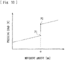
- the existing power transmission device has the following problem. If the difference between a load (maximum load) at the time when compression of the release spring has been finished (see P1 in Fig. 32 ) and a load (set load) at the time when compression of the clutch spring is started (see P2 in the figure) is large, in a process in which the interlocking member moves and the pressure member moves from the inactive position toward the active position as the rotational speed of the engine increases, a dead zone in which the movement of the interlocking member stops (stops while remaining at the movement amount ⁇ in the figure) occurs after compression of the release spring has been finished and before compression of the clutch spring is started.
- the present applicant has examined a power transmission device in which a clutch member is divided into two so that an engine brake can be applied satisfactorily.
- the power transmission device includes a first clutch member that is coupled to an output member, a second clutch member to which a driven-side clutch plate is attached, and a back-torque transmitting cam that can press a drive-side clutch plate and the driven-side clutch plate against each other by moving the second clutch member when a rotational force is input to the first clutch member via the output member.
- the present applicant has eagerly examined effective utilization of a space that is obtained by the arrangement of the first clutch member and the second clutch member.
- the present invention has been made in consideration of such circumstances, and an object thereof is to provide a power transmission device that can suppress feeling of surprise when power is transmitted and can improve operability while efficiently utilizing a space that is obtained by the arrangement of a first clutch member and a second clutch member.
- a power transmission device includes: a clutch housing that rotates together with an input member that is rotated by driving power of an engine of a vehicle and to which a plurality of drive-side clutch plates are attached; a clutch member to which a plurality of driven-side clutch plates that are formed alternately with the drive-side clutch plates of the clutch housing are attached and that is coupled to an output member that is capable of rotating a wheel of the vehicle; a pressure member that is movable between an active position at which the pressure member presses the drive-side clutch plates and the driven-side clutch plates against each other to be able to transmit the driving power of the engine to the wheel and an inactive position at which the pressure member releases a press-contact force between the drive-side clutch plates and the driven-side clutch plates to be able to stop transmitting the driving power of the engine to the wheel; a weight member that is disposed in a groove portion extending in a radial direction of the clutch housing and that is movable from a radially-inner position to
- the clutch member includes a first clutch member that is coupled to the output member, a second clutch member to which the driven-side clutch plates are attached, a back-torque transmitting cam that is capable of pressing the drive-side clutch plates and the driven-side clutch plates against each other by moving the second clutch member when a rotational force is input to the first clutch member via the output member, and a cushioning member that is interposed between the first clutch member and the second clutch member and that is capable of applying an urging force while allowing movements of the interlocking member and the pressure member by being compressed in a process in which the interlocking member moves and the pressure member moves from the inactive position toward the active position.
- the cushioning member is composed of a spring that is set to a load such that the spring is compressed before the clutch spring starts to be compressed.
- the cushioning member is accommodated in an accommodation recessed portion that is formed in a surface at which the first clutch member and the second clutch member face each other.
- the accommodation recessed portion is composed of an annular groove
- the cushioning member is composed of a spring having an annular shape conformed to a shape of the groove.
- the back-torque transmitting cam is formed in a plurality of annular shapes in the surface at which the first clutch member and the second clutch member face each other, and the accommodation recessed portion is formed in a concentric circular shape at a position that is adjacent to the back-torque transmitting cam.
- the power transmission device includes the cushioning member that is interposed between the first clutch member and the second clutch member and that is capable of applying an urging force while allowing movements of the interlocking member and the pressure member by being compressed in a process in which the interlocking member moves and the pressure member moves from the inactive position toward the active position.
- the cushioning member is composed of a spring that is set to a load such that the spring is compressed before the clutch spring starts to be compressed.
- the back-torque transmitting cam it is possible to enable the back-torque transmitting cam to reliably and stably move the second clutch member and to enable the cushioning member to reliably and stably apply an urging force, because the back-torque transmitting cam is formed in a plurality of annular shapes in the surface at which the first clutch member and the second clutch member face each other, and the accommodation recessed portion is formed in a concentric circular shape at a position that is adjacent to the back-torque transmitting cam.
- a power transmission device is a device that is disposed in a vehicle, such as a motorcycle, and is used to appropriately transmit or to stop transmitting the driving power of an engine to a transmission or toward the driving wheel side.
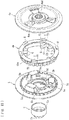
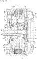
- the power transmission device mainly includes: a clutch housing 2 in which an input gear 1 (input member) that is rotated by the driving power of the engine of the vehicle is formed; a clutch member (a first clutch member 4a and a second clutch member 4b); a pressure member 5 attached on the right side in Fig.
- the clutch member (the first clutch member 4a and the second clutch member 4b); a plurality of drive-side clutch plates 6; a plurality of driven-side clutch plates 7; a weight member 8 that is composed of steel ball members that can move (roll) in the radial direction in the clutch housing 2; an interlocking member 9; and an activation member 10 that can be activated by hand or by an actuator (not shown).
- the symbol S in the figure shows a spring damper
- the symbol B1 shows a roller bearing
- the symbols B2 and B3 respectively show thrust bearings.
- the input gear 1 can rotate around an output shaft 3 when the driving power (rotational force) transmitted from the engine is input.
- the input gear 1 is coupled to the clutch housing 2 via a rivet R and the like.
- the clutch housing 2 includes a housing portion 2a that is composed of a cylindrical member whose right side in Fig. 2 is open and that is coupled to the input gear 1, and a cover portion 2b that is attached so as to close the opening of the housing portion 2a.
- the clutch housing 2 can rotate together with the rotation of the input gear 1 due to the driving power of the engine.
- a plurality of cutouts 2aa are formed in the housing portion 2a of the clutch housing 2 so as to be arranged in the circumferential direction, and the plurality of drive-side clutch plates 6 are attached to be fitted to the cutouts 2aa.
- Each of the drive-side clutch plates 6 is composed of a substantially annular plate material, and is configured to be able to rotate together with the rotation of the clutch housing 2 and to slide in the axial direction (the left-right direction in Fig. 2 ).
- a plurality of groove portions 2ba extending in the radial direction of the cover portion 2b are formed in the bottom surface of the cover portion 2b of the clutch housing 2.
- the weight member 8 is disposed in each of the groove portions 2ba. In a state in which the clutch housing 2 is stopped (an engine stop or idling state) and in a state in which the clutch housing 2 is rotating at a low speed, the weight member 8 is located at a radially-inner position (the position shown in Fig. 2 ). In a state in which the clutch housing 2 is rotating at a high speed, the weight member 8 is located at a radially-outer position.
- the clutch member is coupled to the output shaft 3 (output member) that can rotate the wheel of the vehicle.
- the clutch member is configured by assembling two members, which are the first clutch member 4a and the second clutch member 4b.
- the first clutch member 4a is composed of a disc-shaped member in which a flange surface 4ac is formed along the peripheral edge part thereof.
- the first clutch member 4a is configured so that the output shaft 3 is inserted into an insertion hole 4ad (see Figs. 2 and 6 ) formed at the center thereof, and the first clutch member 4a and the output shaft 3 are coupled to each other in the rotational direction as gears respectively formed therein mesh with each other.
- an inclined surface 4aa that constitutes a press-contact assisting cam and an inclined surface 4ab that constitutes a back-torque limiter cam are formed.
- the second clutch member 4b is composed of an annular member, and is configured so that the driven-side clutch plates 7 are attached by spline fitting to a spline-fitting portion 4ba (see Figs. 2 and 7 ) formed in an outer peripheral surface thereof.
- the pressure member 5 is assembled with the clutch member (the first clutch member 4a and the second clutch member 4b).
- the plurality of drive-side clutch plates 6 and the driven-side clutch plates 7 in an alternately stacked state are attached between a flange surface 5c of the pressure member 5 (see Figs. 2 and 8 ) and the flange surface 4ac of the first clutch member 4a (see Figs. 2 and 6 ).
- the pressure member 5 is composed of a disc-shaped member in which the flange surface 5c is formed along the peripheral edge part thereof.
- the pressure member 5 is movable between an active position at which the pressure member 5 presses the drive-side clutch plates 6 and the driven-side clutch plates 7 against each other to be able to transmit the driving power of the engine to the wheel and an inactive position (see Fig. 2 ) at which the pressure member 5 releases the press-contact force between the drive-side clutch plates 6 and the driven-side clutch plates 7 to be able to stop transmitting the driving power of the engine to the wheel.
- the spline-fitting portion 4ba formed in the second clutch member 4b has a protruding/recessed shape that is integrally formed along substantially the entire circumference of the outer peripheral side surface of the second clutch member 4b.
- the driven-side clutch plates 7 are stacked alternately with the drive-side clutch plates 6, and the clutch plates 6 and 7 can be pressed against each other or the press-contact force therebetween can be released. That is, both clutch plates 6 and 7 are allowed to slide in the axial direction of the second clutch member 4b.
- both clutch plates 6 and 7 are pressed against each other to transmit a rotational force of the clutch housing 2 to the output shaft 3 via the second clutch member 4b and the first clutch member 4a.
- the pressure member 5 moves rightward in Fig.
- the inclined surfaces 4aa and 4ab are formed in the first clutch member 4a, and inclined surfaces 5a and 5b that face the inclined surfaces 4aa and 4ab are formed in the pressure member 5. That is, the inclined surface 4aa and the inclined surface 5a contact each other to compose a press-contact assisting cam, and the inclined surface 4ab and the inclined surface 5b contact each other to compose a back-torque limiter cam.
- a rotational force in the direction a is applied to the pressure member 5 when the rotational speed of the engine increases and a rotational force input to the input gear 1 and the clutch housing 2 becomes capable of being transmitted to the output shaft 3 via the first clutch member 4a and the second clutch member 4b (the weight member 8 is at the radially-outer position). Therefore, a force in the direction c in the figure is generated in the pressure member 5 due to the function of the press-contact assisting cam.
- the flange surface 5c of the pressure member 5 moves in a direction (leftward in Fig. 2 ) further toward the flange surface 4ac of the first clutch member 4a, and the pressure member 5 increases the press-contact force between the drive-side clutch plates 6 and the driven-side clutch plates 7.
- the weight member 8 is disposed in the groove portion 2ba extending in the radial direction of the clutch housing 2 (in the present embodiment, the cover portion 2b).
- the weight member 8 moves from a radially-inner position (see Fig. 2 ) to a radially-outer position in the groove portion 2ba due to a centrifugal force, which is generated as the clutch housing 2 rotates, to press the drive-side clutch plates 6 and the driven-side clutch plates 7 against each other. That is, the rolling surface (bottom surface) of the groove portions 2ba on which the weight member 8 rolls has an upward inclination from the radially-inner position to the radially-outer position.
- the weight member 8 When the clutch housing 2 is stopped, the weight member 8 is held at the radially-inner position due to an urging force of a release spring m. When the clutch housing 2 rotates, a centrifugal force is applied to the weight member 8 and moves the weight member 8 along the upward inclination to the radially-outer position as the clutch housing 2 reaches a predetermined rotational speed.
- the interlocking member 9 is composed of an annular member disposed in the clutch housing 2 (the cover portion 2b).
- the interlocking member 9 is fitted and coupled to a groove portion formed in an inner peripheral surface of the cover portion 2b, is rotatable together with the clutch housing 2, and is movable in the left-right direction in Fig. 2 .
- the weight member 8 moves from the radially-inner position to the radially-outer position
- the interlocking member 9 moves leftward in Fig. 2 against an urging force of the release spring m, and can press the pressure member 5 to move the pressure member 5 from the inactive position to the active position.
- the activation member 10 is composed of a member that can be operated by hand or by an actuator (see Fig. 2 ), and moves the pressure member 5 in a direction (rightward in Fig. 2 ) such that the press-contact force between the drive-side clutch plates 6 and the driven-side clutch plates 7 can be released.
- a shifting operation is performed, for example, by an operation on a clutch pedal, a clutch lever, or the like of the vehicle, or by working of an actuator, the activation member 10 moves rightward in Fig. 2 to contact the pressure member 5 via a bearing holding member C and moves the pressure member 5 from the active position to the inactive position.
- the activation member 10 can disengage the clutch (stop transmitting the power) by releasing the press-contact force between the drive-side clutch plates 6 and the driven-side clutch plates 7.
- the bearing holding member C is coupled to the activation member 10, and holds a bearing B1 interposed between the activation member 10 and the pressure member 5.
- the bearing holding member C is composed of a cylindrical member one end of which is open, and includes an open end portion C and a top portion Cb on the opposite side of the open end portion Ca.
- the bearing B1 according to the present embodiment is attached to the top portion Cb side in the bearing holding member C, and a cylindrical part extends from an increased-diameter part to the open end portion Ca.
- a ball bearing is used as the bearing B1 according to the present embodiment, for example, another bearing such as a needle bearing may be used.
- an open end portion Ca of the bearing holding member C is fitted into and attached to a recessed portion 4d formed in the clutch member (the first clutch member 4a), and is assembled with an inner peripheral wall surface 4da of the recessed portion 4d by socket-and-spigot joint (fitting joint).
- the recessed portion 4d is composed of a circular depression having a shape similar to and a size substantially the same as the outer shape of the open end portion Ca (to be strict, a size slightly larger than the open end portion Ca).
- the release spring m can hold the pressure member 5 at the inactive position, and is compressed as the interlocking member 9 moves and the pressure member 5 moves from the inactive position toward the active position.
- the release spring m can apply an urging force while allowing movements of the interlocking member 9 and the pressure member 5 until the drive-side clutch plates 6 and the driven-side clutch plates 7 reach an engaged state before being pressed against each other (a state in which the distance between the drive-side clutch plates 6 and the driven-side clutch plates 7 is zero and immediately before power transmission due to pressed contact is performed).
- the release spring m is composed of a coned-disc spring that can generate an urging force due to a displacement between a middle part ma and a peripheral edge part mb.
- the middle part ma is attached to the top portion Cb of the bearing holding member C
- the peripheral edge part mb is attached to the pressure member 5.
- the pressure member 5 has a projecting portion 5d that projects annularly, and the peripheral edge part mb of the release spring m is engaged with and attached to a ring-shaped member g (for example, a circlip and the like) attached to the projecting portion 5d.
- the release spring m is attached to both of the bearing holding member C and the pressure member 5, applies an urging force (an urging force in an orientation indicated by a numeral a2 in Fig. 20 ) to the pressure member 5, and can apply an urging force (an urging force in an orientation indicated by a symbol a1 in the figure) to the bearing holding member C to transmit the urging force to the activation member 10.
- a clutch spring 11 is composed of a coil spring interposed between the interlocking member 9 and the pressure member 5. As the interlocking member 9 moves, the clutch spring 11 can press the pressure member 5 to move the pressure member 5 in a direction such that the drive-side clutch plates 6 and the driven-side clutch plates 7 are pressed against each other. Moreover, when the activation member 10 is working, the clutch spring 11 can absorb the pressing force that the pressure member 5 applies to the interlocking member 9.
- the clutch spring 11 moves together with the pressure member 5 without being compressed (deformed), until the drive-side clutch plates 6 and the driven-side clutch plates 7 reach the engaged state described above. After the drive-side clutch plates 6 and the driven-side clutch plates 7 have reached the engaged state, the clutch spring 11 is compressed in the process in which the interlocking member 9 moves, and can apply a press-contact force between the drive-side clutch plates 6 and the driven-side clutch plates 7 while allowing movement of the interlocking member 9.
- the power transmission device includes a back-torque transmitting cam (cam surfaces K1 and T1) that can move the second clutch member 4b to press the drive-side clutch plates 6 and the driven-side clutch plates 7 against each other, when a rotational force is input to the first clutch member 4a via the output shaft 3 (output member).
- the back-torque transmitting cam is composed of cam surfaces (K1, T1) that are respectively integrally formed in mating surfaces of the first clutch member 4a and the second clutch member 4b (mating surfaces when combined).
- the cam surface K1 is composed of a plurality of inclined surfaces formed along the entire circumference of the radially-inner side of the flange surface 4ac of the first clutch member 4a (the mating surface with the second clutch member 4b).
- the cam surface K1 is formed in one end surface of each of a plurality of groove portions K that are annularly formed along the peripheral edge part of the first clutch member 4a. That is, the plurality of groove portions K are formed in the first clutch member 4a so as to be arranged in the circumferential direction thereof, and one end surface of each groove portion K is an inclined surface that constitutes the cam surface K1 of the back-torque transmitting cam.
- the other end surface of each groove portion K is a wall surface K2 extending in the axial direction of the first clutch member 4a.
- the cam surface T1 is composed of a plurality of inclined surfaces formed along the entire circumference of the bottom surface of the second clutch member 4b (the mating surface with the first clutch member 4a).
- the cam surface T1 is formed in one end surface of each of a plurality of projecting portions T that are annularly formed along the bottom surface of the second clutch member 4b. That is, the plurality of projecting portions T are formed in the second clutch member 4b so as to be arranged in the circumferential direction thereof, and one end surface of each projecting portion T is an inclined surface that constitutes the cam surface T1 of the back-torque transmitting cam.
- the other end surface of each projecting portion T is a wall surface T2 extending in the axial direction of the second clutch member 4b.
- a pressing portion 4bb is formed in the second clutch member 4b on an extension line of the spline-fitting portion 4ba.
- the pressing portion 4bb presses in the same direction the driven-side clutch plate 7 on the leftmost side in the figure, which is one of the drive-side clutch plates 6 and the driven-side clutch plates 7 that are attached in a stacked state.
- the back-torque transmitting cam can move the second clutch member 4b in a direction toward the interlocking member 9 (rightward in Fig. 2 ) to maintain contact between the interlocking member 9 and the weight member 8. That is, when the back-torque transmitting cam starts working and moves the second clutch member 4b rightward in Fig. 2 , the back-torque transmitting cam presses the drive-side clutch plates 6 and the driven-side clutch plates 7 against each other and presses the pressure member 5 in the same direction. Therefore, the pressing force is transmitted to the interlocking member 9 via the clutch spring 11, and contact between the interlocking member 9 and the weight member 8 is maintained.
- the interlocking member 9 and the weight member 8 are separated from each other when the back-torque transmitting cam is working, even when the weight member 8 subsequently moves between the radially-inner position and the radially-outer position as the clutch housing 2 rotates, it may not be possible for the interlocking member 9 to follow the movement. In contrast, with the present embodiment, it is possible to maintain contact between the interlocking member 9 and the weight member 8 even when the back-torque transmitting cam is working, and thus the interlocking member 9 can stably follow the movement of the weight member 8.
- the plurality of the cam surfaces K1 and T1 of the back-torque transmitting cam according to the present embodiment are formed along the annular shape the driven-side clutch plates 7 attached to the second clutch member 4b. That is, the cam surfaces K1 and T1 are formed along the projected-image shape (annular shape) of the driven-side clutch plates 7 that are pressed by the pressing portion 4bb when the back-torque transmitting cam works.
- the pressing portion 4bb can apply to the driven-side clutch plates 7 a substantially uniform pressing force, and it is possible to press the drive-side clutch plates 6 and the driven-side clutch plates 7 against each other more efficiently.
- the back-torque transmitting cam according to the present embodiment (a cam constituted by the cam surface K1 and the cam surface T1) can start working before the back-torque limiter cam (a cam constituted by the inclined surface 4ab and the inclined surface 5b) starts working. That is, the clearance (the dimension of the gap) between the cam surface K1 and the cam surface T1 is smaller than the clearance (the dimension of the gap) between the inclined surface 4ab and the inclined surface 5b, and the back-torque transmitting cam can start working before the back-torque limiter cam starts working.
- the power transmission device includes: a torque transmitting portion that is formed in each of the first clutch member 4a and the second clutch member 4b and that can transmit a rotational force, which has been transmitted to the second clutch member 4b, to the first clutch member 4a without using the back-torque transmitting cam (the cam surfaces K1 and the cam surfaces T1); and a movement-amount limiting portion that is formed in each of the first clutch member 4a and the second clutch member 4b and that limits the movement amount of the second clutch member 4b due to the back-torque transmitting cam (the cam surfaces K1 and the cam surfaces T1).
- a plurality of (in the present embodiment, three) protruding portions F are integrally formed in the first clutch member 4a so as to be arranged at regular intervals in the circumferential direction.
- projecting portions G extending inward are integrally formed in the second clutch member 4b.
- one protruding portion F is interposed between two projecting portions G, one side surface F1 of the protruding portion F and the contact surface (first contact surface G1) of one of the projecting portions G face each other, and the other side surface F2 of the protruding portion F and the contact surface (second contact surface G2) of the other projecting portion G face each other.
- One side surface F1 of the protruding portion F formed in the first clutch member 4a and the first contact surface G1 of the projecting portion G formed in the second clutch member 4b constitute the torque transmitting portion according to the present embodiment. That is, when the pressure member 5 moves to the active position to press the drive-side clutch plates 6 and the driven-side clutch plates 7 against each other and the clutch is engaged (driving power is transmitted), while the wall surface K2 of the groove portion K and the wall surface T2 of the projecting portion T of the back-torque transmitting cam are maintained in a separated state (see Fig. 17 ), as illustrated in Fig. 15 , one side surface F1 of the protruding portion F and the first contact surface G1 of the projecting portion G contact each other, and a rotational force of the second clutch member 4b can be received and transmitted to the first clutch member 4a.
- the other side surface F2 of the protruding portion F formed in the first clutch member 4a and the second contact surface G2 of the other projecting portion G formed in the second clutch member 4b constitute the movement-amount limiting portion according to the present embodiment. That is, when a rotational force is input to the first clutch member 4a via the output shaft 3, the first clutch member 4a and the second clutch member 4b rotate relative to each other. Therefore, the second clutch member 4b moves (see Fig. 18 ) due to the cam function of the cam surface K1 of the groove portion K and the cam surface T1 of the projecting portion T of the back-torque transmitting cam. When the movement amount reaches a set value, as illustrated in Fig.
- the protruding portion F is formed in the first clutch member 4a, and the projecting portion G is formed in the second clutch member 4b.
- the projecting portion G may be formed in the first clutch member 4a, and the protruding portion F may be formed in the second clutch member 4b.
- one side surface F1 of the protruding portion F formed in the second clutch member 4b and the first contact surface G1 of one projecting portion G formed in the first clutch member 4a constitute the torque transmitting portion according to the present embodiment.
- the other side surface F2 of the protruding portion F formed in the second clutch member 4b and the second contact surface G2 of the other projecting portion G formed in the first clutch member 4a constitute the movement-amount limiting portion according to the present embodiment.
- the rotational speed of the input gear 1 changes from a low rotational speed to a high rotational speed (middle rotational speed range)
- the weight member 8 is located between the radially-inner position and the radially-outer position and the pressure member 5 is located at the active position.
- a rotational force is input to the first clutch member 4a via the output shaft 3 (output member) as, for example, acceleration pedal is released on a downward slope, due to the cam function of the back-torque transmitting cam, the second clutch member 4b moves rightward in the figure, and the drive-side clutch plates 6 and the driven-side clutch plates 7 are pressed against each other to transmit a rotational force to the engine side.
- the weight member 8 is located at the radially-outer position and the pressure member 5 is located at the active position, because the rotational speed of the input gear 1 is a high rotational speed.
- the second clutch member 4b moves rightward in the figure, and the drive-side clutch plates 6 and the driven-side clutch plates 7 are pressed against each other to transmit a rotational force to the engine side.
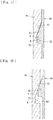
- the present embodiment includes a cushioning member 12 that is interposed between the first clutch member 4a and the second clutch member 4b and that can apply an urging force while allowing movements of the interlocking member 9 and the pressure member 5 by being compressed (spring is deformed) in the process in which the interlocking member 9 moves and the pressure member 5 moves from the inactive position toward the active position.
- the cushioning member 12 is composed of a spring that is set to a load such that the spring is compressed before the clutch spring 11 starts to be compressed. As illustrated in Figs.
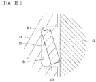
- the cushioning member 12 is assembled by being accommodated in an accommodation recessed portion 4c that is formed in a surface at which the first clutch member 4a and the second clutch member 4b face each other (to be specific, a surface of the first clutch member 4a facing the second clutch member 4b).
- the accommodation recessed portion 4c is composed of an annular groove
- the cushioning member 12 is composed of a coned-disc spring having an annular shape conformed to the shape of the groove.
- the accommodation recessed portion 4c is composed of a groove having a wall surface 4ca on the radially-inner side and a wall surface 4cb on the radially-outer side; and the cushioning member 12, which is composed of an annular spring, is conformed to the shape of the groove and fitted into the accommodation recessed portion 4c.
- the back-torque transmitting cam is formed in a plurality of annular shapes in a surface at which the first clutch member 4a and the second clutch member 4b face each other.
- the accommodation recessed portion 4c is formed in a concentric circular shape at a position that is adjacent to the back-torque transmitting cam (in the present embodiment, on the radially-inner side of the position where the back-torque transmitting cam is formed).
- the accommodation recessed portion 4c is formed in a concentric circular shape at a position on the radially-inner side of the position of the back-torque transmitting cam.
- the accommodation recessed portion 4c may be formed in a concentric circular shape at a position on the radially-outer side of the position of the back-torque transmitting cam.
- the cushioning member 12 may be configured to apply an urging force to a part (disc pack) where the drive-side clutch plates 6 and the driven-side clutch plates 7 are stacked, in a direction such that the drive-side clutch plates 6 and the driven-side clutch plates 7 are pressed against each other.
- the function the cushioning member 12 according to the present embodiment will be described in comparison with an existing device that does not have the cushioning member 12.
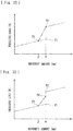
- the function of a case where the cushioning member 12 is not provided, in contrast to the present embodiment will be described with reference to the graph of Fig. 32 (a graph having the movement amount (mm) of the interlocking member 9 along the horizontal axis and the pressing load (N) generated in the interlocking member 9 along the vertical axis).
- the graph of Fig. 32 a graph having the movement amount (mm) of the interlocking member 9 along the horizontal axis and the pressing load (N) generated in the interlocking member 9 along the vertical axis.
- P1 indicates the pressing load of the interlocking member 9 at a time when the deformation amount (compression amount) of the release spring m is the maximum (at a time of reaching the maximum load of the release spring m), and P2 indicates the pressing load of the interlocking member 9 at a time when the clutch spring 11 starts to be deformed (at a time of reaching a set load of the clutch spring 11).
- P3 indicates the pressing load of the interlocking member 9 at a time when the cushioning member 12 starts to be deformed (at a time of reaching a set load of the cushioning member 12).
- the release spring m is deformed and the clutch spring 11 is not deformed (that is, the interlocking member 9 and the pressure member 5 move together) until the movement amount of the interlocking member 9 reaches ⁇ , and, when the movement amount of the interlocking member 9 reaches ⁇ , although the pressing load (N) increases from P1 to P2, the interlocking member 9 stops moving, and becomes a dead zone.
- the present embodiment includes the cushioning member 12 that is composed of a spring that is set to a load such that the spring is compressed before the clutch spring 11 starts to be compressed in the process in which the interlocking member 9 moves (a spring whose set load is set to P3). Therefore, as illustrated in Fig. 22 , the cushioning member 12 starts to be compressed (starts to be deformed) from the time when the movement amount of the interlocking member 9 reaches ⁇ , and compression is continued to the time when and the pressing load reaches P2.
- the cushioning member 12 is compressed from the time when the movement amount of the interlocking member 9 becomes ⁇ and the pressing load (N) reaches P3, and subsequently, the clutch spring 11 starts to be deformed (starts to be compressed) as the movement amount of the interlocking member 9 reaches ⁇ and the pressing load (N) becomes P2.
- the pressing load (N) becomes the set load of the release spring m and the release spring m starts to be deformed (starts to be compressed).
- the cushioning member 12 starts to be deformed (starts to be compressed).
- the release spring m reaches the maximum load and the pressing load (N) reaches the set load (P2) of the clutch spring 11, and thereby the clutch spring 11 starts to be deformed (starts to be compressed).
- the clutch spring 11 reaches the maximum load (the upper limit of the working load)
- the clutch spring 11 continues to be compressed (continues to be deformed) due to the movement of the interlocking member 9.
- the cushioning member 12 is continuously compressed (deformed) to allow the movement of the interlocking member 9 in the process in which the pressing load increases from P3 to P2. Therefore, it is possible to reduce the dead zone of the existing device and to smoothly and continuously move the weight member 8 and the interlocking member 9. Thus, it is possible to suppress shock when the clutch is engaged and to suppress feeling of surprise when power is transmitted.
- the cushioning member 12 is configured to be continuously compressed (continues to be deformed) when the pressing load (N) is between P3 and P2.
- the cushioning member 12 may be set so that: the cushioning member 12 starts to be compressed (starts to be deformed) from the time when the movement amount of the interlocking member 9 becomes ⁇ and the pressing load (N) reaches P3; and the cushioning member 12 is continuously compressed (continued to be deformed) until the time when the pressing load (N) becomes P4 that is lower than P2.
- the present embodiment includes the cushioning member 12 that is interposed between the first clutch member 4a and the second clutch member 4b and that can apply an urging force while allowing movements of the interlocking member 9 and the pressure member 5 by being compressed in the process in which the interlocking member 9 moves and the pressure member 5 moves from the inactive position toward the active position. Therefore, with the present embodiment, it is possible to suppress feeling of surprise when power is transmitted and to improve operability while efficiently utilizing a space that is obtained by the arrangement of the first clutch member 4a and the second clutch member 4b.
- the cushioning member 12 is composed of a spring that is set to a load such that the spring is compressed before the clutch spring 11 starts to be compressed. Therefore, it is possible to more reliably suppress feeling of surprise when power is transmitted. In particular, it is possible to set in various ways the feeling (driving-start feeling) when power is transmitted in accordance with the type of a vehicle to which the present device is applied by appropriately setting the set load and the working load of the cushioning member 12.
- the cushioning member 12 according to the present embodiment is accommodated in the accommodation recessed portion 4c formed in a surface at which the first clutch member 4a and the second clutch member 4b face each other. Therefore, it is possible to avoid positional displacement of the cushioning member 12 that may occur if the cushioning member 12 is involved when the first clutch member 4a moves relative to the second clutch member 4b.
- the accommodation recessed portion 4c according to the present embodiment is formed in a surface of the first clutch member 4a facing the second clutch member 4b.
- the accommodation recessed portion 4c may be formed in a surface of the second clutch member 4b facing the first clutch member 4a.
- the accommodation recessed portion 4c according to the present embodiment is composed of an annular groove
- the cushioning member 12 is composed of a spring having an annular shape conformed to the shape of the groove. Therefore, it is possible to apply an urging force generated by the cushioning member 12 to the second clutch member 4b and the like substantially uniformly, and it is possible to apply the urging force stably.
- the back-torque transmitting cam according to the present embodiment is formed in a plurality of annular shapes in a surface at which the first clutch member 4a and the second clutch member 4b face each other, and the accommodation recessed portion 4c is formed in a concentric circular shape at a position that is adjacent to the back-torque transmitting cam. Therefore, it is possible to enable the back-torque transmitting cam to reliably and stably move the second clutch member 4b and to enable the cushioning member 12 to reliably and stably apply an urging force.
- the bearing holding member C is composed of a cylindrical member one end of which is open, and the open end portion Ca is fitted into and attached to the recessed portion 4d formed in the clutch member (the first clutch member 4a) (attached in a socket-and-spigot joint state). Therefore, it is easy to assemble the bearing holding member C, and it is possible to stably operate the bearing holding member C when a shifting operation is performed.
- the power transmission device includes: the release spring m that can apply an urging force to the pressure member 5 while allowing movements of the interlocking member 9 and the pressure member 5 until the drive-side clutch plates 6 and the driven-side clutch plates 7 reach an engaged state before the drive-side clutch plates 6 and the driven-side clutch plates 7 are pressed against each other; and the release spring m is attached between the bearing holding member C and the pressure member 5, applies an urging force to the pressure member 5, and can apply an urging force to the bearing holding member C to transmit the urging force to the activation member 10. Therefore, it is possible to use the release spring m also as a spring for preventing play of shift operation means, and to reduce the number of components.
- the release spring m according to the present embodiment is composed of a coned-disc spring that can generate an urging force due to a displacement between the middle part ma and the peripheral edge part mb, the middle part ma is attached to the bearing holding member C, and the peripheral edge part mb is attached to the pressure member 5. Therefore, it is possible to stably apply urging forces of the release spring m to both of the bearing holding member C and the pressure member 5.
- the clutch member according to the present embodiment includes the first clutch member 4a that is coupled to the output shaft 3 (output member), the second clutch member 4b to which the driven-side clutch plates 7 are attached, and a back-torque transmitting cam that can press the drive-side clutch plates 6 and the driven-side clutch plates 7 against each other by moving the second clutch member 4b when a rotational force is input to the first clutch member 4a via the output shaft 3 (output member); and the recessed portion 4d is formed in the first clutch member 4a.
- the back-torque transmitting cam can move the second clutch member 4b in a direction toward the interlocking member 9 to maintain contact between the interlocking member 9 and the weight member 8. Therefore, it is possible to press the drive-side clutch plates 6 and the driven-side clutch plates 7 against each other to transmit a rotational force on the wheel side to the engine side to apply an engine brake, and it is possible to stably perform activation by the weight member 8 when an engine brake is applied.
- the back-torque transmitting cam according to the present embodiment is composed of the cam surfaces (K1, T1) respectively formed in the first clutch member 4a and the second clutch member 4b integrally, and the cam surfaces (K1, T1) are respectively formed in the mating surfaces of the first clutch member 4a and the second clutch member 4b. Therefore, it is possible to enable the back-torque transmitting cam to reliably and smoothly move the second clutch member 4b.
- the power transmission device includes a press-contact assisting cam that is composed of the inclined surface 4aa of the first clutch member 4a and the inclined surface 5a of the pressure member 5 facing each other and that increases the press-contact force between the drive-side clutch plates 6 and the driven-side clutch plates 7 when a rotational force input to the input gear 1 (input member) becomes capable of being transmitted to the output shaft 3 (output member). Therefore, it is possible to apply a press-contact force due to the press-contact assisting cam in addition to a press-contact force due to the movement of the weight member 8 by a centrifugal force, and it is possible to press the drive-side clutch plates 6 and the driven-side clutch plates 7 against each other more smoothly and more reliably.
- the power transmission device includes a back-torque limiter cam that is composed of the inclined surface 4ab of the first clutch member 4a and the inclined surface 5b of the pressure member 5 facing each other, and that can release the press-contact force between the drive-side clutch plates 6 and the driven-side clutch plates 7 when the rotational speed of the output shaft 3 (output member) exceeds the rotational speed of the input gear 1 (input member) and the clutch member (the first clutch member 4a) and the pressure member 5 rotate relative to each other.
- a back-torque limiter cam that is composed of the inclined surface 4ab of the first clutch member 4a and the inclined surface 5b of the pressure member 5 facing each other, and that can release the press-contact force between the drive-side clutch plates 6 and the driven-side clutch plates 7 when the rotational speed of the output shaft 3 (output member) exceeds the rotational speed of the input gear 1 (input member) and the clutch member (the first clutch member 4a) and the pressure member 5 rotate relative to each other.
- the present embodiment includes: a back-torque transmitting cam that can move the second clutch member 4b to press the drive-side clutch plates 6 and the driven-side clutch plates 7 against each other when a rotational force is input to the first clutch member 4a via the output shaft 3 (output member); and a torque transmitting portion that is formed in each of the first clutch member 4a and the second clutch member 4b and that can transmit a rotational force, which has been transmitted to the second clutch member 4b, to the first clutch member 4a without using the back-torque transmitting cam (the cam surface K1 and the cam surface T1).
- the power transmission device includes the movement-amount limiting portion that is formed in each of the first clutch member 4a and the second clutch member 4b and that limits the movement amount of the second clutch member 4b due to the back-torque transmitting cam. Therefore, it is possible to enable the back-torque transmitting cam to move the second clutch member 4b in a set range.
- the protruding portion F is formed in either one of the first clutch member 4a and the second clutch member 4b, the torque transmitting portion is composed of the one side surface F1 of protruding portion F and the first contact surface G1 that receives a rotational force by contacting the one side surface F1, and the movement-amount limiting portion is composed of the other side surface F2 of the protruding portion F and the second contact surface G2 that can limit the movement amount by contacting the other side surface F2. Therefore, the protruding portion F can function as both of the torque transmitting portion and the movement-amount limiting portion.
- the present embodiment has been described.
- the present invention is not limited to these.
- the present invention may be applied to a power transmission device in which a weight member 8 is disposed movably in a housing portion 2a of a clutch housing 2.
- the power transmission device includes, as with the embodiment described above, a first clutch member 4a, a second clutch member 4b, a back-torque transmitting cam, and a cushioning member 12 interposed between the first clutch member 4a and the second clutch member 4b.
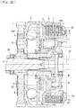
- Fig. 25 illustrates an embodiment in which a cushioning member 12 is attached to a surface of the first clutch member 4a facing the second clutch member 4b.
- Fig. 26 illustrates an embodiment in which a cushioning member 12 that applies an urging force to a part (disc pack) of the first clutch member 4a where the drive-side clutch plates 6 and the driven-side clutch plates 7 are stacked is attached to the surface.
- a bearing holding member C' can be moved by an activation member 10', and a release spring m' is composed of a coil spring that is attached to both of the bearing holding member C' and the pressure member 5.
- the cushioning member 12 composed of a coned-disc spring
- another elastic member may be used instead of the cushioning member 12 composed of a coned-disc spring.
- a cushioning member 12' composed of a wave spring may be disposed in an accommodation recessed portion 4c.
- the wave spring is composed of a C-shaped member having a cutout portion 12'a in a part of an annular shape, has a wave shape with respect to the thickness direction t, and can generate an elastic force.
- the wave spring is interposed between the first clutch member 4a and the second clutch member 4b, and can apply an urging force while allowing movements of the interlocking member 9 and the pressure member 5 by being compressed in the process in which the interlocking member 9 moves and the pressure member 5 moves from the inactive position toward the active position.
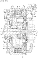
- the bearing holding member C has a plurality of (in the present embodiment, three) communication holes Cc formed in a side wall thereof and allows oil supplied to the inside of the bearing holding member C to flow to the outside via an oil flow path r.
- An activation member 10" is engaged with a roller bearing B1 of the bearing holding member C, and can move the pressure member 5 between the active position and the inactive position by moving in the left-right direction in the figure due to an operation by a driver or by working of an actuator.
- a back-torque transmitting cam (a cam surface K1 and a cam surface T1) may be disposed in an outer peripheral edge part of each of a first clutch member 4a and a second clutch member 4b.
- the back-torque transmitting cam is disposed in the outer peripheral edge part of each of the first clutch member 4a and the second clutch member 4b, the function of the cam can be enhanced, and the moving force of the second clutch member 4b can be set to be large.
- a cushioning member 12 composed of a coned-disc spring is disposed on the radially-inner side of the back-torque transmitting cam (the cam surface K1 and the cam surface T1).
- a cushioning member 12' composed of a wave spring, instead of a coned-disc spring, may be disposed.
- the bearing holding member C is composed of a cylindrical member one end of which is open, and the open end portion Ca is fitted into and attached to the recessed portion 4d formed in the clutch member (the first clutch member 4a).
- a bearing holding member having another shape may be used, and an attachment structure that differs from a configuration (so-called socket-and-spigot joint) such that the bearing holding member is fitted into a recessed portion formed in the clutch member may be used.
- the power transmission device according to the present invention can be applied to various multiple-disc clutch power transmission devices for, in addition to a motorcycle, an automobile, a three-wheeled or four-wheeled ATV, a general-purpose machine, and the like.
- the clutch member can be applied to a power transmission device having a different outer shape or having another additional function, as long as the power transmission device includes a first clutch member that is coupled to the output member, a second clutch member to which the driven-side clutch plates are attached, a back-torque transmitting cam that is capable of pressing the drive-side clutch plates and the driven-side clutch plates against each other by moving the second clutch member when a rotational force is input to the first clutch member via the output member, and a cushioning member that is interposed between the first clutch member and the second clutch member and that is capable of applying an urging force while allowing movements of the interlocking member and the pressure member by being compressed in the process in which the interlocking member moves and the pressure member moves from the inactive position to the active position.
Landscapes
- Engineering & Computer Science (AREA)
- General Engineering & Computer Science (AREA)
- Mechanical Engineering (AREA)
- Chemical & Material Sciences (AREA)
- Combustion & Propulsion (AREA)
- Transportation (AREA)
- Mechanical Operated Clutches (AREA)
- One-Way And Automatic Clutches, And Combinations Of Different Clutches (AREA)
Abstract
Description
- The present invention relates to a power transmission device that can appropriately transmit or stop transmitting rotational power of an input member to an output member.
- In general, a motorcycle has a power transmission device that is used to appropriately transmit or stop transmitting the driving power of an engine to a transmission and a driving wheel. The power transmission device includes an input member coupled to the engine side, an output member coupled to the transmission and driving wheel side, a clutch member coupled to an output member, and a pressure member that is capable of moving toward or away from the clutch member. The power transmission device is configured to transmit power by moving the pressure member toward the clutch member to press a drive-side clutch plate and a driven-side clutch plate against each other, and is configured to stop transmitting the power by moving the pressure member away from the clutch member to release a press-contact force between the drive-side clutch plate and the driven-side clutch plate.
- Among existing power transmission devices, as disclosed in, for example,
PTL 1, a power transmission device including a weight member has been proposed. The weight member can press a drive-side clutch plate and a driven-side clutch plate against each other by moving from a radially-inner position to a radially-outer position in a groove portion due to a centrifugal force that is generated as a clutch housing rotates. With the existing power transmission device, because the clutch housing rotates as the engine is driven, it is possible to apply a centrifugal force to the weight member and to transmit the driving power of the engine to a wheel by pressing the drive-side clutch plate and the driven-side clutch plate against each other. - The existing power transmission device further includes: a release spring that is compressed as an interlocking member moves and the pressure member moves from an inactive position toward an active position and that can apply an urging force while allowing movements of the interlocking member and the pressure member until the drive-side clutch plate and the driven-side clutch plate reach an engaged state before being pressed against each other; and a clutch spring that is compressed in a process in which the interlocking member moves after the drive-side clutch plate and the driven-side clutch plate have reached the engaged state and that can apply a press-contact force between the drive-side clutch plate and the driven-side clutch plate while allowing movement of the interlocking member.
- PTL 1:
Japanese Unexamined Patent Application Publication No. 2017-155884 - However, the existing power transmission device has the following problem. If the difference between a load (maximum load) at the time when compression of the release spring has been finished (see P1 in
Fig. 32 ) and a load (set load) at the time when compression of the clutch spring is started (see P2 in the figure) is large, in a process in which the interlocking member moves and the pressure member moves from the inactive position toward the active position as the rotational speed of the engine increases, a dead zone in which the movement of the interlocking member stops (stops while remaining at the movement amount α in the figure) occurs after compression of the release spring has been finished and before compression of the clutch spring is started. - Then, when the rotational speed of the engine increases further and the pressing load applied to the interlocking member reaches the set load of the clutch spring (at the time of P2 in the figure), compression of the clutch spring is started, thus the interlocking member starts moving again, and the dead zone is passed through. However, because the clutch plates are pressed against each other and the power is transmitted after the dead zone has been passed through, feeling of surprise occurs when power is transmitted and operability may be affected.
- The present applicant has examined a power transmission device in which a clutch member is divided into two so that an engine brake can be applied satisfactorily. The power transmission device includes a first clutch member that is coupled to an output member, a second clutch member to which a driven-side clutch plate is attached, and a back-torque transmitting cam that can press a drive-side clutch plate and the driven-side clutch plate against each other by moving the second clutch member when a rotational force is input to the first clutch member via the output member. In disposing means for suppressing the feeling of surprise, the present applicant has eagerly examined effective utilization of a space that is obtained by the arrangement of the first clutch member and the second clutch member.
- The present invention has been made in consideration of such circumstances, and an object thereof is to provide a power transmission device that can suppress feeling of surprise when power is transmitted and can improve operability while efficiently utilizing a space that is obtained by the arrangement of a first clutch member and a second clutch member.
- According to an invention described in
Claim 1, a power transmission device includes: a clutch housing that rotates together with an input member that is rotated by driving power of an engine of a vehicle and to which a plurality of drive-side clutch plates are attached; a clutch member to which a plurality of driven-side clutch plates that are formed alternately with the drive-side clutch plates of the clutch housing are attached and that is coupled to an output member that is capable of rotating a wheel of the vehicle; a pressure member that is movable between an active position at which the pressure member presses the drive-side clutch plates and the driven-side clutch plates against each other to be able to transmit the driving power of the engine to the wheel and an inactive position at which the pressure member releases a press-contact force between the drive-side clutch plates and the driven-side clutch plates to be able to stop transmitting the driving power of the engine to the wheel; a weight member that is disposed in a groove portion extending in a radial direction of the clutch housing and that is movable from a radially-inner position to a radially-outer position in the groove portion due to a centrifugal force that is generated as the clutch housing rotates; an interlocking member that is capable of moving the pressure member from the inactive position to the active position as the weight member moves from the radially-inner position to the radially-outer position; a release spring that is capable of holding the pressure member at the inactive position, that is compressed as the interlocking member moves and the pressure member moves from the inactive position toward the active position, and that is capable of applying an urging force while allowing movements of the interlocking member and the pressure member until the drive-side clutch plates and the driven-side clutch plates reach an engaged state before the drive-side clutch plates and the driven-side clutch plates are pressed against each other; and a clutch spring that is compressed in a process in which the interlocking member moves after the drive-side clutch plates and driven-side clutch plates have reached the engaged state and that is capable of applying a press-contact force between the drive-side clutch plates and the driven-side clutch plates while allowing movement of the interlocking member. The clutch member includes a first clutch member that is coupled to the output member, a second clutch member to which the driven-side clutch plates are attached, a back-torque transmitting cam that is capable of pressing the drive-side clutch plates and the driven-side clutch plates against each other by moving the second clutch member when a rotational force is input to the first clutch member via the output member, and a cushioning member that is interposed between the first clutch member and the second clutch member and that is capable of applying an urging force while allowing movements of the interlocking member and the pressure member by being compressed in a process in which the interlocking member moves and the pressure member moves from the inactive position toward the active position. - According to an invention described in
Claim 2, in the power transmission device described inClaim 1, the cushioning member is composed of a spring that is set to a load such that the spring is compressed before the clutch spring starts to be compressed. - According to an invention described in
Claim 3, in the power transmission device according toClaim - According to an invention described in
Claim 4, in the power transmission device according toClaim 3, the accommodation recessed portion is composed of an annular groove, and the cushioning member is composed of a spring having an annular shape conformed to a shape of the groove. - According to an invention described in
Claim 5, in the power transmission device according toClaim 4, the back-torque transmitting cam is formed in a plurality of annular shapes in the surface at which the first clutch member and the second clutch member face each other, and the accommodation recessed portion is formed in a concentric circular shape at a position that is adjacent to the back-torque transmitting cam. - With the invention described in
Claim 1, it is possible to suppress feeling of surprise when power is transmitted and to improve operability while efficiently utilizing a space that is obtained by the arrangement of the first clutch member and the second clutch member, because the power transmission device includes the cushioning member that is interposed between the first clutch member and the second clutch member and that is capable of applying an urging force while allowing movements of the interlocking member and the pressure member by being compressed in a process in which the interlocking member moves and the pressure member moves from the inactive position toward the active position. - With the invention described in
Claim 2, it is possible to more reliably suppress feeling of surprise when power is transmitted, because the cushioning member is composed of a spring that is set to a load such that the spring is compressed before the clutch spring starts to be compressed. - With the invention described in
Claim 3, it is possible to avoid positional displacement of the cushioning member that may occur if the cushioning member is involved when the first clutch member moves relative to the second clutch member, because the cushioning member is accommodated in an accommodation recessed portion that is formed in a surface at which the first clutch member and the second clutch member face each other. - With the invention described in
Claim 4, it is possible to apply an urging force generated by the cushioning member to the second clutch member and the like substantially uniformly, and it is possible to apply the urging force stably, because the accommodation recessed portion is composed of an annular groove, and the cushioning member is composed of a spring having an annular shape conformed to a shape of the groove. - With the invention described in
Claim 5, it is possible to enable the back-torque transmitting cam to reliably and stably move the second clutch member and to enable the cushioning member to reliably and stably apply an urging force, because the back-torque transmitting cam is formed in a plurality of annular shapes in the surface at which the first clutch member and the second clutch member face each other, and the accommodation recessed portion is formed in a concentric circular shape at a position that is adjacent to the back-torque transmitting cam. -
- [
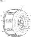
Fig. 1] Fig. 1 is an external view of a power transmission device according to an embodiment of the present invention. - [
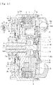
Fig. 2] Fig. 2 is a longitudinal sectional view illustrating the internal structure of the power transmission device. - [
Fig. 3] Fig. 3 is a schematic view of drive-side clutch plates, driven-side clutch plates, a back-torque transmitting cam, and the like of the power transmission device. - [
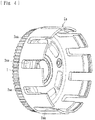
Fig. 4] Fig. 4 is a perspective view of a housing portion of a clutch housing of the power transmission device. - [
Fig. 5] Fig. 5 is a perspective view of a cover portion of the clutch housing of the power transmission device. - [
Fig. 6] Fig. 6 is a three-side view of a first clutch member of the power transmission device. - [
Fig. 7] Fig. 7 is a three-side view of a second clutch member of the power transmission device. - [
Fig. 8] Fig. 8 is a three-side view of a pressure member of the power transmission device. - [
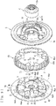
Fig. 9] Fig. 9 is a perspective view illustrating the first clutch member, the second clutch member, the pressure member, and a bearing holding member of the power transmission device before being assembled. - [
Fig. 10] Fig. 10 is a perspective view illustrating the first clutch member, the second clutch member, the pressure member, and the bearing holding member of the power transmission device before being assembled. - [
Fig. 11] Fig. 11 is a perspective view illustrating the first clutch member, the second clutch member, the pressure member, and the bearing holding member of the power transmission device after having been assembled. - [
Fig. 12] Fig. 12 is a three-side view of the bearing holding member of the power transmission device. - [
Fig. 13] Fig. 13 is a schematic view illustrating the function of a press-contact assisting cam of the power transmission device. - [
Fig. 14] Fig. 14 is a schematic view illustrating the function of a back-torque limiter cam of the power transmission device. - [
Fig. 15] Fig. 15 is a plan view of the first clutch member and the second clutch member of the power transmission device that are assembled together, illustrating a state in which one side surface of a protruding portion and a first contact surface (torque transmitting portion) are in contact with each other. - [
Fig. 16] Fig. 16 is a plan view of the first clutch member and the second clutch member of the power transmission device that are assembled together, illustrating a state in which and the other side surface of the protruding portion and a second contact surface (movement-amount limiting portion) are in contact with each other. - [
Fig. 17] Fig. 17 is a schematic view illustrating the function of the back-torque transmitting cam of the power transmission device in a state before the back-torque transmitting cam starts working. - [
Fig. 18] Fig. 18 is a schematic view illustrating the function of the back-torque transmitting cam of the power transmission device in a state after the back-torque transmitting cam has started working. - [
Fig. 19] Fig. 19 is a schematic view illustrating a cushioning member of the power transmission device accommodated in an accommodation recessed portion. - [
Fig. 20] Fig. 20 is a schematic view illustrating a state in which a release spring of the power transmission device applies urging forces to both of the bearing holding member and the pressure member. - [
Fig. 21] Fig. 21 is a three-side view of the release spring of the power transmission device. - [
Fig. 22] Fig. 22 is a graph representing the movement amount and the pressing load of an interlocking member of the power transmission device. - [
Fig. 23] Fig. 23 is a graph representing the movement amount and the pressing load of an interlocking member of a power transmission device according to another embodiment of the present invention. - [
Fig. 24] Fig. 24 is a longitudinal sectional view of a power transmission device according to another embodiment of the present invention. - [
Fig. 25] Fig. 25 is a longitudinal sectional view of a power transmission device according to another embodiment of the present invention. - [
Fig. 26] Fig. 26 is a longitudinal sectional view of a power transmission device according to another embodiment of the present invention. - [
Fig. 27] Fig. 27 is a longitudinal sectional view of a power transmission device according to another embodiment of the present invention (in which acushioning member 12' is disposed). - [
Fig. 28] Fig. 28 shows a plan view and a side view of the cushioning member of the power transmission device. - [
Fig. 29] Fig. 29 is a perspective view of the cushioning member of the power transmission device. - [
Fig. 30] Fig. 30 is a longitudinal sectional view of a power transmission device according to another embodiment of the present invention (in which a back-torque transmitting cam is disposed at an outer edge of afirst clutch member 4a and a cushioning member composed of a coned-disc spring is disposed). - [
Fig. 31] Fig. 31 is a longitudinal sectional view of a power transmission device according to another embodiment of the present invention (in which a back-torque transmitting cam is disposed at an outer edge of a firstclutch member 4a and a cushioning member composed of a wave spring is disposed). - [
Fig. 32] Fig. 32 is a graph representing the movement amount and the pressing load of an interlocking member of an existing power transmission device. Description of Embodiments - Hereafter, an embodiment of the present invention will be described in detail with reference to the drawings.
A power transmission device according to the present embodiment is a device that is disposed in a vehicle, such as a motorcycle, and is used to appropriately transmit or to stop transmitting the driving power of an engine to a transmission or toward the driving wheel side. As illustrated inFigs. 1 to 12 , the power transmission device mainly includes: aclutch housing 2 in which an input gear 1 (input member) that is rotated by the driving power of the engine of the vehicle is formed; a clutch member (a firstclutch member 4a and a secondclutch member 4b); apressure member 5 attached on the right side inFig. 2 of the clutch member (the firstclutch member 4a and the secondclutch member 4b); a plurality of drive-sideclutch plates 6; a plurality of driven-sideclutch plates 7; aweight member 8 that is composed of steel ball members that can move (roll) in the radial direction in theclutch housing 2; an interlockingmember 9; and anactivation member 10 that can be activated by hand or by an actuator (not shown). The symbol S in the figure shows a spring damper, the symbol B1 shows a roller bearing, and the symbols B2 and B3 respectively show thrust bearings. - The
input gear 1 can rotate around anoutput shaft 3 when the driving power (rotational force) transmitted from the engine is input. Theinput gear 1 is coupled to theclutch housing 2 via a rivet R and the like. Theclutch housing 2 includes ahousing portion 2a that is composed of a cylindrical member whose right side inFig. 2 is open and that is coupled to theinput gear 1, and acover portion 2b that is attached so as to close the opening of thehousing portion 2a. Theclutch housing 2 can rotate together with the rotation of theinput gear 1 due to the driving power of the engine. - As illustrated in
Fig. 4 , a plurality of cutouts 2aa are formed in thehousing portion 2a of theclutch housing 2 so as to be arranged in the circumferential direction, and the plurality of drive-sideclutch plates 6 are attached to be fitted to the cutouts 2aa. Each of the drive-sideclutch plates 6 is composed of a substantially annular plate material, and is configured to be able to rotate together with the rotation of theclutch housing 2 and to slide in the axial direction (the left-right direction inFig. 2 ). - Moreover, as illustrated in
Fig. 5 , a plurality of groove portions 2ba extending in the radial direction of thecover portion 2b are formed in the bottom surface of thecover portion 2b of theclutch housing 2. Theweight member 8 is disposed in each of the groove portions 2ba. In a state in which theclutch housing 2 is stopped (an engine stop or idling state) and in a state in which theclutch housing 2 is rotating at a low speed, theweight member 8 is located at a radially-inner position (the position shown inFig. 2 ). In a state in which theclutch housing 2 is rotating at a high speed, theweight member 8 is located at a radially-outer position. - The plurality of driven-side
clutch plates 7, which are formed alternately with the drive-sideclutch plates 6 of theclutch housing 2, are attached to the clutch member (the firstclutch member 4a and the secondclutch member 4b). The clutch member is coupled to the output shaft 3 (output member) that can rotate the wheel of the vehicle. The clutch member is configured by assembling two members, which are the firstclutch member 4a and the secondclutch member 4b. - As illustrated in
Fig. 6 , the firstclutch member 4a is composed of a disc-shaped member in which a flange surface 4ac is formed along the peripheral edge part thereof. The firstclutch member 4a is configured so that theoutput shaft 3 is inserted into an insertion hole 4ad (seeFigs. 2 and6 ) formed at the center thereof, and the firstclutch member 4a and theoutput shaft 3 are coupled to each other in the rotational direction as gears respectively formed therein mesh with each other. As illustrated inFigs. 6 ,9 , and10 , in the firstclutch member 4a, an inclined surface 4aa that constitutes a press-contact assisting cam and an inclined surface 4ab that constitutes a back-torque limiter cam are formed. - As illustrated in
Fig. 7 , the secondclutch member 4b is composed of an annular member, and is configured so that the driven-sideclutch plates 7 are attached by spline fitting to a spline-fitting portion 4ba (seeFigs. 2 and7 ) formed in an outer peripheral surface thereof. As illustrated inFigs. 9 to 11 , thepressure member 5 is assembled with the clutch member (the firstclutch member 4a and the secondclutch member 4b). The plurality of drive-sideclutch plates 6 and the driven-sideclutch plates 7 in an alternately stacked state are attached between aflange surface 5c of the pressure member 5 (seeFigs. 2 and8 ) and the flange surface 4ac of the firstclutch member 4a (seeFigs. 2 and6 ). - As illustrated in
Fig. 8 , thepressure member 5 is composed of a disc-shaped member in which theflange surface 5c is formed along the peripheral edge part thereof. Thepressure member 5 is movable between an active position at which thepressure member 5 presses the drive-sideclutch plates 6 and the driven-sideclutch plates 7 against each other to be able to transmit the driving power of the engine to the wheel and an inactive position (seeFig. 2 ) at which thepressure member 5 releases the press-contact force between the drive-sideclutch plates 6 and the driven-sideclutch plates 7 to be able to stop transmitting the driving power of the engine to the wheel. - To be more specific, as illustrated in
Figs. 7 and9 ,10 , the spline-fitting portion 4ba formed in the secondclutch member 4b has a protruding/recessed shape that is integrally formed along substantially the entire circumference of the outer peripheral side surface of the secondclutch member 4b. When the driven-sideclutch plates 7 are fitted into recessed grooves of the spline-fitting portion 4ba, movement of the driven-sideclutch plates 7 in the rotational direction is restricted while movement the driven-sideclutch plates 7 relative to the secondclutch member 4b in the axial direction is allowed, and the driven-sideclutch plates 7 can rotate together with the secondclutch member 4b. - The driven-side
clutch plates 7 are stacked alternately with the drive-sideclutch plates 6, and theclutch plates clutch plates clutch member 4b. When thepressure member 5 moves leftward inFig. 2 and theflange surface 5c thereof moves toward the flange surface 4ac of the firstclutch member 4a, bothclutch plates clutch housing 2 to theoutput shaft 3 via the secondclutch member 4b and the firstclutch member 4a. When thepressure member 5 moves rightward inFig. 2 and theflange surface 5c thereof and the flange surface 4ac of the firstclutch member 4a become separated from each other, the press-contact force between theclutch plates clutch member 4a and the secondclutch member 4b stop following the rotation of theclutch housing 2, and transmission of a rotational force to theoutput shaft 3 is stopped. - In the state in which the drive-side
clutch plates 6 and the driven-sideclutch plates 7 are pressed against each other, a rotational force (driving power of the engine) input to theclutch housing 2 is transmitted to the wheel side via the output shaft 3 (output member). In the state in which the press contact between the drive-sideclutch plates 6 and the driven-sideclutch plates 7 is released, a rotational force (driving power of the engine) input to theclutch housing 2 can be stopped to be transmitted to the output shaft 3 (output member). - Moreover, as illustrated in
Figs. 6 ,8 ,9 , and10 , in the present embodiment, the inclined surfaces 4aa and 4ab are formed in the firstclutch member 4a, andinclined surfaces pressure member 5. That is, the inclined surface 4aa and theinclined surface 5a contact each other to compose a press-contact assisting cam, and the inclined surface 4ab and theinclined surface 5b contact each other to compose a back-torque limiter cam. - As illustrated in
Fig. 13 , a rotational force in the direction a is applied to thepressure member 5 when the rotational speed of the engine increases and a rotational force input to theinput gear 1 and theclutch housing 2 becomes capable of being transmitted to theoutput shaft 3 via the firstclutch member 4a and the secondclutch member 4b (theweight member 8 is at the radially-outer position). Therefore, a force in the direction c in the figure is generated in thepressure member 5 due to the function of the press-contact assisting cam. Thus, theflange surface 5c of thepressure member 5 moves in a direction (leftward inFig. 2 ) further toward the flange surface 4ac of the firstclutch member 4a, and thepressure member 5 increases the press-contact force between the drive-sideclutch plates 6 and the driven-sideclutch plates 7. - On the other hand, while the vehicle is traveling, when the rotational speed of the
output shaft 3 exceeds the rotational speed of theinput gear 1 and theclutch housing 2 and a back torque in the direction b inFig. 14 is generated, due to the function of the back-torque limiter cam, thepressure member 5 is moved in the direction d in the figure to release the press-contact force between the drive-sideclutch plates 6 and the driven-sideclutch plates 7. Thus, it is possible to avoid damage to the power transmission device and the power source (engine side) due to the back torque. - The
weight member 8 is disposed in the groove portion 2ba extending in the radial direction of the clutch housing 2 (in the present embodiment, thecover portion 2b). Theweight member 8 moves from a radially-inner position (seeFig. 2 ) to a radially-outer position in the groove portion 2ba due to a centrifugal force, which is generated as theclutch housing 2 rotates, to press the drive-sideclutch plates 6 and the driven-sideclutch plates 7 against each other. That is, the rolling surface (bottom surface) of the groove portions 2ba on which theweight member 8 rolls has an upward inclination from the radially-inner position to the radially-outer position. When theclutch housing 2 is stopped, theweight member 8 is held at the radially-inner position due to an urging force of a release spring m. When theclutch housing 2 rotates, a centrifugal force is applied to theweight member 8 and moves theweight member 8 along the upward inclination to the radially-outer position as theclutch housing 2 reaches a predetermined rotational speed. - The interlocking
member 9 is composed of an annular member disposed in the clutch housing 2 (thecover portion 2b). The interlockingmember 9 is fitted and coupled to a groove portion formed in an inner peripheral surface of thecover portion 2b, is rotatable together with theclutch housing 2, and is movable in the left-right direction inFig. 2 . As theweight member 8 moves from the radially-inner position to the radially-outer position, the interlockingmember 9 moves leftward inFig. 2 against an urging force of the release spring m, and can press thepressure member 5 to move thepressure member 5 from the inactive position to the active position. - The
activation member 10 is composed of a member that can be operated by hand or by an actuator (seeFig. 2 ), and moves thepressure member 5 in a direction (rightward inFig. 2 ) such that the press-contact force between the drive-sideclutch plates 6 and the driven-sideclutch plates 7 can be released. When a shifting operation is performed, for example, by an operation on a clutch pedal, a clutch lever, or the like of the vehicle, or by working of an actuator, theactivation member 10 moves rightward inFig. 2 to contact thepressure member 5 via a bearing holding member C and moves thepressure member 5 from the active position to the inactive position. Thus, theactivation member 10 can disengage the clutch (stop transmitting the power) by releasing the press-contact force between the drive-sideclutch plates 6 and the driven-sideclutch plates 7. - As illustrated in
Fig. 2 , the bearing holding member C is coupled to theactivation member 10, and holds a bearing B1 interposed between theactivation member 10 and thepressure member 5. As illustrated inFig. 12 , the bearing holding member C is composed of a cylindrical member one end of which is open, and includes an open end portion C and a top portion Cb on the opposite side of the open end portion Ca. The bearing B1 according to the present embodiment is attached to the top portion Cb side in the bearing holding member C, and a cylindrical part extends from an increased-diameter part to the open end portion Ca. Although a ball bearing is used as the bearing B1 according to the present embodiment, for example, another bearing such as a needle bearing may be used. - Moreover, as illustrated in
Figs. 2 and20 , an open end portion Ca of the bearing holding member C according to the present embodiment is fitted into and attached to a recessedportion 4d formed in the clutch member (the firstclutch member 4a), and is assembled with an inner peripheral wall surface 4da of the recessedportion 4d by socket-and-spigot joint (fitting joint). The recessedportion 4d is composed of a circular depression having a shape similar to and a size substantially the same as the outer shape of the open end portion Ca (to be strict, a size slightly larger than the open end portion Ca). By fitting the bearing holding member C into the recessedportion 4d, positioning and centering relative to the power transmission device are performed. - In a shifting operation, when the
activation member 10 moves rightward inFig. 2 by, for example, an operation on a clutch pedal, a clutch lever, or the like of the vehicle or by working of an actuator, the bearing holding member C moves together and contacts thepressure member 5 to move thepressure member 5 from the active position to the inactive position. Thus, the clutch is disengaged (transmission of power is stopped) by releasing the press-contact force between the drive-sideclutch plates 6 and the driven-sideclutch plates 7. - The release spring m can hold the
pressure member 5 at the inactive position, and is compressed as the interlockingmember 9 moves and thepressure member 5 moves from the inactive position toward the active position. The release spring m can apply an urging force while allowing movements of the interlockingmember 9 and thepressure member 5 until the drive-sideclutch plates 6 and the driven-sideclutch plates 7 reach an engaged state before being pressed against each other (a state in which the distance between the drive-sideclutch plates 6 and the driven-sideclutch plates 7 is zero and immediately before power transmission due to pressed contact is performed). - Moreover, as illustrated in
Fig. 21 , the release spring m according to the present embodiment is composed of a coned-disc spring that can generate an urging force due to a displacement between a middle part ma and a peripheral edge part mb. As illustrated inFigs. 2 and20 , the middle part ma is attached to the top portion Cb of the bearing holding member C, and the peripheral edge part mb is attached to thepressure member 5. Thepressure member 5 has a projectingportion 5d that projects annularly, and the peripheral edge part mb of the release spring m is engaged with and attached to a ring-shaped member g (for example, a circlip and the like) attached to the projectingportion 5d. Thus, the release spring m according to the present embodiment is attached to both of the bearing holding member C and thepressure member 5, applies an urging force (an urging force in an orientation indicated by a numeral a2 inFig. 20 ) to thepressure member 5, and can apply an urging force (an urging force in an orientation indicated by a symbol a1 in the figure) to the bearing holding member C to transmit the urging force to theactivation member 10. - A
clutch spring 11 is composed of a coil spring interposed between the interlockingmember 9 and thepressure member 5. As the interlockingmember 9 moves, theclutch spring 11 can press thepressure member 5 to move thepressure member 5 in a direction such that the drive-sideclutch plates 6 and the driven-sideclutch plates 7 are pressed against each other. Moreover, when theactivation member 10 is working, theclutch spring 11 can absorb the pressing force that thepressure member 5 applies to the interlockingmember 9. - The
clutch spring 11 according to the present embodiment moves together with thepressure member 5 without being compressed (deformed), until the drive-sideclutch plates 6 and the driven-sideclutch plates 7 reach the engaged state described above. After the drive-sideclutch plates 6 and the driven-sideclutch plates 7 have reached the engaged state, theclutch spring 11 is compressed in the process in which the interlockingmember 9 moves, and can apply a press-contact force between the drive-sideclutch plates 6 and the driven-sideclutch plates 7 while allowing movement of the interlockingmember 9. - That is, when the
weight member 8 moves from the radially-inner position to the radially-outer position and the interlockingmember 9 is pressed by theweight member 8 as theclutch housing 2 rotates, the pressing force is transmitted to thepressure member 5 via theclutch spring 11, moves thepressure member 5 leftward inFig. 2 , and presses the drive-sideclutch plates 6 and the driven-sideclutch plates 7 against each other. When theactivation member 10 is activated in this state, although thepressure member 5 moves rightward in the figure due to the pressing force of theactivation member 10, the pressing force applied to the interlockingmember 9 is absorbed by theclutch spring 11, and the position of the interlocking member 9 (the position of the weight member 8) is maintained. - Here, the power transmission device according to the present embodiment includes a back-torque transmitting cam (cam surfaces K1 and T1) that can move the second
clutch member 4b to press the drive-sideclutch plates 6 and the driven-sideclutch plates 7 against each other, when a rotational force is input to the firstclutch member 4a via the output shaft 3 (output member). As illustrated inFigs. 6 ,7 ,9 , and10 , the back-torque transmitting cam is composed of cam surfaces (K1, T1) that are respectively integrally formed in mating surfaces of the firstclutch member 4a and the secondclutch member 4b (mating surfaces when combined). - As illustrated in
Figs. 6 and9 , the cam surface K1 is composed of a plurality of inclined surfaces formed along the entire circumference of the radially-inner side of the flange surface 4ac of the firstclutch member 4a (the mating surface with the secondclutch member 4b). The cam surface K1 is formed in one end surface of each of a plurality of groove portions K that are annularly formed along the peripheral edge part of the firstclutch member 4a. That is, the plurality of groove portions K are formed in the firstclutch member 4a so as to be arranged in the circumferential direction thereof, and one end surface of each groove portion K is an inclined surface that constitutes the cam surface K1 of the back-torque transmitting cam. The other end surface of each groove portion K is a wall surface K2 extending in the axial direction of the firstclutch member 4a. - As illustrated in
Figs. 7 and10 , the cam surface T1 is composed of a plurality of inclined surfaces formed along the entire circumference of the bottom surface of the secondclutch member 4b (the mating surface with the firstclutch member 4a). The cam surface T1 is formed in one end surface of each of a plurality of projecting portions T that are annularly formed along the bottom surface of the secondclutch member 4b. That is, the plurality of projecting portions T are formed in the secondclutch member 4b so as to be arranged in the circumferential direction thereof, and one end surface of each projecting portion T is an inclined surface that constitutes the cam surface T1 of the back-torque transmitting cam. The other end surface of each projecting portion T is a wall surface T2 extending in the axial direction of the secondclutch member 4b. - As illustrated in
Fig. 17 , when the projecting portion T is fitted into the groove portion K to combine the firstclutch member 4a and the secondclutch member 4b with each other, the cam surface K1 and the cam surface T1 face each other to constitute the back-torque transmitting cam, and the wall surface K2 and the wall surface T2 face each other with a predetermined distance therebetween. When a rotational force is input to the firstclutch member 4a via theoutput shaft 3, because the firstclutch member 4a rotates relative to the secondclutch member 4b, as illustrated inFig. 18 , the secondclutch member 4b is moved rightward inFigs. 2 and18 relative to the firstclutch member 4a due to the cam function of the cam surface K1 and the cam surface T1. - As illustrated in
Fig. 7 , a pressing portion 4bb is formed in the secondclutch member 4b on an extension line of the spline-fitting portion 4ba. When the secondclutch member 4b moves rightward inFig. 2 , the pressing portion 4bb presses in the same direction the driven-sideclutch plate 7 on the leftmost side in the figure, which is one of the drive-sideclutch plates 6 and the driven-sideclutch plates 7 that are attached in a stacked state. Thus, even when thepressure member 5 is at the inactive position, it is possible to press the drive-sideclutch plates 6 and the driven-sideclutch plates 7 against each other, and, when a rotational force is input from the output shaft 3 (output member), it is possible to transmit the rotational force to the engine side to apply an engine brake. - In particular, the back-torque transmitting cam according to the present embodiment can move the second
clutch member 4b in a direction toward the interlocking member 9 (rightward inFig. 2 ) to maintain contact between the interlockingmember 9 and theweight member 8. That is, when the back-torque transmitting cam starts working and moves the secondclutch member 4b rightward inFig. 2 , the back-torque transmitting cam presses the drive-sideclutch plates 6 and the driven-sideclutch plates 7 against each other and presses thepressure member 5 in the same direction. Therefore, the pressing force is transmitted to the interlockingmember 9 via theclutch spring 11, and contact between the interlockingmember 9 and theweight member 8 is maintained. - If the interlocking
member 9 and theweight member 8 are separated from each other when the back-torque transmitting cam is working, even when theweight member 8 subsequently moves between the radially-inner position and the radially-outer position as theclutch housing 2 rotates, it may not be possible for the interlockingmember 9 to follow the movement. In contrast, with the present embodiment, it is possible to maintain contact between the interlockingmember 9 and theweight member 8 even when the back-torque transmitting cam is working, and thus the interlockingmember 9 can stably follow the movement of theweight member 8. - Moreover, the plurality of the cam surfaces K1 and T1 of the back-torque transmitting cam according to the present embodiment are formed along the annular shape the driven-side
clutch plates 7 attached to the secondclutch member 4b. That is, the cam surfaces K1 and T1 are formed along the projected-image shape (annular shape) of the driven-sideclutch plates 7 that are pressed by the pressing portion 4bb when the back-torque transmitting cam works. Thus, due to the cam function of the back-torque transmitting cam, the pressing portion 4bb can apply to the driven-side clutch plates 7 a substantially uniform pressing force, and it is possible to press the drive-sideclutch plates 6 and the driven-sideclutch plates 7 against each other more efficiently. - Furthermore, the back-torque transmitting cam according to the present embodiment (a cam constituted by the cam surface K1 and the cam surface T1) can start working before the back-torque limiter cam (a cam constituted by the inclined surface 4ab and the
inclined surface 5b) starts working. That is, the clearance (the dimension of the gap) between the cam surface K1 and the cam surface T1 is smaller than the clearance (the dimension of the gap) between the inclined surface 4ab and theinclined surface 5b, and the back-torque transmitting cam can start working before the back-torque limiter cam starts working. - Moreover, the power transmission device according to the present embodiment includes: a torque transmitting portion that is formed in each of the first
clutch member 4a and the secondclutch member 4b and that can transmit a rotational force, which has been transmitted to the secondclutch member 4b, to the firstclutch member 4a without using the back-torque transmitting cam (the cam surfaces K1 and the cam surfaces T1); and a movement-amount limiting portion that is formed in each of the firstclutch member 4a and the secondclutch member 4b and that limits the movement amount of the secondclutch member 4b due to the back-torque transmitting cam (the cam surfaces K1 and the cam surfaces T1). - That is, as illustrated in
Figs. 6 and9 , a plurality of (in the present embodiment, three) protruding portions F are integrally formed in the firstclutch member 4a so as to be arranged at regular intervals in the circumferential direction. As illustrated inFigs. 7 and9 , projecting portions G extending inward are integrally formed in the secondclutch member 4b. As illustrated inFigs. 15 and16 , when the firstclutch member 4a and the secondclutch member 4b are assembled together, one protruding portion F is interposed between two projecting portions G, one side surface F1 of the protruding portion F and the contact surface (first contact surface G1) of one of the projecting portions G face each other, and the other side surface F2 of the protruding portion F and the contact surface (second contact surface G2) of the other projecting portion G face each other. - One side surface F1 of the protruding portion F formed in the first
clutch member 4a and the first contact surface G1 of the projecting portion G formed in the secondclutch member 4b constitute the torque transmitting portion according to the present embodiment. That is, when thepressure member 5 moves to the active position to press the drive-sideclutch plates 6 and the driven-sideclutch plates 7 against each other and the clutch is engaged (driving power is transmitted), while the wall surface K2 of the groove portion K and the wall surface T2 of the projecting portion T of the back-torque transmitting cam are maintained in a separated state (seeFig. 17 ), as illustrated inFig. 15 , one side surface F1 of the protruding portion F and the first contact surface G1 of the projecting portion G contact each other, and a rotational force of the secondclutch member 4b can be received and transmitted to the firstclutch member 4a. - The other side surface F2 of the protruding portion F formed in the first
clutch member 4a and the second contact surface G2 of the other projecting portion G formed in the secondclutch member 4b constitute the movement-amount limiting portion according to the present embodiment. That is, when a rotational force is input to the firstclutch member 4a via theoutput shaft 3, the firstclutch member 4a and the secondclutch member 4b rotate relative to each other. Therefore, the secondclutch member 4b moves (seeFig. 18 ) due to the cam function of the cam surface K1 of the groove portion K and the cam surface T1 of the projecting portion T of the back-torque transmitting cam. When the movement amount reaches a set value, as illustrated inFig. 16 , the other side surface F2 of the protruding portion F and the second contact surface G2 of the projecting portion G contact each other, rotation of the secondclutch member 4b relative to the firstclutch member 4a is restricted, and therefore it is possible to limit the movement amount of the secondclutch member 4b when the back-torque transmitting cam is working. - In the present embodiment, the protruding portion F is formed in the first
clutch member 4a, and the projecting portion G is formed in the secondclutch member 4b. Alternatively, the projecting portion G may be formed in the firstclutch member 4a, and the protruding portion F may be formed in the secondclutch member 4b. In this case, one side surface F1 of the protruding portion F formed in the secondclutch member 4b and the first contact surface G1 of one projecting portion G formed in the firstclutch member 4a constitute the torque transmitting portion according to the present embodiment. The other side surface F2 of the protruding portion F formed in the secondclutch member 4b and the second contact surface G2 of the other projecting portion G formed in the firstclutch member 4a constitute the movement-amount limiting portion according to the present embodiment. - Next, the function of the back-torque transmitting cam in the present embodiment will be described.
As illustrated inFig. 2 , when the engine is stopped or idling, theweight member 8 is at the radially-inner position and thepressure member 5 is at the inactive position, because the driving power of the engine is not transmitted to theinput gear 1 or the rotational speed of theinput gear 1 is low. At this time, when a rotational force is input to the firstclutch member 4a via the output shaft 3 (output member), due to the cam function of the back-torque transmitting cam, the secondclutch member 4b moves rightward in the figure, and the drive-sideclutch plates 6 and the driven-sideclutch plates 7 are pressed against each other to transmit a rotational force to the engine side. - When the vehicle starts to move after having been stopped or idling, the rotational speed of the
input gear 1 changes from a low rotational speed to a high rotational speed (middle rotational speed range), theweight member 8 is located between the radially-inner position and the radially-outer position and thepressure member 5 is located at the active position. At this time, when a rotational force is input to the firstclutch member 4a via the output shaft 3 (output member) as, for example, acceleration pedal is released on a downward slope, due to the cam function of the back-torque transmitting cam, the secondclutch member 4b moves rightward in the figure, and the drive-sideclutch plates 6 and the driven-sideclutch plates 7 are pressed against each other to transmit a rotational force to the engine side. - After the vehicle has started, when the vehicle accelerates and travels in a high speed range, the
weight member 8 is located at the radially-outer position and thepressure member 5 is located at the active position, because the rotational speed of theinput gear 1 is a high rotational speed. At this time, when a rotational force is input to the firstclutch member 4a via the output shaft 3 (output member) in response to shift down or the like, due to the cam function of the back-torque transmitting cam, the secondclutch member 4b moves rightward in the figure, and the drive-sideclutch plates 6 and the driven-sideclutch plates 7 are pressed against each other to transmit a rotational force to the engine side. - Here, the present embodiment includes a cushioning
member 12 that is interposed between the firstclutch member 4a and the secondclutch member 4b and that can apply an urging force while allowing movements of the interlockingmember 9 and thepressure member 5 by being compressed (spring is deformed) in the process in which the interlockingmember 9 moves and thepressure member 5 moves from the inactive position toward the active position. The cushioningmember 12 is composed of a spring that is set to a load such that the spring is compressed before theclutch spring 11 starts to be compressed. As illustrated inFigs. 2 ,3 , and19 , the cushioningmember 12 is assembled by being accommodated in an accommodation recessedportion 4c that is formed in a surface at which the firstclutch member 4a and the secondclutch member 4b face each other (to be specific, a surface of the firstclutch member 4a facing the secondclutch member 4b). - To be more specific, as illustrated in
Fig. 6 , the accommodation recessedportion 4c is composed of an annular groove, and the cushioningmember 12 is composed of a coned-disc spring having an annular shape conformed to the shape of the groove. As illustrated inFig. 19 , the accommodation recessedportion 4c is composed of a groove having a wall surface 4ca on the radially-inner side and a wall surface 4cb on the radially-outer side; and the cushioningmember 12, which is composed of an annular spring, is conformed to the shape of the groove and fitted into the accommodation recessedportion 4c. - As described above, the back-torque transmitting cam according to the present embodiment is formed in a plurality of annular shapes in a surface at which the first
clutch member 4a and the secondclutch member 4b face each other. As illustrated inFig. 6 , the accommodation recessedportion 4c is formed in a concentric circular shape at a position that is adjacent to the back-torque transmitting cam (in the present embodiment, on the radially-inner side of the position where the back-torque transmitting cam is formed). In the present embodiment, the accommodation recessedportion 4c is formed in a concentric circular shape at a position on the radially-inner side of the position of the back-torque transmitting cam. However, the accommodation recessedportion 4c may be formed in a concentric circular shape at a position on the radially-outer side of the position of the back-torque transmitting cam. In this case, as illustrated inFig. 24 , the cushioningmember 12 may be configured to apply an urging force to a part (disc pack) where the drive-sideclutch plates 6 and the driven-sideclutch plates 7 are stacked, in a direction such that the drive-sideclutch plates 6 and the driven-sideclutch plates 7 are pressed against each other. - Next, the function the cushioning
member 12 according to the present embodiment will be described in comparison with an existing device that does not have the cushioningmember 12.
First, the function of a case where the cushioningmember 12 is not provided, in contrast to the present embodiment, will be described with reference to the graph ofFig. 32 (a graph having the movement amount (mm) of the interlockingmember 9 along the horizontal axis and the pressing load (N) generated in the interlockingmember 9 along the vertical axis). In the graph ofFig. 32 , P1 indicates the pressing load of the interlockingmember 9 at a time when the deformation amount (compression amount) of the release spring m is the maximum (at a time of reaching the maximum load of the release spring m), and P2 indicates the pressing load of the interlockingmember 9 at a time when theclutch spring 11 starts to be deformed (at a time of reaching a set load of the clutch spring 11). InFigs. 22 and 23 , P3 indicates the pressing load of the interlockingmember 9 at a time when the cushioningmember 12 starts to be deformed (at a time of reaching a set load of the cushioning member 12). - In the process in which the rotational speed of the engine increases and the
weight member 8 moves from the radially-inner position to the radially-outer position to move the interlockingmember 9, the release spring m is deformed and theclutch spring 11 is not deformed (that is, the interlockingmember 9 and thepressure member 5 move together) until the movement amount of the interlockingmember 9 reaches α, and, when the movement amount of the interlockingmember 9 reaches α, although the pressing load (N) increases from P1 to P2, the interlockingmember 9 stops moving, and becomes a dead zone. - When the pressing load (N) reaches P2 (the set load of the clutch spring 11) from such a state, the
clutch spring 11 starts to be deformed, and the pressing load (N) increases in accordance with the movement of the interlockingmember 9. Thus, the interlockingmember 9 and thepressure member 5 stop until the pressing load (N) reaches from P1 to P2, and, as soon as the pressing load (N) reaches P2, theclutch spring 11 starts to be compressed, the clutch plates (the drive-sideclutch plates 6 and the driven-side clutch plates 7) are pressed against each other to transmit power, and thus a feeling of surprise occurs when power is transmitted. - In contrast, the present embodiment includes the cushioning
member 12 that is composed of a spring that is set to a load such that the spring is compressed before theclutch spring 11 starts to be compressed in the process in which the interlockingmember 9 moves (a spring whose set load is set to P3). Therefore, as illustrated inFig. 22 , the cushioningmember 12 starts to be compressed (starts to be deformed) from the time when the movement amount of the interlockingmember 9 reaches β, and compression is continued to the time when and the pressing load reaches P2. - That is, according to this graph, in the process in which the interlocking
member 9 moves as the rotational speed of the engine increases and theweight member 8 moves from the radially-inner position to the radially-outer position, the cushioningmember 12 is compressed from the time when the movement amount of the interlockingmember 9 becomes β and the pressing load (N) reaches P3, and subsequently, theclutch spring 11 starts to be deformed (starts to be compressed) as the movement amount of the interlockingmember 9 reaches α and the pressing load (N) becomes P2. - Thus, when the interlocking
member 9 starts moving, the pressing load (N) becomes the set load of the release spring m and the release spring m starts to be deformed (starts to be compressed). When the movement amount of the interlockingmember 9 reaches β, the cushioningmember 12 starts to be deformed (starts to be compressed). Subsequently, when the movement amount of the interlockingmember 9 reaches α, the release spring m reaches the maximum load and the pressing load (N) reaches the set load (P2) of theclutch spring 11, and thereby theclutch spring 11 starts to be deformed (starts to be compressed). Until theclutch spring 11 reaches the maximum load (the upper limit of the working load), theclutch spring 11 continues to be compressed (continues to be deformed) due to the movement of the interlockingmember 9. - Accordingly, when the movement amount of the interlocking
member 9 is between β and α, the cushioningmember 12 is continuously compressed (deformed) to allow the movement of the interlockingmember 9 in the process in which the pressing load increases from P3 to P2. Therefore, it is possible to reduce the dead zone of the existing device and to smoothly and continuously move theweight member 8 and the interlockingmember 9. Thus, it is possible to suppress shock when the clutch is engaged and to suppress feeling of surprise when power is transmitted. - As illustrated in
Fig. 22 , the cushioningmember 12 is configured to be continuously compressed (continues to be deformed) when the pressing load (N) is between P3 and P2. However, as illustrated inFig. 23 , the cushioningmember 12 may be set so that: the cushioningmember 12 starts to be compressed (starts to be deformed) from the time when the movement amount of the interlockingmember 9 becomes β and the pressing load (N) reaches P3; and the cushioningmember 12 is continuously compressed (continued to be deformed) until the time when the pressing load (N) becomes P4 that is lower than P2. Even in this case, because it is possible to reduce the existing dead zone than before, it is possible to move theweight member 8 and the interlockingmember 9 smoothly and continuously, to suppress shock when the clutch is engaged, and to suppress feeling of surprise when power is transmitted. - The present embodiment includes the cushioning
member 12 that is interposed between the firstclutch member 4a and the secondclutch member 4b and that can apply an urging force while allowing movements of the interlockingmember 9 and thepressure member 5 by being compressed in the process in which the interlockingmember 9 moves and thepressure member 5 moves from the inactive position toward the active position. Therefore, with the present embodiment, it is possible to suppress feeling of surprise when power is transmitted and to improve operability while efficiently utilizing a space that is obtained by the arrangement of the firstclutch member 4a and the secondclutch member 4b. - The cushioning
member 12 according to the present embodiment is composed of a spring that is set to a load such that the spring is compressed before theclutch spring 11 starts to be compressed. Therefore, it is possible to more reliably suppress feeling of surprise when power is transmitted. In particular, it is possible to set in various ways the feeling (driving-start feeling) when power is transmitted in accordance with the type of a vehicle to which the present device is applied by appropriately setting the set load and the working load of the cushioningmember 12. - Moreover, the cushioning
member 12 according to the present embodiment is accommodated in the accommodation recessedportion 4c formed in a surface at which the firstclutch member 4a and the secondclutch member 4b face each other. Therefore, it is possible to avoid positional displacement of the cushioningmember 12 that may occur if the cushioningmember 12 is involved when the firstclutch member 4a moves relative to the secondclutch member 4b. The accommodation recessedportion 4c according to the present embodiment is formed in a surface of the firstclutch member 4a facing the secondclutch member 4b. However, the accommodation recessedportion 4c may be formed in a surface of the secondclutch member 4b facing the firstclutch member 4a. - Furthermore, the accommodation recessed
portion 4c according to the present embodiment is composed of an annular groove, and the cushioningmember 12 is composed of a spring having an annular shape conformed to the shape of the groove. Therefore, it is possible to apply an urging force generated by the cushioningmember 12 to the secondclutch member 4b and the like substantially uniformly, and it is possible to apply the urging force stably. The back-torque transmitting cam according to the present embodiment is formed in a plurality of annular shapes in a surface at which the firstclutch member 4a and the secondclutch member 4b face each other, and the accommodation recessedportion 4c is formed in a concentric circular shape at a position that is adjacent to the back-torque transmitting cam. Therefore, it is possible to enable the back-torque transmitting cam to reliably and stably move the secondclutch member 4b and to enable the cushioningmember 12 to reliably and stably apply an urging force. - In addition, the bearing holding member C according to the present embodiment is composed of a cylindrical member one end of which is open, and the open end portion Ca is fitted into and attached to the recessed
portion 4d formed in the clutch member (the firstclutch member 4a) (attached in a socket-and-spigot joint state). Therefore, it is easy to assemble the bearing holding member C, and it is possible to stably operate the bearing holding member C when a shifting operation is performed. - The power transmission device includes: the release spring m that can apply an urging force to the
pressure member 5 while allowing movements of the interlockingmember 9 and thepressure member 5 until the drive-sideclutch plates 6 and the driven-sideclutch plates 7 reach an engaged state before the drive-sideclutch plates 6 and the driven-sideclutch plates 7 are pressed against each other; and the release spring m is attached between the bearing holding member C and thepressure member 5, applies an urging force to thepressure member 5, and can apply an urging force to the bearing holding member C to transmit the urging force to theactivation member 10. Therefore, it is possible to use the release spring m also as a spring for preventing play of shift operation means, and to reduce the number of components. - Moreover, the release spring m according to the present embodiment is composed of a coned-disc spring that can generate an urging force due to a displacement between the middle part ma and the peripheral edge part mb, the middle part ma is attached to the bearing holding member C, and the peripheral edge part mb is attached to the
pressure member 5. Therefore, it is possible to stably apply urging forces of the release spring m to both of the bearing holding member C and thepressure member 5. - Furthermore, the clutch member according to the present embodiment includes the first
clutch member 4a that is coupled to the output shaft 3 (output member), the secondclutch member 4b to which the driven-sideclutch plates 7 are attached, and a back-torque transmitting cam that can press the drive-sideclutch plates 6 and the driven-sideclutch plates 7 against each other by moving the secondclutch member 4b when a rotational force is input to the firstclutch member 4a via the output shaft 3 (output member); and the recessedportion 4d is formed in the firstclutch member 4a. Therefore, it is possible to avoid the bearing holding member C from interfering with movement of the secondclutch member 4b due to the back-torque transmitting cam, and it is possible enable the back-torque transmitting cam to smoothly move each of the bearing holding member C and the secondclutch member 4b. - With the embodiment described above, the back-torque transmitting cam can move the second
clutch member 4b in a direction toward the interlockingmember 9 to maintain contact between the interlockingmember 9 and theweight member 8. Therefore, it is possible to press the drive-sideclutch plates 6 and the driven-sideclutch plates 7 against each other to transmit a rotational force on the wheel side to the engine side to apply an engine brake, and it is possible to stably perform activation by theweight member 8 when an engine brake is applied. - The back-torque transmitting cam according to the present embodiment is composed of the cam surfaces (K1, T1) respectively formed in the first
clutch member 4a and the secondclutch member 4b integrally, and the cam surfaces (K1, T1) are respectively formed in the mating surfaces of the firstclutch member 4a and the secondclutch member 4b. Therefore, it is possible to enable the back-torque transmitting cam to reliably and smoothly move the secondclutch member 4b. - Moreover, the power transmission device includes a press-contact assisting cam that is composed of the inclined surface 4aa of the first
clutch member 4a and theinclined surface 5a of thepressure member 5 facing each other and that increases the press-contact force between the drive-sideclutch plates 6 and the driven-sideclutch plates 7 when a rotational force input to the input gear 1 (input member) becomes capable of being transmitted to the output shaft 3 (output member). Therefore, it is possible to apply a press-contact force due to the press-contact assisting cam in addition to a press-contact force due to the movement of theweight member 8 by a centrifugal force, and it is possible to press the drive-sideclutch plates 6 and the driven-sideclutch plates 7 against each other more smoothly and more reliably. - Furthermore, the power transmission device includes a back-torque limiter cam that is composed of the inclined surface 4ab of the first
clutch member 4a and theinclined surface 5b of thepressure member 5 facing each other, and that can release the press-contact force between the drive-sideclutch plates 6 and the driven-sideclutch plates 7 when the rotational speed of the output shaft 3 (output member) exceeds the rotational speed of the input gear 1 (input member) and the clutch member (the firstclutch member 4a) and thepressure member 5 rotate relative to each other. Therefore, it is possible to avoid excessive driving power from being transmitted to the engine side via theinput gear 1 when theweight member 8 is at the radially-outer position, and it is possible to reliably activate the back-torque transmitting cam because the back-torque transmitting cam is activated before the back-torque limiter cam starts working. - In addition, the present embodiment includes: a back-torque transmitting cam that can move the second
clutch member 4b to press the drive-sideclutch plates 6 and the driven-sideclutch plates 7 against each other when a rotational force is input to the firstclutch member 4a via the output shaft 3 (output member); and a torque transmitting portion that is formed in each of the firstclutch member 4a and the secondclutch member 4b and that can transmit a rotational force, which has been transmitted to the secondclutch member 4b, to the firstclutch member 4a without using the back-torque transmitting cam (the cam surface K1 and the cam surface T1). Therefore, it is possible to apply an engine brake by pressing the drive-sideclutch plates 6 and the driven-sideclutch plates 7 against each other to transmit a rotational force on the wheel side to the engine side, and it is possible to stably perform power transmission when theweight member 8 moves to the radially-outer position and thepressure member 5 moves to the active position. - Further, the power transmission device includes the movement-amount limiting portion that is formed in each of the first
clutch member 4a and the secondclutch member 4b and that limits the movement amount of the secondclutch member 4b due to the back-torque transmitting cam. Therefore, it is possible to enable the back-torque transmitting cam to move the secondclutch member 4b in a set range. - Moreover, the protruding portion F is formed in either one of the first
clutch member 4a and the secondclutch member 4b, the torque transmitting portion is composed of the one side surface F1 of protruding portion F and the first contact surface G1 that receives a rotational force by contacting the one side surface F1, and the movement-amount limiting portion is composed of the other side surface F2 of the protruding portion F and the second contact surface G2 that can limit the movement amount by contacting the other side surface F2. Therefore, the protruding portion F can function as both of the torque transmitting portion and the movement-amount limiting portion. - Heretofore, the present embodiment has been described. However, the present invention is not limited to these. For example, as illustrated in
Figs. 25 and26 , the present invention may be applied to a power transmission device in which aweight member 8 is disposed movably in ahousing portion 2a of aclutch housing 2. The power transmission device includes, as with the embodiment described above, a firstclutch member 4a, a secondclutch member 4b, a back-torque transmitting cam, and a cushioningmember 12 interposed between the firstclutch member 4a and the secondclutch member 4b. -
Fig. 25 illustrates an embodiment in which a cushioningmember 12 is attached to a surface of the firstclutch member 4a facing the secondclutch member 4b.Fig. 26 illustrates an embodiment in which a cushioningmember 12 that applies an urging force to a part (disc pack) of the firstclutch member 4a where the drive-sideclutch plates 6 and the driven-sideclutch plates 7 are stacked is attached to the surface. A bearing holding member C' can be moved by an activation member 10', and a release spring m' is composed of a coil spring that is attached to both of the bearing holding member C' and thepressure member 5. - Moreover, instead of the cushioning
member 12 composed of a coned-disc spring, another elastic member may be used. For example, as illustrated inFig. 27 , a cushioningmember 12' composed of a wave spring may be disposed in an accommodation recessedportion 4c. As illustrated inFigs. 28 and 29 , the wave spring is composed of a C-shaped member having a cutout portion 12'a in a part of an annular shape, has a wave shape with respect to the thickness direction t, and can generate an elastic force. The wave spring is interposed between the firstclutch member 4a and the secondclutch member 4b, and can apply an urging force while allowing movements of the interlockingmember 9 and thepressure member 5 by being compressed in the process in which the interlockingmember 9 moves and thepressure member 5 moves from the inactive position toward the active position. - In the power transmission device illustrated in the figure, the bearing holding member C has a plurality of (in the present embodiment, three) communication holes Cc formed in a side wall thereof and allows oil supplied to the inside of the bearing holding member C to flow to the outside via an oil flow path r. An
activation member 10" is engaged with a roller bearing B1 of the bearing holding member C, and can move thepressure member 5 between the active position and the inactive position by moving in the left-right direction in the figure due to an operation by a driver or by working of an actuator. - Furthermore, as illustrated in
Fig. 30 , a back-torque transmitting cam (a cam surface K1 and a cam surface T1) may be disposed in an outer peripheral edge part of each of a firstclutch member 4a and a secondclutch member 4b. With the power transmission device, because the back-torque transmitting cam is disposed in the outer peripheral edge part of each of the firstclutch member 4a and the secondclutch member 4b, the function of the cam can be enhanced, and the moving force of the secondclutch member 4b can be set to be large. In the figure, a cushioningmember 12 composed of a coned-disc spring is disposed on the radially-inner side of the back-torque transmitting cam (the cam surface K1 and the cam surface T1). However, a cushioningmember 12' composed of a wave spring, instead of a coned-disc spring, may be disposed. - In the present embodiment, the bearing holding member C is composed of a cylindrical member one end of which is open, and the open end portion Ca is fitted into and attached to the recessed
portion 4d formed in the clutch member (the firstclutch member 4a). However, a bearing holding member having another shape may be used, and an attachment structure that differs from a configuration (so-called socket-and-spigot joint) such that the bearing holding member is fitted into a recessed portion formed in the clutch member may be used. Note that the power transmission device according to the present invention can be applied to various multiple-disc clutch power transmission devices for, in addition to a motorcycle, an automobile, a three-wheeled or four-wheeled ATV, a general-purpose machine, and the like. - The clutch member can be applied to a power transmission device having a different outer shape or having another additional function, as long as the power transmission device includes a first clutch member that is coupled to the output member, a second clutch member to which the driven-side clutch plates are attached, a back-torque transmitting cam that is capable of pressing the drive-side clutch plates and the driven-side clutch plates against each other by moving the second clutch member when a rotational force is input to the first clutch member via the output member, and a cushioning member that is interposed between the first clutch member and the second clutch member and that is capable of applying an urging force while allowing movements of the interlocking member and the pressure member by being compressed in the process in which the interlocking member moves and the pressure member moves from the inactive position to the active position.
-
- 1
- input gear (input member)
- 2
- clutch housing
- 2a
- housing portion
- 2b
- cover portion
- 3
- output shaft (output member)
- 4a
- first clutch member
- 4aa
- inclined surface (press-contact assisting cam)
- 4ab
- inclined surface (back-torque limiter cam)
- 4ac
- flange surface
- 4ad
- insertion hole
- 4b
- second clutch member
- 4ba
- spline-fitting portion
- 4bb
- pressing portion
- 4c
- accommodation recessed portion
- 4d
- recessed portion
- 4da
- inner peripheral wall surface
- 5
- pressure member
- 5a
- inclined surface (press-contact assisting cam)
- 5b
- inclined surface (back-torque limiter cam)
- 5c
- flange surface
- 6
- drive-side clutch plate
- 7
- driven-side clutch plate
- 8
- weight member
- 9
- interlocking member
- 10
- activation member
- 11
- clutch spring
- 12
- cushioning member (coned-disc spring)
- 12'
- cushioning member (wave spring)
- 12'a
- cutout portion
- C
- bearing holding member
- Ca
- open end portion
- Cb
- top portion
- Cc
- communication hole
- K
- groove portion
- K1
- cam surface
- K2
- wall surface
- T
- projecting portion
- T1
- cam surface
- T2
- wall surface
- F
- protruding portion
- G
- projecting portion
- G1
- first contact surface
- G2
- second contact surface
- m
- release spring
- r
- oil flow path
Claims (5)
- A power transmission device comprising:a clutch housing that rotates together with an input member that is rotated by driving power of an engine of a vehicle and to which a plurality of drive-side clutch plates are attached;a clutch member to which a plurality of driven-side clutch plates that are formed alternately with the drive-side clutch plates of the clutch housing are attached and that is coupled to an output member that is capable of rotating a wheel of the vehicle;a pressure member that is movable between an active position at which the pressure member presses the drive-side clutch plates and the driven-side clutch plates against each other to be able to transmit the driving power of the engine to the wheel and an inactive position at which the pressure member releases a press-contact force between the drive-side clutch plates and the driven-side clutch plates to be able to stop transmitting the driving power of the engine to the wheel;a weight member that is disposed in a groove portion extending in a radial direction of the clutch housing and that is movable from a radially-inner position to a radially-outer position in the groove portion due to a centrifugal force that is generated as the clutch housing rotates;an interlocking member that is capable of moving the pressure member from the inactive position to the active position as the weight member moves from the radially-inner position to the radially-outer position;a release spring that is capable of holding the pressure member at the inactive position, that is compressed as the interlocking member moves and the pressure member moves from the inactive position toward the active position, and that is capable of applying an urging force while allowing movements of the interlocking member and the pressure member until the drive-side clutch plates and the driven-side clutch plates reach an engaged state before the drive-side clutch plates and the driven-side clutch plates are pressed against each other; anda clutch spring that is compressed in a process in which the interlocking member moves after the drive-side clutch plates and driven-side clutch plates have reached the engaged state and that is capable of applying a press-contact force between the drive-side clutch plates and the driven-side clutch plates while allowing movement of the interlocking member,wherein the clutch member includesa first clutch member that is coupled to the output member,a second clutch member to which the driven-side clutch plates are attached, anda back-torque transmitting cam that is capable of pressing the drive-side clutch plates and the driven-side clutch plates against each other by moving the second clutch member when a rotational force is input to the first clutch member via the output member,characterized in thatthe power transmission device comprises a cushioning member that is interposed between the first clutch member and the second clutch member andthat is capable of applying an urging force while allowing movements of the interlocking member and the pressure member by being compressed in a process in which the interlocking member moves and the pressure member moves from the inactive position toward the active position.
- The power transmission device according to Claim 1, wherein the cushioning member is composed of a spring that is set to a load such that the spring is compressed before the clutch spring starts to be compressed.
- The power transmission device according to Claim 1 or 2, wherein the cushioning member is accommodated in an accommodation recessed portion that is formed in a surface at which the first clutch member and the second clutch member face each other.
- The power transmission device according to Claim 3, wherein the accommodation recessed portion is composed of an annular groove, and the cushioning member is composed of a spring having an annular shape conformed to a shape of the groove.
- The power transmission device according to Claim 4, wherein the back-torque transmitting cam is formed in a plurality of annular shapes in the surface at which the first clutch member and the second clutch member face each other, and the accommodation recessed portion is formed in a concentric circular shape at a position that is adjacent to the back-torque transmitting cam.
Applications Claiming Priority (2)
| Application Number | Priority Date | Filing Date | Title |
|---|---|---|---|
| JP2018227994A JP7209520B2 (en) | 2018-12-05 | 2018-12-05 | power transmission device |
| PCT/JP2019/047407 WO2020116506A1 (en) | 2018-12-05 | 2019-12-04 | Power transmission device |
Publications (2)
| Publication Number | Publication Date |
|---|---|
| EP3892880A1 true EP3892880A1 (en) | 2021-10-13 |
| EP3892880A4 EP3892880A4 (en) | 2022-09-07 |
Family
ID=70974712
Family Applications (1)
| Application Number | Title | Priority Date | Filing Date |
|---|---|---|---|
| EP19893997.7A Pending EP3892880A4 (en) | 2018-12-05 | 2019-12-04 | ENERGY TRANSMISSION DEVICE |
Country Status (5)
| Country | Link |
|---|---|
| US (2) | US11415190B2 (en) |
| EP (1) | EP3892880A4 (en) |
| JP (1) | JP7209520B2 (en) |
| CN (2) | CN115574011B (en) |
| WO (1) | WO2020116506A1 (en) |
Families Citing this family (4)
| Publication number | Priority date | Publication date | Assignee | Title |
|---|---|---|---|---|
| JP7209520B2 (en) | 2018-12-05 | 2023-01-20 | 株式会社エフ・シー・シー | power transmission device |
| US11754130B2 (en) * | 2020-04-13 | 2023-09-12 | Kabushiki Kaisha F.C.C. | Power transmission apparatus |
| CN114379353A (en) * | 2020-10-19 | 2022-04-22 | 舍弗勒技术股份两合公司 | Power system for vehicle and vehicle |
| JP7651054B1 (en) * | 2024-11-18 | 2025-03-25 | 株式会社エフ・シー・シー | Clutch device |
Family Cites Families (36)
| Publication number | Priority date | Publication date | Assignee | Title |
|---|---|---|---|---|
| GB909693A (en) * | 1959-09-16 | 1962-10-31 | Daimler Benz Ag | Improvements in clutches |
| JPS54140051A (en) * | 1978-04-24 | 1979-10-30 | Yamaha Motor Co Ltd | Centrifugal clutch |
| JPH0648024B2 (en) * | 1985-08-31 | 1994-06-22 | ダイハツ工業株式会社 | Centrifugal clutch |
| EP0402956A1 (en) * | 1986-04-25 | 1990-12-19 | Ricardo Group Plc | Friction devices |
| US5638932A (en) * | 1994-05-17 | 1997-06-17 | Exedy Corporation | Dry multi-disk clutch |
| EP0724934B1 (en) * | 1995-01-31 | 2000-07-12 | Hitachi Koki Co., Ltd. | Power screwdriver and clutch mechanism used therein |
| JP3547849B2 (en) * | 1995-05-19 | 2004-07-28 | 本田技研工業株式会社 | Centrifugal clutch |
| KR100343956B1 (en) * | 2000-04-04 | 2002-07-20 | 현대자동차주식회사 | clutch of manual transmission |
| US7140480B2 (en) * | 2001-06-07 | 2006-11-28 | Drussel Wilfley Design, Llc | Centrifugal clutch and cover mount assembly therefor |
| US7014026B2 (en) * | 2001-06-07 | 2006-03-21 | Drussel Wilfley Design, L.L.C. | Manual/automatic pressure control mechanism for centrifugal clutch |
| JP2005201433A (en) * | 2003-12-15 | 2005-07-28 | Sanden Corp | Power transmission device |
| JP2008039192A (en) * | 2004-01-14 | 2008-02-21 | F C C:Kk | Power transmission device |
| JP4252026B2 (en) * | 2004-11-09 | 2009-04-08 | 株式会社エフ・シー・シー | Manufacturing method of power transmission device |
| US20060237205A1 (en) * | 2005-04-21 | 2006-10-26 | Eastway Fair Company Limited | Mode selector mechanism for an impact driver |
| JP2009030792A (en) * | 2007-06-29 | 2009-02-12 | Yamaha Motor Co Ltd | Centrifugal clutch and vehicle equipped with the same |
| JP2009197991A (en) * | 2008-02-25 | 2009-09-03 | Yamaha Motor Co Ltd | Friction clutch |
| JP2009197990A (en) * | 2008-02-25 | 2009-09-03 | Yamaha Motor Co Ltd | Motorcycle including centrifugal clutch |
| JP2010286000A (en) * | 2009-06-09 | 2010-12-24 | F C C:Kk | Power transmission device |
| JP5324345B2 (en) * | 2009-07-06 | 2013-10-23 | 株式会社エフ・シー・シー | Power transmission device |
| JP5171779B2 (en) * | 2009-09-30 | 2013-03-27 | 本田技研工業株式会社 | Multi-plate clutch device |
| JP5592829B2 (en) * | 2011-03-31 | 2014-09-17 | 株式会社クボタ | Agricultural machine gear transmission |
| KR101282697B1 (en) * | 2011-05-19 | 2013-07-05 | 현대자동차주식회사 | Apparatus for reducing transmission shock of automatic transmission |
| JP5995439B2 (en) * | 2011-12-28 | 2016-09-21 | 株式会社エフ・シー・シー | Power transmission device |
| JP6166720B2 (en) * | 2012-06-04 | 2017-07-19 | 株式会社エフ・シー・シー | Power transmission device |
| DE102013220265A1 (en) * | 2012-10-17 | 2014-04-17 | Schaeffler Technologies Gmbh & Co. Kg | Friction clutch i.e. multiple disk clutch, for transmission of torque from input shaft to output shaft of e.g. passenger car, has spring-like element formed from metal sheet such that contour of spring-like element exhibits turning point |
| JP2014209017A (en) * | 2013-03-25 | 2014-11-06 | 株式会社ジェイテクト | Driving force transmission device and control device of the same |
| JP6295690B2 (en) * | 2014-02-04 | 2018-03-20 | スズキ株式会社 | Clutch with back torque limiter |
| WO2016088860A1 (en) * | 2014-12-04 | 2016-06-09 | 株式会社エフ・シー・シー | Power transmission device |
| WO2016143370A1 (en) * | 2015-03-09 | 2016-09-15 | 株式会社エクセディ | Clutch device |
| DE102015204441A1 (en) * | 2015-03-12 | 2016-09-15 | Schaeffler Technologies AG & Co. KG | Adjustment device and clutch cover for a friction clutch |
| JP2016176585A (en) * | 2015-03-23 | 2016-10-06 | コニカミノルタ株式会社 | Torque limiter device and gear unit |
| JP6655430B2 (en) * | 2016-03-03 | 2020-02-26 | 株式会社エフ・シー・シー | Power transmission device |
| JP2017155883A (en) * | 2016-03-03 | 2017-09-07 | 株式会社エフ・シー・シー | Power transmission device |
| CN206054657U (en) * | 2016-08-31 | 2017-03-29 | 立马车业集团有限公司 | Motor self-adapting power device |
| JP6892758B2 (en) * | 2016-12-20 | 2021-07-07 | 株式会社エクセディ | Power transmission device |
| JP7209520B2 (en) | 2018-12-05 | 2023-01-20 | 株式会社エフ・シー・シー | power transmission device |
-
2018
- 2018-12-05 JP JP2018227994A patent/JP7209520B2/en active Active
-
2019
- 2019-12-04 WO PCT/JP2019/047407 patent/WO2020116506A1/en not_active Ceased
- 2019-12-04 EP EP19893997.7A patent/EP3892880A4/en active Pending
- 2019-12-04 CN CN202211163254.6A patent/CN115574011B/en active Active
- 2019-12-04 CN CN201980079116.XA patent/CN113167336B/en active Active
-
2021
- 2021-06-02 US US17/336,387 patent/US11415190B2/en active Active
-
2022
- 2022-07-10 US US17/861,228 patent/US11603892B2/en active Active
Also Published As
| Publication number | Publication date |
|---|---|
| WO2020116506A1 (en) | 2020-06-11 |
| US11603892B2 (en) | 2023-03-14 |
| US11415190B2 (en) | 2022-08-16 |
| US20220341475A1 (en) | 2022-10-27 |
| CN113167336B (en) | 2022-10-18 |
| JP2020090987A (en) | 2020-06-11 |
| EP3892880A4 (en) | 2022-09-07 |
| JP7209520B2 (en) | 2023-01-20 |
| CN115574011B (en) | 2025-05-09 |
| US20210285509A1 (en) | 2021-09-16 |
| CN115574011A (en) | 2023-01-06 |
| CN113167336A (en) | 2021-07-23 |
Similar Documents
| Publication | Publication Date | Title |
|---|---|---|
| EP4234968B1 (en) | Power transmission device | |
| US11415190B2 (en) | Power transmission device | |
| EP3677806B1 (en) | Power transmission device | |
| EP4160038B1 (en) | Power transmission device | |
| US11434966B2 (en) | Power transmission device | |
| JP7256323B2 (en) | power transmission device | |
| US11384801B2 (en) | Power transmission device |
Legal Events
| Date | Code | Title | Description |
|---|---|---|---|
| STAA | Information on the status of an ep patent application or granted ep patent |
Free format text: STATUS: THE INTERNATIONAL PUBLICATION HAS BEEN MADE |
|
| PUAI | Public reference made under article 153(3) epc to a published international application that has entered the european phase |
Free format text: ORIGINAL CODE: 0009012 |
|
| STAA | Information on the status of an ep patent application or granted ep patent |
Free format text: STATUS: REQUEST FOR EXAMINATION WAS MADE |
|
| 17P | Request for examination filed |
Effective date: 20210520 |
|
| AK | Designated contracting states |
Kind code of ref document: A1 Designated state(s): AL AT BE BG CH CY CZ DE DK EE ES FI FR GB GR HR HU IE IS IT LI LT LU LV MC MK MT NL NO PL PT RO RS SE SI SK SM TR |
|
| DAV | Request for validation of the european patent (deleted) | ||
| DAX | Request for extension of the european patent (deleted) | ||
| A4 | Supplementary search report drawn up and despatched |
Effective date: 20220810 |
|
| RIC1 | Information provided on ipc code assigned before grant |
Ipc: F16D 43/206 20060101ALI20220804BHEP Ipc: F16D 43/12 20060101ALI20220804BHEP Ipc: F16D 13/52 20060101AFI20220804BHEP |
|
| STAA | Information on the status of an ep patent application or granted ep patent |
Free format text: STATUS: EXAMINATION IS IN PROGRESS |
|
| 17Q | First examination report despatched |
Effective date: 20230628 |
|
| REG | Reference to a national code |
Ref country code: DE Ref legal event code: R079 Free format text: PREVIOUS MAIN CLASS: F16D0013520000 Ipc: F16D0013560000 |
|
| GRAP | Despatch of communication of intention to grant a patent |
Free format text: ORIGINAL CODE: EPIDOSNIGR1 |
|
| STAA | Information on the status of an ep patent application or granted ep patent |
Free format text: STATUS: GRANT OF PATENT IS INTENDED |
|
| RIC1 | Information provided on ipc code assigned before grant |
Ipc: F16D 13/56 20060101AFI20260212BHEP Ipc: F16D 13/52 20060101ALI20260212BHEP Ipc: F16D 43/12 20060101ALI20260212BHEP Ipc: F16D 43/206 20060101ALI20260212BHEP |
|
| GRAJ | Information related to disapproval of communication of intention to grant by the applicant or resumption of examination proceedings by the epo deleted |
Free format text: ORIGINAL CODE: EPIDOSDIGR1 |
|
| STAA | Information on the status of an ep patent application or granted ep patent |
Free format text: STATUS: EXAMINATION IS IN PROGRESS |
|
| INTG | Intention to grant announced |
Effective date: 20260225 |
|
| INTC | Intention to grant announced (deleted) |