EP3892513A1 - Fahrgasttisch - Google Patents
Fahrgasttisch Download PDFInfo
- Publication number
- EP3892513A1 EP3892513A1 EP21161016.7A EP21161016A EP3892513A1 EP 3892513 A1 EP3892513 A1 EP 3892513A1 EP 21161016 A EP21161016 A EP 21161016A EP 3892513 A1 EP3892513 A1 EP 3892513A1
- Authority
- EP
- European Patent Office
- Prior art keywords
- extension plate
- axis
- table top
- passenger
- table extension
- Prior art date
- Legal status (The legal status is an assumption and is not a legal conclusion. Google has not performed a legal analysis and makes no representation as to the accuracy of the status listed.)
- Granted
Links
Images


Classifications
-
- B—PERFORMING OPERATIONS; TRANSPORTING
- B61—RAILWAYS
- B61D—BODY DETAILS OR KINDS OF RAILWAY VEHICLES
- B61D37/00—Other furniture or furnishings
-
- B—PERFORMING OPERATIONS; TRANSPORTING
- B60—VEHICLES IN GENERAL
- B60N—SEATS SPECIALLY ADAPTED FOR VEHICLES; VEHICLE PASSENGER ACCOMMODATION NOT OTHERWISE PROVIDED FOR
- B60N3/00—Arrangements or adaptations of other passenger fittings, not otherwise provided for
- B60N3/001—Arrangements or adaptations of other passenger fittings, not otherwise provided for of tables or trays
-
- B—PERFORMING OPERATIONS; TRANSPORTING
- B64—AIRCRAFT; AVIATION; COSMONAUTICS
- B64D—EQUIPMENT FOR FITTING IN OR TO AIRCRAFT; FLIGHT SUITS; PARACHUTES; ARRANGEMENT OR MOUNTING OF POWER PLANTS OR PROPULSION TRANSMISSIONS IN AIRCRAFT
- B64D11/00—Passenger or crew accommodation; Flight-deck installations not otherwise provided for
- B64D11/06—Arrangements of seats, or adaptations or details specially adapted for aircraft seats
- B64D11/0638—Arrangements of seats, or adaptations or details specially adapted for aircraft seats with foldable tables, trays or cup holders
Definitions
- the invention relates to a passenger table with a stationary table top and a table extension plate which, by means of two gears spaced apart transversely to a direction of extension, move from a retracted position below the table top into a position of use in which the table extension plate is connected to an associated outer edge of the table top, is transferable.
- Such a passenger table is, for example, from DE 10 2015 204 705 A1 known.
- Passenger tables in seating groups of rail vehicles are often limited in their fixed depth in order to keep enough space free for access to passenger seats.
- the table pull-out plate is used, which in its position of use is directly connected to the fixed table top and thus provides a larger available table surface overall.
- the table extension plate is typically moved at least in sections in a straight line or at a turning point. As a result, there is no continuous instantaneous pole axis in the finite, perpendicular to the plane of motion. There is thus the possibility that the table extension plate can rotate in an undefined manner around an axis parallel to the intended movement plane of the table extension plate and thereby tilt.
- the invention is based on the object of tilting the table extension plate in the case of the passenger table mentioned at the beginning when it is moved out of the retracted position Difficult position in the position of use or vice versa.
- the two gears each include at least one lever, one end of which is rotatable about a first axis relative to the table top and the other end is mounted rotatable about a second axis relative to the table extension plate, the second axis
- the table extension plate moves from the use position to the retracted position or vice versa, describes a continuous rotary movement along a segment of a circle, the radius of which is determined by the distance between the first axis and the second axis, and rotational movements of the respective levers of the gears across a direction transverse to the extension direction the table extension plate running on the first axis, torsionally rigid coupling rods are connected to each other.
- one end of the lever is rotatably mounted directly on the table top and the other end of the lever is rotatably mounted directly on the table extension plate. It should be emphasized, however, that the procedure of providing a torsionally rigid coupling rod and allowing the other end of the lever to move in a segment of a circle also applies to any Components of gearboxes, which are provided for passenger tables, is applicable.
- the levers connected by the coupling rod are advantageously integrated directly into the gears on both sides, in the sense that they set the degree of freedom to exactly one, i.e. the defined movement between the retracted position and the position of use.
- the gears can also already produce a defined movement, each with one degree of freedom, independently of the coupled levers, so that the levers only have the function of synchronizing the movements of the two sides.
- the two gears for guiding the table extension plate each have a cam roller that rolls on a guideway.
- the guide tracks can each be designed as grooves provided in the side surfaces of the table extension plate and the cam rollers can each be mounted on the table plate.
- the guide implemented in this way for the table extension plate is inexpensive and easy to implement in terms of production technology.
- the respective lever can be arranged and supported below the table top in such a way that it is fixed in a rotational manner with respect to the table extension plate when it reaches the position of use and thus absorbs the bending moment of the protrusion over the cam roller.
- the cam roller is arranged and supported on the table top in such a way that it is spaced from the second axis of rotation in every position of the second axis of rotation assumed when the table extension plate moves from the retracted position into the position of use. This measure enables a support base for the table extension plate which continuously guides the table extension plate in a defined angular position, ie with only one resulting degree of freedom.
- Figure 1 shows a passenger table for use in a rail vehicle, for example.
- the passenger table comprises a table top 1 fixedly mounted in the vehicle.
- An available surface area of the passenger table can be enlarged with the aid of a table extension plate 2.
- Figure 1 the relative position of the table extension plate 2 in its position of use to the table top 1 is shown.
- a cam roller 3 is rotatably mounted on the table top 1, engages in a guide track 4 and rolls along the guide track 4 when the table extension plate 2 is moved from its position of use into a retracted position below the table top 1, for example.
- the guideway 4 is designed as a groove which is introduced into a side surface of the table extension plate 2 and runs essentially linearly, specifically parallel to a surface of the table extension plate 2.
- a lever 5 is mounted rotatably with respect to the table top 1 about a first axis defined by a coupling rod 6.
- the other end of the lever 5 is rotatably mounted on a second axis 7 on a bracket 8, which is firmly connected to the table extension plate 2 and is arranged facing inwardly from this relative to the table top 1.
- the tab 8 strikes a stop 9 which is provided on the lever 5 at a distance from the axis 7. In this respect, the degree of freedom for moving the table extension plate 2 is limited.
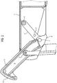
- Figure 2 shows the table extension plate 2 in an intermediate position, in which it has left the position of use, but has not yet reached the retracted position. It can be seen that the cam roller 3 has moved a distance along the guide track 4 in the direction of an end face 10 of the table extension plate 2.
- the lever 5 has performed a rotary movement about the axis 6, in which the axis 7 describes a segment of a circle, the radius of which is determined by the distance between the two axes.
- Figure 3 illustrates the table extension plate 2 in its retracted position, in which it is accommodated essentially below the table top 1.
- the coupling rod 6 extends transversely to a pull-out direction of the table extension plate 2 and that to control the movement of the table extension plate 2 between the use position and the retracted position, two identically acting gears are provided, which each have the components explained above, namely the cam roller 3, the guide track 4, the tab 8, the stop 9, the lever 5 and the axis 7 include.
- the coupling rod 6 is torsionally rigid, so that rotational movements of the respective levers of the gears are connected to one another and tilting of the table extension plate 2 during its transition from the position of use to the retracted position or vice versa is effectively prevented.
Landscapes
- Engineering & Computer Science (AREA)
- Mechanical Engineering (AREA)
- Aviation & Aerospace Engineering (AREA)
- Transportation (AREA)
- Passenger Equipment (AREA)
- Chair Legs, Seat Parts, And Backrests (AREA)
Abstract
Description
- Die Erfindung bezieht sich auf einen Fahrgasttisch mit einer ortsfesten Tischplatte und einer Tischauszugsplatte, die mittels zweier quer zu einer Auszugsrichtung voneinander beabstandeter Getriebe aus einer zurückgezogenen Position unterhalb der Tischplatte in eine Gebrauchsposition, bei der sich die Tischauszugsplatte an eine zugeordnete äußere Kante der Tischplatte anschließt, überführbar ist.
- Ein solcher Fahrgasttisch ist beispielsweise aus der
DE 10 2015 204 705 A1 bekannt. Fahrgasttische an Sitzgruppen von Schienenfahrzeugen sind häufig in ihrer festen Tiefe begrenzt, um genügend Raum für einen Zugang zu Fahrgastsitzen freizuhalten. Um dennoch eine nutzbare Tischfläche nahe an die Sitzposition heranführen zu können, wird die Tischauszugsplatte verwendet, die sich in ihrer Gebrauchsposition unmittelbar an die feste Tischplatte anschließt und somit insgesamt eine größere verfügbare Tischfläche bereitstellt. - Der Einsatz der zwei voneinander beabstandeten Getrieben, die sich typischerweise im seitlichen Bereich, der Tischauszugsplatte befinden, ermöglicht eine gute Aufnahme vertikaler Lasten. Die Bewegung der Tischauszugsplatte erfolgt typischerweise wenigstens abschnittsweise geradlinig oder in einem Wendepunkt. Dies hat zur Folge, dass nicht durchgehend eine Momentanpolachse im endlichen, senkrecht zur Bewegungsebene, vorhanden ist. Damit besteht die Möglichkeit, dass sich die Tischauszugsplatte undefiniert um eine Achse parallel zur vorgesehenen Bewegungsebene der Tischauszugsplatte verdrehen und dabei verkanten kann.
- Ausgehend hiervon liegt der Erfindung die Aufgabe zugrunde, bei dem eingangs genannten Fahrgasttisch ein Verkanten des Tischauszugsplatte bei deren Bewegung aus der zurückgezogenen Position in die Gebrauchsposition oder umgekehrt zu erschweren.
- Diese Aufgabe wird gelöst durch einen Fahrgasttisch mit den Merkmalen des Anspruchs 1.
- Dieser zeichnet sich gegenüber dem eingangs beschriebenen Fahrgasttisch dadurch aus, dass die zwei Getriebe jeweils mindestens einen Hebel umfassen, dessen eines Ende um eine erste Achse drehbar gegenüber der Tischplatte und dessen anderes Ende um eine zweite Achse drehbar gegenüber der Tischauszugsplatte gelagert ist, die zweite Achse bei einer Bewegung der Tischauszugsplatte von der Gebrauchsposition zu der zurückgezogenen Position oder umgekehrt eine kontinuierliche Drehbewegung entlang eines Kreissegments beschreibt, dessen Radius durch den Abstand der ersten Achse von der zweiten Achse bestimmt ist, und Rotationsbewegungen der jeweiligen Hebel der Getriebe über eine in Querrichtung der Auszugsrichtung der Tischauszugsplatte auf der ersten Achse verlaufende, torsionssteife Koppelstange miteinander verbunden sind.
- Die vorgesehene Kopplung der beiden Hebel mit Hilfe der torsionssteifen Koppelstange wirkt einem Verkanten der Tischauszugsplatte bei deren Bewegung wirksam entgegen. Folge ist es, dass keine Führungselemente für die Bewegung der Tischauszugsplatte erforderlich sind, welche Biegemomente zur Verhinderung des Verkantens der Tischauszugsplatte aufnehmen müssen. Damit lassen sich Führungselemente wesentlich einfacher gestalten, beispielsweise als offene Rollenführung.
- Bevorzugt ist jeweils das eine Ende des Hebels unmittelbar an der Tischplatte und das andere Ende des Hebels unmittelbar an der Tischauszugsplatte drehbar gelagert. Es ist jedoch hervorzuheben, dass die Vorgehensweise, eine torsionssteife Koppelstange vorzusehen und das andere Ende des Hebels eine Kreissegmentbewegung vornehmen zu lassen, auch auf jedwede Komponenten von Getrieben, die bei Fahrgasttischen vorgesehen sind, anwendbar ist.
- Vorteilhafterweise sind die durch die Koppelstange verbundenen Hebel direkt in die Getriebe der beiden Seiten integriert, in dem Sinn, dass sie den Freiheitsgrad auf genau eins, also die definierte Bewegung zwischen zurückgezogener Position und Gebrauchsposition, einstellen.
- Alternativ können auch die Getriebe unabhängig von den gekoppelten Hebeln bereits eine definierte Bewegung mit jeweils einem Freiheitsgrad herstellen, so dass die Hebel nur die Funktion haben, die Bewegungen der beiden Seiten zu synchronisieren.
- Vorteilhafterweise weisen die zwei Getriebe zur Führung der Tischauszugsplatte jeweils eine Kurvenrolle auf, die auf einer Führungsbahn abrollt. Dabei können die Führungsbahnen jeweils als in Seitenflächen der Tischauszugsplatte vorgesehene Nuten ausgebildet sein und die Kurvenrollen jeweils an der Tischplatte gelagert sein. Die damit realisierte Führung für die Tischauszugsplatte ist kostengünstig und fertigungstechnisch einfach umzusetzen.
- Der jeweilige Hebel kann derart unterhalb der Tischplatte angeordnet und gelagert sein, dass er bei Erreichen der Gebrauchsposition der Tischauszugsplatte rotatorisch bezüglich dieser festgelegt ist und so das Biegemoment des Überstandes über die Kurvenrolle aufnimmt.
Vorteilhafterweise ist die Kurvenrolle an der Tischplatte derart angeordnet und gelagert, dass sie in jeder bei einer Bewegung der Tischauszugsplatte aus der zurückgezogenen Position in die Gebrauchsposition eingenommenen Position der zweiten Drehachse von der zweiten Drehachse beabstandet ist. Durch diese Maßnahme wird eine Abstützbasis für die Tischauszugsplatte ermöglicht, welche die Tischauszugsplatte kontinuierlich in einer definierten Winkellage, d.h. mit nur einem resultierenden Freiheitsgrad, führt. - Ein Ausführungsbeispiel der Erfindung wird nachfolgend unter Bezugnahme auf die Zeichnung noch näher erläutert. Es zeigen:
- Figur 1
- eine schematische Querschnittsansicht einer Tischauszugsplatte in Kombination mit einer ortsfesten Tischplatte, wobei sich die Tischauszugsplatte in einer Gebrauchsposition befindet,
- Figur 2
- eine schematische Querschnittsansicht der Tischauszugsplatte von
Figur 1 in Kombination mit einer ortsfesten Tischplatte, wobei sich die Tischauszugsplatte in einer Zwischenposition befindet, - Figur 3
- eine schematische Querschnittsansicht der Tischauszugsplatte von
Figur 1 in Kombination mit einer ortsfesten Tischplatte, wobei sich die Tischauszugsplatte in einer zurückgezogenen Position befindet und - Figur 4
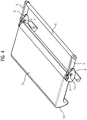
- eine perspektivische Ansicht auf die Tischauszugsplatte der
Figuren 1 bis 3 , mit zugehörigen Getrieben zum Anbau an eine ortsfeste Tischplatte. -
Figur 1 zeigt einen Fahrgasttisch beispielsweise zum Einsatz in einem Schienenfahrzeug. Der Fahrgasttisch umfasst eine in dem Fahrzeug fest montierte Tischplatte 1. Eine verfügbare Oberfläche des Fahrgasttisches kann mit Hilfe einer Tischauszugsplatte 2 vergrößert werden. InFigur 1 ist die relative Position der Tischauszugsplatte 2 in ihrer Gebrauchsstellung zu der Tischplatte 1 dargestellt. - An der Tischplatte 1 ist eine Kurvenrolle 3 drehbar gelagert, die in eine Führungsbahn 4 eingreift und entlang der Führungsbahn 4 abrollt, wenn die Tischauszugsplatte 2 beispielweise aus ihrer Gebrauchsposition in eine zurückgezogene Position unterhalb der Tischplatte 1 verbracht wird. Die Führungsbahn 4 ist als Nut ausgeführt, die in eine Seitenfläche der Tischauszugsplatte 2 eingebracht ist und im Wesentlichen linear verläuft, und zwar parallel zu einer Oberfläche der Tischauszugsplatte 2.
- Ein Hebel 5 ist mit seinem einen Ende um eine von einer Koppenstange 6 festgelegte erste Achse drehbar gegenüber der Tischplatte 1 gelagert. Das andere Ende des Hebels 5 ist über eine zweite Achse 7 drehbar an einer Lasche 8 gelagert, die mit der Tischauszugsplatte 2 fest verbunden und von dieser aus, bezogen auf die Tischplatte 1, einwärts gerichtet angeordnet ist.
- In der dargestellten Gebrauchsposition der Tischauszugsplatte 2 stößt die Lasche 8 gegen einen Anschlag 9, der in einem Abstand zu der Achse 7 an dem Hebel 5 vorgesehen ist. Insofern ist der Freiheitsgrad für eine Bewegung der Tischauszugsplatte 2 beschränkt.
-
Figur 2 zeigt die Tischauszugsplatte 2 in einer Zwischenposition, bei der sie die Gebrauchsposition verlassen, die zurückgezogene Position jedoch noch nicht erreicht hat. Ersichtlich hat sich die Kurvenrolle 3 eine Strecke entlang der Führungsbahn 4 in Richtung auf eine Stirnfläche 10 der Tischauszugspatte 2 bewegt. Der Hebel 5 hat eine Drehbewegung um die Achse 6 vollführt, bei der die Achse 7 ein Kreissegment beschreibt, dessen Radius durch den Abstand der beiden Achsen bestimmt ist. -
Figur 3 veranschaulicht die Tischauszugsplatte 2 in ihrer zurückgezogenen Position, bei der sie im Wesentlichen unterhalb der Tischplatte 1 untergebracht ist. Bei einem Übergang von der Position der Tischauszugsplatte 2 inFigur 2 zuFigur 3 wird die Kreisbewegung der zweiten Achse 7 weiter fortgesetzt. - Aus
Figur 4 wird ersichtlich, dass sich die Koppelstange 6 quer zu einer Auszugsrichtung der Tischauszugsplatte 2 erstreckt und dass zum Steuern der Bewegung der Tischauszugsplatte 2 zwischen der Gebrauchsposition und der zurückgezogenen Position zwei identisch wirkende Getriebe vorgesehen sind, welche jeweils die zuvor erläuterten Komponenten, nämlich die Kurvenrolle 3, die Führungsbahn 4, die Lasche 8, den Anschlag 9, den Hebel 5 und die Achse 7 umfassen. Es ist hervorzuheben, dass die Koppelstange 6 torsionssteif ausgebildet ist, so dass Rotationsbewegungen der jeweiligen Hebel der Getriebe miteinander verbunden sind und damit ein Verkanten der Tischauszugsplatte 2 bei ihrem Übergang aus der Gebrauchsposition in die zurückgezogene Position oder umgekehrt wirksam verhindert wird.
Claims (6)
- Fahrgasttisch mit einer ortsfesten Tischplatte (1) und einer Tischauszugsplatte (2), die mittels zweier quer zu einer Auszugsrichtung voneinander beabstandeter Getriebe aus einer zurückgezogenen Position unterhalb der Tischplatte (1) in eine Gebrauchsposition, bei der sich die Tischauszugsplatte (2) an eine zugeordnete äußere Kante der Tischplatte (1) anschließt, überführbar ist,
dadurch gekennzeichnet, dass
die zwei Getriebe jeweils mindestens einen Hebel (5) umfassen, dessen eines Ende um eine erste Achse drehbar gegenüber der Tischplatte (1) und dessen anderes Ende um eine zweite Achse (7) drehbar gegenüber der Tischauszugsplatte (2) gelagert ist,
die zweite Achse (7) bei einer Bewegung der Tischauszugsplatte (2) von der Gebrauchsposition zu der zurückgezogenen Position oder umgekehrt eine kontinuierliche Drehbewegung entlang eines Kreissegments beschreibt, dessen Radius durch den Abstand der ersten Achse von der zweiten Achse (7) bestimmt ist, und
Rotationsbewegungen der jeweiligen Hebel (5) der Getriebe über eine in Querrichtung der Auszugsrichtung der Tischauszugsplatte auf der ersten Achse verlaufende, torsionssteife Koppelstange (6) miteinander verbunden sind. - Fahrgasttisch nach Anspruch 1,
dadurch gekennzeichnet, dass
jeweils das eine Ende des Hebels (5) unmittelbar an der Tischplatte (1) und das andere Ende des Hebels (5) unmittelbar an der Tischauszugsplatte (2) drehbar gelagert ist. - Fahrgasttisch nach Anspruch 1 oder 2,
dadurch gekennzeichnet, dass
die zwei Getriebe zur Führung der Tischauszugsplatte (2) jeweils eine Kurvenrolle (3) aufweisen, die auf einer Führungsbahn (4) abrollt. - Fahrgasttisch nach Anspruche 3,
dadurch gekennzeichnet, dass
die Führungsbahnen (4) jeweils als in Seitenflächen der Tischauszugsplatte (2) vorgesehene Nuten ausgebildet sind und die Kurvenrollen (3) jeweils an der Tischplatte (1) gelagert sind. - Fahrgasttisch nach einem der Ansprüche 1 bis 4,
dadurch gekennzeichnet, dass
der jeweilige Hebel (5) derart unterhalb der Tischplatte (1) angeordnet und gelagert ist, dass er bei Erreichen der Gebrauchsposition der Tischauszugsplatte (2) festgelegt ist. - Fahrgasttisch nach einem der Ansprüche 1 bis 5,
dadurch gekennzeichnet, dass
die Kurvenrolle (3) an der Tischplatte (1) derart angeordnet und gelagert ist, dass sie in jeder bei einer Bewegung der Tischauszugsplatte (2) aus der zurückgezogenen Position in die Gebrauchsposition eingenommenen Position der zweiten Drehachse (7) von der zweiten Drehachse (7) beabstandet ist.
Applications Claiming Priority (1)
| Application Number | Priority Date | Filing Date | Title |
|---|---|---|---|
| DE102020204409.0A DE102020204409A1 (de) | 2020-04-06 | 2020-04-06 | Fahrgasttisch |
Publications (2)
| Publication Number | Publication Date |
|---|---|
| EP3892513A1 true EP3892513A1 (de) | 2021-10-13 |
| EP3892513B1 EP3892513B1 (de) | 2022-11-30 |
Family
ID=74859332
Family Applications (1)
| Application Number | Title | Priority Date | Filing Date |
|---|---|---|---|
| EP21161016.7A Active EP3892513B1 (de) | 2020-04-06 | 2021-03-05 | Fahrgasttisch |
Country Status (3)
| Country | Link |
|---|---|
| EP (1) | EP3892513B1 (de) |
| DE (1) | DE102020204409A1 (de) |
| ES (1) | ES2939495T3 (de) |
Cited By (1)
| Publication number | Priority date | Publication date | Assignee | Title |
|---|---|---|---|---|
| CN121084441A (zh) * | 2025-09-16 | 2025-12-09 | 沪强企业(盐城)有限公司 | 一种轨道交通用多功能小桌板 |
Citations (3)
| Publication number | Priority date | Publication date | Assignee | Title |
|---|---|---|---|---|
| SU1094785A1 (ru) * | 1983-02-14 | 1984-05-30 | Калининский Ордена Ленина Вагоностроительный Завод Им.М.И.Калинина | Приоконный столик железнодорожного вагона |
| DE9303108U1 (de) * | 1993-03-04 | 1993-04-22 | Geidobler, Manfred, 8091 Soyen | Freitragender Klapptisch zur Aufnahme von Funkbedienelementen und einer Schreibfläche zum Einbau in Feuerwehr- und Polizeifahrzeugen sowie allgemeinen Fahrzeugen |
| DE102015204705A1 (de) | 2015-03-16 | 2016-09-22 | Siemens Aktiengesellschaft | Verbreiterbarer Tisch |
Family Cites Families (1)
| Publication number | Priority date | Publication date | Assignee | Title |
|---|---|---|---|---|
| DE202017100035U1 (de) | 2017-01-06 | 2018-04-10 | Pöttker GmbH | Möbel mit Auszug |
-
2020
- 2020-04-06 DE DE102020204409.0A patent/DE102020204409A1/de not_active Ceased
-
2021
- 2021-03-05 EP EP21161016.7A patent/EP3892513B1/de active Active
- 2021-03-05 ES ES21161016T patent/ES2939495T3/es active Active
Patent Citations (3)
| Publication number | Priority date | Publication date | Assignee | Title |
|---|---|---|---|---|
| SU1094785A1 (ru) * | 1983-02-14 | 1984-05-30 | Калининский Ордена Ленина Вагоностроительный Завод Им.М.И.Калинина | Приоконный столик железнодорожного вагона |
| DE9303108U1 (de) * | 1993-03-04 | 1993-04-22 | Geidobler, Manfred, 8091 Soyen | Freitragender Klapptisch zur Aufnahme von Funkbedienelementen und einer Schreibfläche zum Einbau in Feuerwehr- und Polizeifahrzeugen sowie allgemeinen Fahrzeugen |
| DE102015204705A1 (de) | 2015-03-16 | 2016-09-22 | Siemens Aktiengesellschaft | Verbreiterbarer Tisch |
Cited By (1)
| Publication number | Priority date | Publication date | Assignee | Title |
|---|---|---|---|---|
| CN121084441A (zh) * | 2025-09-16 | 2025-12-09 | 沪强企业(盐城)有限公司 | 一种轨道交通用多功能小桌板 |
Also Published As
| Publication number | Publication date |
|---|---|
| EP3892513B1 (de) | 2022-11-30 |
| DE102020204409A1 (de) | 2021-10-07 |
| ES2939495T3 (es) | 2023-04-24 |
Similar Documents
| Publication | Publication Date | Title |
|---|---|---|
| DE69411251T2 (de) | Gleitstück mit einstellbarer Laufbahnpositionierung | |
| EP1314626A1 (de) | Schwenkschiebetür für Fahrzeuge, insbesondere Fahrgasttür für Fahrzeuge des öffentlichen Personennahverkehrs | |
| DE3909292A1 (de) | Laengs- und quer-tischfuehrungs- und -drehmechanismus | |
| WO2015113908A1 (de) | Verstellsystem für einen sitz sowie sitz | |
| DE2844647C2 (de) | Längsverstellvorrichtung für einen Fahrzeugsitz, insbesondere einen Kraftfahrzeugsitz | |
| DE202016101698U1 (de) | Gleitlager, Gleitführung und Gleitelement für eine Kurvenschiene | |
| EP3214326B1 (de) | Lineares gleitlager mit kleinem winkelfehler | |
| DE10253401A1 (de) | Schiebedachsystem für ein Kraftfahrzeug | |
| EP3892513B1 (de) | Fahrgasttisch | |
| DE2659010C3 (de) | Weiche für ein Zweischienengleis für Magnetschwebefahrzeuge | |
| DE102013226826A1 (de) | Linearmotoranordnung und Werkzeugmaschine mit einer Linearmotoranordnung | |
| EP1980359B1 (de) | Verstelleinheit | |
| DE3013410A1 (de) | Fuehrungssystem fuer lineare bewegungen | |
| DE102017213361B4 (de) | Wälzfräsmaschine, umfassend einen Wälzfrässchlitten und einen Anfasschlitten auf einem gemeinsamen Schienensystem | |
| EP0802130A1 (de) | Transportsystem | |
| WO2018068778A1 (de) | Getriebe sowie kopfstütze mit wenigstens einem elektrischen antrieb, umfassend ein getriebe | |
| DE102010032507B4 (de) | Lineareinsteller für einen Fahrzeugsitz | |
| EP3892494B1 (de) | Fahrgasttisch | |
| EP4499536A1 (de) | Transportsystem | |
| DE19737034B4 (de) | Lenkmodul eines Kraftfahrzeugs mit sowohl in ihrer Neigung als auch in der Länge verstellbarer Lenksäule | |
| EP0788767A1 (de) | Röntgendiagnostikgerät | |
| EP3074649B1 (de) | Abstandshalter für eine gleitführung und hubsäule | |
| EP0923904B1 (de) | Vorrichtung zum Bewegen eines Röntgentischs oder dgl. | |
| EP1663564A1 (de) | Schweisszange | |
| DE102013012660A1 (de) | Verzahnungsmaschine und Verfahren zum Bearbeiten einer Verzahnung |
Legal Events
| Date | Code | Title | Description |
|---|---|---|---|
| PUAI | Public reference made under article 153(3) epc to a published international application that has entered the european phase |
Free format text: ORIGINAL CODE: 0009012 |
|
| STAA | Information on the status of an ep patent application or granted ep patent |
Free format text: STATUS: THE APPLICATION HAS BEEN PUBLISHED |
|
| AK | Designated contracting states |
Kind code of ref document: A1 Designated state(s): AL AT BE BG CH CY CZ DE DK EE ES FI FR GB GR HR HU IE IS IT LI LT LU LV MC MK MT NL NO PL PT RO RS SE SI SK SM TR |
|
| STAA | Information on the status of an ep patent application or granted ep patent |
Free format text: STATUS: REQUEST FOR EXAMINATION WAS MADE |
|
| 17P | Request for examination filed |
Effective date: 20220318 |
|
| RBV | Designated contracting states (corrected) |
Designated state(s): AL AT BE BG CH CY CZ DE DK EE ES FI FR GB GR HR HU IE IS IT LI LT LU LV MC MK MT NL NO PL PT RO RS SE SI SK SM TR |
|
| GRAP | Despatch of communication of intention to grant a patent |
Free format text: ORIGINAL CODE: EPIDOSNIGR1 |
|
| STAA | Information on the status of an ep patent application or granted ep patent |
Free format text: STATUS: GRANT OF PATENT IS INTENDED |
|
| INTG | Intention to grant announced |
Effective date: 20220804 |
|
| GRAS | Grant fee paid |
Free format text: ORIGINAL CODE: EPIDOSNIGR3 |
|
| GRAA | (expected) grant |
Free format text: ORIGINAL CODE: 0009210 |
|
| STAA | Information on the status of an ep patent application or granted ep patent |
Free format text: STATUS: THE PATENT HAS BEEN GRANTED |
|
| AK | Designated contracting states |
Kind code of ref document: B1 Designated state(s): AL AT BE BG CH CY CZ DE DK EE ES FI FR GB GR HR HU IE IS IT LI LT LU LV MC MK MT NL NO PL PT RO RS SE SI SK SM TR |
|
| REG | Reference to a national code |
Ref country code: CH Ref legal event code: EP Ref country code: GB Ref legal event code: FG4D Free format text: NOT ENGLISH |
|
| REG | Reference to a national code |
Ref country code: AT Ref legal event code: REF Ref document number: 1534470 Country of ref document: AT Kind code of ref document: T Effective date: 20221215 Ref country code: DE Ref legal event code: R096 Ref document number: 502021000278 Country of ref document: DE |
|
| REG | Reference to a national code |
Ref country code: IE Ref legal event code: FG4D Free format text: LANGUAGE OF EP DOCUMENT: GERMAN |
|
| REG | Reference to a national code |
Ref country code: LT Ref legal event code: MG9D |
|
| REG | Reference to a national code |
Ref country code: NL Ref legal event code: MP Effective date: 20221130 |
|
| REG | Reference to a national code |
Ref country code: ES Ref legal event code: FG2A Ref document number: 2939495 Country of ref document: ES Kind code of ref document: T3 Effective date: 20230424 |
|
| PG25 | Lapsed in a contracting state [announced via postgrant information from national office to epo] |
Ref country code: SE Free format text: LAPSE BECAUSE OF FAILURE TO SUBMIT A TRANSLATION OF THE DESCRIPTION OR TO PAY THE FEE WITHIN THE PRESCRIBED TIME-LIMIT Effective date: 20221130 Ref country code: PT Free format text: LAPSE BECAUSE OF FAILURE TO SUBMIT A TRANSLATION OF THE DESCRIPTION OR TO PAY THE FEE WITHIN THE PRESCRIBED TIME-LIMIT Effective date: 20230331 Ref country code: NO Free format text: LAPSE BECAUSE OF FAILURE TO SUBMIT A TRANSLATION OF THE DESCRIPTION OR TO PAY THE FEE WITHIN THE PRESCRIBED TIME-LIMIT Effective date: 20230228 Ref country code: LT Free format text: LAPSE BECAUSE OF FAILURE TO SUBMIT A TRANSLATION OF THE DESCRIPTION OR TO PAY THE FEE WITHIN THE PRESCRIBED TIME-LIMIT Effective date: 20221130 Ref country code: FI Free format text: LAPSE BECAUSE OF FAILURE TO SUBMIT A TRANSLATION OF THE DESCRIPTION OR TO PAY THE FEE WITHIN THE PRESCRIBED TIME-LIMIT Effective date: 20221130 |
|
| PG25 | Lapsed in a contracting state [announced via postgrant information from national office to epo] |
Ref country code: RS Free format text: LAPSE BECAUSE OF FAILURE TO SUBMIT A TRANSLATION OF THE DESCRIPTION OR TO PAY THE FEE WITHIN THE PRESCRIBED TIME-LIMIT Effective date: 20221130 Ref country code: PL Free format text: LAPSE BECAUSE OF FAILURE TO SUBMIT A TRANSLATION OF THE DESCRIPTION OR TO PAY THE FEE WITHIN THE PRESCRIBED TIME-LIMIT Effective date: 20221130 Ref country code: LV Free format text: LAPSE BECAUSE OF FAILURE TO SUBMIT A TRANSLATION OF THE DESCRIPTION OR TO PAY THE FEE WITHIN THE PRESCRIBED TIME-LIMIT Effective date: 20221130 Ref country code: IS Free format text: LAPSE BECAUSE OF FAILURE TO SUBMIT A TRANSLATION OF THE DESCRIPTION OR TO PAY THE FEE WITHIN THE PRESCRIBED TIME-LIMIT Effective date: 20230330 Ref country code: HR Free format text: LAPSE BECAUSE OF FAILURE TO SUBMIT A TRANSLATION OF THE DESCRIPTION OR TO PAY THE FEE WITHIN THE PRESCRIBED TIME-LIMIT Effective date: 20221130 Ref country code: GR Free format text: LAPSE BECAUSE OF FAILURE TO SUBMIT A TRANSLATION OF THE DESCRIPTION OR TO PAY THE FEE WITHIN THE PRESCRIBED TIME-LIMIT Effective date: 20230301 |
|
| PG25 | Lapsed in a contracting state [announced via postgrant information from national office to epo] |
Ref country code: NL Free format text: LAPSE BECAUSE OF FAILURE TO SUBMIT A TRANSLATION OF THE DESCRIPTION OR TO PAY THE FEE WITHIN THE PRESCRIBED TIME-LIMIT Effective date: 20221130 |
|
| PG25 | Lapsed in a contracting state [announced via postgrant information from national office to epo] |
Ref country code: SM Free format text: LAPSE BECAUSE OF FAILURE TO SUBMIT A TRANSLATION OF THE DESCRIPTION OR TO PAY THE FEE WITHIN THE PRESCRIBED TIME-LIMIT Effective date: 20221130 Ref country code: RO Free format text: LAPSE BECAUSE OF FAILURE TO SUBMIT A TRANSLATION OF THE DESCRIPTION OR TO PAY THE FEE WITHIN THE PRESCRIBED TIME-LIMIT Effective date: 20221130 Ref country code: EE Free format text: LAPSE BECAUSE OF FAILURE TO SUBMIT A TRANSLATION OF THE DESCRIPTION OR TO PAY THE FEE WITHIN THE PRESCRIBED TIME-LIMIT Effective date: 20221130 Ref country code: DK Free format text: LAPSE BECAUSE OF FAILURE TO SUBMIT A TRANSLATION OF THE DESCRIPTION OR TO PAY THE FEE WITHIN THE PRESCRIBED TIME-LIMIT Effective date: 20221130 Ref country code: CZ Free format text: LAPSE BECAUSE OF FAILURE TO SUBMIT A TRANSLATION OF THE DESCRIPTION OR TO PAY THE FEE WITHIN THE PRESCRIBED TIME-LIMIT Effective date: 20221130 |
|
| PGFP | Annual fee paid to national office [announced via postgrant information from national office to epo] |
Ref country code: ES Payment date: 20230621 Year of fee payment: 3 Ref country code: DE Payment date: 20230519 Year of fee payment: 3 |
|
| PG25 | Lapsed in a contracting state [announced via postgrant information from national office to epo] |
Ref country code: SK Free format text: LAPSE BECAUSE OF FAILURE TO SUBMIT A TRANSLATION OF THE DESCRIPTION OR TO PAY THE FEE WITHIN THE PRESCRIBED TIME-LIMIT Effective date: 20221130 Ref country code: AL Free format text: LAPSE BECAUSE OF FAILURE TO SUBMIT A TRANSLATION OF THE DESCRIPTION OR TO PAY THE FEE WITHIN THE PRESCRIBED TIME-LIMIT Effective date: 20221130 |
|
| REG | Reference to a national code |
Ref country code: DE Ref legal event code: R097 Ref document number: 502021000278 Country of ref document: DE |
|
| PLBE | No opposition filed within time limit |
Free format text: ORIGINAL CODE: 0009261 |
|
| STAA | Information on the status of an ep patent application or granted ep patent |
Free format text: STATUS: NO OPPOSITION FILED WITHIN TIME LIMIT |
|
| PG25 | Lapsed in a contracting state [announced via postgrant information from national office to epo] |
Ref country code: MC Free format text: LAPSE BECAUSE OF FAILURE TO SUBMIT A TRANSLATION OF THE DESCRIPTION OR TO PAY THE FEE WITHIN THE PRESCRIBED TIME-LIMIT Effective date: 20221130 |
|
| 26N | No opposition filed |
Effective date: 20230831 |
|
| PG25 | Lapsed in a contracting state [announced via postgrant information from national office to epo] |
Ref country code: SI Free format text: LAPSE BECAUSE OF FAILURE TO SUBMIT A TRANSLATION OF THE DESCRIPTION OR TO PAY THE FEE WITHIN THE PRESCRIBED TIME-LIMIT Effective date: 20221130 |
|
| REG | Reference to a national code |
Ref country code: BE Ref legal event code: MM Effective date: 20230331 |
|
| PG25 | Lapsed in a contracting state [announced via postgrant information from national office to epo] |
Ref country code: LU Free format text: LAPSE BECAUSE OF NON-PAYMENT OF DUE FEES Effective date: 20230305 |
|
| REG | Reference to a national code |
Ref country code: IE Ref legal event code: MM4A |
|
| PG25 | Lapsed in a contracting state [announced via postgrant information from national office to epo] |
Ref country code: IE Free format text: LAPSE BECAUSE OF NON-PAYMENT OF DUE FEES Effective date: 20230305 |
|
| PG25 | Lapsed in a contracting state [announced via postgrant information from national office to epo] |
Ref country code: BE Free format text: LAPSE BECAUSE OF NON-PAYMENT OF DUE FEES Effective date: 20230331 |
|
| PGFP | Annual fee paid to national office [announced via postgrant information from national office to epo] |
Ref country code: FR Payment date: 20240319 Year of fee payment: 4 |
|
| PGFP | Annual fee paid to national office [announced via postgrant information from national office to epo] |
Ref country code: IT Payment date: 20240401 Year of fee payment: 4 |
|
| REG | Reference to a national code |
Ref country code: DE Ref legal event code: R119 Ref document number: 502021000278 Country of ref document: DE |
|
| REG | Reference to a national code |
Ref country code: CH Ref legal event code: PL |
|
| PG25 | Lapsed in a contracting state [announced via postgrant information from national office to epo] |
Ref country code: BG Free format text: LAPSE BECAUSE OF FAILURE TO SUBMIT A TRANSLATION OF THE DESCRIPTION OR TO PAY THE FEE WITHIN THE PRESCRIBED TIME-LIMIT Effective date: 20221130 |
|
| PG25 | Lapsed in a contracting state [announced via postgrant information from national office to epo] |
Ref country code: BG Free format text: LAPSE BECAUSE OF FAILURE TO SUBMIT A TRANSLATION OF THE DESCRIPTION OR TO PAY THE FEE WITHIN THE PRESCRIBED TIME-LIMIT Effective date: 20221130 |
|
| PG25 | Lapsed in a contracting state [announced via postgrant information from national office to epo] |
Ref country code: DE Free format text: LAPSE BECAUSE OF NON-PAYMENT OF DUE FEES Effective date: 20241001 |
|
| PG25 | Lapsed in a contracting state [announced via postgrant information from national office to epo] |
Ref country code: DE Free format text: LAPSE BECAUSE OF NON-PAYMENT OF DUE FEES Effective date: 20241001 Ref country code: CH Free format text: LAPSE BECAUSE OF NON-PAYMENT OF DUE FEES Effective date: 20240331 |
|
| PGFP | Annual fee paid to national office [announced via postgrant information from national office to epo] |
Ref country code: AT Payment date: 20250417 Year of fee payment: 5 |
|
| REG | Reference to a national code |
Ref country code: ES Ref legal event code: FD2A Effective date: 20250425 |
|
| PG25 | Lapsed in a contracting state [announced via postgrant information from national office to epo] |
Ref country code: ES Free format text: LAPSE BECAUSE OF NON-PAYMENT OF DUE FEES Effective date: 20240306 |
|
| PG25 | Lapsed in a contracting state [announced via postgrant information from national office to epo] |
Ref country code: CY Free format text: LAPSE BECAUSE OF FAILURE TO SUBMIT A TRANSLATION OF THE DESCRIPTION OR TO PAY THE FEE WITHIN THE PRESCRIBED TIME-LIMIT; INVALID AB INITIO Effective date: 20210305 |
|
| PG25 | Lapsed in a contracting state [announced via postgrant information from national office to epo] |
Ref country code: HU Free format text: LAPSE BECAUSE OF FAILURE TO SUBMIT A TRANSLATION OF THE DESCRIPTION OR TO PAY THE FEE WITHIN THE PRESCRIBED TIME-LIMIT; INVALID AB INITIO Effective date: 20210305 |
|
| GBPC | Gb: european patent ceased through non-payment of renewal fee |
Effective date: 20250305 |
|
| PG25 | Lapsed in a contracting state [announced via postgrant information from national office to epo] |
Ref country code: TR Free format text: LAPSE BECAUSE OF FAILURE TO SUBMIT A TRANSLATION OF THE DESCRIPTION OR TO PAY THE FEE WITHIN THE PRESCRIBED TIME-LIMIT Effective date: 20221130 |
|
| PG25 | Lapsed in a contracting state [announced via postgrant information from national office to epo] |
Ref country code: GB Free format text: LAPSE BECAUSE OF NON-PAYMENT OF DUE FEES Effective date: 20250305 |
|
| PG25 | Lapsed in a contracting state [announced via postgrant information from national office to epo] |
Ref country code: IT Free format text: LAPSE BECAUSE OF NON-PAYMENT OF DUE FEES Effective date: 20250305 Ref country code: FR Free format text: LAPSE BECAUSE OF NON-PAYMENT OF DUE FEES Effective date: 20250331 |