EP3892149A1 - Slide fastener, method for manufacturing stop, and mold device - Google Patents
Slide fastener, method for manufacturing stop, and mold device Download PDFInfo
- Publication number
- EP3892149A1 EP3892149A1 EP18942308.0A EP18942308A EP3892149A1 EP 3892149 A1 EP3892149 A1 EP 3892149A1 EP 18942308 A EP18942308 A EP 18942308A EP 3892149 A1 EP3892149 A1 EP 3892149A1
- Authority
- EP
- European Patent Office
- Prior art keywords
- fastener
- stop member
- stop
- thinned portion
- fastener elements
- Prior art date
- Legal status (The legal status is an assumption and is not a legal conclusion. Google has not performed a legal analysis and makes no representation as to the accuracy of the status listed.)
- Granted
Links
Images




Classifications
-
- A—HUMAN NECESSITIES
- A44—HABERDASHERY; JEWELLERY
- A44B—BUTTONS, PINS, BUCKLES, SLIDE FASTENERS, OR THE LIKE
- A44B19/00—Slide fasteners
- A44B19/02—Slide fasteners with a series of separate interlocking members secured to each stringer tape
- A44B19/04—Stringers arranged edge-to-edge when fastened, e.g. abutting stringers
- A44B19/06—Stringers arranged edge-to-edge when fastened, e.g. abutting stringers with substantially rectangular members having interlocking projections and pieces
-
- A—HUMAN NECESSITIES
- A44—HABERDASHERY; JEWELLERY
- A44B—BUTTONS, PINS, BUCKLES, SLIDE FASTENERS, OR THE LIKE
- A44B19/00—Slide fasteners
- A44B19/24—Details
- A44B19/26—Sliders
-
- A—HUMAN NECESSITIES
- A44—HABERDASHERY; JEWELLERY
- A44B—BUTTONS, PINS, BUCKLES, SLIDE FASTENERS, OR THE LIKE
- A44B19/00—Slide fasteners
- A44B19/24—Details
- A44B19/36—Means for permanently uniting the stringers at the end; Means for stopping movement of slider at the end
-
- A—HUMAN NECESSITIES
- A44—HABERDASHERY; JEWELLERY
- A44B—BUTTONS, PINS, BUCKLES, SLIDE FASTENERS, OR THE LIKE
- A44B19/00—Slide fasteners
- A44B19/24—Details
- A44B19/38—Means at the end of stringer by which the slider can be freed from one stringer, e.g. stringers can be completely separated from each other
-
- A—HUMAN NECESSITIES
- A44—HABERDASHERY; JEWELLERY
- A44B—BUTTONS, PINS, BUCKLES, SLIDE FASTENERS, OR THE LIKE
- A44B19/00—Slide fasteners
- A44B19/42—Making by processes not fully provided for in one other class, e.g. B21D53/50, B21F45/18, B22D17/16, B29D5/00
- A44B19/60—Applying end stops upon stringer tapes
Definitions
- the present disclosure is related to a slide fastener, a method of producing stop member and a mold device.
- Patent literature 1 discloses that a coiled fastener element of a helically wound mono-filament is partially melt and coupled by a laser light, thereby forming a stop member.
- Patent literature 2 discloses that fastener elements are melted and coupled by ultrasonic waves to form a stop member.
- Slide fastener may include: a pair of fastener stringers each of which includes a fastener tape and a series of fastener elements arranged with interspaces along a side-edge of the fastener tape; at least one slider for opening and closing the pair of fastener stringers; and a stop member attached to the side-edges of the fastener tapes at a position adjacent to the series of fastener elements, wherein at least one of the following conditions (i)-(iii) are satisfied:
- the stop member has a thick portion at least partially enclosing the thinned portion or the through-hole.
- the thick portion includes or configures an outer peripheral wall of the stop member.
- the stop member includes a quasi-element portion partially shaped like (resembling) the fastener element.
- the quasi-element portion has a groove that extends in a front-rear direction that is a same direction as a movement direction of the slider.
- the quasi-element portion includes a portion shaped like a front-half of the fastener element provided that the fastener element is partitioned into front and rear halves arranged along a front-rear direction that is a same direction as a movement direction of the slider.
- a method of producing a stop member for a slide fastener including: providing adjacently-arranged two or more fastener elements of a plurality of fastener elements between upper and lower molds, said plurality of fastener elements being arranged with interspaces along a side-edge of a fastener tape in at least one fastener stringer; softening or melting said two or more fastener elements provided between the upper and lower molds by heat transmitted from the upper mold and/or the lower mold; and cooling softened or melted material inside a cavity defined by the upper and lower molds to obtain a stop member shaped in accordance with the cavity.
- the cavity is shaped to form at least one thinned portion and/or at least one through-hole at the two or more fastener elements. Interspace between the fastener elements would be filled by the softened or melted material.
- a mold device for producing a stop member of a slide fastener may include: upper and lower molds to form a cavity configured to reshape adjacently-arranged two or more fastener elements of a plurality of fastener elements arranged with interspaces along a side-edge of a fastener tape in at least one fastener stringer, wherein said cavity is shaped to form at least one thinned portion and/or at least one through-hole at said two or more fastener elements and to fill the interspace between the two or more fastener elements with softened or melted material thereof.
- the fastener elements arranged with interspaces along the side-edge of fastener tape can be used to form a stop member.
- Fig. 1 is a schematic elevational view of a slide fastener 1, illustrating an upper surface of the slide fastener 1.
- Fig. 2 is a schematic perspective view of a rear stop 6 included in a slide fastener 1. Illustration of left and right fastener tapes 3 is omitted.
- Fig. 3 is a schematic upper view of a rear stop 6 included in a slide fastener 1. Illustration of left and right fastener tapes 3 is omitted.
- Fig. 4 is a schematic cross-sectional view of a rear stop 6 taken along a dashed line IV-IV in Fig. 3 .
- Fig. 5 is a view schematically illustrating sides of a rear stop 6 and an adjacent fastener element 4, and illustrating a partial cross-section of the rear stop 6.
- Fig. 6 is a schematic perspective view of a front stop 7 included in a slide fastener 1. Illustration of left and right fastener tapes 3 is omitted.
- Fig. 7 is a schematic upper view of a front stop 7 included in a slide fastener 1. Illustration of left and right fastener tapes 3 is omitted.
- Fig. 8 is a schematic cross-sectional view of a front stop 7 taken along a dashed line VIII-VIII in Fig. 7 .
- Fig. 9 is a view schematically illustrating a side of a front stop 7.
- Fig. 10 is a view illustrating that a rear stop 6 is formed based on remolding of fastener elements 4.
- Fig. 10 is a schematic perspective view of a front stop 7 included in a slide fastener 1. Illustration of left and right fastener tapes 3 is omitted.
- Fig. 8 is a schematic cross-sectional view of a front stop 7 taken along a dashed line VIII
- FIG. 11 is a view illustrating that a front stop 7 is formed based on remolding of fastener elements 4.
- Fig. 12 is a schematic elevational view of a fastener chain where a space portion is formed.
- Fig. 13 is a view illustrating that fastener elements 4 of a respective fastener stringer 2 of a fastener chain 8 are sandwiched between upper and lower molds of a mold device 9.
- Fig. 14 is a view illustrating that left and right fastener elements 4 of a fastener chain 8 are sandwiched between upper and lower molds of a mold device 9.
- Fig. 15 is a schematic view of a mold device 9.
- Fig. 12 is a schematic elevational view of a fastener chain where a space portion is formed.
- Fig. 13 is a view illustrating that fastener elements 4 of a respective fastener stringer 2 of a fastener chain 8 are sandwiched between upper and lower molds of a mold device 9.
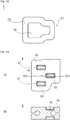
- FIG. 16 is a schematic upper view of a rear stop 6 of an embodiment in which a thinned portion 61 and a through-hole 68 are formed in a rear stop 6.
- Fig. 17 is a schematic cross-sectional view of a rear stop 6 taken along a dashed line X17-X17 in Fig. 16 .
- Fig. 18 is a schematic upper view of a rear stop 6 of an embodiment in which a through-hole 68 is formed in a rear stop 6.
- Fig. 19 is a schematic cross-sectional view of a rear stop 6 taken along a dashed line X19-X19 in Fig. 18 .
- Fig. 20 is a schematic upper view of another embodiment of rear stop 6.
- Fig. 17 is a schematic cross-sectional view of a rear stop 6 taken along a dashed line X17-X17 in Fig. 16 .
- Fig. 18 is a schematic upper view of a rear stop 6 of an embodiment in which a through
- FIG. 21 is a schematic upper view of another embodiment of front stop 7.
- Fig. 22 is a schematic upper view of another embodiment of front stop 7.
- Fig. 23 is a schematic upper view of another embodiment of rear stop 6, (a) illustrating an upper view and (b) illustrating a cross-section taken along a dashed line X23-X23 in (a).
- Fig. 24 is a schematic upper view of another embodiment of rear stop 6, (a) illustrating an upper view and (b) illustrating a cross-section taken along a dashed line X24-X24 in (a).
- FIG. 25 is a schematic upper view of another embodiment of rear stop 6, (a) illustrating an upper view and (b) illustrating a cross-section taken along a dashed line X25-X25 in (a).
- Fig. 26 is a schematic view of another embodiment of front stop 7, (a) illustrating an upper view and (b) illustrating a cross-section taken along a dashed line X26-X26 in (a).
- Fig. 27 is a schematic view of another embodiment of front stop 7, (a) illustrating an upper view and (b) illustrating a cross-section taken along a dashed line X27-X27 in (a).
- a slide fastener 1 has a pair of left and right fastener stringers 2 and at least one slider 5 for opening and closing the pair of left and right fastener stringers 2.
- Each fastener stringer 2 includes a fastener tape 3 and a series of fastener elements 4.
- the series of fastener elements 4 includes fastener elements 4 arranged with interspaces 49 along a side-edge 32 of the fastener tape 3.
- the fastener element 4 is a resin-made fastener element. Note that other types of embodiments different from the slide fastener 1 shown in Fig. 1 (e.g. a concealed slide fastener) could be conceived.
- front-rear direction would be understood based on movement direction of the slider 5, particularly for the slide fastener 1.
- the left-right direction would be understood with reference to the pair of fastener stringers 2 to be opened and closed by the slider 5.
- Up-down direction is orthogonal to the front-rear and the left-right directions. Note that these direction can be redefined in view of other parts of description in the present specification.
- the fastener tape 3 is typically a woven fabric or knitted fabric or mixture thereof and has flexibility.
- the fastener tape 3 has a tape main portion 31 and a side-edge 32, both extending in the front-rear direction.
- the side-edge 32 is provided with a core thread, enhancing attachment strength of the fastener elements 4 to the fastener tape 3.
- the fastener element 4 has a base portion 41 attached to the side-edge 32 of the fastener tape 3, i.e. to the core thread, and a neck 42 connected to the base portion 41, and a head 43 connected to the base portion 41 via the neck 42.
- the neck 42 and the head 43 are arranged outward of the fastener tape 3.
- the fastener element 4 has projections 44 arranged to sandwich the neck 42.
- the terminal surface of the head 43 is provided with a groove 45 to avoid interference with a projection 44 of a fastener element 4 to be engaged with (See Fig. 5 ).
- the fastener element can have various shapes other than the presently disclosed one. In some cases, the head 43 of the fastener element 4 is not provided with the groove 45.
- the fastener element 4 may be produced through inset-molding wherein a fastener tape 3 is arranged in a cavity of a mold device of an injection molding apparatus and melted resin is supplied into the cavity of the mold device.
- a fastener tape 3 is arranged in a cavity of a mold device of an injection molding apparatus and melted resin is supplied into the cavity of the mold device.
- the fastener elements 4 are attached to the fastener tape 3 through other ways (e.g. through swaging). Note that embodiments are also envisioned without difficulty where the fastener elements 4 are shaped differently from those shown in Figs. 1 and 5 .
- Slider 5 may be appropriately configured in accordance with a type of slide fastener 1.
- the slider 5 has an upper wing, a lower wing, and a column connecting the upper and lower wings, front mouths are provided at left and right sides of the column and a rear mouth is provided at the opposite side of the left and right front mouths.
- Y-shaped element passage is formed in the slider 5.
- the slide fastener 1 has a stop member attached to the side-edge(s) 32 of the fastener tape(s) 3 at a position adjacent to the series of fastener elements 4.
- the stop member is provided to prevent forward or rearward movement of the slider 5.
- the stop member is made of a same material as the fastener elements 4 (e.g. thermoplastic resin) and has a same color as the fastener elements 4.
- a color of the stop member may be the first color or the second color or a mixed color of the first and second colors.
- the stop member is one rear stop 6 or one or two front stops 7 or combination of these stops.
- embodiments are envisaged where the rear stop is formed in the same manner as the illustrated two front stops 7. Additionally or alternatively, embodiments are envisioned where the front stop is formed in the same manner as the illustrated one rear stops 6.
- the rear stop 6 is attached to the side-edges 32 of the left and right fastener tapes 3 at a position adjacent to the rear end of the engaged left and right series of fastener elements 4.
- Left front stop 7 is attached to the side-edge 32 of the left fastener tape 3 at a position adjacent to the front end of the left series of fastener elements 4.
- the rear stop 6 may have a front edge which can enter into the slider 5.
- the front edge of the rear stop 6 collides with the column of the slider 5, thereby preventing the slider 6 from moving rearward.
- the rear stop 6 may have a portion which cannot enter into the slider 5.
- the front edge of the rear stop 6 is provided with a boss 69 projecting in the left-right direction, preventing the front edge of the rear stop 6 from entering into the slider 5.
- the slider 5 collides with the boss 69 of the rear stop 6 and thus the rearward movement of the slider 5 is prevented.
- the entirety of the front stop 7 may enter into the slider 5.
- Left and right front stops 7 collide with each other at an intermediate position between the column and the rear mouth in the slider 5, thus preventing the slider 5 from moving forward.
- the front stop 7 may have a portion which cannot enter into the slider 5.
- the front edge of the front stop 7 is provided with a boss 79 projecting in the left-right direction, and thus preventing the front edge of the front stop 7 from entering into the slider 5.
- the slide 5 collides with the boss 79 of the front stop 7 and thus the Forward movement of the slider 5 is prevented.
- the stop member such as the rear stop 6 and the front stop 7 is not formed by newly supplying melted resin into a cavity of a mold device.
- the stop member is formed by remolding the fastener element(s) 4. Material of stop member is firstly shaped as fastener element 4 and then shaped as stop member. Seemingly, this may increase complexity of production of stop members.
- the present inventors have newly discovered that the formation of stop member based on remolding of the fastener element 4 allows reduced burden of determining and controlling a color of stop member in relation to a color of fastener elements 4.
- the stop member is formed from the fastener element(s) 4, the stop member is made of the same material as the fastener elements 4 (e.g. thermoplastic resin) and have the same color as the fastener elements 4. Accordingly, the burden of preparing material having the same color (e.g. red, blue, or green) as the fastener element 4 in order to produce a stop member would be avoided or reduced. For example, the burden of preparing, in one hand, red color resin in order to produce a stop member having the same color as the red color fastener element and, in the other hand, blue color resin in order to produce a stop member having the same color as the blue color fastener element would be avoided or reduced.
- red color resin in order to produce a stop member having the same color as the red color fastener element and, in the other hand, blue color resin in order to produce a stop member having the same color as the blue color fastener element would be avoided or reduced.
- stop member In a case where an injection molding apparatus for stop members is commonly used for producing the stop members having different colors, changing a color of stop member would require, in general, additional task(s) at the injection molding apparatus (such as washing out the remaining resin material in the flow channel of the injection molding apparatus at the previous cycle).
- additional task(s) at the injection molding apparatus such as washing out the remaining resin material in the flow channel of the injection molding apparatus at the previous cycle.
- the stop member is formed based on remolding of the fastener element(s) 4, such burden would be avoided or reduced in terms of forming stop members.
- Formation of stop member based on remolding of fastener element(s) 4 may be indicated by one of the following conditions.
- the rear stop 6 may be formed by remolding the left and right engaged fastener elements 4 (See Fig. 10 ).
- the front stop 7 may be formed by remolding the fastener elements 4 adjacently arranged along the side-edge 32 of the fastener tape 3 (See Fig. 11 ).
- the front stop 7 may be formed by remolding one fastener element 4 at the side-edge 32 of the fastener tape 3 (See Fig. 22 ).
- dotted lines illustrate fastener elements 4 (or a portion thereof) which are a source of material for stop member.
- the rear stop 6 and the front stop 7 have at least one thinned portion 61,71 having a thickness less than a thickness of the fastener element 4 (e.g. see Figs. 2-11 ) and/or at least one through-hole 68 extending through the stop member 6,7 in the up-down direction (e.g. see Figs. 16-19 ) as shown in Figs. 10 and 11 .
- This ensures a certain amount of material be extruded out of the original contour of the fastener element 4, the interspace 49 between the fastener elements 4 be filled and the fastener elements 4 be combined into one stop member.
- the thinned portion 61,71 and/or the through-hole 68 at the stop member is configured to allow the stop member 6,7 to be produced by remolding of one fastener element 4 or two or more fastener elements 4.
- the thinned portion 61,71 and/or the through-hole 68 is configured to allow that two or more fastener elements 4 to be combined one another.
- " remolding " stated here does not require additional thermoplastic resin.
- the space occupied by the thinned portion 61,71 in the stop member is correlated to the amount of deformation of fastener element(s) 4.
- the space occupied by the through-hole 68 in the stop member is correlated to the amount of deformation of the fastener element(s) 4.
- the space occupied by the thinned portion 61,71 and/or by the occupied space of the through-hole 68 would be various depending on original contours of fastener element 4 or target contours of stop member, but the extent of which would be set so as to allow one fastener element 4 or two or more fastener elements 4 be remolded to have the same shape as the stop member 6,7 (so that the movement of the slider 5 is prevented) or two or more fastener elements 4 be combined one another.
- the fastener elements 4 included in the same slide fastener 1 are assumed to be remolded into the same shape as the stop member, and the configuration or the extent of space (spatial dimension) occupied by the thinned portion 61,71 and/or by the through-hole 68 of stop member are estimated.
- the space occupied by the thinned portion 61,71 may include incidental foam (void) in the material of the stop member.
- the through-hole 68 is a space free of material where the material for the stop member is removed.
- Condition 2 identifies that the stop member 6,7 has a mass in accordance with a mass of one fastener element 4 or a total mass of two or more fastener elements 4, as a result of that the stop member is formed by remolding of one fastener element 4 or two or more fastener elements 4.
- this condition is an alternative or additional condition to Condition 1.
- the rear stop 6 has a mass in accordance with the total mass of total four fastener elements 4.
- the front stop 7 has a mass in accordance with the total mass of total two fastener elements 4.
- the feature that the mass of stop member is in accordance with the total mass of fastener elements 4 indicates that the mass of stop member is within ⁇ 5% (or ⁇ 2%) of the total mass of fastener elements 4.
- Mass of a cubic solid obtained by selectively melting the stop member can be used as a mass of stop member.
- mass of a cubic solid obtained by selectively melting the fastener elements 4 can be referred to as a total mass of fastener elements 4.
- the condition 2 identifies that the stop member 6,7 has at least one thinned portion 61,71 and/or at least one through-hole 68.
- Condition 3 identifies that area of the thinned portion 61,71 and/or the through-hole 68 in an upper or lower surface of the stop member 6,7 is equal to or greater than one quarter of entire area of the upper or lower surface of the stop member 6,7. Needless to say this condition is an alternative or additional condition to Condition 1 or Condition 2. Increase of the area of the thinned portion 61,71 and/or the through-hole 68 in the entire area of the upper or lower surface of the stop member 6,7 indicates increase of amount of material extruded out of the original contour of the fastener element 4. Note that, similar to Conditions 1 and 2, the condition 3 identifies that the stop member 6,7 has at least one thinned portion 61,71 and/or at least one through-hole 68.
- the rear stop 6 has a thinned portion 61, upper and lower recesses 62 formed in accordance with the thinned portion 61, a thick portion 63 thicker than the thick portion 63, left and right tape holding portions 64 respectively holding the left and right fastener tapes 3, left and right core-thread holding portions 65 respectively holding the left and right core-threads, and a quasi-element portion 67 which is shaped like the fastener element 4 partially.
- the space occupied by the thinned portion 61 in the rear stop 6 is sufficient to allow the interspaces between the fastener elements 4 be filled by the material of the fastener elements 4 and to allow the fastener elements 4 be combined into one rear stop 6, when a rear stop 6 is formed by remolding the fastener elements 4.
- the area occupied by the thinned portion 61 in the upper or lower surface of the rear stop 6 is equal to or greater than one quarter of the entire area of the upper or lower surface of the rear stop 6.
- the thinned portion 61 has a flat plate 61m having a constant thickness TH61 (in the up-down direction) and a tapered portion 61n having an increasing thickness TH61 (in the up-down direction) as being away from the flat plate 61m. Note that embodiments are envisioned where a vertical surface is provided as a replacement of the tapered portion 61n.
- the tapered portion 61n has an advantage of avoiding exposure of core thread. As would be appreciated from Fig. 5 , the thickness TH61 of the thinned portion 61 (the flat plate 61m and the tapered portion 61n) is less than the thickness TH4 of the fastener element 4.
- the thickness TH4 of the fastener element 4 is the maximum thickness of the base portion 41 or the head 43 of the fastener element 4. In some cases, the minimum thickness TH61,TH71 of the thinned portion 61,71 is equal to or less than 4/5, 3/4, 1/2, or 1/3 of the thickness TH4 of the fastener element 4.
- the amount of material to be extruded out of the original contour of the fastener element 4 would be equalized between the upper and lower halves of the fastener elements 4 when a rear stop 6 is formed based on remolding of the fastener elements 4.
- the depth D62 of the upper recess 62 is equal to the depth D62 of the lower recess 62, further facilitating the equalization of amount of material extruded out of the original contour of the fastener element 4.
- the recess 62 is provided not to expose the core thread, not necessarily limited to this though. Avoiding the exposure of the core thread ensures more sufficient attachment strength of the stop member to the core thread.
- the recess 62 has a lower surface 62a and a side surface 62b.
- the side surface 62b is a sloped surface sloped relative to the lower surface 62a, it would be facilitated that amount of deformation of fastener element 4 increases gradually as time passes when the fastener elements 4 are remolded into the rear stop 6.
- the material to be extruded out of the original contour of the fastener element 4 is suppressed from flowing out of a cavity of a mold device when a rear stop 6 is formed based on remolding of the fastener elements 4.
- the thick portion 63 is arranged to enclose the thinned portion 61, not necessarily limited to this though.
- the thick portion 63 includes or forms an outer peripheral wall of the rear stop 6. The outer peripheral wall extends continuously without a break in the periphery of the rear stop. Additionally or alternatively, the thick portion 63 forms an outer peripheral wall extending partially or entirely around the thinned portion 61.
- This outer peripheral wall protrudes upward from the upper surface of the thinned portion 61 and/or protrudes downward from the lower surface of the thinned portion 61.
- the thick portion 63 is not formed.
- the rear stop 6 is a flat plate having a constant thickness. In this case, the rear stop 6 is considered to have a portion incapable of entering into the slider 5.
- a flattened surface 600 may be formed whereby the fastener tape 3 is locally flattened at least partially around the periphery of the rear stop 6 (See Fig. 1 ). Such a small flattened surface 600 is inconspicuous and does not pose a particular obstacle to the use of the slide fastener 1.
- the rear stop 6 of the present disclosure has the quasi-element portion 67. This is a result that the rear stop 6 is formed by remolding of the fastener element(s) 4.
- the quasi-element portion 67 is a portion shaped like a portion of the fastener element 4. Therefore, depending on a contour of the rear stop 6, the quasi-element portion 67 may be shaped like the base portion 41 (or a part thereof), the neck 42 (or a part thereof), or the head 43 (or a part thereof) of the fastener element 4. As shown in Figs.
- the rear stop 6 has the quasi-element portion 67 shaped like the front-half of the fastener element 4 provided that the fastener element 4 is partitioned into front and rear halves arranged along a front-rear direction that is a same direction as the movement direction of the slider 5.
- the rear stop 6 includes a front half of the base portion 41, a front half of the neck 42, and a front half of the head 43 of the fastener element 4.
- the quasi-element portion 67 has a projection 44 and a groove at the front side. Note that, envisioned is that the projection 44 and the groove 45 may be deformed or may disappear partially or entirely during remolding of the fastener element(s) 4.
- the front stop 7 has a thinned portion 71, upper and lower recesses 72 formed in accordance with the thinned portion 71, a thick portion 73 extending around the thinned portion 71, a tape holding portion 74 holding the fastener tape 3, a core-thread holding portion 75 holding the core-thread, and a quasi-element portion 77 which is shaped like the fastener element 4 partially.
- the space occupied by the thinned portion 71 in the front stop 7 is sufficient to allow the interspace between the fastener elements 4 be filled by the material of the fastener elements 4 and to allow the fastener elements 4 be combined into one front stop 7, when a front stop 7 is formed by remolding the fastener elements 4.
- the area occupied by the thinned portion 71 in the upper or lower surface of the front stop 7 is equal to or greater than one quarter of the entire area of the upper or lower surface of the front stop 7.
- the thinned portion 71 has a flat plate having a constant thickness TH71 (in the up-down direction).
- the thickness TH71 of the thinned portion 71 (the flat plate) is less than the thickness TH4 of the fastener element 4.
- the minimum thickness TH71 of the thinned portion 71 is equal to or less than 3/4, 1/2, or 1/3 of the thickness TH4 of the fastener element 4.
- the front stop 7 has the upper recess 72 and the lower recess 72
- amount of material to be extruded out of the original contour of the fastener element 4 would be equalized between the upper and lower halves of the fastener elements 4 when a front stop 7 is to be formed based on remolding of the fastener elements 4.
- the depth D72 of the upper recess 72 is equal to the depth D72 of the lower recess 72, further facilitating the equalization of amount of material extruded out of the original contour of the fastener element 4.
- the recess 72 is provided not to expose the core thread, not necessarily limited to this though. Avoiding the exposure of the core thread ensures more sufficient attachment strength of the stop member to the core thread.
- the recess 72 has a lower surface 72a and a side surface 72b.
- the side surface 72b is vertical to the lower surface 72a, greater amount of deformation of fastener element 4 is facilitated as the fastener elements 4 are remolded into the front stop 7.
- the side surface 72b is tapered or includes a continuous step surfaces.
- the front stop 7 has the thick portion 73, material to be extruded out of the original contour of the fastener element 4 is suppressed from flowing out of a cavity of a mold device when the front stop 7 is formed based on remolding of the fastener elements 4.
- the thick portion 73 is arranged to enclose the thinned portion 71, not necessarily limited to this though.
- the thick portion 73 includes or forms an outer peripheral wall of the front stop 7. The outer peripheral wall extends continuously without a break in the periphery of the front stop. Additionally or alternatively, the thick portion 73 forms an outer peripheral wall extending partially or entirely around the thinned portion 71.
- the front stop 7 is a flat plate having a constant thickness. In this case, the front stop 7 is considered to have a portion incapable of entering into the slider 5.
- a flattened surface may be formed whereby the fastener tape 3 is locally melted and flattened at least partially around the periphery of the front stop 7. Such a small flattened surface is inconspicuous and does not pose a particular obstacle to the use of the slide fastener 1.
- the front stop 7 of the present disclosure has the quasi-element portion 77. This is a result that the front stop 7 is formed by remolding of the fastener element(s) 4.
- the quasi-element portion 77 is a portion shaped like a portion of the fastener element 4. Therefore, depending on a contour of the front stop 7, the quasi-element portion 77 may be shaped like the base portion 41 (or a part thereof), the neck 42 (or a part thereof), or the head 43 (or a part thereof) of the fastener element 4. As shown in Figs. 6 and 7 , the front stop 7 has (two) quasi-element portions 77 shaped like the head 43 of the fastener element 4.
- the fastener element 4 has the groove 45
- the quasi-element portion 77 has the groove 45 or at least a part thereof. Note that, envisioned is that the groove 45 may be deformed or may disappear partially or entirely during remolding of the fastener element(s) 4.
- Fastener chain 8 shown in Fig. 12 is prepared.
- the fastener chain 8 has a region 81 where the left and right fastener elements 4 are removed, i.e. a space portion. This ensures a space for arranging a mold device 9 (See Figs. 13 and 14 ), particularly upper mold 92 and lower mold 91 (See Fig. 15 ) for producing a stop member.
- the mold device 9 has the upper mold 92 and the lower mold 91 which are respectively provided with cavities 923,913 for remolding two or more adjacent fastener elements 4 of the series of fastener elements 4 arranged with interspaces 49 along the side-edge 32 of the fastener tape 3 in at least one fastener stringer 2.
- the front stop 7 illustrated is smaller than the rear stop 6 illustrated, and thus it is not necessary to provide a space portion in the fastener chain 8.
- the two or more adjacent fastener elements 4 of the series of fastener elements 4 arranged with interspaces 49 along the side-edge 32 of the fastener tape 3 in at least one fastener stringer 2 is supplied between the upper mold 92 and the lower mold 91 (See Figs. 13-15 ).
- distance between the upper and lower molds 92 and 91 is reduced so that the upper mold 92 and the lower mold 91 touch the fastener elements 4.
- the two or more fastener elements 4 between the upper mold 92 and the lower mold 91 is softened or melted by heat transmitted from the upper mold 92 and/or the lower mold 91.
- the softened or melted material in the cavity 913,923 is cooled so that a stop member 6,7 is obtained which is shaped in accordance with the cavity 923,913.
- the fastener elements 4 are remolded to the shape of the stop member in the cavity 923,913 defined by the upper mold 92 and the lower mold 91.
- the upper mold 92 is wound by a coil for resistance-heating at its periphery
- the lower mold 91 is wound by a coil for resistance-heating at its periphery.
- Joule heat generated by flowing of electrical current through the coil is transmitted to the upper mold 92 and the lower mold 91, and is transmitted to the fastener elements 4 in contact with the surface of the cavity.
- Material of the fastener elements 4 is softened or melted by the received heat and fills a space of the cavity 923,913.
- Embodiments are envisioned where partial softening of the fastener elements 4 is sufficient. That is, cases are envisioned where it is not necessary to soften the material of the fastener element 4 in the vicinity of the core-thread of the fastener tape 3.
- Source for heating other than the resistance-heating coil can be employed.
- the upper mold 92 is provided with a refrigerant channel 925
- the lower mold 91 is provided with a refrigerant channel 915.
- the refrigerant channel 915,925 has an outlet 915a,925a at a periphery of the terminal portion 912,922 of the mold at which the cavity 913,923 is provided, not necessarily limited to this though.
- Refrigerant is supplied from the refrigerant channel 915,925 to a space in the vicinity of the cavity 913,923, and the cavity 913,923 and the melted material in the cavity 913,923 are selectively cooled.
- the cavity 923,913 is shaped to form at least one thinned portion 61,71 and/or at least one through-hole 68 in the fastener elements 4 to fill the interspace 49 between the two or more fastener elements 4 by the softened or melted material. At least one thinned portion 61,71 and/or at least one through-hole 68 is formed in the fastener elements 4 such that the fastener elements 4 are combined one another to form one stop member. As schematically illustrated in Fig. 15 , the cavity 913,923 has a protrusion 914,924 for forming the thinned portion 61,71 or the through-hole 68 in the fastener elements 4. The protrusion 914,924 is provided to protrude from the bottom surface of the cavity 913,923.
- Figs. 16 and 17 show an embodiment where the rear stop 6 has a through-hole 68 and a thinned portion 61 arranged around the through-hole 68.
- the through-hole 68 has a first open end 68a and a second open end 68b at the opposite side of the first open end 68a.
- Cross-sectional area of the through-hole 68 can be determined based on the side surface 68c extending between the first open end 68a and the second open end 68b.
- the through-hole 68 is radially reduced from the first open end 68a toward the second open end 68b.
- Embodiment where a through-hole is formed in the front stop 7 would be similarly understood.
- Figs. 18 and 19 show an embodiment where the rear stop 6 has a through-hole 68 only without a thinned portion 61.
- the through-hole 68 has a constant cross-sectional area between the first open end 68a and the second open end 68b.
- Embodiment where only a through-hole is formed in the front stop 7 would be similarly understood.
- the boss 69 of the rear stop 6 prevents the rear stop 6 from entering into the slider 5.
- the front stop 7 is prevented by the boss 79 of the front stop 7 from entering into the slider 5 in its entirety.
- the bosses 69,79 would be variously positioned or sized. For example, envisioned is that the bosses 69,79 are formed on the upper or lower surface of the stop member not the side surface.
- the front stop 7 has a contour outwardly widened relative to the fastener element 4 in accordance with the thinned portion 71 in a plane orthogonal to the up-down direction.
- the thinned portions 61 are provided at positions corresponding to the original (prior or antecedent) fastener elements 4 (at the center of the width of the fastener element 4 in the front-rear direction).
- the thinned portion 61 is formed at a position corresponding to the base portion 41 of the original fastener element 4.
- Each thinned portion 61 is enclosed by the thick portion 63.
- the thick portion 63 includes an outer peripheral wall of the rear stop 6.
- the thinned portions 61 are arranged in zigzag manner.
- a through-hole may be formed.
- the thinned portions 61 are provided at positions corresponding to the original fastener elements 4 (at the center of the width of the fastener element 4 in the front-rear direction).
- the thinned portion 61 is formed at a position corresponding to the base portion 41, the neck 42, and the head 43 of the original fastener element 4.
- Each thinned portion 61 is enclosed by the thick portion 63.
- the thick portion 63 includes an outer peripheral wall of the rear stop 6. Additionally or alternatively, each of the thinned portions 61 is enclosed by the thick portion 63 (or simply a wall) extending around the thinned portion 61.
- a portion of the thick portion 63 extending in the left-right direction is provided between the adjacent thinned portions 61 in the front-rear direction and is provided in common for these thinned portions 61.
- the thinned portions 61 are arranged in parallel.
- the thinned portion 61 at the rearmost position has a width in the left-right direction less than a width in the left-right direction of one or more thinned portions 61 at the Forward positions.
- a through-hole may be formed.
- the rear stop 6 shown in Fig. 25 is obtained by remolding the fastener elements 4 to provide the thinned portion 61 and the boss 69.
- Embodiments are envisioned where the through-hole is provided in the thinned portion 61.
- the thinned portion 61 of this rear stop 6 cannot enter into the slider 5 as colliding with left and right flanges of the slider 5 or the like.
- the thinned portions 71 are provided at positions corresponding to the original fastener elements 4 (at the center of the width of the fastener element 4 in the front-rear direction).
- the thinned portion 71 is formed at a position corresponding to the base portion 41 of the original fastener element 4.
- Each thinned portion 71 is enclosed by the thick portion 73.
- the thick portion 73 includes an outer peripheral wall of the front stop 7.
- the thinned portions 71 are arranged in parallel.
- a through-hole may be formed.
- the front stop 7 shown in Fig. 27 is obtained by remolding the fastener elements 4 so as to form a single thinned portion 71.
- Embodiments are envisioned where a through-hole is provided in the thinned portion 71.
- the thinned portion 71 of this front stop 7 cannot enter into the slider 5 as colliding with left and right flanges of the slider 5 or the like.
- Stop member as characterized below is also disclosed in the present specification.
- the thick portion may be a portion having a lesser or greater thickness than the fastener element 4. In a case where the stop member has a thinned portion, the thickness of the thick portion is greater than the thickness of the thinned portion. In a case where the stop member has a through-hole, the thick portion may be any portion of the stop member having a given thickness. The thickness may be measured in the up-down direction. It is envisioned that the thinned portion of the stop member has different thicknesses at different positions. It is envisioned that the thick portion of the stop member has different thicknesses at different positions.
Landscapes
- Slide Fasteners (AREA)
Abstract
Description
- The present disclosure is related to a slide fastener, a method of producing stop member and a mold device.
- When producing a resin-made stop member through injection molding at a position adjacent to resin-made fastener elements which are attached through injection molding to a side-edge of a fastener tape, a resin having a same color as the fastener elements should be supplied to an apparatus for injection molding except for unusual products.
-
Patent literature 1 discloses that a coiled fastener element of a helically wound mono-filament is partially melt and coupled by a laser light, thereby forming a stop member.Patent literature 2 discloses that fastener elements are melted and coupled by ultrasonic waves to form a stop member. -
- [PTL 1]
International Publication No. 2012/025998 - [PTL 2]
Japanese Patent Application Laid-open No. 54-58549 - There is a burden to determine and control a color of stop member in relation to a color of fastener element.
- Slide fastener according to an aspect of the present disclosure may include: a pair of fastener stringers each of which includes a fastener tape and a series of fastener elements arranged with interspaces along a side-edge of the fastener tape; at least one slider for opening and closing the pair of fastener stringers; and a stop member attached to the side-edges of the fastener tapes at a position adjacent to the series of fastener elements, wherein
at least one of the following conditions (i)-(iii) are satisfied: - (i) the stop member has at least one thinned portion having a thickness less than a thickness of the fastener element and/or at least one through-hole extending through the stop member in an up-down direction, the thinned portion and/or the through-hole being configured to allow the stop member to be produced through remolding of one or more fastener elements;
- (ii) the stop member has at least one thinned portion having a thickness less than a thickness of the fastener element and/or at least one through-hole extending through the stop member in an up-down direction, the stop member having a mass in accordance with a mass of one fastener element or a total mass of two or more fastener elements;
- (iii) the stop member has at least one thinned portion having a thickness less than a thickness of the fastener element and/or at least one through-hole extending through the stop member in an up-down direction, an area of the thinned portion and/or the through-hole in an upper or lower surface of the stop member is equal to or greater than one quarter of an entire area of the upper or lower surface of the stop member.
- In some embodiments, the stop member has a thick portion at least partially enclosing the thinned portion or the through-hole. In some cases, the thick portion includes or configures an outer peripheral wall of the stop member.
- In some embodiments, the stop member includes a quasi-element portion partially shaped like (resembling) the fastener element. In some cases, the quasi-element portion has a groove that extends in a front-rear direction that is a same direction as a movement direction of the slider. In some cases, the quasi-element portion includes a portion shaped like a front-half of the fastener element provided that the fastener element is partitioned into front and rear halves arranged along a front-rear direction that is a same direction as a movement direction of the slider.
- A method of producing a stop member for a slide fastener according to an aspect of the present disclosure, the method including: providing adjacently-arranged two or more fastener elements of a plurality of fastener elements between upper and lower molds, said plurality of fastener elements being arranged with interspaces along a side-edge of a fastener tape in at least one fastener stringer; softening or melting said two or more fastener elements provided between the upper and lower molds by heat transmitted from the upper mold and/or the lower mold; and cooling softened or melted material inside a cavity defined by the upper and lower molds to obtain a stop member shaped in accordance with the cavity.
- In some embodiments, the cavity is shaped to form at least one thinned portion and/or at least one through-hole at the two or more fastener elements. Interspace between the fastener elements would be filled by the softened or melted material.
- A mold device for producing a stop member of a slide fastener according to an aspect of the present disclosure may include: upper and lower molds to form a cavity configured to reshape adjacently-arranged two or more fastener elements of a plurality of fastener elements arranged with interspaces along a side-edge of a fastener tape in at least one fastener stringer, wherein said cavity is shaped to form at least one thinned portion and/or at least one through-hole at said two or more fastener elements and to fill the interspace between the two or more fastener elements with softened or melted material thereof.
- According to an aspect of the present disclosure, the fastener elements arranged with interspaces along the side-edge of fastener tape can be used to form a stop member.
-
-
Fig. 1 is a schematic elevational view of a slide fastener according to an aspect of the present disclosure, illustrating an upper surface of the slide fastener. -
Fig. 2 is a schematic perspective view of a rear stop included in a slide fastener according to an aspect of the present disclosure. Illustration of left and right fastener tapes is omitted. -
Fig. 3 is a schematic upper view of a rear stop included in a slide fastener according to an aspect of the present disclosure. Illustration of left and right fastener tapes is omitted. -
Fig. 4 is a schematic cross-sectional view of a rear stop taken along a dashed line IV-IV inFig. 3 . -
Fig. 5 is a view schematically illustrating a side of a rear stop according to an aspect of the present disclosure and a side of an adjacent fastener element, and illustrating a partial cross-section of the rear stop. -
Fig. 6 is a schematic perspective view of a front stop included in a slide fastener according to an aspect of the present disclosure. Illustration of left and right fastener tapes is omitted. -
Fig. 7 is a schematic upper view of a front stop included in a slide fastener according to an aspect of the present disclosure. Illustration of left and right fastener tapes is omitted. -
Fig. 8 is a schematic cross-sectional view of a front stop taken along a dashed line VIII-VIII inFig. 7 . -
Fig. 9 is a view schematically illustrating a side of a front stop according to an aspect of the present disclosure. -
Fig. 10 is a view illustrating that a rear stop according to an aspect of the present disclosure is formed based on remolding of fastener elements. -
Fig. 11 is a view illustrating that a front stop according to an aspect of the present disclosure is formed based on remolding of fastener elements. -
Fig. 12 is a schematic elevational view of a fastener chain where a space portion is formed. -
Fig. 13 is a view illustrating that fastener elements of a respective fastener stringer of a fastener chain are sandwiched between upper and lower molds of a mold device. -
Fig. 14 is a view illustrating that left and right fastener elements of a fastener chain are sandwiched between upper and lower molds of a mold device. -
Fig. 15 is a schematic view of a mold device according to an aspect of the present disclosure. -
Fig. 16 is a schematic upper view of a rear stop of an embodiment in which a thinned portion and a through-hole are formed in a rear stop. -
Fig. 17 is a schematic cross-sectional view of a rear stop taken along a dashed line X17-X17 inFig. 16 . -
Fig. 18 is a schematic upper view of a rear stop of an embodiment in which a through-hole is formed in a rear stop. -
Fig. 19 is a schematic cross-sectional view of a rear stop taken along a dashed line X19-X19 inFig. 18 . -
Fig. 20 is a schematic upper view of another embodiment of rear stop. -
Fig. 21 is a schematic upper view of another embodiment of front stop. -
Fig. 22 is a schematic upper view of another embodiment of front stop. -
Fig. 23 is a schematic upper view of another embodiment of rear stop, (a) illustrating an upper view and (b) illustrating a cross-section taken along a dashed line X23-X23 in (a). -
Fig. 24 is a schematic upper view of another embodiment of rear stop, (a) illustrating an upper view and (b) illustrating a cross-section taken along a dashed line X24-X24 in (a). -
Fig. 25 is a schematic upper view of another embodiment of rear stop, (a) illustrating an upper view and (b) illustrating a cross-section taken along a dashed line X25-X25 in (a). -
Fig. 26 is a schematic view of another embodiment of front stop, (a) illustrating an upper view and (b) illustrating a cross-section taken along a dashed line X26-X26 in (a). -
Fig. 27 is a schematic view of another embodiment of front stop, (a) illustrating an upper view and (b) illustrating a cross-section taken along a dashed line X27-X27 in (a). - Hereinafter, non-limiting various features will be discussed with reference to
Figs. 1 to 27 . A feature described in an embodiment will be understood as not limited to that embodiment but effective to other various embodiments which are not illustrated and described in this application. Thus, a feature extracted from an embodiment would be understood as not necessarily requiring combination with other features extracted from that embodiment. Referenced drawings are prepared for a purpose of illustration of invention and, in some cases, are simplified for ease of preparation of drawings. -
Fig. 1 is a schematic elevational view of aslide fastener 1, illustrating an upper surface of theslide fastener 1.Fig. 2 is a schematic perspective view of arear stop 6 included in aslide fastener 1. Illustration of left andright fastener tapes 3 is omitted.Fig. 3 is a schematic upper view of arear stop 6 included in aslide fastener 1. Illustration of left andright fastener tapes 3 is omitted.Fig. 4 is a schematic cross-sectional view of arear stop 6 taken along a dashed line IV-IV inFig. 3 .Fig. 5 is a view schematically illustrating sides of arear stop 6 and anadjacent fastener element 4, and illustrating a partial cross-section of therear stop 6.Fig. 6 is a schematic perspective view of afront stop 7 included in aslide fastener 1. Illustration of left andright fastener tapes 3 is omitted.Fig. 7 is a schematic upper view of afront stop 7 included in aslide fastener 1. Illustration of left andright fastener tapes 3 is omitted.Fig. 8 is a schematic cross-sectional view of afront stop 7 taken along a dashed line VIII-VIII inFig. 7 .Fig. 9 is a view schematically illustrating a side of afront stop 7.Fig. 10 is a view illustrating that arear stop 6 is formed based on remolding offastener elements 4.Fig. 11 is a view illustrating that afront stop 7 is formed based on remolding offastener elements 4.Fig. 12 is a schematic elevational view of a fastener chain where a space portion is formed.Fig. 13 is a view illustrating thatfastener elements 4 of arespective fastener stringer 2 of afastener chain 8 are sandwiched between upper and lower molds of amold device 9.Fig. 14 is a view illustrating that left andright fastener elements 4 of afastener chain 8 are sandwiched between upper and lower molds of amold device 9.Fig. 15 is a schematic view of amold device 9.Fig. 16 is a schematic upper view of arear stop 6 of an embodiment in which a thinnedportion 61 and a through-hole 68 are formed in arear stop 6.Fig. 17 is a schematic cross-sectional view of arear stop 6 taken along a dashed line X17-X17 inFig. 16 .Fig. 18 is a schematic upper view of arear stop 6 of an embodiment in which a through-hole 68 is formed in arear stop 6.Fig. 19 is a schematic cross-sectional view of arear stop 6 taken along a dashed line X19-X19 inFig. 18 .Fig. 20 is a schematic upper view of another embodiment ofrear stop 6.Fig. 21 is a schematic upper view of another embodiment offront stop 7.Fig. 22 is a schematic upper view of another embodiment offront stop 7.Fig. 23 is a schematic upper view of another embodiment ofrear stop 6, (a) illustrating an upper view and (b) illustrating a cross-section taken along a dashed line X23-X23 in (a).Fig. 24 is a schematic upper view of another embodiment ofrear stop 6, (a) illustrating an upper view and (b) illustrating a cross-section taken along a dashed line X24-X24 in (a).Fig. 25 is a schematic upper view of another embodiment ofrear stop 6, (a) illustrating an upper view and (b) illustrating a cross-section taken along a dashed line X25-X25 in (a).Fig. 26 is a schematic view of another embodiment offront stop 7, (a) illustrating an upper view and (b) illustrating a cross-section taken along a dashed line X26-X26 in (a).Fig. 27 is a schematic view of another embodiment offront stop 7, (a) illustrating an upper view and (b) illustrating a cross-section taken along a dashed line X27-X27 in (a). - As shown in
Fig. 1 , aslide fastener 1 has a pair of left andright fastener stringers 2 and at least one slider 5 for opening and closing the pair of left andright fastener stringers 2. Eachfastener stringer 2 includes afastener tape 3 and a series offastener elements 4. The series offastener elements 4 includesfastener elements 4 arranged withinterspaces 49 along a side-edge 32 of thefastener tape 3. Thefastener element 4 is a resin-made fastener element. Note that other types of embodiments different from theslide fastener 1 shown inFig. 1 (e.g. a concealed slide fastener) could be conceived. - Forward movement of the slider 5 closes the pair of
fastener stringers 2, and rearward movement of the slider 5 opens the pair offastener stringers 2. In the present specification, front-rear direction would be understood based on movement direction of the slider 5, particularly for theslide fastener 1. The left-right direction would be understood with reference to the pair offastener stringers 2 to be opened and closed by the slider 5. Up-down direction is orthogonal to the front-rear and the left-right directions. Note that these direction can be redefined in view of other parts of description in the present specification. - The
fastener tape 3 is typically a woven fabric or knitted fabric or mixture thereof and has flexibility. Thefastener tape 3 has a tapemain portion 31 and a side-edge 32, both extending in the front-rear direction. The side-edge 32 is provided with a core thread, enhancing attachment strength of thefastener elements 4 to thefastener tape 3. - The
fastener element 4 has abase portion 41 attached to the side-edge 32 of thefastener tape 3, i.e. to the core thread, and a neck 42 connected to thebase portion 41, and ahead 43 connected to thebase portion 41 via the neck 42. The neck 42 and thehead 43 are arranged outward of thefastener tape 3. Optionally, thefastener element 4 hasprojections 44 arranged to sandwich the neck 42. The terminal surface of thehead 43 is provided with agroove 45 to avoid interference with aprojection 44 of afastener element 4 to be engaged with (SeeFig. 5 ). Note that, the fastener element can have various shapes other than the presently disclosed one. In some cases, thehead 43 of thefastener element 4 is not provided with thegroove 45. Thefastener element 4 may be produced through inset-molding wherein afastener tape 3 is arranged in a cavity of a mold device of an injection molding apparatus and melted resin is supplied into the cavity of the mold device. Embodiments are envisioned where thefastener elements 4 are attached to thefastener tape 3 through other ways (e.g. through swaging). Note that embodiments are also envisioned without difficulty where thefastener elements 4 are shaped differently from those shown inFigs. 1 and5 . - Slider 5 may be appropriately configured in accordance with a type of
slide fastener 1. Typically, the slider 5 has an upper wing, a lower wing, and a column connecting the upper and lower wings, front mouths are provided at left and right sides of the column and a rear mouth is provided at the opposite side of the left and right front mouths. Y-shaped element passage is formed in the slider 5. When the slider 5 moves rearward, engaged left andright fastener elements 4 enter into the slide 5 through the rear mouth thereof and are disengaged by the column in the slider 5. This is followed by the left andright fastener elements 4 respectively moving out of the slider 5 through the left and right front mouths of the slider 5. - The
slide fastener 1 according to an aspect of the present disclosure has a stop member attached to the side-edge(s) 32 of the fastener tape(s) 3 at a position adjacent to the series offastener elements 4. The stop member is provided to prevent forward or rearward movement of the slider 5. The stop member is made of a same material as the fastener elements 4 (e.g. thermoplastic resin) and has a same color as thefastener elements 4. In a case where thefastener elements 4 of onefastener stringer 2 include first and second colors offastener element 4, a color of the stop member may be the first color or the second color or a mixed color of the first and second colors. Typically, the stop member is onerear stop 6 or one or twofront stops 7 or combination of these stops. Additionally or alternatively, embodiments are envisaged where the rear stop is formed in the same manner as the illustrated two front stops 7. Additionally or alternatively, embodiments are envisioned where the front stop is formed in the same manner as the illustrated one rear stops 6. Therear stop 6 is attached to the side-edges 32 of the left andright fastener tapes 3 at a position adjacent to the rear end of the engaged left and right series offastener elements 4. Leftfront stop 7 is attached to the side-edge 32 of theleft fastener tape 3 at a position adjacent to the front end of the left series offastener elements 4. The same explanation holds true for the right front stop 7 as the leftfront stop 7 with replacing "left" with "right". - The
rear stop 6 may have a front edge which can enter into the slider 5. The front edge of therear stop 6 collides with the column of the slider 5, thereby preventing theslider 6 from moving rearward. Therear stop 6 may have a portion which cannot enter into the slider 5. In some cases includingFig. 20 , the front edge of therear stop 6 is provided with aboss 69 projecting in the left-right direction, preventing the front edge of therear stop 6 from entering into the slider 5. The slider 5 collides with theboss 69 of therear stop 6 and thus the rearward movement of the slider 5 is prevented. - The entirety of the
front stop 7 may enter into the slider 5. Left and right front stops 7 collide with each other at an intermediate position between the column and the rear mouth in the slider 5, thus preventing the slider 5 from moving forward. Thefront stop 7 may have a portion which cannot enter into the slider 5. In some cases includingFig. 21 , the front edge of thefront stop 7 is provided with aboss 79 projecting in the left-right direction, and thus preventing the front edge of thefront stop 7 from entering into the slider 5. The slide 5 collides with theboss 79 of thefront stop 7 and thus the Forward movement of the slider 5 is prevented. - As would be understood from the following descriptions, unlike the
fastener elements 4, the stop member such as therear stop 6 and thefront stop 7 is not formed by newly supplying melted resin into a cavity of a mold device. The stop member is formed by remolding the fastener element(s) 4. Material of stop member is firstly shaped asfastener element 4 and then shaped as stop member. Seemingly, this may increase complexity of production of stop members. However, the present inventors have newly discovered that the formation of stop member based on remolding of thefastener element 4 allows reduced burden of determining and controlling a color of stop member in relation to a color offastener elements 4. - In the present embodiment, as the stop member is formed from the fastener element(s) 4, the stop member is made of the same material as the fastener elements 4 (e.g. thermoplastic resin) and have the same color as the
fastener elements 4. Accordingly, the burden of preparing material having the same color (e.g. red, blue, or green) as thefastener element 4 in order to produce a stop member would be avoided or reduced. For example, the burden of preparing, in one hand, red color resin in order to produce a stop member having the same color as the red color fastener element and, in the other hand, blue color resin in order to produce a stop member having the same color as the blue color fastener element would be avoided or reduced. In a case where an injection molding apparatus for stop members is commonly used for producing the stop members having different colors, changing a color of stop member would require, in general, additional task(s) at the injection molding apparatus (such as washing out the remaining resin material in the flow channel of the injection molding apparatus at the previous cycle). When the stop member is formed based on remolding of the fastener element(s) 4, such burden would be avoided or reduced in terms of forming stop members. - Formation of stop member based on remolding of fastener element(s) 4 may be indicated by one of the following conditions.
-
Condition 1 Thestop member portion fastener element 4 and/or at least one through-hole 68 extending through thestop member portion hole 68 may be configured to allow thestop member more fastener elements 4. Additionally or alternatively, the thinnedportion hole 68 is configured to allow two ormore fastener elements 4 to be combined one another when the two ormore fastener elements 4 are to be remolded to have a same shape as thestop member -
Condition 2 Thestop member fastener element 4 or a total mass of two ormore fastener elements 4. Weight may be referred alternative to mass. Thestop member portion fastener element 4 and/or at least one through-hole 68 extending through thestop member -
Condition 3 Thestop member portion fastener element 4 and/or at least one through-hole 68 extending through thestop member portion hole 68 in an upper or lower surface of thestop member stop member - Regarding
Condition 1, in some cases including the illustrated example, therear stop 6 may be formed by remolding the left and right engaged fastener elements 4 (SeeFig. 10 ). Thefront stop 7 may be formed by remolding thefastener elements 4 adjacently arranged along the side-edge 32 of the fastener tape 3 (SeeFig. 11 ). Thefront stop 7 may be formed by remolding onefastener element 4 at the side-edge 32 of the fastener tape 3 (SeeFig. 22 ). - In
Figs. 10 and 11 , dotted lines illustrate fastener elements 4 (or a portion thereof) which are a source of material for stop member. For a purpose of filling interspace(s) 49 betweenadjacent fastener elements 4 in the front-rear direction or the left-right direction, therear stop 6 and thefront stop 7 have at least one thinnedportion Figs. 2-11 ) and/or at least one through-hole 68 extending through thestop member Figs. 16-19 ) as shown inFigs. 10 and 11 . This ensures a certain amount of material be extruded out of the original contour of thefastener element 4, theinterspace 49 between thefastener elements 4 be filled and thefastener elements 4 be combined into one stop member. - The thinned
portion hole 68 at the stop member is configured to allow thestop member fastener element 4 or two ormore fastener elements 4. In a case where two ormore fastener elements 4 are to be remolded to have the same shape as thestop member portion hole 68 is configured to allow that two ormore fastener elements 4 to be combined one another. Needless to say, "remolding" stated here does not require additional thermoplastic resin. The space occupied by the thinnedportion hole 68 in the stop member is correlated to the amount of deformation of the fastener element(s) 4. The space occupied by the thinnedportion hole 68 would be various depending on original contours offastener element 4 or target contours of stop member, but the extent of which would be set so as to allow onefastener element 4 or two ormore fastener elements 4 be remolded to have the same shape as thestop member 6,7 (so that the movement of the slider 5 is prevented) or two ormore fastener elements 4 be combined one another. - Under
Condition 1, thefastener elements 4 included in thesame slide fastener 1 are assumed to be remolded into the same shape as the stop member, and the configuration or the extent of space (spatial dimension) occupied by the thinnedportion hole 68 of stop member are estimated. Note that the space occupied by the thinnedportion hole 68 is a space free of material where the material for the stop member is removed. -
Condition 2 identifies that thestop member fastener element 4 or a total mass of two ormore fastener elements 4, as a result of that the stop member is formed by remolding of onefastener element 4 or two ormore fastener elements 4. Needless to say this condition is an alternative or additional condition toCondition 1. For example, in the case ofFig. 10 , therear stop 6 has a mass in accordance with the total mass of total fourfastener elements 4. In the case ofFig. 11 , thefront stop 7 has a mass in accordance with the total mass of total twofastener elements 4. The feature that the mass of stop member is in accordance with the total mass offastener elements 4 indicates that the mass of stop member is within ±5% (or ±2%) of the total mass offastener elements 4. Mass of a cubic solid obtained by selectively melting the stop member can be used as a mass of stop member. Similarly, mass of a cubic solid obtained by selectively melting thefastener elements 4 can be referred to as a total mass offastener elements 4. Note that, similar toCondition 1, thecondition 2 identifies that thestop member portion hole 68. -
Condition 3 identifies that area of the thinnedportion hole 68 in an upper or lower surface of thestop member stop member Condition 1 orCondition 2. Increase of the area of the thinnedportion hole 68 in the entire area of the upper or lower surface of thestop member fastener element 4. Note that, similar toConditions condition 3 identifies that thestop member portion hole 68. - Hereinafter, various features of stop member will be discussed in more detail. As illustrated in
Figs. 2 to 5 , therear stop 6 has a thinnedportion 61, upper andlower recesses 62 formed in accordance with the thinnedportion 61, athick portion 63 thicker than thethick portion 63, left and righttape holding portions 64 respectively holding the left andright fastener tapes 3, left and right core-thread holding portions 65 respectively holding the left and right core-threads, and aquasi-element portion 67 which is shaped like thefastener element 4 partially. The space occupied by the thinnedportion 61 in therear stop 6 is sufficient to allow the interspaces between thefastener elements 4 be filled by the material of thefastener elements 4 and to allow thefastener elements 4 be combined into onerear stop 6, when arear stop 6 is formed by remolding thefastener elements 4. The area occupied by the thinnedportion 61 in the upper or lower surface of therear stop 6 is equal to or greater than one quarter of the entire area of the upper or lower surface of therear stop 6. - The thinned
portion 61 has aflat plate 61m having a constant thickness TH61 (in the up-down direction) and a taperedportion 61n having an increasing thickness TH61 (in the up-down direction) as being away from theflat plate 61m. Note that embodiments are envisioned where a vertical surface is provided as a replacement of the taperedportion 61n. The taperedportion 61n has an advantage of avoiding exposure of core thread. As would be appreciated fromFig. 5 , the thickness TH61 of the thinned portion 61 (theflat plate 61m and the taperedportion 61n) is less than the thickness TH4 of thefastener element 4. The thickness TH4 of thefastener element 4 is the maximum thickness of thebase portion 41 or thehead 43 of thefastener element 4. In some cases, the minimum thickness TH61,TH71 of the thinnedportion fastener element 4. - In a case where the
rear stop 6 has the upper andlower recesses 62, the amount of material to be extruded out of the original contour of thefastener element 4 would be equalized between the upper and lower halves of thefastener elements 4 when arear stop 6 is formed based on remolding of thefastener elements 4. In some cases, the depth D62 of theupper recess 62 is equal to the depth D62 of thelower recess 62, further facilitating the equalization of amount of material extruded out of the original contour of thefastener element 4. Therecess 62 is provided not to expose the core thread, not necessarily limited to this though. Avoiding the exposure of the core thread ensures more sufficient attachment strength of the stop member to the core thread. - The
recess 62 has alower surface 62a and aside surface 62b. In a case where theside surface 62b is a sloped surface sloped relative to thelower surface 62a, it would be facilitated that amount of deformation offastener element 4 increases gradually as time passes when thefastener elements 4 are remolded into therear stop 6. - In a case where the
rear stop 6 has thethick portion 63, the material to be extruded out of the original contour of thefastener element 4 is suppressed from flowing out of a cavity of a mold device when arear stop 6 is formed based on remolding of thefastener elements 4. Thethick portion 63 is arranged to enclose the thinnedportion 61, not necessarily limited to this though. In some cases, thethick portion 63 includes or forms an outer peripheral wall of therear stop 6. The outer peripheral wall extends continuously without a break in the periphery of the rear stop. Additionally or alternatively, thethick portion 63 forms an outer peripheral wall extending partially or entirely around the thinnedportion 61. This outer peripheral wall protrudes upward from the upper surface of the thinnedportion 61 and/or protrudes downward from the lower surface of the thinnedportion 61. One would easily conceive an embodiment where thethick portion 63 is not formed. For example, therear stop 6 is a flat plate having a constant thickness. In this case, therear stop 6 is considered to have a portion incapable of entering into the slider 5. Note that, a flattenedsurface 600 may be formed whereby thefastener tape 3 is locally flattened at least partially around the periphery of the rear stop 6 (SeeFig. 1 ). Such a small flattenedsurface 600 is inconspicuous and does not pose a particular obstacle to the use of theslide fastener 1. - The
rear stop 6 of the present disclosure has thequasi-element portion 67. This is a result that therear stop 6 is formed by remolding of the fastener element(s) 4. Thequasi-element portion 67 is a portion shaped like a portion of thefastener element 4. Therefore, depending on a contour of therear stop 6, thequasi-element portion 67 may be shaped like the base portion 41 (or a part thereof), the neck 42 (or a part thereof), or the head 43 (or a part thereof) of thefastener element 4. As shown inFigs. 2 and 3 , therear stop 6 has thequasi-element portion 67 shaped like the front-half of thefastener element 4 provided that thefastener element 4 is partitioned into front and rear halves arranged along a front-rear direction that is a same direction as the movement direction of the slider 5. In other words, therear stop 6 includes a front half of thebase portion 41, a front half of the neck 42, and a front half of thehead 43 of thefastener element 4. In a case thefastener element 4 has theprojections 44 and thegroove 45, thequasi-element portion 67 has aprojection 44 and a groove at the front side. Note that, envisioned is that theprojection 44 and thegroove 45 may be deformed or may disappear partially or entirely during remolding of the fastener element(s) 4. - As shown in
Figs. 6 to 9 , thefront stop 7 has a thinnedportion 71, upper andlower recesses 72 formed in accordance with the thinnedportion 71, athick portion 73 extending around the thinnedportion 71, atape holding portion 74 holding thefastener tape 3, a core-thread holding portion 75 holding the core-thread, and aquasi-element portion 77 which is shaped like thefastener element 4 partially. The space occupied by the thinnedportion 71 in thefront stop 7 is sufficient to allow the interspace between thefastener elements 4 be filled by the material of thefastener elements 4 and to allow thefastener elements 4 be combined into onefront stop 7, when afront stop 7 is formed by remolding thefastener elements 4. The area occupied by the thinnedportion 71 in the upper or lower surface of thefront stop 7 is equal to or greater than one quarter of the entire area of the upper or lower surface of thefront stop 7. - The thinned
portion 71 has a flat plate having a constant thickness TH71 (in the up-down direction). The thickness TH71 of the thinned portion 71 (the flat plate) is less than the thickness TH4 of thefastener element 4. In some cases, the minimum thickness TH71 of the thinnedportion 71 is equal to or less than 3/4, 1/2, or 1/3 of the thickness TH4 of thefastener element 4. - In a case where the
front stop 7 has theupper recess 72 and thelower recess 72, amount of material to be extruded out of the original contour of thefastener element 4 would be equalized between the upper and lower halves of thefastener elements 4 when afront stop 7 is to be formed based on remolding of thefastener elements 4. In some cases, the depth D72 of theupper recess 72 is equal to the depth D72 of thelower recess 72, further facilitating the equalization of amount of material extruded out of the original contour of thefastener element 4. Therecess 72 is provided not to expose the core thread, not necessarily limited to this though. Avoiding the exposure of the core thread ensures more sufficient attachment strength of the stop member to the core thread. - The
recess 72 has alower surface 72a and aside surface 72b. In a case where theside surface 72b is vertical to thelower surface 72a, greater amount of deformation offastener element 4 is facilitated as thefastener elements 4 are remolded into thefront stop 7. Embodiments are envisioned where theside surface 72b is tapered or includes a continuous step surfaces. - In a case where the
front stop 7 has thethick portion 73, material to be extruded out of the original contour of thefastener element 4 is suppressed from flowing out of a cavity of a mold device when thefront stop 7 is formed based on remolding of thefastener elements 4. Thethick portion 73 is arranged to enclose the thinnedportion 71, not necessarily limited to this though. In some cases, thethick portion 73 includes or forms an outer peripheral wall of thefront stop 7. The outer peripheral wall extends continuously without a break in the periphery of the front stop. Additionally or alternatively, thethick portion 73 forms an outer peripheral wall extending partially or entirely around the thinnedportion 71. This outer peripheral wall protrudes upward from the upper surface of the thinnedportion 71 and/or protrudes downward from the lower surface of the thinnedportion 71. One would easily conceive an embodiment where thethick portion 73 is not formed. For example, thefront stop 7 is a flat plate having a constant thickness. In this case, thefront stop 7 is considered to have a portion incapable of entering into the slider 5. Note that, a flattened surface may be formed whereby thefastener tape 3 is locally melted and flattened at least partially around the periphery of thefront stop 7. Such a small flattened surface is inconspicuous and does not pose a particular obstacle to the use of theslide fastener 1. - The
front stop 7 of the present disclosure has thequasi-element portion 77. This is a result that thefront stop 7 is formed by remolding of the fastener element(s) 4. Thequasi-element portion 77 is a portion shaped like a portion of thefastener element 4. Therefore, depending on a contour of thefront stop 7, thequasi-element portion 77 may be shaped like the base portion 41 (or a part thereof), the neck 42 (or a part thereof), or the head 43 (or a part thereof) of thefastener element 4. As shown inFigs. 6 and 7 , thefront stop 7 has (two)quasi-element portions 77 shaped like thehead 43 of thefastener element 4. In a case thefastener element 4 has thegroove 45, thequasi-element portion 77 has thegroove 45 or at least a part thereof. Note that, envisioned is that thegroove 45 may be deformed or may disappear partially or entirely during remolding of the fastener element(s) 4. - Method of producing a
stop member slide fastener 1 will be described hereinafter.Fastener chain 8 shown inFig. 12 is prepared. Thefastener chain 8 has aregion 81 where the left andright fastener elements 4 are removed, i.e. a space portion. This ensures a space for arranging a mold device 9 (SeeFigs. 13 and 14 ), particularlyupper mold 92 and lower mold 91 (SeeFig. 15 ) for producing a stop member. Themold device 9 has theupper mold 92 and thelower mold 91 which are respectively provided with cavities 923,913 for remolding two or moreadjacent fastener elements 4 of the series offastener elements 4 arranged withinterspaces 49 along the side-edge 32 of thefastener tape 3 in at least onefastener stringer 2. Note that thefront stop 7 illustrated is smaller than therear stop 6 illustrated, and thus it is not necessary to provide a space portion in thefastener chain 8. - Next, the two or more
adjacent fastener elements 4 of the series offastener elements 4 arranged withinterspaces 49 along the side-edge 32 of thefastener tape 3 in at least onefastener stringer 2 is supplied between theupper mold 92 and the lower mold 91 (SeeFigs. 13-15 ). Next, distance between the upper andlower molds upper mold 92 and thelower mold 91 touch thefastener elements 4. The two ormore fastener elements 4 between theupper mold 92 and thelower mold 91 is softened or melted by heat transmitted from theupper mold 92 and/or thelower mold 91. Next, the softened or melted material in the cavity 913,923 is cooled so that astop member fastener elements 4 are remolded to the shape of the stop member in the cavity 923,913 defined by theupper mold 92 and thelower mold 91. - In some cases, the
upper mold 92 is wound by a coil for resistance-heating at its periphery, and thelower mold 91 is wound by a coil for resistance-heating at its periphery. Joule heat generated by flowing of electrical current through the coil is transmitted to theupper mold 92 and thelower mold 91, and is transmitted to thefastener elements 4 in contact with the surface of the cavity. Material of thefastener elements 4 is softened or melted by the received heat and fills a space of the cavity 923,913. Embodiments are envisioned where partial softening of thefastener elements 4 is sufficient. That is, cases are envisioned where it is not necessary to soften the material of thefastener element 4 in the vicinity of the core-thread of thefastener tape 3. Source for heating other than the resistance-heating coil can be employed. - In some cases, the
upper mold 92 is provided with arefrigerant channel 925, and thelower mold 91 is provided with arefrigerant channel 915. The refrigerant channel 915,925 has anoutlet - The cavity 923,913 is shaped to form at least one thinned
portion hole 68 in thefastener elements 4 to fill theinterspace 49 between the two ormore fastener elements 4 by the softened or melted material. At least one thinnedportion hole 68 is formed in thefastener elements 4 such that thefastener elements 4 are combined one another to form one stop member. As schematically illustrated inFig. 15 , the cavity 913,923 has a protrusion 914,924 for forming the thinnedportion hole 68 in thefastener elements 4. The protrusion 914,924 is provided to protrude from the bottom surface of the cavity 913,923. -
Figs. 16 and 17 show an embodiment where therear stop 6 has a through-hole 68 and a thinnedportion 61 arranged around the through-hole 68. The through-hole 68 has a firstopen end 68a and a secondopen end 68b at the opposite side of the firstopen end 68a. Cross-sectional area of the through-hole 68 can be determined based on theside surface 68c extending between the firstopen end 68a and the secondopen end 68b. The through-hole 68 is radially reduced from the firstopen end 68a toward the secondopen end 68b. Embodiment where a through-hole is formed in thefront stop 7 would be similarly understood. -
Figs. 18 and 19 show an embodiment where therear stop 6 has a through-hole 68 only without a thinnedportion 61. The through-hole 68 has a constant cross-sectional area between the firstopen end 68a and the secondopen end 68b. Embodiment where only a through-hole is formed in thefront stop 7 would be similarly understood. - In a case of
Fig. 20 , theboss 69 of therear stop 6 prevents therear stop 6 from entering into the slider 5. In a case ofFig. 21 , thefront stop 7 is prevented by theboss 79 of thefront stop 7 from entering into the slider 5 in its entirety. Thebosses bosses - In a case of
Fig. 22 , compared with a fastener element 4 (not illustrated), thefront stop 7 has a contour outwardly widened relative to thefastener element 4 in accordance with the thinnedportion 71 in a plane orthogonal to the up-down direction. - In a
rear stop 6 shown inFig. 23 , as would be understood by additionally referring toFig. 10 , the thinnedportions 61 are provided at positions corresponding to the original (prior or antecedent) fastener elements 4 (at the center of the width of thefastener element 4 in the front-rear direction). Advantageously, the thinnedportion 61 is formed at a position corresponding to thebase portion 41 of theoriginal fastener element 4. Each thinnedportion 61 is enclosed by thethick portion 63. Thethick portion 63 includes an outer peripheral wall of therear stop 6. In some cases including the illustrated example, the thinnedportions 61 are arranged in zigzag manner. As an addition or alternative to the thinnedportion 61, a through-hole may be formed. - In the
rear stop 6 shown inFig. 24 , likewiseFig. 23 , the thinnedportions 61 are provided at positions corresponding to the original fastener elements 4 (at the center of the width of thefastener element 4 in the front-rear direction). Advantageously, the thinnedportion 61 is formed at a position corresponding to thebase portion 41, the neck 42, and thehead 43 of theoriginal fastener element 4. Each thinnedportion 61 is enclosed by thethick portion 63. Thethick portion 63 includes an outer peripheral wall of therear stop 6. Additionally or alternatively, each of the thinnedportions 61 is enclosed by the thick portion 63 (or simply a wall) extending around the thinnedportion 61. A portion of thethick portion 63 extending in the left-right direction is provided between the adjacent thinnedportions 61 in the front-rear direction and is provided in common for these thinnedportions 61. In some cases including the illustrated example, the thinnedportions 61 are arranged in parallel. The thinnedportion 61 at the rearmost position has a width in the left-right direction less than a width in the left-right direction of one or more thinnedportions 61 at the Forward positions. As an addition or alternative to the thinnedportion 61, a through-hole may be formed. - The
rear stop 6 shown inFig. 25 is obtained by remolding thefastener elements 4 to provide the thinnedportion 61 and theboss 69. Embodiments are envisioned where the through-hole is provided in the thinnedportion 61. The thinnedportion 61 of thisrear stop 6 cannot enter into the slider 5 as colliding with left and right flanges of the slider 5 or the like. - In the
front stop 7 shown inFig. 26 , as would be understood by additionally referring toFig. 11 , the thinnedportions 71 are provided at positions corresponding to the original fastener elements 4 (at the center of the width of thefastener element 4 in the front-rear direction). Advantageously, the thinnedportion 71 is formed at a position corresponding to thebase portion 41 of theoriginal fastener element 4. Each thinnedportion 71 is enclosed by thethick portion 73. Thethick portion 73 includes an outer peripheral wall of thefront stop 7. In some cases including the illustrated example, the thinnedportions 71 are arranged in parallel. As an addition or alternative to the thinnedportion 71, a through-hole may be formed. - The
front stop 7 shown inFig. 27 is obtained by remolding thefastener elements 4 so as to form a single thinnedportion 71. Embodiments are envisioned where a through-hole is provided in the thinnedportion 71. The thinnedportion 71 of thisfront stop 7 cannot enter into the slider 5 as colliding with left and right flanges of the slider 5 or the like. - Stop member as characterized below is also disclosed in the present specification.
- -Appendix 1-A stop member including:
- a stop member body;
- a thinned portion (61,71) or a through-hole (68) provided in the stop member body; and
- a quasi-element portion (67,77) partially shaped like a fastener element (4).
- -Appendix 2-The stop member of
appendix 1, wherein the quasi-element portion (67,77) has a groove (675,775) extending in a front-rear direction matching a movement direction of the slider (5). - -Appendix 3-The stop member of
appendix - -Appendix 4-The stop member of any one of
appendix 1 to 3, wherein the thinned portion (61,71) or the through-hole (68) is enclosed by a thick portion (63,73). - -Appendix 5-The stop member of any one of
appendix 1 to 4, wherein the thinned portion (61,71) and/or the through-hole (68) is configured such that the present stop member (6,7) is produced by remolding of one or more fastener elements (4). - A skilled person in the art would be able to add various modifications to the respective embodiments or features based on the above teachings. Reference numerals in Claims are added just for a purpose of reference and should not be referred to for narrowly construing the scope of Claim. Specific shapes of stop member obtained by remolding the
fastener elements 4 would be various and should not be limited to ones of disclosed examples. The thick portion may be a portion having a lesser or greater thickness than thefastener element 4. In a case where the stop member has a thinned portion, the thickness of the thick portion is greater than the thickness of the thinned portion. In a case where the stop member has a through-hole, the thick portion may be any portion of the stop member having a given thickness. The thickness may be measured in the up-down direction. It is envisioned that the thinned portion of the stop member has different thicknesses at different positions. It is envisioned that the thick portion of the stop member has different thicknesses at different positions. - 1 Slide fastener, 2 Fastener stringer, 3 Fastener tape, 4 Fastener element, 5 Slider, 6 Rear stop, 7 Front stop, 8 Fastener chain, 9 Mold device
Claims (14)
- A slide fastener comprising:
a pair of fastener stringers (2) each of which includes a fastener tape (3) and a series of fastener elements (4) arranged with interspaces (49) along a side-edge (32) of the fastener tape (3);at least one slider (5) for opening and closing the pair of fastener stringers (2); anda stop member (6,7) attached to the side-edges (32) of the fastener tapes (3) at a position adjacent to the series of fastener elements, whereinat least one of the following conditions (i)-(iii) are satisfied:(i) the stop member (6,7) has at least one thinned portion (61,71) having a thickness less than a thickness of the fastener element (4) and/or at least one through-hole (68) extending through the stop member (6,7) in an up-down direction, the thinned portion (61,71) and/or the through-hole (68) being configured to allow the stop member (6,7) to be produced through remolding of one or more fastener elements (4);(ii) the stop member (6,7) has at least one thinned portion (61,71) having a thickness less than a thickness of the fastener element (4) and/or at least one through-hole (68) extending through the stop member (6,7) in an up-down direction, the stop member (6,7) having a mass in accordance with a mass of one fastener element (4) or a total mass of two or more fastener elements (4);(iii) the stop member (6,7) has at least one thinned portion (61,71) having a thickness less than a thickness of the fastener element (4) and/or at least one through-hole (68) extending through the stop member (6,7) in an up-down direction, an area of the thinned portion (61,71) and/or the through-hole (68) in an upper or lower surface of the stop member (6,7) is equal to or greater than one quarter of an entire area of the upper or lower surface of the stop member (6,7). - The slide fastener of Claim 1, wherein the stop member (6,7) has a thick portion (63,73) at least partially enclosing the thinned portion (61,71) or the through-hole (68).
- The slide fastener of Claim 2, wherein the thick portion (63,73) includes or configures an outer peripheral wall of the stop member (6,7).
- The slide fastener of any one of Claims 1-3 in which the stop member (6,7) comprises the thinned portion (61,71), wherein the stop member (6,7) further comprises an upper and/or lower recess (62,72) formed in accordance with the thinned portion (61,71).
- The slide fastener of Claim 4 in which the stop member (6,7) comprises the upper and lower recesses (62,72), wherein a depth of the upper recess (62,72) is equal to a depth of the lower recess (62,72).
- The slide fastener of any one of Claims 1-5, wherein the stop member (6,7) is made of a same material as the fastener elements (4) and has a same color as the fastener elements (4).
- The slide fastener of any one of Claims 1-6 in which the stop member (6,7) comprises the thinned portion (61,71), wherein a minimum thickness (TH61,TH71) of the thinned portion (61,71) is equal to or less than 3/4 of a thickness (TH4) of the fastener element (4).
- The slide fastener of Claim 7, wherein the minimum thickness (TH61,TH71) of the thinned portion (61,71) is equal to or less than half of the thickness (TH4) of the fastener element (4).
- The slide fastener of any one of Claims 1-8, wherein the stop member (6,7) includes a quasi-element portion (67,77) partially shaped like the fastener element (4).
- The slide fastener of Claim 9, wherein the quasi-element portion (67,77) has a groove (675,775) that extends in a front-rear direction that is a same direction as a movement direction of the slider (5).
- The slide fastener of Claim 9 or 10, wherein the quasi-element portion (67,77) includes a portion shaped like a front-half of the fastener element (4) provided that the fastener element (4) is partitioned into front and rear halves arranged along a front-rear direction that is a same direction as a movement direction of the slider (5).
- A method of producing a stop member (6,7) for a slide fastener, the method comprising:providing adjacently-arranged two or more fastener elements (4) of a plurality of fastener elements (4) between upper and lower molds (92,91), the plurality of fastener elements (4) being arranged with interspaces (49) along a side-edge (32) of a fastener tape (3) in at least one fastener stringer (2);softening or melting said two or more fastener elements (4) provided between the upper and lower molds (92,91) by heat transmitted from the upper mold (92) and/or the lower mold (91);cooling softened or melted material inside a cavity (923,913) defined by the upper and lower molds (92,91) to obtain a stop member (6,7) shaped in accordance with the cavity (923,913).
- The method of producing a stop member of Claim 12, wherein the cavity (923,913) is shaped to form at least one thinned portion (61,71) and/or at least one through-hole (68) at said two or more fastener elements (4) such that the interspace (49) between the fastener elements (4) is filled by the softened or melted material.
- A mold device for producing a stop member of a slide fastener, the device comprising:top and lower molds (92,91) to form a cavity (923,913) configured to reshape adjacently-arranged two or more fastener elements (4) of a plurality of fastener elements (4) arranged with interspaces (49) along a side-edge (32) of a fastener tape (3) in at least one fastener stringer (2), whereinsaid cavity (923,913) is shaped to form at least one thinned portion (61,71) and/or at least one through-hole (68) at said two or more fastener elements (4) and to fill the interspace (49) between said two or more fastener elements (4) with softened or melted material thereof.
Applications Claiming Priority (1)
| Application Number | Priority Date | Filing Date | Title |
|---|---|---|---|
| PCT/JP2018/045007 WO2020115886A1 (en) | 2018-12-06 | 2018-12-06 | Slide fastener, method for manufacturing stop, and mold device |
Publications (3)
| Publication Number | Publication Date |
|---|---|
| EP3892149A1 true EP3892149A1 (en) | 2021-10-13 |
| EP3892149A4 EP3892149A4 (en) | 2021-12-08 |
| EP3892149B1 EP3892149B1 (en) | 2024-06-19 |
Family
ID=70974173
Family Applications (1)
| Application Number | Title | Priority Date | Filing Date |
|---|---|---|---|
| EP18942308.0A Active EP3892149B1 (en) | 2018-12-06 | 2018-12-06 | Slide fastener and method for manufacturing stop |
Country Status (6)
| Country | Link |
|---|---|
| US (1) | US20210378368A1 (en) |
| EP (1) | EP3892149B1 (en) |
| JP (1) | JPWO2020115886A1 (en) |
| CN (1) | CN112601474B (en) |
| TW (1) | TWI705776B (en) |
| WO (1) | WO2020115886A1 (en) |
Families Citing this family (4)
| Publication number | Priority date | Publication date | Assignee | Title |
|---|---|---|---|---|
| CN116940261A (en) * | 2021-03-11 | 2023-10-24 | Ykk株式会社 | Stop for slide fastener and method for manufacturing slide fastener |
| KR102723493B1 (en) * | 2021-12-09 | 2024-10-28 | 김영교 | Airtight type zipper |
| USD1088955S1 (en) * | 2023-04-13 | 2025-08-19 | Ykk Corporation | Chain for slide fastener |
| CN117502780A (en) * | 2023-11-27 | 2024-02-06 | 浙江伟星实业发展股份有限公司 | An anti-jamming top stop and zipper |
Family Cites Families (11)
| Publication number | Priority date | Publication date | Assignee | Title |
|---|---|---|---|---|
| BE454872A (en) * | 1942-12-28 | |||
| GB912426A (en) * | 1960-02-18 | 1962-12-05 | Flex Fasteners Ltd | Improvements in or relating to sliding clasp fasteners |
| JPS5458549A (en) * | 1977-10-18 | 1979-05-11 | Yoshida Kogyo Kk | Method of forming lower stopper of slide zipper |
| JPS59212215A (en) * | 1983-05-17 | 1984-12-01 | Yoshida Kogyo Kk <Ykk> | Method and apparatus for providing fastening unit of slide fastener |
| JPS6098411U (en) * | 1983-12-12 | 1985-07-04 | ワイケイケイ株式会社 | Slide fastener chain bottom melt forming device |
| TW385274B (en) * | 1993-12-02 | 2000-03-21 | Ykk Corp | Apparatus for melt-forming bottom stop of slide fastener chain |
| JP2003334108A (en) * | 2002-05-20 | 2003-11-25 | Ykk Corp | Slide fastener with separable bottom stop |
| CN102740720B (en) * | 2010-05-19 | 2016-01-20 | Ykk株式会社 | Slide fastener and slide fastener article coated |
| JP5489313B2 (en) | 2010-08-24 | 2014-05-14 | Ykk株式会社 | Stop fastener forming method for slide fastener |
| WO2015151167A1 (en) * | 2014-03-31 | 2015-10-08 | Ykk株式会社 | Concealed slide fastener and bottom stop forming device |
| CN205358475U (en) * | 2016-02-05 | 2016-07-06 | 理想(广东)拉链实业有限公司 | Single face top zipper stop |
-
2018
- 2018-12-06 WO PCT/JP2018/045007 patent/WO2020115886A1/en not_active Ceased
- 2018-12-06 EP EP18942308.0A patent/EP3892149B1/en active Active
- 2018-12-06 JP JP2020558772A patent/JPWO2020115886A1/en active Pending
- 2018-12-06 CN CN201880096900.7A patent/CN112601474B/en active Active
- 2018-12-06 US US17/283,391 patent/US20210378368A1/en not_active Abandoned
-
2019
- 2019-05-20 TW TW108117358A patent/TWI705776B/en active
Also Published As
| Publication number | Publication date |
|---|---|
| JPWO2020115886A1 (en) | 2021-09-02 |
| US20210378368A1 (en) | 2021-12-09 |
| TWI705776B (en) | 2020-10-01 |
| TW202021501A (en) | 2020-06-16 |
| EP3892149B1 (en) | 2024-06-19 |
| CN112601474A (en) | 2021-04-02 |
| EP3892149A4 (en) | 2021-12-08 |
| CN112601474B (en) | 2023-05-09 |
| WO2020115886A1 (en) | 2020-06-11 |
Similar Documents
| Publication | Publication Date | Title |
|---|---|---|
| EP3892149B1 (en) | Slide fastener and method for manufacturing stop | |
| TWI478677B (en) | Chain belt | |
| JP5586783B2 (en) | Slide fastener with open fitting and injection mold | |
| JP3193160U (en) | Slider cover and slide fastener having the slider cover | |
| JP2020152049A (en) | Decorative parts for vehicles, two-color molding dies and two-color injection molding methods | |
| TWI583322B (en) | Zipper with slider | |
| WO2012144003A1 (en) | Vertically engaging slider for slide fasteners | |
| US12274334B2 (en) | Stop member of slide fastener and method of producing slide fastener | |
| US6865782B2 (en) | Slide fastener with separable bottom stop assembly and method of manufacturing the same | |
| CN106820474A (en) | Zipper teeth chain and slide fastener | |
| TW201436730A (en) | Fastener stringer and method for manufacturing fastener stringer | |
| KR100846745B1 (en) | Flowmark prevention mold through gate adjustment | |
| KR100846741B1 (en) | Injection Molding Prevention Mold by Adjusting Thickness | |
| JP7701577B2 (en) | Manufacturing method of slide fastener and box of separable bottom end stop for slide fastener | |
| ITTO970747A1 (en) | PROCEDURE AND MOLD FOR PRINTING A ZIPPER SLIDER BODY | |
| JP4679203B2 (en) | Plastic ring-shaped injection mold | |
| KR102316836B1 (en) | Integrated multiple injection molds and injection molding method for the same | |
| TW201929977A (en) | Die casting device capable of preventing bending of horizontal runner during mold opening with simple structure and thus preventing deformation of molding product | |
| CN219352112U (en) | Outer frame and die | |
| TW201737829A (en) | Fastener stringer production method and fastener stringer | |
| JPH07106582B2 (en) | Mold structure for molding hollow molded products | |
| JP2619757B2 (en) | Method of manufacturing flat filter | |
| KR20210116420A (en) | Integral slides and pulls made of metal for slide fasteners | |
| CN214926565U (en) | Flange mold structure | |
| JPH03244518A (en) | Mold |
Legal Events
| Date | Code | Title | Description |
|---|---|---|---|
| STAA | Information on the status of an ep patent application or granted ep patent |
Free format text: STATUS: THE INTERNATIONAL PUBLICATION HAS BEEN MADE |
|
| PUAI | Public reference made under article 153(3) epc to a published international application that has entered the european phase |
Free format text: ORIGINAL CODE: 0009012 |
|
| STAA | Information on the status of an ep patent application or granted ep patent |
Free format text: STATUS: REQUEST FOR EXAMINATION WAS MADE |
|
| 17P | Request for examination filed |
Effective date: 20210409 |
|
| AK | Designated contracting states |
Kind code of ref document: A1 Designated state(s): AL AT BE BG CH CY CZ DE DK EE ES FI FR GB GR HR HU IE IS IT LI LT LU LV MC MK MT NL NO PL PT RO RS SE SI SK SM TR |
|
| A4 | Supplementary search report drawn up and despatched |
Effective date: 20211105 |
|
| RIC1 | Information provided on ipc code assigned before grant |
Ipc: A44B 19/60 20060101ALI20211101BHEP Ipc: A44B 19/06 20060101ALI20211101BHEP Ipc: A44B 19/36 20060101AFI20211101BHEP |
|
| DAV | Request for validation of the european patent (deleted) | ||
| DAX | Request for extension of the european patent (deleted) | ||
| STAA | Information on the status of an ep patent application or granted ep patent |
Free format text: STATUS: EXAMINATION IS IN PROGRESS |
|
| 17Q | First examination report despatched |
Effective date: 20230504 |
|
| GRAP | Despatch of communication of intention to grant a patent |
Free format text: ORIGINAL CODE: EPIDOSNIGR1 |
|
| STAA | Information on the status of an ep patent application or granted ep patent |
Free format text: STATUS: GRANT OF PATENT IS INTENDED |
|
| INTG | Intention to grant announced |
Effective date: 20240322 |
|
| GRAS | Grant fee paid |
Free format text: ORIGINAL CODE: EPIDOSNIGR3 |
|
| P01 | Opt-out of the competence of the unified patent court (upc) registered |
Effective date: 20240405 |
|
| GRAA | (expected) grant |
Free format text: ORIGINAL CODE: 0009210 |
|
| STAA | Information on the status of an ep patent application or granted ep patent |
Free format text: STATUS: THE PATENT HAS BEEN GRANTED |
|
| AK | Designated contracting states |
Kind code of ref document: B1 Designated state(s): AL AT BE BG CH CY CZ DE DK EE ES FI FR GB GR HR HU IE IS IT LI LT LU LV MC MK MT NL NO PL PT RO RS SE SI SK SM TR |
|
| REG | Reference to a national code |
Ref country code: GB Ref legal event code: FG4D |
|
| REG | Reference to a national code |
Ref country code: CH Ref legal event code: EP |
|
| REG | Reference to a national code |
Ref country code: DE Ref legal event code: R096 Ref document number: 602018070906 Country of ref document: DE |
|
| PG25 | Lapsed in a contracting state [announced via postgrant information from national office to epo] |
Ref country code: BG Free format text: LAPSE BECAUSE OF FAILURE TO SUBMIT A TRANSLATION OF THE DESCRIPTION OR TO PAY THE FEE WITHIN THE PRESCRIBED TIME-LIMIT Effective date: 20240619 |
|
| PG25 | Lapsed in a contracting state [announced via postgrant information from national office to epo] |
Ref country code: HR Free format text: LAPSE BECAUSE OF FAILURE TO SUBMIT A TRANSLATION OF THE DESCRIPTION OR TO PAY THE FEE WITHIN THE PRESCRIBED TIME-LIMIT Effective date: 20240619 Ref country code: FI Free format text: LAPSE BECAUSE OF FAILURE TO SUBMIT A TRANSLATION OF THE DESCRIPTION OR TO PAY THE FEE WITHIN THE PRESCRIBED TIME-LIMIT Effective date: 20240619 |
|
| REG | Reference to a national code |
Ref country code: LT Ref legal event code: MG9D |
|
| PG25 | Lapsed in a contracting state [announced via postgrant information from national office to epo] |
Ref country code: GR Free format text: LAPSE BECAUSE OF FAILURE TO SUBMIT A TRANSLATION OF THE DESCRIPTION OR TO PAY THE FEE WITHIN THE PRESCRIBED TIME-LIMIT Effective date: 20240920 |
|
| REG | Reference to a national code |
Ref country code: NL Ref legal event code: MP Effective date: 20240619 |
|
| PG25 | Lapsed in a contracting state [announced via postgrant information from national office to epo] |
Ref country code: LV Free format text: LAPSE BECAUSE OF FAILURE TO SUBMIT A TRANSLATION OF THE DESCRIPTION OR TO PAY THE FEE WITHIN THE PRESCRIBED TIME-LIMIT Effective date: 20240619 |
|
| PG25 | Lapsed in a contracting state [announced via postgrant information from national office to epo] |
Ref country code: NO Free format text: LAPSE BECAUSE OF FAILURE TO SUBMIT A TRANSLATION OF THE DESCRIPTION OR TO PAY THE FEE WITHIN THE PRESCRIBED TIME-LIMIT Effective date: 20240919 Ref country code: LV Free format text: LAPSE BECAUSE OF FAILURE TO SUBMIT A TRANSLATION OF THE DESCRIPTION OR TO PAY THE FEE WITHIN THE PRESCRIBED TIME-LIMIT Effective date: 20240619 Ref country code: HR Free format text: LAPSE BECAUSE OF FAILURE TO SUBMIT A TRANSLATION OF THE DESCRIPTION OR TO PAY THE FEE WITHIN THE PRESCRIBED TIME-LIMIT Effective date: 20240619 Ref country code: GR Free format text: LAPSE BECAUSE OF FAILURE TO SUBMIT A TRANSLATION OF THE DESCRIPTION OR TO PAY THE FEE WITHIN THE PRESCRIBED TIME-LIMIT Effective date: 20240920 Ref country code: FI Free format text: LAPSE BECAUSE OF FAILURE TO SUBMIT A TRANSLATION OF THE DESCRIPTION OR TO PAY THE FEE WITHIN THE PRESCRIBED TIME-LIMIT Effective date: 20240619 Ref country code: BG Free format text: LAPSE BECAUSE OF FAILURE TO SUBMIT A TRANSLATION OF THE DESCRIPTION OR TO PAY THE FEE WITHIN THE PRESCRIBED TIME-LIMIT Effective date: 20240619 Ref country code: RS Free format text: LAPSE BECAUSE OF FAILURE TO SUBMIT A TRANSLATION OF THE DESCRIPTION OR TO PAY THE FEE WITHIN THE PRESCRIBED TIME-LIMIT Effective date: 20240919 |
|
| PG25 | Lapsed in a contracting state [announced via postgrant information from national office to epo] |
Ref country code: NL Free format text: LAPSE BECAUSE OF FAILURE TO SUBMIT A TRANSLATION OF THE DESCRIPTION OR TO PAY THE FEE WITHIN THE PRESCRIBED TIME-LIMIT Effective date: 20240619 |
|
| REG | Reference to a national code |
Ref country code: AT Ref legal event code: MK05 Ref document number: 1695344 Country of ref document: AT Kind code of ref document: T Effective date: 20240619 |
|
| PG25 | Lapsed in a contracting state [announced via postgrant information from national office to epo] |
Ref country code: NL Free format text: LAPSE BECAUSE OF FAILURE TO SUBMIT A TRANSLATION OF THE DESCRIPTION OR TO PAY THE FEE WITHIN THE PRESCRIBED TIME-LIMIT Effective date: 20240619 |
|
| PG25 | Lapsed in a contracting state [announced via postgrant information from national office to epo] |
Ref country code: PT Free format text: LAPSE BECAUSE OF FAILURE TO SUBMIT A TRANSLATION OF THE DESCRIPTION OR TO PAY THE FEE WITHIN THE PRESCRIBED TIME-LIMIT Effective date: 20241021 |
|
| PG25 | Lapsed in a contracting state [announced via postgrant information from national office to epo] |
Ref country code: PT Free format text: LAPSE BECAUSE OF FAILURE TO SUBMIT A TRANSLATION OF THE DESCRIPTION OR TO PAY THE FEE WITHIN THE PRESCRIBED TIME-LIMIT Effective date: 20241021 |
|
| PG25 | Lapsed in a contracting state [announced via postgrant information from national office to epo] |
Ref country code: PL Free format text: LAPSE BECAUSE OF FAILURE TO SUBMIT A TRANSLATION OF THE DESCRIPTION OR TO PAY THE FEE WITHIN THE PRESCRIBED TIME-LIMIT Effective date: 20240619 |
|
| PG25 | Lapsed in a contracting state [announced via postgrant information from national office to epo] |
Ref country code: EE Free format text: LAPSE BECAUSE OF FAILURE TO SUBMIT A TRANSLATION OF THE DESCRIPTION OR TO PAY THE FEE WITHIN THE PRESCRIBED TIME-LIMIT Effective date: 20240619 |
|
| PG25 | Lapsed in a contracting state [announced via postgrant information from national office to epo] |
Ref country code: AT Free format text: LAPSE BECAUSE OF FAILURE TO SUBMIT A TRANSLATION OF THE DESCRIPTION OR TO PAY THE FEE WITHIN THE PRESCRIBED TIME-LIMIT Effective date: 20240619 Ref country code: IS Free format text: LAPSE BECAUSE OF FAILURE TO SUBMIT A TRANSLATION OF THE DESCRIPTION OR TO PAY THE FEE WITHIN THE PRESCRIBED TIME-LIMIT Effective date: 20241019 |
|
| PG25 | Lapsed in a contracting state [announced via postgrant information from national office to epo] |
Ref country code: CZ Free format text: LAPSE BECAUSE OF FAILURE TO SUBMIT A TRANSLATION OF THE DESCRIPTION OR TO PAY THE FEE WITHIN THE PRESCRIBED TIME-LIMIT Effective date: 20240619 |
|
| PG25 | Lapsed in a contracting state [announced via postgrant information from national office to epo] |
Ref country code: RO Free format text: LAPSE BECAUSE OF FAILURE TO SUBMIT A TRANSLATION OF THE DESCRIPTION OR TO PAY THE FEE WITHIN THE PRESCRIBED TIME-LIMIT Effective date: 20240619 Ref country code: SK Free format text: LAPSE BECAUSE OF FAILURE TO SUBMIT A TRANSLATION OF THE DESCRIPTION OR TO PAY THE FEE WITHIN THE PRESCRIBED TIME-LIMIT Effective date: 20240619 |
|
| PG25 | Lapsed in a contracting state [announced via postgrant information from national office to epo] |
Ref country code: SM Free format text: LAPSE BECAUSE OF FAILURE TO SUBMIT A TRANSLATION OF THE DESCRIPTION OR TO PAY THE FEE WITHIN THE PRESCRIBED TIME-LIMIT Effective date: 20240619 Ref country code: ES Free format text: LAPSE BECAUSE OF FAILURE TO SUBMIT A TRANSLATION OF THE DESCRIPTION OR TO PAY THE FEE WITHIN THE PRESCRIBED TIME-LIMIT Effective date: 20240619 |
|
| PG25 | Lapsed in a contracting state [announced via postgrant information from national office to epo] |
Ref country code: SM Free format text: LAPSE BECAUSE OF FAILURE TO SUBMIT A TRANSLATION OF THE DESCRIPTION OR TO PAY THE FEE WITHIN THE PRESCRIBED TIME-LIMIT Effective date: 20240619 Ref country code: SK Free format text: LAPSE BECAUSE OF FAILURE TO SUBMIT A TRANSLATION OF THE DESCRIPTION OR TO PAY THE FEE WITHIN THE PRESCRIBED TIME-LIMIT Effective date: 20240619 Ref country code: RO Free format text: LAPSE BECAUSE OF FAILURE TO SUBMIT A TRANSLATION OF THE DESCRIPTION OR TO PAY THE FEE WITHIN THE PRESCRIBED TIME-LIMIT Effective date: 20240619 Ref country code: PL Free format text: LAPSE BECAUSE OF FAILURE TO SUBMIT A TRANSLATION OF THE DESCRIPTION OR TO PAY THE FEE WITHIN THE PRESCRIBED TIME-LIMIT Effective date: 20240619 Ref country code: IS Free format text: LAPSE BECAUSE OF FAILURE TO SUBMIT A TRANSLATION OF THE DESCRIPTION OR TO PAY THE FEE WITHIN THE PRESCRIBED TIME-LIMIT Effective date: 20241019 Ref country code: ES Free format text: LAPSE BECAUSE OF FAILURE TO SUBMIT A TRANSLATION OF THE DESCRIPTION OR TO PAY THE FEE WITHIN THE PRESCRIBED TIME-LIMIT Effective date: 20240619 Ref country code: EE Free format text: LAPSE BECAUSE OF FAILURE TO SUBMIT A TRANSLATION OF THE DESCRIPTION OR TO PAY THE FEE WITHIN THE PRESCRIBED TIME-LIMIT Effective date: 20240619 Ref country code: CZ Free format text: LAPSE BECAUSE OF FAILURE TO SUBMIT A TRANSLATION OF THE DESCRIPTION OR TO PAY THE FEE WITHIN THE PRESCRIBED TIME-LIMIT Effective date: 20240619 Ref country code: AT Free format text: LAPSE BECAUSE OF FAILURE TO SUBMIT A TRANSLATION OF THE DESCRIPTION OR TO PAY THE FEE WITHIN THE PRESCRIBED TIME-LIMIT Effective date: 20240619 |
|
| PG25 | Lapsed in a contracting state [announced via postgrant information from national office to epo] |
Ref country code: IT Free format text: LAPSE BECAUSE OF FAILURE TO SUBMIT A TRANSLATION OF THE DESCRIPTION OR TO PAY THE FEE WITHIN THE PRESCRIBED TIME-LIMIT Effective date: 20240619 |
|
| REG | Reference to a national code |
Ref country code: DE Ref legal event code: R097 Ref document number: 602018070906 Country of ref document: DE |
|
| PG25 | Lapsed in a contracting state [announced via postgrant information from national office to epo] |
Ref country code: DK Free format text: LAPSE BECAUSE OF FAILURE TO SUBMIT A TRANSLATION OF THE DESCRIPTION OR TO PAY THE FEE WITHIN THE PRESCRIBED TIME-LIMIT Effective date: 20240619 |
|
| PLBE | No opposition filed within time limit |
Free format text: ORIGINAL CODE: 0009261 |
|
| STAA | Information on the status of an ep patent application or granted ep patent |
Free format text: STATUS: NO OPPOSITION FILED WITHIN TIME LIMIT |
|
| 26N | No opposition filed |
Effective date: 20250320 |
|
| PG25 | Lapsed in a contracting state [announced via postgrant information from national office to epo] |
Ref country code: MC Free format text: LAPSE BECAUSE OF FAILURE TO SUBMIT A TRANSLATION OF THE DESCRIPTION OR TO PAY THE FEE WITHIN THE PRESCRIBED TIME-LIMIT Effective date: 20240619 |
|
| REG | Reference to a national code |
Ref country code: CH Ref legal event code: PL |
|
| PG25 | Lapsed in a contracting state [announced via postgrant information from national office to epo] |
Ref country code: LU Free format text: LAPSE BECAUSE OF NON-PAYMENT OF DUE FEES Effective date: 20241206 |
|
| GBPC | Gb: european patent ceased through non-payment of renewal fee |
Effective date: 20241206 |
|
| PG25 | Lapsed in a contracting state [announced via postgrant information from national office to epo] |
Ref country code: SE Free format text: LAPSE BECAUSE OF FAILURE TO SUBMIT A TRANSLATION OF THE DESCRIPTION OR TO PAY THE FEE WITHIN THE PRESCRIBED TIME-LIMIT Effective date: 20240619 |
|
| REG | Reference to a national code |
Ref country code: BE Ref legal event code: MM Effective date: 20241231 |
|
| PG25 | Lapsed in a contracting state [announced via postgrant information from national office to epo] |
Ref country code: GB Free format text: LAPSE BECAUSE OF NON-PAYMENT OF DUE FEES Effective date: 20241206 Ref country code: BE Free format text: LAPSE BECAUSE OF NON-PAYMENT OF DUE FEES Effective date: 20241231 |
|
| PG25 | Lapsed in a contracting state [announced via postgrant information from national office to epo] |
Ref country code: FR Free format text: LAPSE BECAUSE OF NON-PAYMENT OF DUE FEES Effective date: 20241231 |
|
| PG25 | Lapsed in a contracting state [announced via postgrant information from national office to epo] |
Ref country code: CH Free format text: LAPSE BECAUSE OF NON-PAYMENT OF DUE FEES Effective date: 20241231 |
|
| PG25 | Lapsed in a contracting state [announced via postgrant information from national office to epo] |
Ref country code: IE Free format text: LAPSE BECAUSE OF NON-PAYMENT OF DUE FEES Effective date: 20241206 |
|
| PGFP | Annual fee paid to national office [announced via postgrant information from national office to epo] |
Ref country code: DE Payment date: 20251028 Year of fee payment: 8 |
|
| PG25 | Lapsed in a contracting state [announced via postgrant information from national office to epo] |
Ref country code: CY Free format text: LAPSE BECAUSE OF FAILURE TO SUBMIT A TRANSLATION OF THE DESCRIPTION OR TO PAY THE FEE WITHIN THE PRESCRIBED TIME-LIMIT; INVALID AB INITIO Effective date: 20181206 |