EP3892018B1 - Vernetzte gefahrenmelder mit überwachung der bereitschaft und verfügbarkeit - Google Patents
Vernetzte gefahrenmelder mit überwachung der bereitschaft und verfügbarkeit Download PDFInfo
- Publication number
- EP3892018B1 EP3892018B1 EP19828077.8A EP19828077A EP3892018B1 EP 3892018 B1 EP3892018 B1 EP 3892018B1 EP 19828077 A EP19828077 A EP 19828077A EP 3892018 B1 EP3892018 B1 EP 3892018B1
- Authority
- EP
- European Patent Office
- Prior art keywords
- network
- devices
- self
- broadcast
- broadcasts
- Prior art date
- Legal status (The legal status is an assumption and is not a legal conclusion. Google has not performed a legal analysis and makes no representation as to the accuracy of the status listed.)
- Active
Links
Images


Classifications
-
- H—ELECTRICITY
- H04—ELECTRIC COMMUNICATION TECHNIQUE
- H04W—WIRELESS COMMUNICATION NETWORKS
- H04W4/00—Services specially adapted for wireless communication networks; Facilities therefor
- H04W4/90—Services for handling of emergency or hazardous situations, e.g. earthquake and tsunami warning systems [ETWS]
-
- G—PHYSICS
- G08—SIGNALLING
- G08B—SIGNALLING OR CALLING SYSTEMS; ORDER TELEGRAPHS; ALARM SYSTEMS
- G08B21/00—Alarms responsive to a single specified undesired or abnormal condition and not otherwise provided for
- G08B21/18—Status alarms
-
- G—PHYSICS
- G08—SIGNALLING
- G08B—SIGNALLING OR CALLING SYSTEMS; ORDER TELEGRAPHS; ALARM SYSTEMS
- G08B25/00—Alarm systems in which the location of the alarm condition is signalled to a central station, e.g. fire or police telegraphic systems
-
- H—ELECTRICITY
- H04—ELECTRIC COMMUNICATION TECHNIQUE
- H04W—WIRELESS COMMUNICATION NETWORKS
- H04W4/00—Services specially adapted for wireless communication networks; Facilities therefor
- H04W4/30—Services specially adapted for particular environments, situations or purposes
- H04W4/38—Services specially adapted for particular environments, situations or purposes for collecting sensor information
-
- H—ELECTRICITY
- H04—ELECTRIC COMMUNICATION TECHNIQUE
- H04W—WIRELESS COMMUNICATION NETWORKS
- H04W4/00—Services specially adapted for wireless communication networks; Facilities therefor
- H04W4/70—Services for machine-to-machine communication [M2M] or machine type communication [MTC]
-
- A—HUMAN NECESSITIES
- A62—LIFE-SAVING; FIRE-FIGHTING
- A62C—FIRE-FIGHTING
- A62C37/00—Control of fire-fighting equipment
- A62C37/50—Testing or indicating devices for determining the state of readiness of the equipment
-
- H—ELECTRICITY
- H04—ELECTRIC COMMUNICATION TECHNIQUE
- H04W—WIRELESS COMMUNICATION NETWORKS
- H04W60/00—Affiliation to network, e.g. registration; Terminating affiliation with the network, e.g. de-registration
-
- H—ELECTRICITY
- H04—ELECTRIC COMMUNICATION TECHNIQUE
- H04W—WIRELESS COMMUNICATION NETWORKS
- H04W8/00—Network data management
- H04W8/005—Discovery of network devices, e.g. terminals
-
- H—ELECTRICITY
- H04—ELECTRIC COMMUNICATION TECHNIQUE
- H04W—WIRELESS COMMUNICATION NETWORKS
- H04W84/00—Network topologies
- H04W84/18—Self-organising networks, e.g. ad-hoc networks or sensor networks
-
- H—ELECTRICITY
- H04—ELECTRIC COMMUNICATION TECHNIQUE
- H04W—WIRELESS COMMUNICATION NETWORKS
- H04W88/00—Devices specially adapted for wireless communication networks, e.g. terminals, base stations or access point devices
- H04W88/02—Terminal devices
- H04W88/04—Terminal devices adapted for relaying to or from another terminal or user
Definitions
- Exemplary embodiments pertain to the art of hazard monitoring and more specifically to an interactive network of hazard detectors which monitor for readiness and availability.
- cylinders Portable fire extinguisher cylinders
- Cylinders may need to be serviced and maintained at regular intervals to enable desired availability and readiness.
- utility service providers fail to adhere to service and maintenance schedules, the desired availably and readiness of the cylinders may be lost.
- cylinders may not be serviced regularly and may lay idle for months and sometimes years. As a result in case of a fire emergency, the cylinders may not be ready or not be available for use.
- EP 2 159 765 A1 discloses a position signaling apparatus for fire extinguishers provided with an optical device, and an electronic circuit for powering and controlling the optical device.
- the apparatus further comprises wireless communication means to other apparatuses in a network of fire extinguishers and to a central monitoring station.
- the first device determines that the second device is currently registered as being on the network and that a signal strength of the self-identifying broadcasts for the second device is above a first signal strength threshold.
- the first device monitors the network for alert conditions based on activities of the second device, and when the first device identifies an alert condition exists, the first device broadcasts into the network an alert message.
- the first device identifies an alert condition when failing to receive periodic self-identifying broadcasts from the second device for a period of time that is greater than a first time threshold.
- the first device identifies an alert condition when periodic self-identifying broadcasts from the second device fall below a second signal strength threshold for a period of time that is greater than a second time threshold.
- the first device monitors the network for a maintenance request from the second device, and when the first device receives the maintenance request from the second device, the first device retransmits into the network the maintenance request into the network.
- the first device receives from another device on the network a broadcast that indicates one or more of (i) the second device is new to the network, (ii) an alert condition exists in the network, (iii) the second device requires maintenance, and the first device retransmits the broadcast to the network.
- a hazard response system that includes a system panel and a plurality of devices operatively connected over a network, wherein the devices have one or more of the above disclosed features, wherein the system panel directly or through retransmitted broadcasts is configured to: (i) determine that the second device is added to the network and broadcast instructions to network devices to recognize the second device as being part of the network; (ii) determine that an alert condition exists and broadcasting instructions to station panels to visually and/or audibly indicate that an alert condition exists; and (iii) determine that the second device requires maintenance and broadcast instructions directed to one of plural station panels on the network to visually display and/or audibly indicate that the second device requires maintenance.
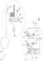
- FIG. 1 illustrates a hazard response network generally referred to as 10 disposed in a building 20 according to a disclosed embodiment.
- the building 20 may have a plurality of partitioned areas generally referred to as 30.
- the partitioned areas 30 may have characteristics distinct from other areas, such as physical location.
- Various ones of the areas 30 may have a respective plurality of hazard response stations therein generally referred to as 40.
- the portioned areas 30 may include a respective plurality of devices generally referred to as 50.
- the plurality of devices 50 may include a respective plurality of hazard detectors generally referred to as 60.
- the plurality of devices 50 may also include a respective plurality of extinguishers generally referred to as 70 including a first extinguisher 72 and a second extinguisher 74, and a respective plurality of station panels generally referred to as 80.
- the extinguishers 70 and the station panels 80 may be disposed in the hazard response stations 40.
- the station panels 80 may be used for providing visual and/or audible alerts or messages as indicated below.
- the plurality of devices 50 may further include a system panel 90, disposed in one of the partitioned areas 30, for monitoring activities around the network 10.
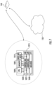
- the network 10 in the building 20 may be one of a plurality of discrete hazard response networks distributed among different floors and/or portions of same floor in the building 20. Each discrete network may be considered a hazard response neighborhood, also generally referenced as 95. Devices 50 registered to a neighborhood 10 may alternatively be referred to as neighborhood devices 50.
- the extinguishers 70 may comprise a respective plurality of cylinders generally referred to as 100, with suppressant 110 therein.
- the extinguishers 70 may include a respective plurality of pressure sensors generally referred to as 120 and a respective plurality of positional sensors generally referred to as 130.
- the plurality of devices 50 may include a respective plurality of controllers generally referred to as 140 that provide for communicating over a telecommunications network 150 and performing algorithms or calculations as described below with respect to FIGS. 2-7 .
- various ones of the devices 50 may be capable of performing one or more processes generally including: S10 of issuing self-identifying broadcasts; S20 of monitoring neighborhood communications to detect other self-identifying broadcasts and thereby track an inventory of neighborhood devices 50; S30 of monitoring neighborhood communication to detect when a neighborhood device 50 is being utilized to address an alert condition; S40 of issuing a maintenance request; and S50 of monitoring neighborhood communications to identify a maintenance request from another neighborhood device 50.
- S10 of issuing self-identifying broadcasts S20 of monitoring neighborhood communications to detect other self-identifying broadcasts and thereby track an inventory of neighborhood devices 50
- S30 of monitoring neighborhood communication to detect when a neighborhood device 50 is being utilized to address an alert condition
- S40 of issuing a maintenance request S50 of monitoring neighborhood communications to identify a maintenance request from another neighborhood device 50.
- the extinguishers 70 may each be configured to perform processes S10-S50.
- the detectors 60 may be each configured to perform processes S10-S30 and S50.
- the station panels 80 may each be configured to perform processes S10, S20 and S50, as well visually displaying and/or audibly sounding alerts.
- the station panels 80 may also be configured to function as routers and/or repeaters for retransmitting information by and between the plurality of neighborhood devices 50 and the system panel 90.
- the system panel 90 may be configured to perform processes S20, S30 and S50, and instruct station panels 80 on processing alerts by displaying and/or announcing relevant information.
- FIG. 3A the figure illustrates steps performed by a neighborhood device 50 such as the first extinguisher 72 executes the process S10 of issuing self-identifying broadcasts.
- broadcasts may include a unique ID (identifier) and a device type.
- the device type may be, for example, extinguisher, detector, station panel and other inputs and output modules that are typically used in fire panel installations.
- Such broadcasts may be issued every second.
- FIG. 3B the figure illustrates steps performed by a neighborhood device 50 such as the first extinguisher 72 executing process S20 of monitoring neighborhood communications to detect the addition of another devices 50 such as the second extinguisher 74 to the neighborhood 10. From such monitoring, the system panel 90 and neighborhood devices 50 may track an inventory of all neighborhood devices 50. For example at step S320 the first extinguisher 72 may receive the periodic self-identifying broadcast from the second extinguisher 74. At step S330 the first extinguisher 72 may perform the step of analyzing the signal strength of the self-identifying broadcast from the second extinguisher 74.
- the first extinguisher 72 at step S340 may then perform the step of determining whether the second extinguisher 74 is currently registered as a neighborhood device 50. For example, the first extinguisher 72 may send an inquiry to the system panel 90 and/or may review a list of neighborhood devices stored within memory of the first extinguisher 72. If the second extinguisher 74 is not currently registered as a neighborhood device 50, step S20 may include step S350 of the first extinguisher 72 rebroadcasting the self-identifying broadcast from the second extinguisher 74. In this instance the first extinguisher 72 effectively acts as a broadcast repeater as the broadcast is being transmitted toward the system panel 90.
- the first extinguisher 72 when executing process S20, may perform step S360 receiving the self-identifying broadcast that was transmitted pursuant to step S350 from another neighborhood device 50. The first extinguisher may then execute step S370 of forwarding the broadcast so that it may reach the system panel 90. In this instance the first extinguisher 72 effectively acts as a broadcast repeater and/or router as the broadcast is being transmitted toward the system panel 90.
- station panels 80 also perform steps illustrated under FIG. 3A-3C . Relevant actions of the system panel 90 are indicated below.
- FIG. 4A the figure illustrates steps performed when a neighborhood device 50 such as the first extinguisher 72 executes the process S30 of monitoring communications to determine when another neighborhood device 50 such as the second extinguisher 74 is being utilized to address an alert condition.
- the first extinguisher 72 determines that the self-identifying broadcast from the second extinguisher 74 has not been received for a predetermined period of time. For example, if each neighborhood devices 50 issues a self-identifying broadcast every second, the predetermined period of time may be three seconds. From this the first extinguisher 72 at step S420 may determine the second extinguisher 74 is being utilized to address an alert condition.
- the first extinguisher 72 broadcasts that second extinguisher activities have implicated the existence of an alert condition.
- a decreased signal strength may be relied upon by the first extinguisher 72 to determine that second neighborhood device 50 such as the second extinguisher 74 is being utilized to respond to an alert condition.
- the first extinguisher 72 may perform the step of maintaining a running average of the signal strength from the self-identifying broadcast from the second extinguisher 74.
- the first extinguisher 72 may perform the step of identifying when the signal strength diverges from the running average by more than a threshold. Thereafter the process follows step S420 and S430.
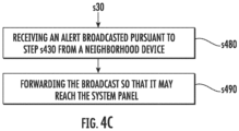
- the first extinguisher 72 may perform step S480 receiving an alert broadcasted pursuant to step S430 from another neighborhood device 50 such as the second extinguisher 72.
- the first extinguisher may then execute step S490 of forwarding the broadcast so that it may reach the system panel 90.
- the first extinguisher 72 again effectively acts as a broadcast repeater and/or router as the broadcast is being transmitted toward the system panel 90.
- station panels 80 also perform steps illustrated under FIGS. 4A-4C . Relevant actions of the system panel 90 are indicated below.
- the figure illustrates steps performed according to a disclosed embodiment wherein a neighborhood device 50 issues a maintenance request as in step s40.
- the first extinguisher 72 may determine that a scheduled maintenance is due (for example suppressant 110 has expired) or that or a triggered maintenance event has occurred (for example pressure within the first extinguisher 72 falls below a set point as sensed from the first sensor 120, or that the extinguisher 72 has fallen over as sensed from the second sensor 130).
- the first extinguisher 72 may perform the step of issuing the maintenance alert to the system panel 90.
- FIG. 5B illustrates when the first extinguisher 72 executes S50 by at step 530 receiving a broadcasted maintenance request from a neighborhood device 50 such as the second extinguisher 74.
- the first extinguisher 72 may then execute step S550 of forwarding the broadcast so that it may reach the system panel 90.
- the first extinguisher 72 effectively acts as a broadcast repeater and/or router as the broadcast is being transmitted toward the system panel 90.
- station panels 80 also perform steps illustrated under FIG. 5B . Relevant actions of the system panel 90 are discussed below.
- FIG. 6A the figure illustrates steps performed according to a disclosed embodiment wherein a system panel 90 identifies new devices in a network under S30. Based on steps illustrated in FIGS. 3A-3C above the system panel 90 may perform step S610 of directly detecting the presence of a newly added neighborhood device 50 or receiving a forwarded broadcast that identifies the newly added neighborhood device. From this the system panel 90 may perform step s615 of determining that the second extinguisher has joined the neighborhood 10.
- the system panel 90 may perform step S620 of recording the existence of the second extinguisher 74. Then the system panel 90 performs step S630 of broadcasting instruction to the system devices 50 to update respective lists to account for all neighborhood devices 50. Upon receiving the broadcast under S630, network devices 50 will update their lists and retransmit the broadcast so that all devices in the neighborhood are assured to receive the broadcast.
- FIG. 6B the figure illustrates steps performed according to a disclosed embodiment wherein a system panel 90 identifies that actions of a device 50, such as the second extinguisher 74, implicate the existence of an alert condition.
- the system panel 90 may perform step S640 of directly detecting the action of a neighborhood device implicates the existence of an alert condition or receiving a forwarded broadcast that identifies an alert condition.
- the system panel 90 may then perform the step S645 of determining that an alert condition exists.
- system panel 90 determines that an alert condition exists after directly detecting within a predetermined period of time the action of at least two neighborhood devices that implicates the existence of an alert condition. Alternatively the system panel 90 determines that an alert condition exists after receiving forwarded broadcast within a predetermined period of time that implicate an alert condition exists based on the actions of at least two neighborhood devices 50.
- the system panel 90 may perform step S650 of broadcasting instruction to the station panels 80 to visually and/or audibly indicate that an alert condition exists.
- the system panel 90 may broadcast instructions to the station panels 80 having available extinguishers (for example excluding the panel 80 in the same station 40 assigned to the second extinguisher 74) to indicate the availability of the respective fire extinguishers 70.
- FIG. 6C the figure illustrates steps performed according to a disclosed embodiment wherein a system panel 90 identifies a maintenance issue exists with a neighborhood device 50.
- the system panel 90 may perform step S670 of directly receiving broadcasts that identify a need for maintenance from a neighborhood device 50 or receiving a forwarded broadcast that identifies the need for maintenance from a neighborhood device 50. From this the neighborhood panel 90 may perform the step S675 of determining that a neighborhood device needs maintenance.
- the system panel 90 Upon determining that a neighborhood device 50 needs maintenance, the system panel 90 performs step S680 of broadcasting instructions directed to the station panel 80 associated with the device 50 that needs maintenance. Such station panel 80 would be in the same station 40 as the device needing maintenance. The instructions may be for the station panel 80 to visually and/or audibly advertise that the device 80 needs maintenance and the type of maintenance needed.
- the various neighborhood devices 50 may serve as broadcast repeaters and/or routers to assure that the targeted station panel 80 receives the broadcasted instructions and can act upon the same.
- the above disclosure may provide use of wireless methods to integrate portable fire extinguisher cylinders ("cylinders") with a fire panel (the system panel).
- the disclosed embodiments may provide for (i) monitoring a readiness of a cylinder, (ii) alerting of low pressure conditions in the cylinders, and maintenance needs and service reminders for the cylinders, (iii) alerting (visually/acoustically) of non-availability of the cylinders such as cylinders falling and/or missing from installed locations and/or imminent expiration of cylinder contents, and (iv) alerting a surrounding area of the presence of the cylinder during a fire condition.
- the fire panel may be configured according to its topological configuration that includes connected devices, their identification, types of detectors, device specific parameters, and corresponding input and output correlations.
- fire detectors and extinguishers may be assigned different categories along with their unique ID.
- the various devices and the system panel in a predetermined proximity may learn about each other and store relevant information i.e. device ID, device type, signal strength, etc.
- Normal operational steps may include each device receiving data from other devices in proximity and monitoring carrier signal strength for such data. Additional steps may include each device continuously averaging carrier signal strength for data transfers and applying filters to eliminate noise from the carrier signals.
- a device may determine that the extinguisher is being moved. The device may send an alert condition to the fire panel for the particular extinguisher. If one or more devices are reporting alert conditions of a fire extinguisher within predetermined period of time, the fire panel may then activate the station panels, which may be LED (light emitting diode) sign boards among the plurality of fire extinguishers and provide audible and visible alerts.
- the station panels may be LED (light emitting diode) sign boards among the plurality of fire extinguishers and provide audible and visible alerts.
- Benefits of the above disclosed embodiments may include (i) a preparedness for a fire emergency due to notice of low pressure in a cylinder, (ii) a local notice during a fire from integrated fire panels, which may include flashings that direct local occupants to an extinguisher, (iii) a notice on local panels of abnormalities and service reminders, (iv) a relatively easy integration with legacy bases, (v) providing notice for any attention that may be needed of a change of location or unavailability at a location of an extinguisher (vi) providing a notice of a rapid a change or fall of an extinguisher from mounting location.
- controllers 140 may communicate over the network 150.
- the controllers may have substantially the same technology features.
- the controllers 140 may be a computing device that includes processing circuitry that may further include an application specific integrated circuit (ASIC), an electronic circuit with one or more elemental circuit components such as resistors, an electronic processor (shared, dedicated, or group) 1004 and memory 1005 that executes one or more software algorithms or firmware algorithms and programs, contains relevant data which may be dynamically collected or disposed in one or more look-up tables, a combinational logic circuit that contains one or more operational amplifiers, and/or other suitable interfaces and components that provide the described functionality.
- the processor 1004 processes data stored in the memory 1005 and employs the data in various control algorithms, diagnostics and the like including those illustrated in FIGS. 2-6C .
- the controller 140 may further include, in addition to a processor 1004 and memory 1005, one or more input and/or output (I/O) device interface(s) 1010 that are communicatively coupled via an onboard (local) interface to communicate among the plurality of controllers.
- the onboard interface may include, for example but not limited to, an onboard system bus 1015, including a control bus 140 (for inter-device communications), an address bus 1025 (for physical addressing) and a data bus 1040 (for transferring data). That is, the system bus 1015 enables the electronic communications between the processor 1004, memory 1005 and I/O connections 1100.
- the I/O connections 1010 may also include wired connections and/or wireless connections.
- the onboard interface may have additional elements, which are omitted for simplicity, such as controllers, buffers (caches), drivers, repeaters, and receivers to enable electronic communications.
- the processor 1004 onboard the controller 20 may be configured to execute software algorithms stored within the memory 1005, including those illustrated in FIGS. 2-6C , to communicate data to and from the memory 1005, and to generally control computing operations pursuant to the software algorithms.
- the algorithms in the memory 1005, in whole or in part, may be read by the processor 1004, perhaps buffered within the processor 1004, and then executed.
- the processor 1004 may include hardware devices for executing the algorithms, particularly algorithms stored in memory 1005.
- the processor 1004 may be a custom made or a commercially available processor 1004, a central processing units (CPU), an auxiliary processor among several processors associated with computing devices, semiconductor based microprocessors (in the form of microchips or chip sets), or generally any such devices for executing software algorithms.
- the memory 1005 onboard the controller 140 may include any one or combination of volatile memory elements (e.g., random access memory (RAM, such as DRAM, SRAM, SDRAM, VRAM, etc.)) and/or nonvolatile memory elements (e.g., ROM, hard drive, tape, CD-ROM, etc.). Moreover, the memory 1005 may incorporate electronic, magnetic, optical, and/or other types of storage media. The memory 1005 may also have a distributed architecture, where various components are situated remotely from one another, but may be accessed by the processor 1004.
- the software algorithms in the memory 1005 onboard the controller 20 may include one or more separate programs, each of which includes an ordered listing of executable instructions for implementing logical functions.
- a system component embodied as software algorithms may be construed as a source program, executable program (object code), script, or any other entity comprising a set of instructions to be performed.
- the software algorithms When constructed as a source program, the software algorithms may be translated via a compiler, assembler, interpreter, or the like, which may or may not be included within the memory.
- Software algorithms may be capable of handling various protocols for transmissions selectable as needed for an application interface.
- I/O input/output
- controller 20 uses the system I/O Interface(s) 1010, the wired interfaces and/or the wireless interfaces to now be identified but the illustration of which shall be omitted for brevity.
- I/O devices include, but are not limited to (i) input devices such as a keyboard, mouse, scanner, microphone, camera, proximity device, etc., (ii) output devices such as a printer, display, etc., and (iii) devices that communicate both as inputs and outputs, such as a modulator/demodulator (modem; for accessing another device, system, or network), a radio frequency (RF) or other transceiver, a telephonic interface, a bridge, a router and other modes of wired and wireless communications, etc.
- modem modulator/demodulator
- RF radio frequency
- the controller 20 may communicate over the network 150 by applying electronic short range communication (SRC) protocols.
- SRC electronic short range communication
- Such protocols may include local area network (LAN) protocols and/or a private area network (PAN) protocols.
- LAN protocols include Wi-Fi technology, which is a technology based on the Section 802.10 standards from the Institute of Electrical and Electronics Engineers, or IEEE.
- PAN protocols include, for example, Bluetooth Low Energy (BTLE), which is a wireless technology standard designed and marketed by the Bluetooth Special Interest Group (SIG) for exchanging data over short distances using short-wavelength radio waves.
- BTLE Bluetooth Low Energy
- SIG Bluetooth Special Interest Group
- PAN protocols also include ultra-wideband (UWB), Zigbee, a technology based on Section 802.15.4 protocols from the Institute of Electrical and Electronics Engineers (IEEE).
- Zigbee represents a suite of high-level communication protocols used to create personal area networks with small, low-power digital radios for low-power low-bandwidth needs, and is best suited for small scale projects using wireless connections.
- wireless connection may include Radio-frequency identification (RFID) technology, which is another SRC technology used for communicating with an integrated chip (IC) on an RFID smartcard.
- RFID Radio-frequency identification
- controller 140 may be implemented using software algorithms.
- software algorithms such functionality may be represented as a module, segment, or portion of code, which comprises one or more executable instructions for implementing the specified logical function(s). It should also be noted that such modules may not necessarily be executed in any particular order and/or executed at all.
- controller 140 can be embodied in any non-transitory computer-readable medium for use by or in connection with an instruction execution system, apparatus, or device, such as a computer-based system, processor-containing system, or other system that can fetch the instructions from the instruction execution system, apparatus, or device and execute the instructions.
- a "computer-readable medium” contains, stores, communicates, propagates and/or transports the program for use by or in connection with the instruction execution system, apparatus, or device.
- the computer readable medium in the controller 140 may include various forms of computer readable memory 1005.
- the computer readable memory 1005 may be integral to an apparatus or device, which may include one or more semiconductors, and in which the communication and/or storage technology may be one or more of electronic, magnetic, optical, electromagnetic or infrared.
- a computer-readable medium the illustration of which being omitted for brevity
- a portable computer diskette magnetic
- RAM random access memory
- ROM read-only memory
- EPROM or Flash memory erasable programmable read-only memory
- CDROM compact disc read-only memory
- each of the controllers on the same side of the network may be the same device such that no network there between is required.
- a single on-site controller is provided instead of the distributed system of controllers.
- the controllers on the same side of the network are controlled by servers located over the World Wide Web, using a cloud computing configuration.
- the distributed controller network is hard-wired for all telecommunication services so that no wireless network is necessary.
- redundant wireless and wired networks are utilized which automatically switch between such services to minimize network congestion and eliminate single points of failure.
Landscapes
- Business, Economics & Management (AREA)
- Emergency Management (AREA)
- Engineering & Computer Science (AREA)
- Computer Networks & Wireless Communication (AREA)
- Signal Processing (AREA)
- Physics & Mathematics (AREA)
- General Physics & Mathematics (AREA)
- Health & Medical Sciences (AREA)
- Public Health (AREA)
- Environmental & Geological Engineering (AREA)
- Alarm Systems (AREA)
Claims (15)
- System, umfassend:
eine erste Vorrichtung (72) aus einer Vielzahl von Vorrichtungen (50), die über ein Netzwerk (10) wirkverbunden ist, wobei die erste Vorrichtung (72) für folgende Aufgaben konfiguriert ist:Überwachen des Netzwerks (10) auf sich selbst identifizierende Sendungen, die eine eindeutige Kennung und einen Vorrichtungstyp aus der Vielzahl von Vorrichtungen (50) enthalten,Empfangen über das Netzwerk (10) selbstidentifizierender Sendungen von einer zweiten Vorrichtung (74), wobei die erste Vorrichtung (72) ein Gefahrenlöscher, ein Gefahrendetektor oder ein Panel zur selektiven visuellen und/oder akustischen Weiterleitung einer Formation ist, und die zweite Vorrichtung (74) ein Gefahrenlöscher ist,Bestimmen, dass die zweite Vorrichtung (74) neu im Netzwerk (10) ist, wenn die zweite Vorrichtung (74) derzeit nicht als im Netzwerk (10) registriert ist und die Signalstärke der sich selbst identifizierenden Sendungen für die zweite Vorrichtung (74) oberhalb einer ersten Signalstärke-Schwelle liegt, wobei die erste Vorrichtung (72) konfiguriert ist, um zu bestimmen, dass die zweite Vorrichtung (74) derzeit nicht als im Netzwerk (10) registriert ist, durch Überprüfen einer Liste von Vorrichtungen, die im Speicher der ersten Vorrichtung (72) gespeichert sind,Erneutes Senden der selbstidentifizierenden Sendung von der zweiten Vorrichtung (74), um ein Systempanel (90) zu erreichen, das konfiguriert ist, um Aktivitäten um das Netzwerk (10) zu überwachen und das Vorhandensein einer neu hinzugefügten Vorrichtung aufzuzeichnen, undAktualisieren der Vorrichtungsliste, um die zweite Vorrichtung (74) zu berücksichtigen, wenn Sendungsanweisungen von der Systemsteuerung (90) empfangen werden. - System nach Anspruch 1, wobei die erste Vorrichtung (72) konfiguriert ist, um zu bestimmen, dass die zweite Vorrichtung (74) aktuell als im Netzwerk (10) registriert ist und dass eine Signalstärke der sich selbst identifizierenden Sendungen für die zweite Vorrichtung (74) oberhalb der ersten Signalstärke-Schwelle liegt.
- System nach Anspruch 1, wobei die erste Vorrichtung (72) für folgende Aufgaben konfiguriert ist:Überwachen des Netzwerks (10) auf Alarmzustände basierend auf Aktivitäten der zweiten Vorrichtung (74), undSenden einer Warnmeldung in das Netzwerk, wenn die erste Vorrichtung (72) erkennt, dass eine Warnbedingung vorliegt.
- System nach Anspruch 3, wobei die erste Vorrichtung (72) konfiguriert ist, um eine Warnbedingung zu identifizieren, wenn es nicht gelingt, periodische selbstidentifizierende Sendungen von der zweiten Vorrichtung (74) für eine Zeitspanne zu empfangen, die größer als ein erster Zeitschwellenwert ist.
- System nach Anspruch 3, wobei die erste Vorrichtung (72) konfiguriert ist, um eine Warnbedingung zu identifizieren, wenn periodische selbstidentifizierende Sendungen von der zweiten Vorrichtung (74) für eine Zeitspanne, die größer als eine zweite Zeitschwelle ist, unter eine zweite Signalstärkeschwelle fallen.
- System nach Anspruch 5, wobei die erste Vorrichtung (72) dazu konfiguriert ist, das Netzwerk auf eine Wartungsanforderung von der zweiten Vorrichtung (74) zu überwachen, und, wenn die erste Vorrichtung (72) die Wartungsanforderung von der zweiten Vorrichtung (74) empfängt, die Wartungsanforderung erneut in das Netzwerk zu übertragen.
- System nach Anspruch 5, wobei die erste Vorrichtung (72) konfiguriert ist, um von einer anderen Vorrichtung im Netzwerk (10) eine Übertragung zu empfangen, die anzeigt, dass eine oder mehrere von (i) der zweiten Vorrichtung (74) neu im Netzwerk (10) ist, (ii) eine Alarmbedingung im Netzwerk (10) vorliegt, (iii) die zweite Vorrichtung (74) wartungsbedürftig ist, und die erste Vorrichtung (72) die Übertragung erneut an das Netzwerk (10) sendet.
- System nach Anspruch 7, umfassend das Systempanel (90), wobei das Systempanel (90) direkt oder über wiederübertragene Sendungen konfiguriert ist, um zu:(i) Bestimmen, dass die zweite Vorrichtung (74) dem Netzwerk (10) hinzugefügt wird, und Senden von Anweisungen an Netzwerkgeräte, um die zweite Vorrichtung (74) als Teil des Netzwerks (10) zu erkennen;(ii) Bestimmen, dass eine Alarmbedingung vorliegt, und um Anweisungen an Stationspanels (80) zu senden, um visuell und/oder akustisch anzuzeigen, dass eine Alarmbedingung vorliegt; und(iii) Bestimmen, dass die zweite Vorrichtung (74) Wartungs- und Sendungsanweisungen benötigt, die an eines von mehreren Stationspanels (80) im Netzwerk gerichtet sind, um (10) visuell und/oder akustisch anzuzeigen, dass die zweite Vorrichtung (74) eine Wartung benötigt.
- ein Verfahren zum Überwachen eines Systems durch eine erste Vorrichtung (72) einer Mehrzahl von Vorrichtungen (50), die über ein Netzwerk (10) in Wirkverbindung stehen,
Verfahren mit der ersten Vorrichtung (72):Überwachen des Netzwerks auf sich selbst identifizierende Sendungen, die eine eindeutige Kennung und einen Vorrichtungstyp aus der Vielzahl von Vorrichtungen (50) enthalten, undEmpfangen über das Netzwerk selbstidentifizierender Sendungen von einer zweiten Vorrichtung (74), wobei die erste Vorrichtung (72) ein Gefahrenlöscher, ein Gefahrendetektor oder ein Panel zur selektiven visuellen und/oder akustischen Weiterleitung einer Formation ist, und die zweite Vorrichtung (74) ein Gefahrenlöscher ist,Bestimmen, dass die zweite Vorrichtung (74) neu im Netzwerk (10) ist, wenn die zweite Vorrichtung (74) derzeit nicht als im Netzwerk (10) registriert ist und die Signalstärke der sich selbst identifizierenden Sendungen für die zweite Vorrichtung (74) oberhalb eines ersten Signalstärkeschwellwerts liegt, und Bestimmen, dass die zweite Vorrichtung (74) derzeit nicht als im Netzwerk (10) registriert ist, durch Überprüfen einer Liste von Vorrichtungen, die im Speicher der ersten Vorrichtung (72) gespeichert sind, erneutes Senden der sich selbst identifizierenden Sendung von der zweiten Vorrichtung (74), um ein Systempanel (90) zu erreichen, das konfiguriert ist, um Aktivitäten rund um das Netzwerk (10) zu überwachen und zur Aufzeichnung des Vorliegens einer neu hinzugefügten Vorrichtung, undAktualisieren der zu Vorrichtungsliste, um die zweite Vorrichtung (74) zu berücksichtigen, wenn Sendungsanweisungen von der Systemsteuerung (90) empfangen werden. - Verfahren nach Anspruch 9, wobei die erste Vorrichtung (72) bestimmt, dass die zweite Vorrichtung (74) aktuell als im Netzwerk (10) registriert ist und dass eine Signalstärke der sich selbst identifizierenden Sendungen für die zweite Vorrichtung (74) oberhalb der ersten Signalstärke-Schwelle liegt.
- Verfahren nach Anspruch 9, wobei die erste Vorrichtung (72):Überwachen des Netzwerks (10) auf Alarmzustände basierend auf Aktivitäten der zweiten Vorrichtung (74), undSenden einer Warnmeldung in das Netzwerk (10) durch die erste Vorrichtung (72), wenn die erste Vorrichtung (72) eine Warnbedingung feststellt.
- Verfahren nach Anspruch 11, wobei die erste Vorrichtung (72) eine Warnbedingung identifiziert, wenn es nicht gelingt, periodische selbstidentifizierende Sendungen von der zweiten Vorrichtung (74) für eine Zeitspanne zu empfangen, die größer als ein erster Zeitschwellenwert ist.
- Verfahren nach Anspruch 11, wobei die erste Vorrichtung (72) eine Warnbedingung identifiziert, wenn periodische selbstidentifizierende Sendungen von der zweiten Vorrichtung (74) für eine Zeitspanne, die größer als eine zweite Zeitschwelle ist, unter eine zweite Signalstärkeschwelle fallen.
- Verfahren nach Anspruch 13, wobei die erste Vorrichtung (72) das Netzwerk (10) auf eine Wartungsanforderung von der zweiten Vorrichtung (74) überwacht, und wenn die erste Vorrichtung (72) die Wartungsanforderung von der zweiten Vorrichtung (74) empfängt, die erste Vorrichtung (72) die Wartungsanforderung erneut in das Netzwerk (10) sendet.
- Verfahren nach Anspruch 13, wobei die erste Vorrichtung (72) eine Übertragung von einer anderen Vorrichtung im Netzwerk empfängt, die anzeigt, dass eine oder mehrere von (i) der zweiten Vorrichtung (74) neu im Netzwerk (10) ist, (ii) eine Alarmbedingung im Netzwerk (10) vorliegt, (iii) die zweite Vorrichtung (74) wartungsbedürftig ist, und die erste Vorrichtung (72) die Übertragung erneut an das Netzwerk (10) sendet;
vorzugsweise umfassend das Systempanel (90) direkt oder über weiterübertragene Sendungen:(i) Bestimmen, dass die zweite Vorrichtung (74) dem Netzwerk (10) hinzugefügt wird, und Senden von Anweisungen an Netzwerkgeräte, um die zweite Vorrichtung (74) als Teil des Netzwerks (10) zu erkennen;(ii) Bestimmen, dass eine Alarmbedingung vorliegt, und um Anweisungen an Stationspanels (80) zu senden, um visuell und/oder akustisch anzuzeigen, dass eine Alarmbedingung vorliegt; und(iii) Bestimmen, dass die zweite Vorrichtung (74) Wartungs- und Sendungsanweisungen benötigt, die an eines von mehreren Stationspanels (80) im Netzwerk (10) gerichtet sind, um visuell und/oder akustisch anzuzeigen, dass die zweite Vorrichtung (74) eine Wartung benötigt.
Applications Claiming Priority (2)
| Application Number | Priority Date | Filing Date | Title |
|---|---|---|---|
| IN201811046107 | 2018-12-06 | ||
| PCT/US2019/064405 WO2020117904A1 (en) | 2018-12-06 | 2019-12-04 | Networked hazard detectors which monitor for readiness and availability |
Publications (2)
| Publication Number | Publication Date |
|---|---|
| EP3892018A1 EP3892018A1 (de) | 2021-10-13 |
| EP3892018B1 true EP3892018B1 (de) | 2024-11-20 |
Family
ID=69006010
Family Applications (1)
| Application Number | Title | Priority Date | Filing Date |
|---|---|---|---|
| EP19828077.8A Active EP3892018B1 (de) | 2018-12-06 | 2019-12-04 | Vernetzte gefahrenmelder mit überwachung der bereitschaft und verfügbarkeit |
Country Status (4)
| Country | Link |
|---|---|
| US (1) | US11602655B2 (de) |
| EP (1) | EP3892018B1 (de) |
| ES (1) | ES2994471T3 (de) |
| WO (1) | WO2020117904A1 (de) |
Families Citing this family (1)
| Publication number | Priority date | Publication date | Assignee | Title |
|---|---|---|---|---|
| CN116022624A (zh) | 2021-10-25 | 2023-04-28 | 奥的斯电梯公司 | 电梯绳索伸长检测装置和检测方法以及电梯 |
Family Cites Families (52)
| Publication number | Priority date | Publication date | Assignee | Title |
|---|---|---|---|---|
| US4363031A (en) * | 1980-07-07 | 1982-12-07 | Jack Reinowitz | Wireless alarm system |
| US5898369A (en) * | 1996-01-18 | 1999-04-27 | Godwin; Paul K. | Communicating hazardous condition detector |
| US7728715B2 (en) * | 1996-01-23 | 2010-06-01 | En-Gauge, Inc. | Remote monitoring |
| US7174783B2 (en) * | 1996-01-23 | 2007-02-13 | Mija Industries, Inc. | Remote monitoring of fluid containers |
| US7188679B2 (en) | 1996-01-23 | 2007-03-13 | Mija Industries, Inc. | Remote fire extinguisher station inspection |
| US6078269A (en) * | 1997-11-10 | 2000-06-20 | Safenight Technology Inc. | Battery-powered, RF-interconnected detector sensor system |
| US6759956B2 (en) * | 1998-10-23 | 2004-07-06 | Royal Thoughts, L.L.C. | Bi-directional wireless detection system |
| US6768424B1 (en) * | 1999-01-21 | 2004-07-27 | Gary J. Morris | Environmental condition detector with remote fire extinguisher locator system |
| US6598454B2 (en) | 2001-07-30 | 2003-07-29 | Bs&B Safety Systems, Inc. | System and method for monitoring a pressurized system |
| US7081815B2 (en) * | 2001-08-23 | 2006-07-25 | Battelle Memorial Institute | Radio frequency security system, method for a building facility or the like, and apparatus and methods for remotely monitoring the status of fire extinguishers |
| GB0211644D0 (en) | 2002-05-21 | 2002-07-03 | Wesby Philip B | System and method for remote asset management |
| US7495544B2 (en) * | 2003-02-03 | 2009-02-24 | Ingrid, Inc. | Component diversity in a RFID security network |
| US8069470B1 (en) * | 2005-04-13 | 2011-11-29 | Oracle America, Inc. | Identity and authentication in a wireless network |
| FR2893743B1 (fr) * | 2005-11-10 | 2010-10-29 | Smart Packaging Solutions Sps | Procede et dispositif de detection d'incendie en foret |
| KR100794782B1 (ko) | 2006-12-29 | 2008-01-15 | 한국남동발전 주식회사 | 소화기 충전압력 자동경보 장치 |
| US8253574B2 (en) * | 2006-12-29 | 2012-08-28 | Honeywell International Inc. | Systems and methods to predict fire and smoke propagation |
| DE602008003542D1 (de) * | 2007-01-17 | 2010-12-30 | Panasonic Elec Works Co Ltd | Funkkommunikationssystem |
| US8378808B1 (en) * | 2007-04-06 | 2013-02-19 | Torrain Gwaltney | Dual intercom-interfaced smoke/fire detection system and associated method |
| US8385322B2 (en) * | 2007-07-30 | 2013-02-26 | Innovative Wireless Technologies, Inc. | Distributed ad hoc network protocol using synchronous shared beacon signaling |
| US7733235B2 (en) * | 2007-10-30 | 2010-06-08 | Herbert Baker | Wireless smoke and fire detection system and method |
| US8981927B2 (en) | 2008-02-13 | 2015-03-17 | En-Gauge, Inc. | Object Tracking with emergency equipment |
| US8749373B2 (en) * | 2008-02-13 | 2014-06-10 | En-Gauge, Inc. | Emergency equipment power sources |
| TWI384855B (zh) * | 2008-04-02 | 2013-02-01 | Inventec Appliances Corp | 行動裝置之防盜系統 |
| FR2931364A1 (fr) | 2008-05-20 | 2009-11-27 | Gall Paul Le | Dispositif extincteur, systeme de surveillance de l'etat de charge de tels extincteurs et procede pour le montage de tels dispositifs extincteurs |
| US20090301739A1 (en) * | 2008-06-04 | 2009-12-10 | Infineon Technologies Ag | Pressure sensing apparatuses, systems and methods |
| ITTO20080643A1 (it) | 2008-08-25 | 2010-02-26 | Sabatino Pompa | Apparato di segnalazione di posizione di estintori |
| KR101029554B1 (ko) | 2009-07-02 | 2011-04-18 | 강윤범 | 다기능 휴대용 소화기 시스템 |
| US9041534B2 (en) | 2011-01-26 | 2015-05-26 | En-Gauge, Inc. | Fluid container resource management |
| US9253635B2 (en) * | 2011-02-09 | 2016-02-02 | Cubic Corporation | Low power wireless network for transportation and logistics |
| FR2977966B1 (fr) | 2011-07-12 | 2014-06-13 | Finsecur | Procede d'identification d'extincteur et dispositif d'identification d'extincteur |
| FR2977965B1 (fr) * | 2011-07-12 | 2014-06-06 | Finsecur | Procede d'identification d'extincteur et dispositif d'identification d'extincteur |
| US9541625B2 (en) | 2011-08-25 | 2017-01-10 | En-Gauge, Inc. | Emergency resource location and status |
| US8842016B1 (en) * | 2011-09-06 | 2014-09-23 | Cellco Partnership | Fire extinguisher notification system and method of use |
| US8937879B2 (en) * | 2012-03-30 | 2015-01-20 | General Electric Company | System and method for changing network topology based on energy consumption |
| US9480014B2 (en) * | 2012-06-01 | 2016-10-25 | Qualcomm Incorporated | Device configuration in a hybrid communication network |
| US9155928B2 (en) | 2012-07-19 | 2015-10-13 | Carolina VILAS BLANCO | Control system for fire prevention facilities |
| US8792645B2 (en) * | 2012-12-18 | 2014-07-29 | Honeywell International Inc. | Authentication and data security for wireless networks |
| HUE034400T2 (en) | 2012-12-28 | 2018-02-28 | Bp S R L S | Equipment for remote control of fire extinguishers and / or fire hydrants |
| WO2015054225A1 (en) * | 2013-10-07 | 2015-04-16 | Google Inc. | Smart-home hazard detector providing non-alarm status signals at opportune moments |
| EP3084736B1 (de) * | 2013-12-17 | 2019-05-01 | Tyco Fire Products LP | System und verfahren zur erkennung und unterdrückung von bränden mittels windinformationen |
| PL2896432T3 (pl) * | 2014-01-17 | 2016-11-30 | Sposób i instalacja do gaszenia z ciekłym syntetycznym środkiem gaśniczym | |
| US9827456B2 (en) | 2014-05-21 | 2017-11-28 | James Aaron McManama | Firefighting equipment inspection notification device |
| US9860716B2 (en) | 2015-03-31 | 2018-01-02 | Young W. Lee | Fire extinguisher tracking and navigation system |
| US10021529B2 (en) * | 2015-04-21 | 2018-07-10 | Hewlett Packard Enterprise Development Lp | Calibration of wireless network's signal strength map database for indoor locating techniques |
| US9685061B2 (en) * | 2015-05-20 | 2017-06-20 | Google Inc. | Event prioritization and user interfacing for hazard detection in multi-room smart-home environment |
| CN107852661B (zh) * | 2015-05-22 | 2021-09-07 | 亚德诺半导体国际无限责任公司 | 网络管理器和网状网络系统 |
| CN105344053A (zh) | 2015-10-26 | 2016-02-24 | 黄汝逸 | 一种灭火器年检告警器、灭火装置和灭火器年检管理系统 |
| US10010732B2 (en) | 2016-01-22 | 2018-07-03 | Nec Corporation | Apparatus, methods, and systems for monitoring fire extinguisher operational readiness |
| NO341764B1 (en) * | 2016-04-12 | 2018-01-15 | Shoplabs As | Pulse rate |
| US10506688B2 (en) * | 2016-08-24 | 2019-12-10 | Lutron Technology Company Llc | Method of identifying a lighting fixture |
| CN108353348B (zh) * | 2016-09-27 | 2020-03-10 | 华为技术有限公司 | 一种数据连接建立方法及终端设备 |
| CN115735414A (zh) * | 2020-05-01 | 2023-03-03 | 路创技术有限责任公司 | 自动调整用于发现无线控制装置的发现范围 |
-
2019
- 2019-12-04 EP EP19828077.8A patent/EP3892018B1/de active Active
- 2019-12-04 WO PCT/US2019/064405 patent/WO2020117904A1/en not_active Ceased
- 2019-12-04 ES ES19828077T patent/ES2994471T3/es active Active
- 2019-12-04 US US16/973,346 patent/US11602655B2/en active Active
Also Published As
| Publication number | Publication date |
|---|---|
| EP3892018A1 (de) | 2021-10-13 |
| ES2994471T3 (en) | 2025-01-24 |
| WO2020117904A1 (en) | 2020-06-11 |
| US11602655B2 (en) | 2023-03-14 |
| US20210283445A1 (en) | 2021-09-16 |
Similar Documents
| Publication | Publication Date | Title |
|---|---|---|
| CN103517388B (zh) | Wi-Fi火灾检测系统中的接入点同步 | |
| US10592306B2 (en) | Method and apparatus for resource balancing in an automation and alarm architecture | |
| US10629045B1 (en) | System and process for distributed network of redundant central stations | |
| EP2648472A1 (de) | Verfahren zur übertragung von alarminformationen, drahtlose sensorknotenvorrichtung und gatewayknotenvorrichtung | |
| CN110267364A (zh) | Wi-Fi网状网火灾探测系统 | |
| CN112530132B (zh) | 一种基于云计算服务的智能消防管控系统 | |
| US20150277407A1 (en) | Location detection of control equipment in a building | |
| JP2013003926A (ja) | 無線通信システム | |
| JP2008015722A (ja) | データ処理システム | |
| EP3892018B1 (de) | Vernetzte gefahrenmelder mit überwachung der bereitschaft und verfügbarkeit | |
| EP2639779A1 (de) | System für ferninstallierte Schalleinhaltungsprüfung | |
| AU2021233790A1 (en) | System and method for notifying detection of vaping, smoking, or potential bullying | |
| JP5783787B2 (ja) | 火災報知設備 | |
| JP6028073B2 (ja) | 火災報知設備 | |
| JP2006099394A (ja) | 火災検知システムおよび火災検知システムの制御方法 | |
| CN110033589A (zh) | 一种针对敬老院老人的室内位置监控及报警系统 | |
| US7397383B2 (en) | Remote monitoring method with event-triggered warning capability | |
| JP2003248888A (ja) | 火災報知システム | |
| JP2011030094A (ja) | 移動体無線通信システム及びその障害処理方法 | |
| JP5825816B2 (ja) | 火災報知設備 | |
| EP4303844A1 (de) | Alarmsystem, steuerungsvorrichtung und detektor | |
| US20250342955A1 (en) | System and method for call light monitoring | |
| CN116088480B (zh) | 一种设备联动控制方法以及设备控制系统 | |
| EP3868080B1 (de) | Bestimmung einer länge einer sitzungszeitbegrenzungsdauer | |
| CN118075238A (zh) | 通讯地址冲突自诊断方法及装置 |
Legal Events
| Date | Code | Title | Description |
|---|---|---|---|
| STAA | Information on the status of an ep patent application or granted ep patent |
Free format text: STATUS: UNKNOWN |
|
| STAA | Information on the status of an ep patent application or granted ep patent |
Free format text: STATUS: THE INTERNATIONAL PUBLICATION HAS BEEN MADE |
|
| PUAI | Public reference made under article 153(3) epc to a published international application that has entered the european phase |
Free format text: ORIGINAL CODE: 0009012 |
|
| STAA | Information on the status of an ep patent application or granted ep patent |
Free format text: STATUS: REQUEST FOR EXAMINATION WAS MADE |
|
| 17P | Request for examination filed |
Effective date: 20210125 |
|
| AK | Designated contracting states |
Kind code of ref document: A1 Designated state(s): AL AT BE BG CH CY CZ DE DK EE ES FI FR GB GR HR HU IE IS IT LI LT LU LV MC MK MT NL NO PL PT RO RS SE SI SK SM TR |
|
| DAV | Request for validation of the european patent (deleted) | ||
| DAX | Request for extension of the european patent (deleted) | ||
| RIC1 | Information provided on ipc code assigned before grant |
Ipc: H04W 60/00 20090101ALN20240408BHEP Ipc: A62C 13/00 20060101ALN20240408BHEP Ipc: A62C 37/50 20060101ALN20240408BHEP Ipc: H04W 4/38 20180101ALI20240408BHEP Ipc: H04W 84/18 20090101ALI20240408BHEP Ipc: H04W 4/70 20180101ALI20240408BHEP Ipc: H04W 88/04 20090101ALI20240408BHEP Ipc: H04W 4/90 20180101AFI20240408BHEP |
|
| GRAP | Despatch of communication of intention to grant a patent |
Free format text: ORIGINAL CODE: EPIDOSNIGR1 |
|
| STAA | Information on the status of an ep patent application or granted ep patent |
Free format text: STATUS: GRANT OF PATENT IS INTENDED |
|
| RIC1 | Information provided on ipc code assigned before grant |
Ipc: H04W 8/00 20090101ALN20240529BHEP Ipc: H04W 60/00 20090101ALN20240529BHEP Ipc: A62C 13/00 20060101ALN20240529BHEP Ipc: A62C 37/50 20060101ALN20240529BHEP Ipc: H04W 4/38 20180101ALI20240529BHEP Ipc: H04W 84/18 20090101ALI20240529BHEP Ipc: H04W 4/70 20180101ALI20240529BHEP Ipc: H04W 88/04 20090101ALI20240529BHEP Ipc: H04W 4/90 20180101AFI20240529BHEP |
|
| INTG | Intention to grant announced |
Effective date: 20240620 |
|
| GRAS | Grant fee paid |
Free format text: ORIGINAL CODE: EPIDOSNIGR3 |
|
| GRAA | (expected) grant |
Free format text: ORIGINAL CODE: 0009210 |
|
| STAA | Information on the status of an ep patent application or granted ep patent |
Free format text: STATUS: THE PATENT HAS BEEN GRANTED |
|
| AK | Designated contracting states |
Kind code of ref document: B1 Designated state(s): AL AT BE BG CH CY CZ DE DK EE ES FI FR GB GR HR HU IE IS IT LI LT LU LV MC MK MT NL NO PL PT RO RS SE SI SK SM TR |
|
| REG | Reference to a national code |
Ref country code: GB Ref legal event code: FG4D |
|
| REG | Reference to a national code |
Ref country code: CH Ref legal event code: EP |
|
| REG | Reference to a national code |
Ref country code: DE Ref legal event code: R096 Ref document number: 602019062326 Country of ref document: DE |
|
| REG | Reference to a national code |
Ref country code: IE Ref legal event code: FG4D |
|
| REG | Reference to a national code |
Ref country code: ES Ref legal event code: FG2A Ref document number: 2994471 Country of ref document: ES Kind code of ref document: T3 Effective date: 20250124 |
|
| REG | Reference to a national code |
Ref country code: LT Ref legal event code: MG9D |
|
| REG | Reference to a national code |
Ref country code: NL Ref legal event code: MP Effective date: 20241120 |
|
| PG25 | Lapsed in a contracting state [announced via postgrant information from national office to epo] |
Ref country code: HR Free format text: LAPSE BECAUSE OF FAILURE TO SUBMIT A TRANSLATION OF THE DESCRIPTION OR TO PAY THE FEE WITHIN THE PRESCRIBED TIME-LIMIT Effective date: 20241120 Ref country code: PT Free format text: LAPSE BECAUSE OF FAILURE TO SUBMIT A TRANSLATION OF THE DESCRIPTION OR TO PAY THE FEE WITHIN THE PRESCRIBED TIME-LIMIT Effective date: 20250320 Ref country code: IS Free format text: LAPSE BECAUSE OF FAILURE TO SUBMIT A TRANSLATION OF THE DESCRIPTION OR TO PAY THE FEE WITHIN THE PRESCRIBED TIME-LIMIT Effective date: 20250320 |
|
| PG25 | Lapsed in a contracting state [announced via postgrant information from national office to epo] |
Ref country code: FI Free format text: LAPSE BECAUSE OF FAILURE TO SUBMIT A TRANSLATION OF THE DESCRIPTION OR TO PAY THE FEE WITHIN THE PRESCRIBED TIME-LIMIT Effective date: 20241120 Ref country code: NL Free format text: LAPSE BECAUSE OF FAILURE TO SUBMIT A TRANSLATION OF THE DESCRIPTION OR TO PAY THE FEE WITHIN THE PRESCRIBED TIME-LIMIT Effective date: 20241120 |
|
| REG | Reference to a national code |
Ref country code: AT Ref legal event code: MK05 Ref document number: 1744658 Country of ref document: AT Kind code of ref document: T Effective date: 20241120 |
|
| PG25 | Lapsed in a contracting state [announced via postgrant information from national office to epo] |
Ref country code: BG Free format text: LAPSE BECAUSE OF FAILURE TO SUBMIT A TRANSLATION OF THE DESCRIPTION OR TO PAY THE FEE WITHIN THE PRESCRIBED TIME-LIMIT Effective date: 20241120 |
|
| PGFP | Annual fee paid to national office [announced via postgrant information from national office to epo] |
Ref country code: ES Payment date: 20250103 Year of fee payment: 6 |
|
| PG25 | Lapsed in a contracting state [announced via postgrant information from national office to epo] |
Ref country code: NO Free format text: LAPSE BECAUSE OF FAILURE TO SUBMIT A TRANSLATION OF THE DESCRIPTION OR TO PAY THE FEE WITHIN THE PRESCRIBED TIME-LIMIT Effective date: 20250220 |
|
| PG25 | Lapsed in a contracting state [announced via postgrant information from national office to epo] |
Ref country code: AT Free format text: LAPSE BECAUSE OF FAILURE TO SUBMIT A TRANSLATION OF THE DESCRIPTION OR TO PAY THE FEE WITHIN THE PRESCRIBED TIME-LIMIT Effective date: 20241120 Ref country code: GR Free format text: LAPSE BECAUSE OF FAILURE TO SUBMIT A TRANSLATION OF THE DESCRIPTION OR TO PAY THE FEE WITHIN THE PRESCRIBED TIME-LIMIT Effective date: 20250221 Ref country code: LV Free format text: LAPSE BECAUSE OF FAILURE TO SUBMIT A TRANSLATION OF THE DESCRIPTION OR TO PAY THE FEE WITHIN THE PRESCRIBED TIME-LIMIT Effective date: 20241120 |
|
| PG25 | Lapsed in a contracting state [announced via postgrant information from national office to epo] |
Ref country code: PL Free format text: LAPSE BECAUSE OF FAILURE TO SUBMIT A TRANSLATION OF THE DESCRIPTION OR TO PAY THE FEE WITHIN THE PRESCRIBED TIME-LIMIT Effective date: 20241120 |
|
| PG25 | Lapsed in a contracting state [announced via postgrant information from national office to epo] |
Ref country code: RS Free format text: LAPSE BECAUSE OF FAILURE TO SUBMIT A TRANSLATION OF THE DESCRIPTION OR TO PAY THE FEE WITHIN THE PRESCRIBED TIME-LIMIT Effective date: 20250220 |
|
| REG | Reference to a national code |
Ref country code: DE Ref legal event code: R119 Ref document number: 602019062326 Country of ref document: DE |
|
| PG25 | Lapsed in a contracting state [announced via postgrant information from national office to epo] |
Ref country code: SM Free format text: LAPSE BECAUSE OF FAILURE TO SUBMIT A TRANSLATION OF THE DESCRIPTION OR TO PAY THE FEE WITHIN THE PRESCRIBED TIME-LIMIT Effective date: 20241120 |
|
| PG25 | Lapsed in a contracting state [announced via postgrant information from national office to epo] |
Ref country code: DK Free format text: LAPSE BECAUSE OF FAILURE TO SUBMIT A TRANSLATION OF THE DESCRIPTION OR TO PAY THE FEE WITHIN THE PRESCRIBED TIME-LIMIT Effective date: 20241120 |
|
| PG25 | Lapsed in a contracting state [announced via postgrant information from national office to epo] |
Ref country code: EE Free format text: LAPSE BECAUSE OF FAILURE TO SUBMIT A TRANSLATION OF THE DESCRIPTION OR TO PAY THE FEE WITHIN THE PRESCRIBED TIME-LIMIT Effective date: 20241120 |
|
| PG25 | Lapsed in a contracting state [announced via postgrant information from national office to epo] |
Ref country code: RO Free format text: LAPSE BECAUSE OF FAILURE TO SUBMIT A TRANSLATION OF THE DESCRIPTION OR TO PAY THE FEE WITHIN THE PRESCRIBED TIME-LIMIT Effective date: 20241120 |
|
| PG25 | Lapsed in a contracting state [announced via postgrant information from national office to epo] |
Ref country code: SK Free format text: LAPSE BECAUSE OF FAILURE TO SUBMIT A TRANSLATION OF THE DESCRIPTION OR TO PAY THE FEE WITHIN THE PRESCRIBED TIME-LIMIT Effective date: 20241120 |
|
| PG25 | Lapsed in a contracting state [announced via postgrant information from national office to epo] |
Ref country code: CZ Free format text: LAPSE BECAUSE OF FAILURE TO SUBMIT A TRANSLATION OF THE DESCRIPTION OR TO PAY THE FEE WITHIN THE PRESCRIBED TIME-LIMIT Effective date: 20241120 |
|
| PG25 | Lapsed in a contracting state [announced via postgrant information from national office to epo] |
Ref country code: IT Free format text: LAPSE BECAUSE OF FAILURE TO SUBMIT A TRANSLATION OF THE DESCRIPTION OR TO PAY THE FEE WITHIN THE PRESCRIBED TIME-LIMIT Effective date: 20241120 |
|
| REG | Reference to a national code |
Ref country code: CH Ref legal event code: PL |
|
| PG25 | Lapsed in a contracting state [announced via postgrant information from national office to epo] |
Ref country code: LU Free format text: LAPSE BECAUSE OF NON-PAYMENT OF DUE FEES Effective date: 20241204 |
|
| PG25 | Lapsed in a contracting state [announced via postgrant information from national office to epo] |
Ref country code: SE Free format text: LAPSE BECAUSE OF FAILURE TO SUBMIT A TRANSLATION OF THE DESCRIPTION OR TO PAY THE FEE WITHIN THE PRESCRIBED TIME-LIMIT Effective date: 20241120 |
|
| PG25 | Lapsed in a contracting state [announced via postgrant information from national office to epo] |
Ref country code: MC Free format text: LAPSE BECAUSE OF FAILURE TO SUBMIT A TRANSLATION OF THE DESCRIPTION OR TO PAY THE FEE WITHIN THE PRESCRIBED TIME-LIMIT Effective date: 20241120 |
|
| PLBE | No opposition filed within time limit |
Free format text: ORIGINAL CODE: 0009261 |
|
| STAA | Information on the status of an ep patent application or granted ep patent |
Free format text: STATUS: NO OPPOSITION FILED WITHIN TIME LIMIT |
|
| REG | Reference to a national code |
Ref country code: BE Ref legal event code: MM Effective date: 20241231 |
|
| PG25 | Lapsed in a contracting state [announced via postgrant information from national office to epo] |
Ref country code: DE Free format text: LAPSE BECAUSE OF NON-PAYMENT OF DUE FEES Effective date: 20250701 |
|
| PG25 | Lapsed in a contracting state [announced via postgrant information from national office to epo] |
Ref country code: BE Free format text: LAPSE BECAUSE OF NON-PAYMENT OF DUE FEES Effective date: 20241231 |
|
| PG25 | Lapsed in a contracting state [announced via postgrant information from national office to epo] |
Ref country code: FR Free format text: LAPSE BECAUSE OF NON-PAYMENT OF DUE FEES Effective date: 20250120 |
|
| PG25 | Lapsed in a contracting state [announced via postgrant information from national office to epo] |
Ref country code: CH Free format text: LAPSE BECAUSE OF NON-PAYMENT OF DUE FEES Effective date: 20241231 |
|
| 26N | No opposition filed |
Effective date: 20250821 |
|
| PG25 | Lapsed in a contracting state [announced via postgrant information from national office to epo] |
Ref country code: IE Free format text: LAPSE BECAUSE OF NON-PAYMENT OF DUE FEES Effective date: 20241204 |
|
| PGFP | Annual fee paid to national office [announced via postgrant information from national office to epo] |
Ref country code: GB Payment date: 20251119 Year of fee payment: 7 |