EP3890844B1 - Sprinklertestvorrichtung und verfahren - Google Patents
Sprinklertestvorrichtung und verfahren Download PDFInfo
- Publication number
- EP3890844B1 EP3890844B1 EP19828341.8A EP19828341A EP3890844B1 EP 3890844 B1 EP3890844 B1 EP 3890844B1 EP 19828341 A EP19828341 A EP 19828341A EP 3890844 B1 EP3890844 B1 EP 3890844B1
- Authority
- EP
- European Patent Office
- Prior art keywords
- sprinkler
- temperature
- test device
- chamber
- sprinkler head
- Prior art date
- Legal status (The legal status is an assumption and is not a legal conclusion. Google has not performed a legal analysis and makes no representation as to the accuracy of the status listed.)
- Active
Links
Images

Classifications
-
- A—HUMAN NECESSITIES
- A62—LIFE-SAVING; FIRE-FIGHTING
- A62C—FIRE-FIGHTING
- A62C37/00—Control of fire-fighting equipment
- A62C37/50—Testing or indicating devices for determining the state of readiness of the equipment
-
- A—HUMAN NECESSITIES
- A62—LIFE-SAVING; FIRE-FIGHTING
- A62C—FIRE-FIGHTING
- A62C35/00—Permanently-installed equipment
- A62C35/58—Pipe-line systems
- A62C35/68—Details, e.g. of pipes or valve systems
-
- H—ELECTRICITY
- H04—ELECTRIC COMMUNICATION TECHNIQUE
- H04R—LOUDSPEAKERS, MICROPHONES, GRAMOPHONE PICK-UPS OR LIKE ACOUSTIC ELECTROMECHANICAL TRANSDUCERS; ELECTRIC HEARING AIDS; PUBLIC ADDRESS SYSTEMS
- H04R1/00—Details of transducers, loudspeakers or microphones
- H04R1/08—Mouthpieces; Microphones; Attachments therefor
-
- F—MECHANICAL ENGINEERING; LIGHTING; HEATING; WEAPONS; BLASTING
- F24—HEATING; RANGES; VENTILATING
- F24H—FLUID HEATERS, e.g. WATER OR AIR HEATERS, HAVING HEAT-GENERATING MEANS, e.g. HEAT PUMPS, IN GENERAL
- F24H3/00—Air heaters
- F24H3/02—Air heaters with forced circulation
Definitions
- the invention relates to a sprinkler test device and a method of in line testing of sprinkler systems.
- the invention relates to a sprinkler test device for fuse type operated sprinkler heads in the sprinkler system.
- Fuse type operated sprinkler heads are used to extinguish a fire below the sprinkler head.
- the functioning is basically as follows: the temperature of a fire heats up the room and as such the in the room present sprinkler heads.
- the sprinkler heads are provided with a cap, which blocks the outlet nozzle of the sprinkler head. The cap is hold in place by a fuse, which bursts, melts or ruptures at a specific predetermined temperature.
- the cap After bursting of the fuse, the cap is no longer held in place and the water pressure in the system urges water, or any other extinguishing agent out of the nozzle of the sprinkler head, thus extinguishing the fire below the sprinkler head.
- These sprinkler heads can be directed downwards and are mounted or placed at ceilings or at higher positions, such that the extinguishing agent, after activation of the sprinkler head in question, pours down on the fire below the sprinkler head, which fire actually activated the sprinkler head by its heat melting or rupturing the sprinkler head fuse.
- the sprinkler heads can also be directed side wards or upwards.
- a sprinkler system is integrated in the building, for example to separate the building into fire containing compartments or because an insuring company so requires.
- the owner of the building needs to comply with the various legal requirements governing the maintenance and inspection of the sprinkler system. These legal requirements are provided for securing that the installations are maintained and inspected adequately such that it can be relied upon that the installation functions properly and adequately when it is necessary e.g. when indeed a fire is spreading within the building.
- Sprinkler systems for fire protection are in fact dormant systems, normally inactive for most of the time. Without a periodic test performed regularly, the first test would be at an actual fire incident. This is for obvious reasons not the best way of testing.
- a test for the adequate functioning may be performed by a random and representative sample.
- some heads are dismounted from the system and send to a recognised testing facility such as UL, FM or VdS for standardised testing.
- the fuses generally glass bulbs containing a low boiling liquid are gradually heated and it is measured after which time and at which temperature the fuse actually activates, i.e. ruptures or melts. If the fuses activate within the required time at the required temperature, the set of sprinklers is approved and a replacement of all the sprinklers in the system can be officially be dispensed with.
- a sprinkler system is however a complex system which comprises many more components than the sprinkler heads only. If the sprinkler heads and the fuses function well and properly, this alone will however not guarantee that the system actually is working, e.g. that actually water in sufficient and adequate quantities will exit the sprinkler head in question.
- the conduits may be blocked or corrosion scaling may have collected in the sprinkler heads in question, blocking the outpour of water.
- a further important issue in the sprinkler system is, if the water pump will be activated at the activation of a sprinkler head. In other words, it can be that the sprinkler heads fulfil all requirements, while the system as such malfunctions. A proper, more holistic way of testing is there for required.
- the KR20020021288 discloses a sprinkler head emergency device.
- the object of the invention can be seen in providing a sprinkler test system, that can test in situ, in the sprinkler system itself the functionality of the system, wherein the actual set temperature of the fuse is tested, together with the actual flow of extinguishing agent at the specific location of the sprinkler head.
- test system measures the performance of the entire system, i.e. the sufficient amount of agent, the activation temperature of the fuse, the openness of the conduits from the extinguishing agent source up to the actual nozzle of the sprinkler head.
- a sprinkler test device comprising a chamber configured to fit around a sprinkler head mounted in a sprinkler system; a drain conduit for guiding extinguishing agent to a disposal or collection container; and a temperature regulator for regulating the temperature in the chamber.
- the temperature in the chamber can be controlled and for instance provided with a time dependant regime of slowly rising temperature, such that the activation temperature can be determined exactly.
- Further advantages of such test system are that it provides a real life test, which is by its holistic nature more reliable than currently prescribed lab tests, where only parts of the system are tested. Any further issues with the sprinkler system to be tested can be identified in one test, such as the pump performance, the activation of the pump, blockages in the conduits, and in the spray heads. Furthermore, the signalling of an alarm to eventual third party services may be checked as well.
- a further advantage is, that no parts need to be send to any external laboratory for testing.
- the conduits can be inspected by e.g. boroscope inspection, because the conduits are accessible after the test anyhow. This may further provide an even more complete picture of the sprinkler system in question.
- a field test in the location of the sprinkler head can be performed, where the flow of water can be measured after activation of the sprinkler head, such that not only the temperature but also the performance of the system, once activated can be measured.
- the temperature regulator may comprise a temperature sensor, which is arranged preferably in the chamber. This sensor can monitor the actual temperature in the chamber and can further be used as a feed back for the controller in order to control the temperature as exactly as possible. Thus a very accurate temperature of activation, i.e. the burst or melting of the fuse of the sprinkler head in question can be obtained.
- the temperature regulator can comprise a control unit.
- This control unit can be used to set a certain regime of temperature change during the course of the test, such that the actual temperature of bursting can be compared and even a response lag at various different regimes can be obtained.
- the temperature regulator can comprise a air heater, such as a hot air gun.
- This air heater or hot air gun can be placed with its hot air outlet inside the chamber or can alternatively be an heating system inside the chamber.
- these air heaters typically are provided with an electrically operated resistor type of heater, the amount of current through the resistor can be accurately regulated by the controller, as well as a forced airflow through or around the resistor type heating element by the use of a ventilator or the like.
- the temperature inside the chamber can be very accurately and very homogenously be controlled, such that a highly accurate measurement of the activation temperature can be achieved.
- the temperature regulator can comprise a camera and/or a bulb burst registration, e.g. an acoustic sensor. With a camera the actual moment of bursting can be captured as well as the functioning of the sprinkler head, e.g. the spray pattern or spray cone exiting the nozzle of the sprinkler head.
- the control unit can be configured to provide a time dependant temperature profile in the chamber. This may be of importance for registering a delay at a specific heating regime. By having a relative quick rise in ambient air temperature, experienced by the sprinkler head, the activation delay may be monitored. Especially when several different heating regimes, whit varying rates of heating, a series of activation delays can be obtained, which can be compared with the design specifications of the system, in order to establish if the system is operating within its specifications.
- the chamber of the test device can be mounted on a mobile lifting device, such as a fork lifter or a mobile crane.
- a mobile lifting device such as a fork lifter or a mobile crane.
- the invention further encompasses a method for testing a sprinkler system, comprising the following steps, to be executed in any suitable order; providing a sprinkler test device as described herein above; positioning the chamber of the sprinkler test device around a first sprinkler head of a sprinkler system to be tested; regulating the temperature around the sprinkler head for testing purposes.
- An auxiliary pump can be connected to the sprinkler system, before the actual testing of the sprinkler heads is started, wherein a permanently installed pump of the sprinkler system can be blocked off from its sprinkler heads.
- the advantage of using an alternative pump is that the volume flows can be reduced, and the pressure can be controlled, without changing the settings of the permanently installed pump.
- These permanently installed sprinkler system pump are typically high volume, high pressure pumps, whereas an auxiliary pump can provide a relative modest flow at a modest pressure.
- the amount of water exiting the sprinkler system during testing can be kept relatively small and the functionality of the system can be tested at relative low pressures, mimicking a situation where e.g. multiple spray heads are open.
- water used herein is to be understood as, though not to be considered limited to water, but is referring to any suitable extinguishing agent, including water.
- extinguishing agent used herein is to be understood as, though not to be considered limited to any liquid or if so required foam or gaseous agent that is capable and suitable for extinguishing fires.
- the most commonly used extinguishing agent is water.
- sprinkler head, spray head and spray nozzle used herein are to be understood as, though not to be considered limited to those parts of the sprinkler system, where the water exits the system and is most of the time sprayed in the building space where a fire has occurred.
- fuse used herein are to be understood as, though not to be considered limited to any type of element that loses its physical integrity under a temperature rise, at a specific predetermined temperature such as a glass bulb, containing a liquid that starts to boil at a specific determined temperature, a specific alloy that melts at a predetermined temperature, or a set of parts hold together by such specific alloy.
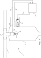
- a test device 1 comprising a chamber 2 which is positioned around and used on sprinkler head 3 of a sprinkler system 4.
- the Sprinkler system comprises a conduit 5 running from a water supply 6 to, amongst others, the sprinkler head 3.
- a pump 7 can be provided for urging the water towards the sprinkler heads and a water meter 8 for measuring the water flow.
- This flow meter can be for instance an induction flow meter.
- a hose 9 is running down towards a drain or a collection tank for inspecting and testing the actual outpouring flow from sprinkler head 3.
- a control unit 10 is connected through a power and control lines 11 to the chamber as is depicted in more detail in figure 2 .
- the Chamber 2 of the testing device 1 can comprise a metal shell and can be mounted on a mobile lifting device 12, such as a fork lift or a mobile crane.
- FIG 2 a detailed view of the testing device 1 is provided.
- the chamber 2 of the testing device 1 is positioned around the sprinkler head 3.
- the sprinkler head 3 is connected to the conduit 5 by means of a T-connector 13.
- the sprinkler head 3 typically comprises a deflector plate 14 and a fuse 15, which fuse holds in place a cap or stopper to seal of the exiting nozzle of the sprinkler head 1 as long as it is not activated.
- the chamber 2 of the testing device 1 comprises in this embodiment a air heater 16, which can be a hot air gun or a hair drier.
- the air heater is powered and regulated by the controller 10 through the power and control line 17.
- the chamber 2 further comprises a temperature sensor 20, which is connected to the controller by control line 21.
- the measured temperature can be used for regulating the temperature and for registering the temperature regime during a test.
- the chamber 2 can further comprise a camera 18 to inspect if the sprinkler 3 indeed is activated and provide a spraying pattern.
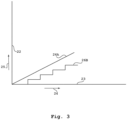
- FIG. 3 A typical test temperature regime is depicted in figure 3 .
- the horizontal axis, the abscissa 23 represents time 24, and the vertical axis, the ordinate 22 represents the temperature 25.
- the line 26 represents the time dependent temperature regime that is used during a test.
- the top wall of the chamber 2 can be comprising a set of inwardly arranged brushes which allow to be fitted around a sprinkler head, yet seal off and isolate the inner part of the chamber 2 as much as possible from the ambient surroundings, while the sprinkler head is penetrating through the brushes.
- Another way may be a resilient foil seal with a central hole and e.g. a resilient reinforcement ring around said hole, for fitting snuggly around the sprinkler head 3 to be tested.
- the temperature control regulated by the sensor 20 controller 10 and the heater 16, used to regulate the temperature may alternatively comprise a small container, configured to fit around the sprinkler head, which container can be filled with a temperature controlled liquid, e.g. a bio-based oil such as vegetable oil or any other suitable liquid or oil.
- a temperature controlled liquid e.g. a bio-based oil such as vegetable oil or any other suitable liquid or oil.
- the oil in the container is slowly heated up, until the fuse will collapse.
Landscapes
- Health & Medical Sciences (AREA)
- Public Health (AREA)
- Business, Economics & Management (AREA)
- Emergency Management (AREA)
- Physics & Mathematics (AREA)
- Engineering & Computer Science (AREA)
- Acoustics & Sound (AREA)
- Signal Processing (AREA)
- Fire-Extinguishing By Fire Departments, And Fire-Extinguishing Equipment And Control Thereof (AREA)
Claims (9)
- Sprinklertestvorrichtung (1) zum Testen, vor Ort, in einem Sprinklersystem (4) selbst, der Funktionalität des Sprinklersystems (4), wobei die tatsächliche eingestellte Temperatur einer Schmelzsicherung des Sprinklerkopfes (3) getestet wird, zusammen mit einem tatsächlichen Durchfluss des Löschmittels am spezifischen Ort des Sprinklerkopfs (3),
dadurch gekennzeichnet, dass die Vorrichtung (1) Folgendes umfasst:- eine Kammer (2) dazu ausgelegt, um einen in einem Sprinklersystem (4) montierten Sprinklerkopf (3) zu passen;- eine Ablassleitung (9) zum Leiten von Löschmittel zu einem Entsorgungs- oder Sammelbehälter; und- einen Temperaturregler (10, 16, 17, 20, 21) zum Regeln der Temperatur in der Kammer (2). - Sprinklertestvorrichtung (1) nach Anspruch 1, wobei der Temperaturregler (10, 16, 17, 20, 21) einen Temperatursensor (20) umfasst, vorzugsweise in der Kammer (3).
- Sprinklertestvorrichtung (1) nach einem der vorhergehenden Ansprüche, wobei der Temperaturregler (10, 16, 17, 20, 21) eine Steuereinheit (10) umfasst.
- Sprinklertestvorrichtung (1) nach einem der vorhergehenden Ansprüche, wobei der Temperaturregler (10, 16, 17, 20, 21) einen Luftheizer umfasst, wie etwa eine Heißluftpistole (16).
- Sprinklertestvorrichtung (1) nach einem der vorhergehenden Ansprüche, wobei der Temperaturregler (10, 16, 17, 20, 21) eine Kamera (18) und/oder eine Kolbenberstregistrierung, z. B. einen akustischen Sensor, umfasst.
- Sprinklertestvorrichtung (1) nach einem der vorhergehenden Ansprüche, wobei die Steuereinheit (10) ausgelegt ist zum Bereitstellen eines zeitabhängigen Temperaturprofils (26) in der Kammer (2).
- Sprinklertestvorrichtung (1) nach einem der vorhergehenden Ansprüche, wobei die Kammer (2) der Testvorrichtung (1) an einer mobilen Anhebevorrichtung montiert ist, wie etwa einem Gabelstapler oder einem mobilen Kran (12).
- Verfahren zum Testen eines Sprinklersystems (4) vor Ort, im Sprinklersystem (4) selbst, der Funktionalität des Sprinklersystems (4), wobei die tatsächliche eingestellte Temperatur einer Schmelzsicherung des Sprinklerkopfes (3) getestet wird, zusammen mit einem tatsächlichen Durchfluss des Löschmittels am spezifischen Ort des Sprinklerkopfs (3),
dadurch gekennzeichnet, dass das Verfahren die folgenden Schritte umfasst, die in einer beliebigen geeigneten Reihenfolge auszuführen sind;a. Bereitstellen einer Sprinklertestvorrichtung (1) nach einem der Ansprüche 1-7;b. Positionieren der Kammer (2) der Sprinklertestvorrichtung (1) um einen ersten Sprinklerkopf (3) eines zu testenden Sprinklersystems (4);c. Regeln der Temperatur um den Sprinklerkopf (3) zu Testzwecken. - Verfahren nach Anspruch 8, wobei, vor Schritt b., eine Hilfspumpe mit dem Sprinklersystem (4) verbunden ist und eine dauerhaft installierte Pumpe (7) des Sprinklersystems (4) von dessen Sprinklerköpfen (3) getrennt ist.
Applications Claiming Priority (2)
| Application Number | Priority Date | Filing Date | Title |
|---|---|---|---|
| NL2022140 | 2018-12-05 | ||
| PCT/NL2019/050807 WO2020117058A1 (en) | 2018-12-05 | 2019-12-04 | Sprinkler test device and method |
Publications (3)
| Publication Number | Publication Date |
|---|---|
| EP3890844A1 EP3890844A1 (de) | 2021-10-13 |
| EP3890844C0 EP3890844C0 (de) | 2024-06-19 |
| EP3890844B1 true EP3890844B1 (de) | 2024-06-19 |
Family
ID=69024569
Family Applications (1)
| Application Number | Title | Priority Date | Filing Date |
|---|---|---|---|
| EP19828341.8A Active EP3890844B1 (de) | 2018-12-05 | 2019-12-04 | Sprinklertestvorrichtung und verfahren |
Country Status (3)
| Country | Link |
|---|---|
| US (1) | US20220032099A1 (de) |
| EP (1) | EP3890844B1 (de) |
| WO (1) | WO2020117058A1 (de) |
Families Citing this family (1)
| Publication number | Priority date | Publication date | Assignee | Title |
|---|---|---|---|---|
| JP7574246B2 (ja) | 2022-07-04 | 2024-10-28 | 株式会社ネクスコ・エンジニアリング新潟 | 流体噴霧測定車両の誘導装置と誘導方法 |
Family Cites Families (9)
| Publication number | Priority date | Publication date | Assignee | Title |
|---|---|---|---|---|
| US6085585A (en) * | 1999-04-19 | 2000-07-11 | Factory Mutual Research Corporation | Sprinkler performance evaluation system |
| KR100443580B1 (ko) * | 2000-09-14 | 2004-08-11 | 건국방재 주식회사 | 스프링클러 헤드 비상장치 |
| US20090188567A1 (en) * | 2008-01-28 | 2009-07-30 | Agf Manufacturing, Inc. | Fire suppression fluid circulation system |
| KR100849941B1 (ko) * | 2008-04-29 | 2008-08-01 | 원우이에프엔지니어링주식회사 | 열 및 연기 화재감지장치 복합시험기 |
| US9345918B2 (en) * | 2012-12-20 | 2016-05-24 | Victaulic Company | Dry sprinkler |
| GB201305239D0 (en) | 2013-03-21 | 2013-05-01 | Paradigm Flow Services Ltd | Water deluge testing apparatus and method |
| US10413766B2 (en) * | 2013-07-12 | 2019-09-17 | Shae Mete | Tool and method for draining a fire sprinkler system and a fire sprinkler |
| US20160059059A1 (en) * | 2014-08-26 | 2016-03-03 | Factory Mutual Insurance Company | Apparatus and method to monitor for fire events and dynamically activate fire sprinklers |
| US10207134B2 (en) | 2014-09-05 | 2019-02-19 | Lund Fire Products Co. Inc. | System and method for testing a fire suppression system |
-
2019
- 2019-12-04 WO PCT/NL2019/050807 patent/WO2020117058A1/en not_active Ceased
- 2019-12-04 US US17/299,919 patent/US20220032099A1/en not_active Abandoned
- 2019-12-04 EP EP19828341.8A patent/EP3890844B1/de active Active
Also Published As
| Publication number | Publication date |
|---|---|
| WO2020117058A1 (en) | 2020-06-11 |
| EP3890844C0 (de) | 2024-06-19 |
| US20220032099A1 (en) | 2022-02-03 |
| EP3890844A1 (de) | 2021-10-13 |
Similar Documents
| Publication | Publication Date | Title |
|---|---|---|
| US7766252B2 (en) | Dry sprinkler assembly | |
| US12311212B2 (en) | Fire suppression system remote monitoring | |
| CA2911790C (en) | Pre-action sprinkler head | |
| US10132786B2 (en) | Method for testing a gas sensor and gas-measuring device with a testing device for testing a gas sensor | |
| CN103354759B (zh) | 消防安全控制系统 | |
| RU2460560C1 (ru) | Установка для тушения пожара | |
| CN112312976B (zh) | 用于带有易碎泡状物的消防喷洒器的裂纹检测功能 | |
| KR101753809B1 (ko) | 건축물의 전기장치를 이용한 소방 개폐 밸브 감지 스위치 | |
| EP3890844B1 (de) | Sprinklertestvorrichtung und verfahren | |
| KR102173033B1 (ko) | 주거용 주방소화 시스템 | |
| EP2714206B1 (de) | Verfahren zur brandbekämpfung und düse mit einem deckel | |
| KR101005253B1 (ko) | 화재감지튜브 부착형 자동소화장치 | |
| US2713916A (en) | Automatic sprinkler system | |
| RU2661858C1 (ru) | Способ регистрации времени срабатывания спринклерного оросителя (варианты) и устройство для его реализации | |
| EP3886997B1 (de) | Fernüberwachung eines feuerunterdrückungssystems | |
| KR102290688B1 (ko) | 실시간 실험실 모니터링 시스템 | |
| EP3170534A1 (de) | Bleiarme sprinkleranlagen für wohngebäude | |
| JP2010063531A (ja) | スプリンクラヘッド及びスプリンクラヘッドの点検方法 | |
| CN101670160A (zh) | 一种电热引爆响应快速的温感式旋转喷淋灭火装置 | |
| RU166375U1 (ru) | Модуль газового пожаротушения | |
| US10317264B1 (en) | Automatic trip test simulator | |
| US1719371A (en) | Chimney-fire extinguisher | |
| RU2471524C1 (ru) | Спринклерный ороситель с управляемым пуском | |
| KR20190094948A (ko) | 천장설치형 자동 스프링클러 소화기 | |
| JP2639880B2 (ja) | 流体の充満確認機能を有するスプリンクラーヘッドとこれを使用した流体の充満確認方法 |
Legal Events
| Date | Code | Title | Description |
|---|---|---|---|
| STAA | Information on the status of an ep patent application or granted ep patent |
Free format text: STATUS: UNKNOWN |
|
| STAA | Information on the status of an ep patent application or granted ep patent |
Free format text: STATUS: THE INTERNATIONAL PUBLICATION HAS BEEN MADE |
|
| PUAI | Public reference made under article 153(3) epc to a published international application that has entered the european phase |
Free format text: ORIGINAL CODE: 0009012 |
|
| STAA | Information on the status of an ep patent application or granted ep patent |
Free format text: STATUS: REQUEST FOR EXAMINATION WAS MADE |
|
| 17P | Request for examination filed |
Effective date: 20210705 |
|
| AK | Designated contracting states |
Kind code of ref document: A1 Designated state(s): AL AT BE BG CH CY CZ DE DK EE ES FI FR GB GR HR HU IE IS IT LI LT LU LV MC MK MT NL NO PL PT RO RS SE SI SK SM TR |
|
| DAV | Request for validation of the european patent (deleted) | ||
| DAX | Request for extension of the european patent (deleted) | ||
| GRAP | Despatch of communication of intention to grant a patent |
Free format text: ORIGINAL CODE: EPIDOSNIGR1 |
|
| STAA | Information on the status of an ep patent application or granted ep patent |
Free format text: STATUS: GRANT OF PATENT IS INTENDED |
|
| INTG | Intention to grant announced |
Effective date: 20240131 |
|
| GRAS | Grant fee paid |
Free format text: ORIGINAL CODE: EPIDOSNIGR3 |
|
| GRAA | (expected) grant |
Free format text: ORIGINAL CODE: 0009210 |
|
| STAA | Information on the status of an ep patent application or granted ep patent |
Free format text: STATUS: THE PATENT HAS BEEN GRANTED |
|
| AK | Designated contracting states |
Kind code of ref document: B1 Designated state(s): AL AT BE BG CH CY CZ DE DK EE ES FI FR GB GR HR HU IE IS IT LI LT LU LV MC MK MT NL NO PL PT RO RS SE SI SK SM TR |
|
| REG | Reference to a national code |
Ref country code: GB Ref legal event code: FG4D |
|
| REG | Reference to a national code |
Ref country code: CH Ref legal event code: EP |
|
| REG | Reference to a national code |
Ref country code: DE Ref legal event code: R096 Ref document number: 602019053962 Country of ref document: DE |
|
| U01 | Request for unitary effect filed |
Effective date: 20240715 |
|
| U07 | Unitary effect registered |
Designated state(s): AT BE BG DE DK EE FI FR IT LT LU LV MT NL PT SE SI Effective date: 20240723 |
|
| PG25 | Lapsed in a contracting state [announced via postgrant information from national office to epo] |
Ref country code: HR Free format text: LAPSE BECAUSE OF FAILURE TO SUBMIT A TRANSLATION OF THE DESCRIPTION OR TO PAY THE FEE WITHIN THE PRESCRIBED TIME-LIMIT Effective date: 20240619 |
|
| PG25 | Lapsed in a contracting state [announced via postgrant information from national office to epo] |
Ref country code: GR Free format text: LAPSE BECAUSE OF FAILURE TO SUBMIT A TRANSLATION OF THE DESCRIPTION OR TO PAY THE FEE WITHIN THE PRESCRIBED TIME-LIMIT Effective date: 20240920 |
|
| PG25 | Lapsed in a contracting state [announced via postgrant information from national office to epo] |
Ref country code: NO Free format text: LAPSE BECAUSE OF FAILURE TO SUBMIT A TRANSLATION OF THE DESCRIPTION OR TO PAY THE FEE WITHIN THE PRESCRIBED TIME-LIMIT Effective date: 20240919 Ref country code: HR Free format text: LAPSE BECAUSE OF FAILURE TO SUBMIT A TRANSLATION OF THE DESCRIPTION OR TO PAY THE FEE WITHIN THE PRESCRIBED TIME-LIMIT Effective date: 20240619 Ref country code: GR Free format text: LAPSE BECAUSE OF FAILURE TO SUBMIT A TRANSLATION OF THE DESCRIPTION OR TO PAY THE FEE WITHIN THE PRESCRIBED TIME-LIMIT Effective date: 20240920 Ref country code: RS Free format text: LAPSE BECAUSE OF FAILURE TO SUBMIT A TRANSLATION OF THE DESCRIPTION OR TO PAY THE FEE WITHIN THE PRESCRIBED TIME-LIMIT Effective date: 20240919 |
|
| PG25 | Lapsed in a contracting state [announced via postgrant information from national office to epo] |
Ref country code: PL Free format text: LAPSE BECAUSE OF FAILURE TO SUBMIT A TRANSLATION OF THE DESCRIPTION OR TO PAY THE FEE WITHIN THE PRESCRIBED TIME-LIMIT Effective date: 20240619 |
|
| PG25 | Lapsed in a contracting state [announced via postgrant information from national office to epo] |
Ref country code: IS Free format text: LAPSE BECAUSE OF FAILURE TO SUBMIT A TRANSLATION OF THE DESCRIPTION OR TO PAY THE FEE WITHIN THE PRESCRIBED TIME-LIMIT Effective date: 20241019 |
|
| PG25 | Lapsed in a contracting state [announced via postgrant information from national office to epo] |
Ref country code: CZ Free format text: LAPSE BECAUSE OF FAILURE TO SUBMIT A TRANSLATION OF THE DESCRIPTION OR TO PAY THE FEE WITHIN THE PRESCRIBED TIME-LIMIT Effective date: 20240619 |
|
| PG25 | Lapsed in a contracting state [announced via postgrant information from national office to epo] |
Ref country code: RO Free format text: LAPSE BECAUSE OF FAILURE TO SUBMIT A TRANSLATION OF THE DESCRIPTION OR TO PAY THE FEE WITHIN THE PRESCRIBED TIME-LIMIT Effective date: 20240619 Ref country code: SK Free format text: LAPSE BECAUSE OF FAILURE TO SUBMIT A TRANSLATION OF THE DESCRIPTION OR TO PAY THE FEE WITHIN THE PRESCRIBED TIME-LIMIT Effective date: 20240619 |
|
| PG25 | Lapsed in a contracting state [announced via postgrant information from national office to epo] |
Ref country code: ES Free format text: LAPSE BECAUSE OF FAILURE TO SUBMIT A TRANSLATION OF THE DESCRIPTION OR TO PAY THE FEE WITHIN THE PRESCRIBED TIME-LIMIT Effective date: 20240619 Ref country code: SM Free format text: LAPSE BECAUSE OF FAILURE TO SUBMIT A TRANSLATION OF THE DESCRIPTION OR TO PAY THE FEE WITHIN THE PRESCRIBED TIME-LIMIT Effective date: 20240619 |
|
| PG25 | Lapsed in a contracting state [announced via postgrant information from national office to epo] |
Ref country code: SM Free format text: LAPSE BECAUSE OF FAILURE TO SUBMIT A TRANSLATION OF THE DESCRIPTION OR TO PAY THE FEE WITHIN THE PRESCRIBED TIME-LIMIT Effective date: 20240619 Ref country code: SK Free format text: LAPSE BECAUSE OF FAILURE TO SUBMIT A TRANSLATION OF THE DESCRIPTION OR TO PAY THE FEE WITHIN THE PRESCRIBED TIME-LIMIT Effective date: 20240619 Ref country code: RO Free format text: LAPSE BECAUSE OF FAILURE TO SUBMIT A TRANSLATION OF THE DESCRIPTION OR TO PAY THE FEE WITHIN THE PRESCRIBED TIME-LIMIT Effective date: 20240619 Ref country code: PL Free format text: LAPSE BECAUSE OF FAILURE TO SUBMIT A TRANSLATION OF THE DESCRIPTION OR TO PAY THE FEE WITHIN THE PRESCRIBED TIME-LIMIT Effective date: 20240619 Ref country code: IS Free format text: LAPSE BECAUSE OF FAILURE TO SUBMIT A TRANSLATION OF THE DESCRIPTION OR TO PAY THE FEE WITHIN THE PRESCRIBED TIME-LIMIT Effective date: 20241019 Ref country code: ES Free format text: LAPSE BECAUSE OF FAILURE TO SUBMIT A TRANSLATION OF THE DESCRIPTION OR TO PAY THE FEE WITHIN THE PRESCRIBED TIME-LIMIT Effective date: 20240619 Ref country code: CZ Free format text: LAPSE BECAUSE OF FAILURE TO SUBMIT A TRANSLATION OF THE DESCRIPTION OR TO PAY THE FEE WITHIN THE PRESCRIBED TIME-LIMIT Effective date: 20240619 |
|
| U20 | Renewal fee for the european patent with unitary effect paid |
Year of fee payment: 6 Effective date: 20241227 |
|
| PLBE | No opposition filed within time limit |
Free format text: ORIGINAL CODE: 0009261 |
|
| STAA | Information on the status of an ep patent application or granted ep patent |
Free format text: STATUS: NO OPPOSITION FILED WITHIN TIME LIMIT |
|
| 26N | No opposition filed |
Effective date: 20250320 |
|
| PG25 | Lapsed in a contracting state [announced via postgrant information from national office to epo] |
Ref country code: MC Free format text: LAPSE BECAUSE OF FAILURE TO SUBMIT A TRANSLATION OF THE DESCRIPTION OR TO PAY THE FEE WITHIN THE PRESCRIBED TIME-LIMIT Effective date: 20240619 |
|
| REG | Reference to a national code |
Ref country code: CH Ref legal event code: PL |
|
| GBPC | Gb: european patent ceased through non-payment of renewal fee |
Effective date: 20241204 |
|
| PG25 | Lapsed in a contracting state [announced via postgrant information from national office to epo] |
Ref country code: GB Free format text: LAPSE BECAUSE OF NON-PAYMENT OF DUE FEES Effective date: 20241204 |
|
| PG25 | Lapsed in a contracting state [announced via postgrant information from national office to epo] |
Ref country code: CH Free format text: LAPSE BECAUSE OF NON-PAYMENT OF DUE FEES Effective date: 20241231 |
|
| PG25 | Lapsed in a contracting state [announced via postgrant information from national office to epo] |
Ref country code: IE Free format text: LAPSE BECAUSE OF NON-PAYMENT OF DUE FEES Effective date: 20241204 |