EP3889984A1 - Schalt- und schutzmittel für eine niederspannungsschalttafel und niederspannungsschaltanlage mit diesen schalt- und schutzmitteln - Google Patents
Schalt- und schutzmittel für eine niederspannungsschalttafel und niederspannungsschaltanlage mit diesen schalt- und schutzmitteln Download PDFInfo
- Publication number
- EP3889984A1 EP3889984A1 EP19842783.3A EP19842783A EP3889984A1 EP 3889984 A1 EP3889984 A1 EP 3889984A1 EP 19842783 A EP19842783 A EP 19842783A EP 3889984 A1 EP3889984 A1 EP 3889984A1
- Authority
- EP
- European Patent Office
- Prior art keywords
- switching
- protection means
- protection
- circuit breaker
- casing
- Prior art date
- Legal status (The legal status is an assumption and is not a legal conclusion. Google has not performed a legal analysis and makes no representation as to the accuracy of the status listed.)
- Granted
Links
Images



Classifications
-
- H—ELECTRICITY
- H01—ELECTRIC ELEMENTS
- H01H—ELECTRIC SWITCHES; RELAYS; SELECTORS; EMERGENCY PROTECTIVE DEVICES
- H01H9/00—Details of switching devices, not covered by groups H01H1/00 - H01H7/00
- H01H9/10—Adaptation for built-in fuses
-
- H—ELECTRICITY
- H01—ELECTRIC ELEMENTS
- H01H—ELECTRIC SWITCHES; RELAYS; SELECTORS; EMERGENCY PROTECTIVE DEVICES
- H01H33/00—High-tension or heavy-current switches with arc-extinguishing or arc-preventing means
- H01H33/60—Switches wherein the means for extinguishing or preventing the arc do not include separate means for obtaining or increasing flow of arc-extinguishing fluid
- H01H33/66—Vacuum switches
- H01H33/666—Operating arrangements
- H01H33/6661—Combination with other type of switch, e.g. for load break switches
-
- H—ELECTRICITY
- H01—ELECTRIC ELEMENTS
- H01H—ELECTRIC SWITCHES; RELAYS; SELECTORS; EMERGENCY PROTECTIVE DEVICES
- H01H31/00—Air-break switches for high tension without arc-extinguishing or arc-preventing means
- H01H31/003—Earthing switches
-
- H—ELECTRICITY
- H01—ELECTRIC ELEMENTS
- H01H—ELECTRIC SWITCHES; RELAYS; SELECTORS; EMERGENCY PROTECTIVE DEVICES
- H01H33/00—High-tension or heavy-current switches with arc-extinguishing or arc-preventing means
- H01H33/60—Switches wherein the means for extinguishing or preventing the arc do not include separate means for obtaining or increasing flow of arc-extinguishing fluid
- H01H33/66—Vacuum switches
- H01H33/666—Operating arrangements
-
- H—ELECTRICITY
- H01—ELECTRIC ELEMENTS
- H01H—ELECTRIC SWITCHES; RELAYS; SELECTORS; EMERGENCY PROTECTIVE DEVICES
- H01H2300/00—Orthogonal indexing scheme relating to electric switches, relays, selectors or emergency protective devices covered by H01H
- H01H2300/018—Application transfer; between utility and emergency power supply
-
- H—ELECTRICITY
- H02—GENERATION; CONVERSION OR DISTRIBUTION OF ELECTRIC POWER
- H02B—BOARDS, SUBSTATIONS OR SWITCHING ARRANGEMENTS FOR THE SUPPLY OR DISTRIBUTION OF ELECTRIC POWER
- H02B1/00—Frameworks, boards, panels, desks, casings; Details of substations or switching arrangements
- H02B1/26—Casings; Parts thereof or accessories therefor
- H02B1/30—Cabinet-type casings; Parts thereof or accessories therefor
- H02B1/32—Mounting of devices therein
- H02B1/34—Racks
- H02B1/36—Racks with withdrawable units
Definitions
- the present invention relates to switching and protection means installed in low-voltage boards, where said boards are in charge of, once the energy has been transformed to the low-voltage range, distributing the electric energy to different consumers.
- the switching and protection means of the invention can replace the well-known fuse block commonly used as a protection element in low-voltage boards.
- the switching and protection means of the invention comprises the functions of both protecting and isolating the low-voltage board from the power source and/or the function of grounding the set of distribution busbars.
- a low-voltage board comprises a metallic or insulating enclosure inside which there are installed different electrical components such as the set of line connection busbars of the board, the distribution busbar, fuse blocks, the switching means comprising the function of isolating the low-voltage board from the power source and/or the function of grounding the set of distribution busbars, as well as the auxiliary and measurement circuit output.
- the purpose of the set of line connection busbars is to electrically connect the conductors coming from the medium-voltage/low-voltage transformer with the distribution busbar, the purpose of the latter being to pass the energy coming from the set of line connection busbars to the different fuse blocks.
- the fuse block has the function of protecting the electrical line suspended from same against overloads and short-circuit currents, i.e., its main function is to open the circuit when there is an electrical fault caused by either an overload or a short-circuit. Therefore, due to an electrical fault caused by an overload or a short-circuit, the fuse melts and the circuit is open, with the line suspended from said fuse block having no voltage circulating in same. Nevertheless, even though the fuse constitutes effective protection means against overloads and short-circuits, this protection means has the drawback concerning the time required to restore voltage in the line affected by the fault, which involves the need to send a skilled operator to the installation where the low-voltage board is located and replace the melted fuse or fuses.
- the maintenance, repair, replacement or expansion tasks on the low-voltage board are carried out after first interrupting, for safety reasons, the service of the board itself, i.e., leaving said low-voltage board out of service, since parts of the board which are live when it is in service need to be accessed.
- the set of busbars must be rendered temporarily unusable in order to interconnect said set of busbars and the busbars of the expansion board.
- To leave the low-voltage board out of service several switching operations must be performed in the installation where said low-voltage board is located.
- low-voltage boards comprise an auxiliary or secondary line connection, which allows the connection of an external auxiliary power source, such as a generator, for example, commonly used when there is a deficit in the generation of electric energy somewhere or when the power supply is cut off, and electric energy can thus be supplied to consumers.
- an external auxiliary power source such as a generator, for example, commonly used when there is a deficit in the generation of electric energy somewhere or when the power supply is cut off, and electric energy can thus be supplied to consumers.
- the auxiliary line connection is integrated in the actual enclosure of the board and in other cases it is integrated in the switching means comprising the function of isolating the low-voltage board from power.
- connection is performed with the board being out of service, i.e., before connecting the external auxiliary power source, the low-voltage board is left out of service, so means capable of isolating the low-voltage board from the power supply grid are required.
- a disconnecting block which is installed in the head of the low-voltage board as an element with respect to the fuse blocks.
- the disconnecting block can be made up of one-pole modules, such that the disconnecting block can be a two-pole, three-pole, or tetra-pole disconnecting block.
- Each one-pole module is generally formed by a casing which partially houses therein one or more input strips and one or more output strips which are respectively connected through their free ends to the power supply and to the distribution busbars of the low-voltage board.
- Coupling or uncoupling means are also housed inside the casing, said means being coupled (disconnecting block closed) or uncoupled (disconnecting block open) with respect to the other end (inside the casing) of the input and output strips for isolating (disconnecting block open) or connecting (disconnecting block closed) the low-voltage board from/to the power supply.
- This disconnecting block is a vertical tetra-pole block with an upper or lower line connection, and forms an interchangeable unit for being assembled in low-voltage boards.
- this disconnecting block incorporates an isolating casing inside of which a vertical tetra-pole disconnector is housed, the input strips of which are formed by busbars that are prolonged until they project through the upper or lower part of the casing to be connected to the power supply of the low-voltage board.
- the addition of the break switch to the low-voltage board involves the drawback that the board must have supporting anchors, electrical connection points, etc., all of which imply larger dimensions of the board, and this affects both the transport thereof and the space for its placement. Furthermore, it involves more assembly tasks, such as, for example, the need to establish more electrical connections, and therefore increasing the risk or the probability of poorly establishing the connections, poor tightening, etc.
- the mentioned low-voltage boards of the state of the art comprise fuse blocks having the function of protecting the electrical line against overloads and short-circuits, and disconnecting blocks for isolating the low-voltage board from the power supply and/or the function of grounding the set of distribution busbars.
- the need to have both elements so as to perform said functions involves the drawback that the low-voltage board acquires dimensions such that in some locations there is not enough space for installing it.
- the low-voltage board in order for the low-voltage board to have a certain degree of protection against accidental contacts with live parts and to be a safe board for operations, additional measures must be applied, such as the placement of intermediate barriers, doors with locks, etc., to prevent direct access to the line connection busbars, to the disconnector, and to the input strips.
- the switching and protection means object of the invention seeks to resolve each and every one of the aforementioned problems.
- Said switching and protection means is for being applied in low-voltage boards comprising at least one set of line connection busbars, a distribution busbar, an auxiliary line connection, auxiliary and measurement circuit outputs, etc.
- the switching and protection means has a first function of protection against electrical faults due to overloads and short-circuits, as well as a second function of isolating the low-voltage board from the power supply and/or the function of grounding the set of distribution busbars. In this way, both functions are thereby allowed to be performed by means of a single element, i.e., the switching and protection means of the invention, instead of using a separate element for carrying out each one of them, thereby obtaining a more compact low-voltage board which prevents the mentioned space problems for installation.
- the switching and protection means comprises at least one switch with at least two positions (making, breaking and/or disconnecting), provided with a fixed contact and a moveable contact.
- This switching and protection means can comprise a vacuum circuit breaker with two positions that can be switched both locally and remotely and have the capacity to break electric currents due to overloads and short-circuits, as well as to open rated or load currents, as established in standard IEC 60947-2:2006, PART 2: CIRCUIT BREAKERS.
- This vacuum circuit breaker also has auto-reclosing capacity for eliminating transient faults, and it will be programmed depending on the time and type of fault and performed from the control unit of the transformer substation.
- the switching and protection means also comprises at least one actuation means, such as for example an actuator with two positions, provided with a first functional position and a second functional position, such that depending on the position of the actuator the switch will perform the function of making or the function of breaking and/or disconnecting, thereby carrying out the functions of protecting against electrical faults due to overloads and short-circuits, and of isolating the low-voltage board from the power supply.
- at least one actuation means such as for example an actuator with two positions, provided with a first functional position and a second functional position, such that depending on the position of the actuator the switch will perform the function of making or the function of breaking and/or disconnecting, thereby carrying out the functions of protecting against electrical faults due to overloads and short-circuits, and of isolating the low-voltage board from the power supply.
- the switching and protection means can also comprise:
- the switch being able to have three positions (making, breaking and/or disconnecting, and grounding), such as, for example, a vacuum circuit breaker with three positions which can be switched both locally and remotely and has the capacity to break electric currents due to overloads and short-circuits, as well as to open rated or load currents, as established in standard IEC 60947-2:2006, PART 2: CIRCUIT BREAKERS, has been contemplated.
- this vacuum circuit breaker has auto-reclosing capacity for the elimination of transient faults, and it will be programmed depending on the time and type of fault and performed from the control unit of the transformer substation.
- the switching and protection means comprises selector means with at least two positions, which allow selecting a first position or a second position manually or in a motorized manner, this selector means being associated with actuation means comprising an actuator provided with a first functional position and a second functional position.
- the switching and protection means with a vacuum circuit breaker with three positions can also comprise:
- the switch of the switching and protection means object of the invention such as a vacuum circuit breaker, for example, can replace the fuses used in the state of the art and therefore the need to replace the melted fuses every time there is an electrical fault due to an overload or short-circuit is prevented. Furthermore, due to the possibility that the switching and protection means of the invention can be switched remotely, the need to send a skilled operator to the installation where the low-voltage board is located to restore service after clearing an electrical fault is avoided.
- the switching and protection means comprises an anti-pump interlock, such that if the opening signal and closing signal of the vacuum circuit breaker are present at the same time, opening will prevail, with the closing being blocked until the switching orders disappear.
- the switching and protection means allows leaving the low-voltage board out of service in an easy, rapid, and safe manner for cases where maintenance, repair, replacement, or expansion tasks must be performed on the low-voltage board, or when it is necessary to connect an external auxiliary power source because of a deficit in the supply of energy, a load transfer, the need to replace the medium-voltage/low-voltage transformer, or the need to perform maintenance or repair tasks in the installations in which the low-voltage board is located.
- the fuse blocks of a field-installed low-voltage board can be replaced entirely or partially with switching and protection means like those of the present invention.
- This re-adaptation of the blocks is possible because the new switching and protection means comprises dimensions and technical characteristics such that it can be installed in the same gap as a fuse block without having to modify any part of the low-voltage board.
- the switching and protection means may comprise, in addition to the vacuum circuit breaker with at least two positions, a protection element protecting against overloads and short-circuit currents installed in series, such as a fuse, for example, such that in this case the switch is a vacuum circuit breaker having fewer features, capable of breaking currents to a certain level and allowing breaking currents higher to the protection element.
- the switching and protection means comprises a casing which can incorporate therein the vacuum circuit breaker with two or three positions, the actuation means, the selector means when it is a vacuum circuit breaker with three positions, and the protection element, such as a fuse, for example.
- the protection element such as a fuse, for example.
- it comprises at least one input strip and one output strip partially incorporated in the casing, where said strips can be electrically connected with the distribution busbar and with the branch conductors outside the casing.
- the connection between the input strips and the distribution busbar and the connection between the output strips and the branch conductors can be of the plug-in type, screw-in type, or of any other type.
- the input strip is attached to the fixed contact of the switch and the output strip is attached to the moveable contact of the same switch by means of an elastic conductor.
- said casing incorporates therein a protection element in series with the vacuum circuit breaker, said casing comprises an access which facilitates replacing the protection element.
- the switching and protection means further comprises a structure which can take in at least one casing provided with at least said actuation means and said switch, where each casing of the switching and protection means can be coupled in said structure through mechanical fixing flanges incorporated both in the structure and in the casing.
- This casing can comprise a grip facilitating its manual or automated coupling/uncoupling with respect to the structure, where this coupling/uncoupling can be carried out with the low-voltage board in service, such that the uncoupling of the casing with respect to the structure entails leaving the switching and protection means in its disconnecting position.
- the structure comprises mechanical protection which prevents contact with the distribution busbar and with the branch conductors once the casing is uncoupled with respect to said structure, thus providing protection for people against the access of dangerous parts and protection for materials against the harmful effects of mechanical impacts.
- the casing of the switching and protection means can comprise a plug-in connection through which the actuator can be powered when said casing is coupled in the structure.
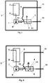
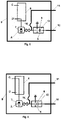
- the switching and protection means (1) of Figures 1 and 2 corresponds to a first embodiment of the invention, wherein said switching and protection means (1) comprises at least one circuit breaker (5) with two positions, making - breaking and/or disconnecting, such as a vacuum circuit breaker, for example.
- the switching and protection means (1) comprises at least one actuation means (6) comprising an actuator with two positions, provided with a first functional position (C) and a second functional position (D).
- This actuation means (6) is associated with the circuit breaker (5) such that the movement of the actuator from its first functional position (C) to its second functional position (D) or vice versa causes the movement of a moveable contact (8) of the circuit breaker (5), leading said moveable contact (8) to be connected with a fixed contact (13) of the switch (5) (making position of the circuit breaker (5)) or leading said moveable contact (8) to separate from the fixed contact (13) (breaking and/or disconnecting position of the circuit breaker (5)).
- Figure 1 corresponds to the making position of the circuit breaker (5)
- Figure 2 corresponds to the breaking and/or disconnecting position of the circuit breaker (5).
- the switching and protection means (1) comprises a casing (9) in which the actuation means (6) and the circuit breaker (5) are incorporated.
- the switching and protection means (1) comprises at least one input strip (10) and one output strip (11) partially incorporated in the casing (9), where said strips (10, 11) can be electrically connected with a distribution busbar (12) and with branch conductors (19), respectively, outside the casing (9).
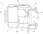
- the connection between the input strips (10) and the distribution busbar (12) and the connection between the output strips (11) and the branch conductors (19) can be of the type plug-in as shown in Figures 7 and 11 , of the screw-in type, or of any other type.
- the input strip (10) is attached to the fixed contact (13) of the circuit breaker (5) and the output strip (11) is attached to the moveable contact (8) of the same circuit breaker (5) by means of an elastic conductor (14).
- the switching and protection means (1) may comprise a structure (15), which can take in at least one casing (9) provided with at least said actuation means (6) and said circuit breaker (5), each casing (9) of the switching and protection means (1) being coupled in said structure (15) through mechanical fixing flanges (16) in both the structure (15) and the casing (9), as shown in Figures 7 and 9 .
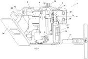
- the casing (9) can comprise a grip (20) facilitating its manual or automated coupling/uncoupling with respect to the structure (15), as shown in Figures 7 , 8 , and 11 , where this coupling/uncoupling can be carried out with the low-voltage board in service, such that the uncoupling of the casing (9) with respect to the structure (15) entails leaving the switching and protection means (1) in its disconnecting position.
- the structure (15) comprises a mechanical protection (21) which prevents contact with the distribution busbar (12) and with the branch conductors (19) once the casing (9) is uncoupled with respect to said structure (15), as shown in Figure 9 .
- the casing (9) of the switching and protection means (1) may comprise a plug-in connection (17) through which the actuation means (6) can be powered when said casing (9) is coupled in the structure (15), as shown in Figure 7 .
- the switching and protection means (1) comprises at least one circuit breaker (5) with three positions (making, breaking and/or disconnecting, and grounding), such as, for example, a vacuum circuit breaker with three positions which can be switched both locally and remotely.
- the switching and protection means (1) comprises selector means (7) with at least two positions, which allows selecting a first position (A) or a second position (B) manually or in a motorized manner, this selector means (7) being associated with actuation means (6) which can comprise, for example, an actuator provided with a first functional position (C) and a second functional position (D).
- the switching and protection means (1) also comprises a casing (9) in which the circuit breaker (5), the actuation means (6), and the selector means (7) are incorporated, as shown in Figures 3-8 and 11 .
- the switching and protection means (1) comprises at least one input strip (10) and one output strip (11) partially incorporated in the casing (9), where said strips (10, 11) can be electrically connected with the distribution busbar (12) and with the branch conductors (19), respectively, outside the casing (9).
- the connection between the input strips (10) and the distribution busbar (12) and the connection between the output strips (11) and the branch conductors (19) can be of the type plug-in as shown in Figures 7 and 11 , screw-in type, or of any other type.
- the input strip (10) is attached to the fixed contact (13) of the circuit breaker (5) and the output strip (11) is attached to the moveable contact (8) of the same circuit breaker (5) by means of an elastic conductor (14).
- the switching and protection means (1) can comprise a structure (15) which can take in at least one casing (9) provided with at least said actuation means (6), selector means (7), and circuit breaker (5), where each casing (9) of the switching and protection means (1) can be coupled in said structure (15) through mechanical fixing flanges (16) in both the structure (15) and the casing (9).
- the casing (9) can comprise a grip (20) facilitating its manual or automated coupling/uncoupling with respect to the structure (15), where this coupling/uncoupling can be carried out with the low-voltage board in service, such that the uncoupling of the casing (9) with respect to the structure (15) entails leaving the switching and protection means (1) in its disconnecting position.
- the structure (15) can comprise a mechanical protection (21) which prevents contact with the distribution busbar (12) and with the branch conductors (19) once the casing (9) is uncoupled with respect to said structure (15), as shown in Figure 9 .
- the casing (9) of the switching and protection means (1) may comprise a plug-in connection (17) through which the actuator (6) can be powered when said casing (9) is coupled in the structure (15), as shown in Figure 7 .
- the switching and protection means (1) can comprise a protection element (22), such as a fuse, for example, protecting against overloads and short-circuit currents, installed in series with said vacuum circuit breaker (5), such that in this case the circuit breaker (5) is a vacuum circuit breaker having fewer features, capable of breaking currents to a certain level and allowing breaking currents higher to the protection element (22).
- a protection element such as a fuse, for example, protecting against overloads and short-circuit currents
- the switching and protection means (1) comprises also a casing (9) in which the circuit breaker (5), the actuation means (6), and the protection element (22) are incorporated, as shown in Figure 12 .
- the switching and protection means (1) comprises at least one input strip (10) and one output strip (11) partially incorporated in the casing (9), where said strips (10, 11) can be electrically connected with the distribution busbar (12) and with the branch conductors (19), respectively, outside the casing (9).
- the connection between the input strips (10) and the distribution busbar (12) and the connection between the output strips (11) and the branch conductors (19) can be of the plug-in type as shown in Figure 12 , screw-in type, or of any other type.
- the input strip (10) is attached to the fixed contact (13) of the circuit breaker (5) and the output strip (11) is attached to the moveable contact (8) of the same circuit breaker (5) by means of an elastic conductor (14).
- the casing (9) comprises an access (34) which allows replacing the protection element (22) when needed, as shown in Figure 12 , where this access (34) can be a hinged lid, for example.
- the switching and protection means (1) can comprise a structure (15) which can take in at least one casing (9) provided with at least said actuation means (6), the circuit breaker (5), and the protection element (22), where each casing (9) of the switching and protection means (1) can be coupled in said structure (15) through mechanical fixing flanges (16) in both the structure (15) and the casing (9).
- the casing (9) can comprise a grip (20) facilitating its manual or automated coupling/uncoupling with respect to the structure (15), where this coupling/uncoupling can be carried out with the low-voltage board in service, such that the uncoupling of the casing (9) with respect to the structure (15) entails leaving the switching and protection means (1) in its disconnecting position.
- the structure (15) can comprise a mechanical protection (21) which prevents contact with the distribution busbar (12) and with the branch conductors (19) once the casing (9) is uncoupled with respect to said structure (15), as shown in Figure 9 .
- the casing (9) of the switching and protection means (1) may comprise a plug-in connection (17) through which the actuation means (6) can be powered when said casing (9) is coupled in the structure (15), as shown in Figure 12 .
- the switching and protection means (1) can comprise:
Landscapes
- Gas-Insulated Switchgears (AREA)
- Emergency Protection Circuit Devices (AREA)
- Switch Cases, Indication, And Locking (AREA)
Applications Claiming Priority (2)
| Application Number | Priority Date | Filing Date | Title |
|---|---|---|---|
| ES201831157A ES2763627B2 (es) | 2018-11-29 | 2018-11-29 | Medio de maniobra y protección para cuadro de baja tensión y cuadro de baja tensión que incorpora dicho medio de maniobra y protección |
| PCT/ES2019/070803 WO2020109640A1 (es) | 2018-11-29 | 2019-11-26 | Medio de maniobra y protección para cuadro de baja tensión y cuadro de baja tensión que incorpora dicho medio de maniobra y protección |
Publications (3)
| Publication Number | Publication Date |
|---|---|
| EP3889984A1 true EP3889984A1 (de) | 2021-10-06 |
| EP3889984C0 EP3889984C0 (de) | 2025-12-31 |
| EP3889984B1 EP3889984B1 (de) | 2025-12-31 |
Family
ID=69232864
Family Applications (1)
| Application Number | Title | Priority Date | Filing Date |
|---|---|---|---|
| EP19842783.3A Active EP3889984B1 (de) | 2018-11-29 | 2019-11-26 | Schalt- und schutzmittel für niederspannungsverteiler und niederspannungsverteiler mit einem derartigen schalt- und schutzmittel |
Country Status (4)
| Country | Link |
|---|---|
| EP (1) | EP3889984B1 (de) |
| CN (1) | CN113168981A (de) |
| ES (2) | ES2763627B2 (de) |
| WO (1) | WO2020109640A1 (de) |
Cited By (1)
| Publication number | Priority date | Publication date | Assignee | Title |
|---|---|---|---|---|
| WO2023041828A1 (es) * | 2021-09-14 | 2023-03-23 | Ormazabal Y Cia., S.L.U. | Base tripolar automatizada con dispositivo de maniobra y protección para cuadro de baja tensión y cuadro de baja tensión que incorpora dicha base tripolar automatizada |
Families Citing this family (4)
| Publication number | Priority date | Publication date | Assignee | Title |
|---|---|---|---|---|
| GB201911565D0 (en) * | 2019-08-13 | 2019-09-25 | Schneider Electric Ltd | Current management device and voltage distribution unit |
| ES1243729Y1 (es) | 2020-02-19 | 2021-04-28 | Quijada Pablo Paunero | Dispositivo de seguridad y base tripolar |
| CN114123004B (zh) * | 2021-11-30 | 2024-04-12 | 广东电网有限责任公司东莞供电局 | 一种发电快接装置并入箱变装置 |
| CN118645403A (zh) * | 2024-06-20 | 2024-09-13 | 南腾能源集团有限公司 | 一种低压开关断路器 |
Family Cites Families (12)
| Publication number | Priority date | Publication date | Assignee | Title |
|---|---|---|---|---|
| EP0670581A1 (de) * | 1994-03-04 | 1995-09-06 | Weber Ag | Als Schubeinsatz ausgebildeter Sicherungs-Lastschalter |
| CN2316719Y (zh) * | 1997-11-28 | 1999-04-28 | 张帆 | 低压真空断路器 |
| ES2277729B1 (es) | 2005-04-04 | 2008-06-01 | Pronutec, S.A. | Base de seccionamiento tetrapolar vertical. |
| US7186942B1 (en) * | 2006-02-23 | 2007-03-06 | Eaton Corporation | Three-position vacuum interrupter disconnect switch providing current interruption, disconnection and grounding |
| ITMI20062161A1 (it) * | 2006-11-10 | 2008-05-11 | Vei Power Distrib S P A | Apparecchiature tripolare per uno scomparto in media o alta tensione e relativo scomparto comprendente tale apparecchiatura tripolare |
| US7724489B2 (en) * | 2007-08-18 | 2010-05-25 | Ema Electromecanica S.A. | Circuit breaker with high speed mechanically-interlocked grounding switch |
| US8467166B2 (en) * | 2007-08-18 | 2013-06-18 | Ema Electromechanics, Llc | Circuit breaker with high-speed mechanically interlocked impedance grounding switch |
| US9070517B2 (en) * | 2012-08-13 | 2015-06-30 | Electro-Mechanical Corporation | Vacuum interrupter and linear disconnect switch |
| US20170004948A1 (en) * | 2013-03-13 | 2017-01-05 | Google Inc. | Electrical circuit protector |
| DE102014104541B4 (de) * | 2014-03-31 | 2025-11-13 | Schneider Electric Industries Sas | Schaltfeld |
| DE102015106867A1 (de) * | 2015-05-04 | 2016-11-10 | Fritz Driescher KG Spezialfabrik für Elektrizitätswerksbedarf GmbH & Co. | Auslösung eines Erdungsschalters einer Schaltanlage |
| WO2017168429A1 (en) * | 2016-03-30 | 2017-10-05 | Surendran Narayanan | Integrated over load and earth fault protection system for low voltage |
-
2018
- 2018-11-29 ES ES201831157A patent/ES2763627B2/es active Active
-
2019
- 2019-11-26 ES ES19842783T patent/ES3059310T3/es active Active
- 2019-11-26 EP EP19842783.3A patent/EP3889984B1/de active Active
- 2019-11-26 CN CN201980078465.XA patent/CN113168981A/zh active Pending
- 2019-11-26 WO PCT/ES2019/070803 patent/WO2020109640A1/es not_active Ceased
Cited By (1)
| Publication number | Priority date | Publication date | Assignee | Title |
|---|---|---|---|---|
| WO2023041828A1 (es) * | 2021-09-14 | 2023-03-23 | Ormazabal Y Cia., S.L.U. | Base tripolar automatizada con dispositivo de maniobra y protección para cuadro de baja tensión y cuadro de baja tensión que incorpora dicha base tripolar automatizada |
Also Published As
| Publication number | Publication date |
|---|---|
| EP3889984C0 (de) | 2025-12-31 |
| ES3059310T3 (en) | 2026-03-19 |
| ES2763627B2 (es) | 2021-07-01 |
| ES2763627A1 (es) | 2020-05-29 |
| WO2020109640A1 (es) | 2020-06-04 |
| CN113168981A (zh) | 2021-07-23 |
| EP3889984B1 (de) | 2025-12-31 |
Similar Documents
| Publication | Publication Date | Title |
|---|---|---|
| EP3889984B1 (de) | Schalt- und schutzmittel für niederspannungsverteiler und niederspannungsverteiler mit einem derartigen schalt- und schutzmittel | |
| KR101343512B1 (ko) | 개별적으로 차단가능한 기능영역을 갖는 배전 시스템 | |
| EP2600363B1 (de) | Verbindungsvorrichtung für umspannstationsmodule | |
| US9576751B1 (en) | Motorized vacuum isolation switch | |
| EP3195338B1 (de) | Stromverwaltungsvorrichtung | |
| KR100990736B1 (ko) | 보호 배전반의 상태를 감시하고 제어하는 보호 시스템 | |
| CN115425567B (zh) | 一种高安全的sf6全绝缘紧凑型环网柜 | |
| WO2014201475A1 (en) | Ring main unit | |
| EP4404229B1 (de) | Automatisierte dreipolige basis mit schalt- und schutzvorrichtung für niederspannungsschaltfeld und niederspannungsschaltfeld mit der automatisierten dreipoligen basis | |
| KR200262224Y1 (ko) | 3상 지상변압기용 2차측 케이블의 소손 방지구조 | |
| KR101008234B1 (ko) | 접지가 형성된 특별고압 수변전설비 | |
| JP2019103343A (ja) | スイッチギヤおよびスイッチギヤの操作方法 | |
| Arana et al. | FIRST STEPS TOWARDS LV NETWORK AUTOMATION SOLUTIONS | |
| Blower et al. | Trends in distribution transformer protection | |
| Harris et al. | Ring main distribution switchgear-latest trends in use, control and operation | |
| Cardoso | Development of the power system protection: low voltage switchgear MNS | |
| Mackay et al. | Distribution system protection-the application of modular electronic schemes | |
| Biasse et al. | Medium voltage switch-fuse combinations are still well fitting with smartgrid deployment | |
| Blower | New technology for secondary distribution systems | |
| HK1234201B (en) | Current management device | |
| HK1234201A1 (en) | Current management device | |
| Serve et al. | Impact of medium voltage switchgear technology on operating modes in the network | |
| Circuit-breaker | Chapter H LV switchgear: functions & selection | |
| Klaus et al. | The sectionalising circuit-breaker-a means for high-speed feeder automation | |
| Hosan | Study of substation and the protection |
Legal Events
| Date | Code | Title | Description |
|---|---|---|---|
| STAA | Information on the status of an ep patent application or granted ep patent |
Free format text: STATUS: UNKNOWN |
|
| STAA | Information on the status of an ep patent application or granted ep patent |
Free format text: STATUS: THE INTERNATIONAL PUBLICATION HAS BEEN MADE |
|
| PUAI | Public reference made under article 153(3) epc to a published international application that has entered the european phase |
Free format text: ORIGINAL CODE: 0009012 |
|
| STAA | Information on the status of an ep patent application or granted ep patent |
Free format text: STATUS: REQUEST FOR EXAMINATION WAS MADE |
|
| 17P | Request for examination filed |
Effective date: 20210520 |
|
| AK | Designated contracting states |
Kind code of ref document: A1 Designated state(s): AL AT BE BG CH CY CZ DE DK EE ES FI FR GB GR HR HU IE IS IT LI LT LU LV MC MK MT NL NO PL PT RO RS SE SI SK SM TR |
|
| DAV | Request for validation of the european patent (deleted) | ||
| DAX | Request for extension of the european patent (deleted) | ||
| STAA | Information on the status of an ep patent application or granted ep patent |
Free format text: STATUS: EXAMINATION IS IN PROGRESS |
|
| 17Q | First examination report despatched |
Effective date: 20231222 |
|
| GRAP | Despatch of communication of intention to grant a patent |
Free format text: ORIGINAL CODE: EPIDOSNIGR1 |
|
| STAA | Information on the status of an ep patent application or granted ep patent |
Free format text: STATUS: GRANT OF PATENT IS INTENDED |
|
| INTG | Intention to grant announced |
Effective date: 20250820 |
|
| GRAS | Grant fee paid |
Free format text: ORIGINAL CODE: EPIDOSNIGR3 |
|
| GRAA | (expected) grant |
Free format text: ORIGINAL CODE: 0009210 |
|
| STAA | Information on the status of an ep patent application or granted ep patent |
Free format text: STATUS: THE PATENT HAS BEEN GRANTED |
|
| AK | Designated contracting states |
Kind code of ref document: B1 Designated state(s): AL AT BE BG CH CY CZ DE DK EE ES FI FR GB GR HR HU IE IS IT LI LT LU LV MC MK MT NL NO PL PT RO RS SE SI SK SM TR |
|
| REG | Reference to a national code |
Ref country code: CH Ref legal event code: F10 Free format text: ST27 STATUS EVENT CODE: U-0-0-F10-F00 (AS PROVIDED BY THE NATIONAL OFFICE) Effective date: 20251231 Ref country code: GB Ref legal event code: FG4D |
|
| REG | Reference to a national code |
Ref country code: DE Ref legal event code: R096 Ref document number: 602019079906 Country of ref document: DE |
|
| REG | Reference to a national code |
Ref country code: CH Ref legal event code: R17 Free format text: ST27 STATUS EVENT CODE: U-0-0-R10-R17 (AS PROVIDED BY THE NATIONAL OFFICE) Effective date: 20260116 |
|
| REG | Reference to a national code |
Ref country code: IE Ref legal event code: FG4D |
|
| U01 | Request for unitary effect filed |
Effective date: 20260113 |
|
| U07 | Unitary effect registered |
Designated state(s): AT BE BG DE DK EE FI FR IT LT LU LV MT NL PT RO SE SI Effective date: 20260126 |
|
| REG | Reference to a national code |
Ref country code: ES Ref legal event code: FG2A Ref document number: 3059310 Country of ref document: ES Kind code of ref document: T3 Effective date: 20260319 |
|
| PG25 | Lapsed in a contracting state [announced via postgrant information from national office to epo] |
Ref country code: NO Free format text: LAPSE BECAUSE OF FAILURE TO SUBMIT A TRANSLATION OF THE DESCRIPTION OR TO PAY THE FEE WITHIN THE PRESCRIBED TIME-LIMIT Effective date: 20260331 |
|
| PG25 | Lapsed in a contracting state [announced via postgrant information from national office to epo] |
Ref country code: HR Free format text: LAPSE BECAUSE OF FAILURE TO SUBMIT A TRANSLATION OF THE DESCRIPTION OR TO PAY THE FEE WITHIN THE PRESCRIBED TIME-LIMIT Effective date: 20251231 |
|
| PG25 | Lapsed in a contracting state [announced via postgrant information from national office to epo] |
Ref country code: RS Free format text: LAPSE BECAUSE OF FAILURE TO SUBMIT A TRANSLATION OF THE DESCRIPTION OR TO PAY THE FEE WITHIN THE PRESCRIBED TIME-LIMIT Effective date: 20260331 |