EP4404229B1 - Automatisierte dreipolige basis mit schalt- und schutzvorrichtung für niederspannungsschaltfeld und niederspannungsschaltfeld mit der automatisierten dreipoligen basis - Google Patents
Automatisierte dreipolige basis mit schalt- und schutzvorrichtung für niederspannungsschaltfeld und niederspannungsschaltfeld mit der automatisierten dreipoligen basis Download PDFInfo
- Publication number
- EP4404229B1 EP4404229B1 EP22800721.7A EP22800721A EP4404229B1 EP 4404229 B1 EP4404229 B1 EP 4404229B1 EP 22800721 A EP22800721 A EP 22800721A EP 4404229 B1 EP4404229 B1 EP 4404229B1
- Authority
- EP
- European Patent Office
- Prior art keywords
- switching
- automated
- protection device
- disconnector
- circuit breaker
- Prior art date
- Legal status (The legal status is an assumption and is not a legal conclusion. Google has not performed a legal analysis and makes no representation as to the accuracy of the status listed.)
- Active
Links
Images


Classifications
-
- H—ELECTRICITY
- H01—ELECTRIC ELEMENTS
- H01H—ELECTRIC SWITCHES; RELAYS; SELECTORS; EMERGENCY PROTECTIVE DEVICES
- H01H33/00—High-tension or heavy-current switches with arc-extinguishing or arc-preventing means
- H01H33/60—Switches wherein the means for extinguishing or preventing the arc do not include separate means for obtaining or increasing flow of arc-extinguishing fluid
- H01H33/66—Vacuum switches
- H01H33/666—Operating arrangements
- H01H33/6661—Combination with other type of switch, e.g. for load break switches
-
- H—ELECTRICITY
- H01—ELECTRIC ELEMENTS
- H01H—ELECTRIC SWITCHES; RELAYS; SELECTORS; EMERGENCY PROTECTIVE DEVICES
- H01H33/00—High-tension or heavy-current switches with arc-extinguishing or arc-preventing means
- H01H33/60—Switches wherein the means for extinguishing or preventing the arc do not include separate means for obtaining or increasing flow of arc-extinguishing fluid
- H01H33/66—Vacuum switches
- H01H33/666—Operating arrangements
-
- H—ELECTRICITY
- H01—ELECTRIC ELEMENTS
- H01H—ELECTRIC SWITCHES; RELAYS; SELECTORS; EMERGENCY PROTECTIVE DEVICES
- H01H9/00—Details of switching devices, not covered by groups H01H1/00 - H01H7/00
- H01H9/10—Adaptation for built-in fuses
-
- H—ELECTRICITY
- H02—GENERATION; CONVERSION OR DISTRIBUTION OF ELECTRIC POWER
- H02B—BOARDS, SUBSTATIONS OR SWITCHING ARRANGEMENTS FOR THE SUPPLY OR DISTRIBUTION OF ELECTRIC POWER
- H02B1/00—Frameworks, boards, panels, desks, casings; Details of substations or switching arrangements
- H02B1/18—Disposition or arrangement of fuses
-
- H—ELECTRICITY
- H02—GENERATION; CONVERSION OR DISTRIBUTION OF ELECTRIC POWER
- H02B—BOARDS, SUBSTATIONS OR SWITCHING ARRANGEMENTS FOR THE SUPPLY OR DISTRIBUTION OF ELECTRIC POWER
- H02B1/00—Frameworks, boards, panels, desks, casings; Details of substations or switching arrangements
- H02B1/20—Bus-bar or other wiring layouts, e.g. in cubicles, in switchyards
- H02B1/21—Bus-bar arrangements for rack-mounted devices with withdrawable units
-
- H—ELECTRICITY
- H01—ELECTRIC ELEMENTS
- H01H—ELECTRIC SWITCHES; RELAYS; SELECTORS; EMERGENCY PROTECTIVE DEVICES
- H01H2300/00—Orthogonal indexing scheme relating to electric switches, relays, selectors or emergency protective devices covered by H01H
- H01H2300/018—Application transfer; between utility and emergency power supply
-
- H—ELECTRICITY
- H02—GENERATION; CONVERSION OR DISTRIBUTION OF ELECTRIC POWER
- H02B—BOARDS, SUBSTATIONS OR SWITCHING ARRANGEMENTS FOR THE SUPPLY OR DISTRIBUTION OF ELECTRIC POWER
- H02B1/00—Frameworks, boards, panels, desks, casings; Details of substations or switching arrangements
- H02B1/015—Boards, panels, desks; Parts thereof or accessories therefor
- H02B1/04—Mounting thereon of switches or of other devices in general, the switch or device having, or being without, casing
- H02B1/056—Mounting on plugboards
Definitions
- the present invention relates to an automated three-pole base with at least one switching and protection device that is installed in low-voltage switchboards, wherein said switchboards are responsible for, once the energy has been transformed to the low-voltage range, distributing electricity to the different consumers.
- the automated three-pole base with at least one switching and protection device of the invention can replace the known fuse-holder base used as a means of protection in low-voltage switchboards.
- the switching and protection device includes both the protection function and that of isolating the low-voltage switchboard from the part of the low-voltage grid that is downstream the switching and protection device, as well as the grounding function of said low-voltage grid that is downstream the switching and protection device.
- a low-voltage switchboard comprises a metallic or insulating enclosure inside which the different electrical components are installed, such as the set of connection bars for the switchboard, the distribution busbar, the fuse-holder bases, the switching means that includes the function of isolating the low voltage switchboard from the power supply (part of the grid that is upstream of the low voltage switchboard) and/or the grounding function of the set of distribution bars, as well as the output of auxiliary circuits and metering.
- the set of connection bars has the function of electrically connecting the conductors coming from the medium voltage/low voltage transformer with the distribution busbar, the latter's function being to pass the energy coming from the set of connection bars to the different fuse-holder bases.
- the fuse-holder base has the function of protecting the electrical line that hangs from it from overloads and short-circuit currents, that is, its main function is to open the circuit when there is an electrical fault either due to overload or short-circuit. Therefore, due to an electrical fault as a result of overload or short circuit, the fuse blows and the circuit remains open, leaving the line hanging from said fuse-holder base without voltage.
- this means of protection has the inconvenience related to the time required to replenish the voltage on the line affected by the fault, which implies the need to send a qualified operator to the installation where the low voltage switchboard is located and replace the blown fuse or fuses.
- Tasks for maintenance, repair, replacement or extension of the low voltage switchboard are carried out by first interrupting, for safety reasons, the operation of the entire switchboard itself, that is, leaving said low voltage switchboard out of operation, since it is necessary to access parts of the switchboard that in operation are under voltage, such as the busbar set in an extension operation, to make the interconnection between said busbar set and the bars of the extension switchboard.
- To leave the low voltage switchboard out of operation it is necessary to carry out several operations on the installation where said low voltage switchboard is located.
- the medium-voltage/low-voltage transformer must first be disconnected, then disconnecting upstream the switchboard and downstream it must be carried out, leaving thus the switchboard without power, and then the busbar set must be grounded.
- low voltage switchboards include an auxiliary or relief connection, which allows the connection of an external auxiliary power source, such as a generator set, commonly used when there is a deficit in the generation of electrical energy somewhere or when an outage occurs in the electricity supply, and thus be able to supply electricity to consumers.
- an external auxiliary power source such as a generator set
- the auxiliary connection is integrated into the switchboard enclosure itself and in other cases it is integrated into the switching means that includes the function of isolating the low voltage switchboard from the power supply.
- a disconnection base that is installed at the head of the low voltage switchboard as an additional element to the fuse-holder bases.
- the disconnection base can be assembled by one-pole modules, so that the disconnection base can be two-pole, three-pole or fourth-pole.
- Each one-pole module is generally composed of a casing that partially houses one or more input strips and one or more output strips that, through their free ends, are respectively connected to the power supply and to the distribution busbars of the low voltage switchboard.
- Coupling or decoupling means are also housed inside the casing, usually metal blades, which are coupled (closed disconnector) or decoupled (open disconnector) with respect to the other end (inside the casing) of the input and output strips to isolate (open disconnector) or connect (closed disconnector) the low voltage switchboard from the power supply.
- This disconnection base refers to a vertical four-pole base with top or bottom connection, and forms an interchangeable unit for assembly in low voltage switchboards.
- this disconnection base incorporates an insulating casing inside which a vertical four-pole disconnector is housed, the input strips of which are made up of conductive bars that extend until they protrude from the top or bottom of the casing for connection to the power supply of the low voltage switchboard.
- the disconnection base that is installed at the head of the low voltage switchboard can only isolate the low voltage switchboard from the power supply, that is, from the part of the grid that it is upstream the low-voltage switchboard, but not from the low-voltage grid that is downstream the low-voltage switchboard.
- there are no specific means for grounding the low-voltage grid downstream the low-voltage switchboard so when carrying out tasks of maintenance, repair, replacement, etc., on the low-voltage switchboard or on the output lines of the low-voltage switchboard, there is a risk that there may be a possible voltage return from downstream the low-voltage switchboard, which means carrying out the work in an unsafe manner with risk of electrocution for operators.
- document ES1243729U can also be cited, which lacks the isolation and grounding functions of the low-voltage grid that is downstream the low-voltage switchboard.
- the three switching positions or functions (making, breaking and/or disconnecting and grounding) of the vacuum circuit breaker are achieved.
- These examples have the drawback that it is necessary to use vacuum circuit breaker with higher performance, higher cost and larger dimensions, due to their three switching positions, as well as the need to use a selector means to be able to obtain by means of a single two-position operating means the three switching positions of the vacuum circuit breaker, which means that the switching and protection means has larger dimensions and consequently it is more complicated to replace in current low voltage switchboards the well-known fuse-holder base without having to modify any part of the low voltage switchboard.
- the automated three-pole base with at least one switching and protection device according to claim 1 object of the invention intends to solve any and all the aforementioned problems.
- Said automated three-pole base with at least one switching and protection device is applicable to low-voltage switchboards that comprise, at least, a set of connection busbars, a distribution busbar, an auxiliary connection, outputs of auxiliary circuit and metering, etc.
- the switching and protection device includes the function of protection against electrical faults resulting from overloads and short circuits, as well as the function of isolating the low voltage switchboard from the low-voltage grid that is downstream the switching and protection device and/or the function of grounding said low-voltage grid that is downstream the switching and protection device.
- the switching and protection device includes the function of protection against electrical faults resulting from overloads and short circuits, as well as the function of isolating the low voltage switchboard from the low-voltage grid that is downstream the switching and protection device and/or the function of grounding said low-voltage grid that is downstream the switching and protection device.
- this vacuum circuit breaker includes fast reclosing capacity (no need to wait a time between different breaking operations, that is, there is no thermal effect as for example in magneto-thermal switches), it can be manual or automatic reclosing, for the elimination of transient faults, which will be programmed depending on the time and type of fault, and carried out from a control unit of the installation.
- the switching and protection device also comprises at least one first actuation means of the vacuum circuit breaker, such as a mechanical actuator, so that it activates the vacuum circuit breaker to cause said switch to pass from a closed status to an open status and vice versa, thus fulfilling the protection functions, breaking electrical currents due to overloads and short circuits, as well as nominal or load currents, without the need for an auxiliary power supply.
- the switching and protection device also comprises:
- the circuit breaker of the switching and protection device object of the invention can replace the fuses used in the state of the art and therefore the need to replace blown fuses is avoided every time there is an electrical fault due to an overload or short circuit.
- the switching and protection device of the invention can be operated remotely, the need to send a qualified operator to the installation where the low voltage switchboard is located to restore operation after clearing an electrical fault is avoided.
- a backup protection is maintained by means of the protection element (such as a fuse) in series with the circuit breaker.
- the protection element will act (if it is a fuse, it will blow) when the short-circuit level is high enough so as not to allow rapid automatic reclosing, since in the event of high electrical fault levels it is recommended to inspect the installation on site for security reasons.
- the switch is a vacuum circuit breaker with lower performance, capable of breaking currents up to a certain level and allowing the protection element to break greater currents.
- the disconnector comprises linearly sliding contacts, the switching and protection device being able to comprise a second actuation means that acts on the disconnector contacts to cause said disconnector to pass from a closed status to an open status and vice versa.
- the second actuation means can comprise a rack mechanism, provided, for example, with at least one pinion and a toothed bar, such that a rotation applied to the pinion causes the linear displacement of the toothed bar and, in turn, the linear displacement of the moving contact with respect to of the fixed contact of the disconnector.
- the actuation of the second actuation means can be generated, for example, by means of an opening/closing lever, manually or in a motorized way.
- the disconnector can also include a grounding means, so that once the opening switching position of the disconnector is obtained, the part that remains downstream the switching and protection device, specifically the part that remains downstream the disconnector, can be grounded against a possible voltage return from downstream to the low voltage switchboard, thus guaranteeing the safety of operators while they carry out maintenance, repair or replacement tasks on said part downstream the switching and protection device.
- the disconnector can also include a point to be able to safely verify the presence of voltage and to be able to connect to protective ground the downstream connection, such as for maintenance tasks under safe conditions, such as checking the trigger chain and protection of the circuit breaker without affecting the connected / disconnected lines.
- the switching and protection device comprises a casing that can incorporate inside the two-position vacuum circuit breaker, the first actuation means, the disconnector and the second actuation means, being able to leave the protection element mounted on the outside of the casing in a hole provided for this purpose, so that the protection element can be accessible from the outside of the casing and easily replaceable in operation (without the need to leave the low voltage switchboard out of operation).
- a compact switching and protection device is available, which includes several functions instead of using an element to perform each of the functions.
- the casing comprises at least one handle for insertion (manual or automated) of the switching and protection device in a three-pole enclosure or for removal (manual or automated) of said device from a three-pole enclosure, said three-pole enclosure being able to include up to three switching and protection devices, one for each phase.
- this three-pole enclosure can be mounted on a support or plinth (which allows connecting a low-voltage switchboard distribution busbar with bypass conductors of the switchboard output), thus obtaining an automated three-pole base equipped with three switching and protection devices, one for each phase.
- the three-pole fuse-holder bases of the state of the art of a low-voltage switchboard installed in the field and in operation can be totally or partially replaced by automated three-pole bases with switching and protection devices such as the one of the present invention, allowing the coexistence of both protection systems in the same low voltage switchboard in operation.
- This re-fitting of the bases is possible because the new automated three-pole base with at least one switching and protection device has such dimensions and technical features that it can be installed in the same hole as a fuse-holder base without having to modify any part of the low voltage switchboard.
- the low voltage switchboard can be left out of operation in an easy, fast and safe way for cases where maintenance, repair, replacement or extension of the low-voltage switchboard needs to be carried out, or when it is necessary to connect an external auxiliary power supply due to a deficit in power supply, a transfer of load, the need to replace the medium voltage / low voltage transformer or the need to carry out maintenance or repair work on the installations where the low voltage switchboard is located or in the lines downstream the low voltage switchboard.
- the switching and protection device can also be safely removed from the three-pole enclosure for maintenance, verification and/or replacement of the protection element, such as a fuse, as well as replacement of the circuit breaker.
- the switching and protection device can be removed from the three-pole enclosure with the low voltage switchboard in operation, without interfering with the operation of the rest of the lines or three-pole bases, maintaining safety and the degree of protection.
- the switching and protection device comprises at least one input terminal and one output terminal at least partially incorporated in the casing, said terminals being able to be electrically connected at one of their ends to a distribution busbar of the low voltage switchboard and with some bypass conductors (of the lines downstream the switching and protection device) externally to the casing, and said terminals may be electrically connected at the other end with the protection element and the disconnector.
- the electrical connection between the input terminal and the distribution busbar and the electrical connection between the output terminal and the bypass conductors can be plug-in, screw-in or any other type.
- the switching and protection device of the invention comprises some mechanical and electrical interlocks, these interlocks being the following:
- the switching and protection device also comprises at least one interface that allows connecting the control, operation and status sensors of each of the elements of the switching and protection device with an electronic protection relay for supervision, control and protection functions that can be installed on the same automated three-pole base where the switching and protection device is installed.
- the interface could also be directly connected to an installation control unit or low voltage switchboard instead of being connected to the protection relay.
- Each protection relay of each automated three-pole base acquires different types of information for supervision purposes: instantaneous values of voltage, current and power (active/reactive) in each phase; real-time data, average values obtained during a defined period; voltage, current and energy profiles; voltage and current oscillography records for each phase during specific events; etc. Furthermore, as the low voltage switchboard is prepared with several temperature sensors for each phase, the protection relay reads this information and helps identify hot spots for preventive maintenance and for preventing possible faults in advance. All this information is transmitted by the protection relay to the control unit, such as via Ethernet, in order to store the information or send it to a remote client management and/or protection system. This information is of great help to monitor and control the low-voltage grid.
- the protection relay can also know the status of the different elements (such as the circuit breaker and the disconnector) and even remotely send/receive open/close/reclose commands for each of the phases (or for each switching and protection device individually) of each automated three-pole base or power line.
- the protection relay includes the possibility of configuration and/or selection of standard or customized curves for protection against overloads and short-circuits.
- another object of the invention is a low-voltage switchboard that incorporates at least one automated three-pole base with at least one switching and protection device as described above, wherein the low-voltage switchboard also comprises at least one set of connection bars, a distribution busbar, at least one measurement means, at least one auxiliary connection and at least one output of auxiliary circuits, as well as at least one support on which the measurement means is installed, a three-pole enclosure equipped with at least one switching and protection device and the electronic protection relay.
- the automated three-pole base comprises the support, the measurement means, the three-pole enclosure with switching and protection devices and the electronic protection relay.
- the support includes anchors for the mechanical fixing of the three-pole enclosure equipped with at least one switching and protection device.
- the three-pole enclosure includes a mechanical protection that prevents contact with live parts under voltage (such as the distribution busbar or the bypass conductors) once the switching and protection device has been removed from said three-pole enclosure, thus providing protection to people against access to dangerous parts and protection of the material against the harmful effects of mechanical impacts.
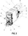
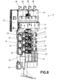
- the automated three-pole base (18) with at least one switching and protection device (1) of figures 1 to 8 corresponds to an embodiment of the invention, wherein said switching and protection device (1) comprises at least one circuit breaker (2) with two positions, connection and disconnection, such as a vacuum circuit breaker, equipped with a fixed contact (14) and a moving contact (13).
- the circuit breaker (2) can be operated locally and/or remotely, manually by means of buttons (45, 46) or motorized (for example, by means of a closing and opening coil), and has the capacity to break electrical currents due to overloads and short circuits, as well as open nominal or load currents.
- this vacuum circuit breaker (2) has fast, manual or automatic reclosing capacity, for the elimination of transient faults, and can be programmed depending on the time and type of fault, and carried out from a control unit (43) of the installation.
- the switching and protection device (1) comprises at least one first actuation means (3), such as a mechanical actuator, so that it activates the vacuum circuit breaker (2) to cause said switch (2) to pass from a closed status to an open status and vice versa.
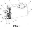
- the switching and protection device (1) also comprises at least one protection element (7), such as a fuse, against overloads and short-circuit currents and which is electrically connected in series with the vacuum circuit breaker (2). And as shown in said figures 1 to 4 , it also comprises at least one disconnector (5) with at least two switching positions, with the capacity of isolating (open disconnector) or connecting (closed disconnector) the low voltage switchboard (6) of the side of the low-voltage grid (16) that is downstream the switching and protection device (1), this disconnector (5) being electrically connected in series with the vacuum circuit breaker (2) and the protection element (7).
- the fixed contact (14) of the vacuum circuit breaker (2) is electrically connected to the disconnector (5) and the moving contact (13) of the vacuum circuit breaker (2) is electrically connected to the protection element (7) by means of a flexible conductor (24), as shown in figure 2 .
- the disconnector (5) comprises linearly sliding contacts (8, 9), as can be seen in figure 2 , the switching and protection device (1) comprising a second actuation means (10) that acts on the contacts (8 , 9) of the disconnector (5) to cause the passage of said disconnector (5) from a closed status to an open status and vice versa.
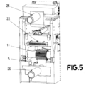
- the second actuation means (10) comprises a rack mechanism comprising at least one pinion (11) and a toothed bar (12), such that a rotation applied to the pinion (11) causes linear displacement of the toothed bar (12) and in turn the linear displacement of the moving contact (9) with respect to the fixed contact (8) of the disconnector (5).
- the actuation of the second actuation means (10) can be performed, for example, by means of an opening/closing lever (21), as can be seen in figure 3 , manually or in a motorized way.
- the disconnector (5) can also include a grounding means (17), as shown in Figure 4 , so that once the opening switching position of the disconnector (5) is obtained, the part of the low-voltage grid (16) that is downstream the switching and protection device (1), specifically the part of the low-voltage grid (16) that is downstream the disconnector (5), can be grounded against a possible voltage return from downstream towards the low voltage switchboard (6).
- the disconnector (5) also includes a check point (42) to be able to safely verify the presence of voltage and to be able to connect the part of the low-voltage grid (16) connected downstream to protective grounding, such as for maintenance work under safe conditions.
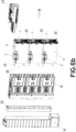
- Figures 4 and 6b show how the switching and protection device (1) comprises a casing (4) that can incorporate inside the two-position vacuum circuit breaker (2), the first actuation means (3), the disconnector (5) and the second actuation means (10), leaving the protection element (7) mounted on the outside of the casing (4) in a hole provided for this purpose, so that the protection element (7) can be accessible from outside the casing (4) and easily replaceable, keeping the low voltage switchboard in operation at all times.
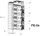
- the casing (4) comprises at least one handle (20) for insertion or extraction (manual or automated) of the switching and protection device (1) in a three-pole enclosure (15), said three-pole enclosure (15) being able to comprise up to three switching and protection devices (1), one for each phase (37), as can be seen in figures 1 , 6a , 6b and 8 .
- this three-pole enclosure (15) is mounted on a support (19).
- Figures 2 to 5 and Figures 6b and 8 show that the switching and protection device (1) comprises at least one input terminal (25) and one output terminal (26) at least partially incorporated in the casing (4), said terminals (25, 26) being electrically connected at one of their ends to a distribution busbar (27) of the low voltage switchboard (6) and with some bypass conductors (28) externally to the casing (4) , said terminals (25, 26) being electrically connected at the other end to the protection element (7) and the disconnector (5).
- the electrical connection between the input terminal (25) and the distribution busbar (27) and the electrical connection between the output terminal (26) and the bypass conductors (28) can be plug-in, screw-in or any other type.
- the switching and protection device (1) also comprises at least one interface (22), as shown in figure 5 , which allows connecting the control, operation and status sensors of each of the elements of the switching and protection device (1) with an electronic protection relay (23) for supervision, control and protection functions, as shown in figure 1 , with the protection relay (23) installed on the same automated three-pole base (18) where the switching and protection device (1) is installed, as shown in figures 6a , 6b and 8 .
- the interface (22) could also be directly connected to a control unit (43) of the installation or of the low voltage switchboard (6) instead of being connected to the electronic protection relay (23).
- Each protection relay (23) of each automated three-pole base (18) acquires different types of information for supervision purposes. All this information is transmitted by each protection relay (23) to the control unit (43), for example, as schematically shown in Figure 1 , via Ethernet, in order to store the information or send it to a remote client management and/or protection system. This information is of great help to monitor and control the low-voltage grid.
- the protection relay (23) can also know the status of the different elements, such as the vacuum circuit breaker (2) and the disconnector (5), and even remotely send/receive open/close/reclose commands for each one of the phases (37) or for each switching and protection device (1) individually of each automated three-pole base (18).
- the protection relay (23) includes the possibility of configuration and/or selection of standard or customized curves for protection against overloads and short circuits.
- the automated three-pole base (18) is made up of the support (19), a measurement means (39), the three-pole enclosure (15) with the switching and protection devices (1) and the protection relay (23).
- state-of-the-art three-pole fuse-holder bases (29) of a low-voltage switchboard (6) installed in the field and in operation can be replaced entirety or partially by automated three-pole bases (18) with switching and protection devices (1), with both protection systems being able to coexist on the same low-voltage switchboard (6) in operation, as shown in figure 8 .
- the switching and protection device (1) comprises mechanical and electrical interlocks to guarantee the protection of operators when carrying out operations prior to maintenance, repair or substitution of elements in the low voltage switchboard or in order to avoid unwanted operations.
- the mechanical and electrical interlocks that the switching and protection device (1) includes are:
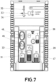
- the switching and protection device (1) comprises several signals, as shown in figure 7 , which allow viewing the status of the switching and protection device (1) itself, as well as the elements that it comprises, comprising the following indicator means:
- the automated three-pole base (18) with at least one switching and protection device (1) is applicable to low voltage switchboards (6).
- Figure 8 shows a low voltage switchboard (6) comprising at least one automated three-pole base (18) with at least one switching and protection device (1), wherein the low voltage switchboard (6) further comprises at least one set of connection bars (38), a distribution busbar (27), at least one measurement means (39), at least one auxiliary connection (40) and at least one auxiliary circuit output (41), as well as at least one support (19) on which the measurement means (39) is installed, a three-pole enclosure (15) equipped with at least one switching and protection device (1) and the electronic protection relay (23).
- the automated three-pole base (18) includes the support (19), the measuring means (39), the three-pole enclosure (15) with switching and protection devices (1) and the electronic protection relay (23).
- the support (19) comprises anchors for the mechanical fixing of the three-pole enclosure (15) equipped with at least one switching and protection device (1).
- the three-pole enclosure (15) includes a mechanical protection that prevents contact with live parts under voltage, such as the distribution busbar (27) or the bypass conductors (28) once the switching and protection device (1) has been removed from said three-pole enclosure (15), thus providing protection to people against access to dangerous parts and protection of the material against the harmful effects of mechanical impacts.
Landscapes
- Engineering & Computer Science (AREA)
- Power Engineering (AREA)
- Gas-Insulated Switchgears (AREA)
- Driving Mechanisms And Operating Circuits Of Arc-Extinguishing High-Tension Switches (AREA)
Claims (17)
- Automatisierte dreipolige Basis (18) mit Schalt- und Schutzvorrichtung (1) für ein Niederspannungsschaltfeld (6), wobei die Vorrichtung (1) Folgendes umfasst:• einen Schutzschalter (2) mit mindestens zwei Schaltstellungen, der Ströme aufgrund von Überlastungen und Kurzschlüssen sowie Nenn- oder Lastströme unterbrechen kann;• ein Schutzelement (7) gegen Überlastungen und Kurzschlussströme;• ein erstes Betätigungsmittel (3) des Schutzschalters (2); und• ein Gehäuse (4), in das der Schutzschalter (2) und das erste Betätigungsmittel (3) integriert sinddadurch gekennzeichnet, dass die Schalt- und Schutzvorrichtung (1) ferner einen Trennschalter (5) mit mindestens zwei Schaltstellungen umfasst, mit der Fähigkeit, das Niederspannungsschaltfeld (6) von dem Teil des Niederspannungsnetzes (16) zu trennen oder mit diesem zu verbinden, der stromabwärts der Schalt- und Schutzvorrichtung (1) liegt, wobei der Trennschalter (5) elektrisch in Reihe mit dem Schutzschalter (2) und dem Schutzelement (7) geschaltet ist, wobei der Trennschalter (5) zusammen mit dem Schutzschalter (2) und dem ersten Betätigungsmittel (3) in das Gehäuse (4) integriert ist.
- Automatisierte dreipolige Basis (18) gemäß Anspruch 1, dadurch gekennzeichnet, dass der Trennschalter (5) linear verschiebbare Kontakte (8, 9) umfasst.
- Automatisierte dreipolige Basis (18) gemäß Anspruch 1 oder 2, dadurch gekennzeichnet, dass die Schalt- und Schutzvorrichtung (1) ein zweites Betätigungsmittel (10) des Trennschalters (5) umfasst, wobei das zweite Betätigungsmittel (10) zusammen mit dem Schutzschalter (2), dem ersten Betätigungsmittel (3) und dem Trennschalter (5) in das Gehäuse (4) integriert ist.
- Automatisierte dreipolige Basis (18) gemäß Anspruch 3, dadurch gekennzeichnet, dass das zweite Betätigungsmittel (10) einen Zahnstangenmechanismus umfasst, der mit mindestens einem Ritzel (11) und einer Zahnstange (12) versehen ist, so dass eine auf das Ritzel (11) ausgeübte Drehung die lineare Verschiebung der Zahnstange (12) und wiederum die lineare Verschiebung des beweglichen Kontakts (9) des Trennschalters (5) bewirkt.
- Automatisierte dreipolige Basis (18) gemäß Anspruch 3 oder 4, dadurch gekennzeichnet, dass das zweite Betätigungsmittel (10) einen Hebel (21) zum Öffnen/Schließen des Trennschalters (5) umfasst.
- Automatisierte dreipolige Basis (18) gemäß einem der vorstehenden Ansprüche, dadurch gekennzeichnet, dass der Trennschalter (5) ein Erdungsmittel (17) umfasst.
- Automatisierte dreipolige Basis (18) gemäß Anspruch 1, dadurch gekennzeichnet, dass der Schutzschalter (2) ein Vakuum-Schutzschalter ist, der eine schnelle automatische oder manuelle Wiedereinschaltung ermöglicht und einen beweglichen Kontakt (13) und einen festen Kontakt (14) umfasst, wobei• der feste Kontakt (14) des Vakuum-Schutzschalters (2) elektrisch mit dem Trennschalter (5) verbunden ist;• der bewegliche Kontakt (13) des Vakuum-Schutzschalters (2) elektrisch mit dem Schutzelement (7) über einen flexiblen Leiter (24) verbunden ist und• der bewegliche Kontakt (13) des Vakuum-Schutzschalters (2) mechanisch mit dem ersten Betätigungsmittel (3) verbunden ist.
- Automatisierte dreipolige Basis (18) gemäß Anspruch 1, dadurch gekennzeichnet, dass die Schalt- und Schutzvorrichtung (1) zumindest teilweise in das Gehäuse (4) integriert, zumindest eine Eingangsklemme (25) mit einem Ende zum Anschluss an eine Verteilerschiene (27) und dem anderen Ende zum Anschluss an das Schutzelement (7) und zumindest eine Ausgangsklemme (26) mit einem Ende zum Anschluss an einige Bypass-Leiter (28) und dem anderen Ende zum Anschluss an den Trennschalter (5) umfasst.
- Automatisierte dreipolige Basis (18) nach Anspruch 1, dadurch gekennzeichnet, dass das Gehäuse (4) mindestens einen Griff (20) zum Einsetzen der Vorrichtung (1) in eine dreipolige Einfassung (15) oder zum Herausnehmen der Vorrichtung (1) aus einer dreipoligen Einfassung (15) umfasst, und wobei die dreipolige Einfassung (15) für jede Phase (37) eine Schalt- und Schutzvorrichtung (1) umfasst.
- Automatische dreipolige Basis (18) gemäß Anspruch 6, dadurch gekennzeichnet, dass der Trennschalter (5) einen Prüfpunkt (42) für das Vorhandensein von Spannung umfasst.
- Automatisierte dreipolige Basis (18) gemäß einem der vorstehenden Ansprüche, dadurch gekennzeichnet, dass die Schalt- und Schutzvorrichtung (1) eine erste Verriegelung (30) umfasst, die das Herausziehen der Schalt- und Schutzvorrichtung (1) aus der dreipoligen Einfassung (15) nur dann zulässt, wenn sich der Schutzschalter (2) in der geöffneten Schaltstellung befindet, oder die das Öffnen des Trennschalters (5) nur dann zulässt, wenn sich der Schutzschalter (2) in der geöffneten Schaltstellung befindet.
- Automatisierte dreipolige Basis (18) gemäß einem der vorstehenden Ansprüche, dadurch gekennzeichnet, dass die Schalt- und Schutzvorrichtung (1) eine zweite Verriegelung (31) umfasst, um die manuelle Schaltung durch den Knopf (45, 46) des Schutzschalters (2) zu verriegeln.
- Automatisierte dreipolige Basis (18) gemäß einem der vorstehenden Ansprüche, dadurch gekennzeichnet, dass die Schalt- und Schutzvorrichtung (1) eine dritte Verriegelung (32) umfasst, die es ermöglicht, die Schalt- und Schutzvorrichtung (1) nur dann zu erden, wenn sich der Trennschalter (5) in seiner geöffneten Schaltstellung befindet.
- Automatisierte dreipolige Basis (18) gemäß einem der vorstehenden Ansprüche, dadurch gekennzeichnet, dass die Schalt- und Schutzvorrichtung (1) eine vierte Verriegelung (47) umfasst, um die manuelle Federbelastung des ersten Betätigungsmittels (3) für den Betrieb des Schutzschalters (2) zu verriegeln.
- Automatisierte dreipolige Basis (18) gemäß einem der vorstehenden Ansprüche, dadurch gekennzeichnet, dass die Schalt- und Schutzvorrichtung (1) eine Schnittstelle (22) umfasst, um Steuer-, Betriebs- und Statussensoren jedes der Elemente der Vorrichtung (1) mit einem Schutzrelais (23) für Überwachungs-, Steuerungs- und Schutzfunktionen zu verbinden.
- Automatisierte dreipolige Basis (18) gemäß einem der vorstehenden Ansprüche, dadurch gekennzeichnet, dass die Schalt- und Schutzvorrichtung (1) Folgendes umfasst:• ein erstes visuelles Anzeigemittel (33) für die offene oder geschlossene Schaltstellung des Schutzschalters (2);• ein zweites visuelles Anzeigemittel (34) für die offene oder geschlossene Schaltstellung des Trennschalters (5);• ein drittes visuelles Anzeigemittel (35) für den Status des Schutzelements (7); und• ein viertes visuelles Anzeigemittel (36) für den Status des ersten Betätigungsmittels (3).
- Niederspannungsschaltfeld mit mindestens einer automatisierten dreipoligen Basis (18) gemäß einem der vorhergehenden Ansprüche, der außerdem mindestens einen Satz von Verbindungsschienen (38), eine Verteilerschiene (27), mindestens ein Messmittel (39), mindestens einen Hilfsanschluss (40), mindestens einen Hilfsstromkreisausgang (41) und mindestens eine Trennbasis (44) umfasst, dadurch gekennzeichnet, dass sie außerdem mindestens einen Träger (19) umfasst, auf dem das Messmittel (39), eine dreipolige Einfassung (15), die mit mindestens einer Schalt- und Schutzvorrichtung (1) ausgestattet ist, und das Schutzrelais (23) installiert sind, so dass die durch den Träger (19), den Messmitteln (39), der dreipoligen Einfassung (15) mit Schalt- und Schutzvorrichtungen (1) und den Schutzrelais (23) gebildete Anordnung eine automatische dreipolige Basis (18) darstellt.
Applications Claiming Priority (2)
| Application Number | Priority Date | Filing Date | Title |
|---|---|---|---|
| ES202131819U ES1280434Y (es) | 2021-09-14 | 2021-09-14 | Base tripolar automatizada con dispositivo de maniobra y protección para cuadro de baja tensión y cuadro de baja tensión que incorpora dicha base tripolar automatizada |
| PCT/ES2022/070580 WO2023041828A1 (es) | 2021-09-14 | 2022-09-14 | Base tripolar automatizada con dispositivo de maniobra y protección para cuadro de baja tensión y cuadro de baja tensión que incorpora dicha base tripolar automatizada |
Publications (3)
| Publication Number | Publication Date |
|---|---|
| EP4404229A1 EP4404229A1 (de) | 2024-07-24 |
| EP4404229C0 EP4404229C0 (de) | 2025-03-26 |
| EP4404229B1 true EP4404229B1 (de) | 2025-03-26 |
Family
ID=78203840
Family Applications (1)
| Application Number | Title | Priority Date | Filing Date |
|---|---|---|---|
| EP22800721.7A Active EP4404229B1 (de) | 2021-09-14 | 2022-09-14 | Automatisierte dreipolige basis mit schalt- und schutzvorrichtung für niederspannungsschaltfeld und niederspannungsschaltfeld mit der automatisierten dreipoligen basis |
Country Status (4)
| Country | Link |
|---|---|
| EP (1) | EP4404229B1 (de) |
| AR (1) | AR127672A1 (de) |
| ES (2) | ES1280434Y (de) |
| WO (1) | WO2023041828A1 (de) |
Citations (2)
| Publication number | Priority date | Publication date | Assignee | Title |
|---|---|---|---|---|
| WO2005020259A1 (de) * | 2003-07-25 | 2005-03-03 | Siemens Aktiengesellschaft | Sicherungsbehaftetes schaltschutzgerät |
| EP3195338B1 (de) * | 2014-09-15 | 2019-12-04 | Schneider Electric Limited | Stromverwaltungsvorrichtung |
Family Cites Families (5)
| Publication number | Priority date | Publication date | Assignee | Title |
|---|---|---|---|---|
| EP0670581A1 (de) * | 1994-03-04 | 1995-09-06 | Weber Ag | Als Schubeinsatz ausgebildeter Sicherungs-Lastschalter |
| ES2277729B1 (es) | 2005-04-04 | 2008-06-01 | Pronutec, S.A. | Base de seccionamiento tetrapolar vertical. |
| ES2763627B2 (es) | 2018-11-29 | 2021-07-01 | Ormazabal Corporate Tech A I E | Medio de maniobra y protección para cuadro de baja tensión y cuadro de baja tensión que incorpora dicho medio de maniobra y protección |
| EP3706264A1 (de) * | 2019-03-08 | 2020-09-09 | Gorlan Team, S.L.U. | Automatischer schalter |
| ES1243729Y1 (es) | 2020-02-19 | 2021-04-28 | Quijada Pablo Paunero | Dispositivo de seguridad y base tripolar |
-
2021
- 2021-09-14 ES ES202131819U patent/ES1280434Y/es active Active
-
2022
- 2022-09-14 EP EP22800721.7A patent/EP4404229B1/de active Active
- 2022-09-14 AR ARP220102488A patent/AR127672A1/es active IP Right Grant
- 2022-09-14 WO PCT/ES2022/070580 patent/WO2023041828A1/es not_active Ceased
- 2022-09-14 ES ES22800721T patent/ES3026792T3/es active Active
Patent Citations (2)
| Publication number | Priority date | Publication date | Assignee | Title |
|---|---|---|---|---|
| WO2005020259A1 (de) * | 2003-07-25 | 2005-03-03 | Siemens Aktiengesellschaft | Sicherungsbehaftetes schaltschutzgerät |
| EP3195338B1 (de) * | 2014-09-15 | 2019-12-04 | Schneider Electric Limited | Stromverwaltungsvorrichtung |
Also Published As
| Publication number | Publication date |
|---|---|
| EP4404229A1 (de) | 2024-07-24 |
| ES3026792T3 (en) | 2025-06-12 |
| ES1280434U (es) | 2021-10-29 |
| ES1280434Y (es) | 2023-09-21 |
| EP4404229C0 (de) | 2025-03-26 |
| WO2023041828A1 (es) | 2023-03-23 |
| AR127672A1 (es) | 2024-02-21 |
Similar Documents
| Publication | Publication Date | Title |
|---|---|---|
| US8493012B2 (en) | Protection relay, electrical switching apparatus, and system for determining and outputting fault current available at a load and incident energy or personal protective equipment level operatively associated therewith | |
| EP3889984B1 (de) | Schalt- und schutzmittel für niederspannungsverteiler und niederspannungsverteiler mit einem derartigen schalt- und schutzmittel | |
| US2805294A (en) | Mounting block for circuit breaker | |
| EP2600363B1 (de) | Verbindungsvorrichtung für umspannstationsmodule | |
| EP3195338B1 (de) | Stromverwaltungsvorrichtung | |
| KR100990736B1 (ko) | 보호 배전반의 상태를 감시하고 제어하는 보호 시스템 | |
| US20220181855A1 (en) | Busbar adapter with automatic switch | |
| EP2289138B1 (de) | Transformations-unterwerk | |
| EP4404229B1 (de) | Automatisierte dreipolige basis mit schalt- und schutzvorrichtung für niederspannungsschaltfeld und niederspannungsschaltfeld mit der automatisierten dreipoligen basis | |
| EP1148608B1 (de) | Verbesserungen in Ringleitungseinheiten | |
| US3009036A (en) | Circuit interrupter | |
| GB2466941A (en) | Consumer unit for housing residual current devices and miniature circuit breakers | |
| CN218919597U (zh) | 一种用于保护所用变压器的隔离负荷开关柜 | |
| Kimblin et al. | Low-voltage power circuit breakers and molded case circuit breakers-a comparison of test requirements | |
| Arana et al. | FIRST STEPS TOWARDS LV NETWORK AUTOMATION SOLUTIONS | |
| US20250391619A1 (en) | Circuit breaker and method | |
| Blower et al. | Trends in distribution transformer protection | |
| Krishna et al. | The Advantages of Smart Protective Relaying: Reviewing the Benefits | |
| Blower | New technology for secondary distribution systems | |
| HK1234201A1 (en) | Current management device | |
| HK1234201B (en) | Current management device | |
| Harris et al. | Ring main distribution switchgear-latest trends in use, control and operation | |
| Circuit-breaker | Chapter H LV switchgear: functions & selection | |
| Cardoso | Development of the power system protection: low voltage switchgear MNS | |
| Switchgear | An American National Standard IEEE Standard Definitions for |
Legal Events
| Date | Code | Title | Description |
|---|---|---|---|
| STAA | Information on the status of an ep patent application or granted ep patent |
Free format text: STATUS: UNKNOWN |
|
| STAA | Information on the status of an ep patent application or granted ep patent |
Free format text: STATUS: THE INTERNATIONAL PUBLICATION HAS BEEN MADE |
|
| PUAI | Public reference made under article 153(3) epc to a published international application that has entered the european phase |
Free format text: ORIGINAL CODE: 0009012 |
|
| STAA | Information on the status of an ep patent application or granted ep patent |
Free format text: STATUS: REQUEST FOR EXAMINATION WAS MADE |
|
| 17P | Request for examination filed |
Effective date: 20240319 |
|
| AK | Designated contracting states |
Kind code of ref document: A1 Designated state(s): AL AT BE BG CH CY CZ DE DK EE ES FI FR GB GR HR HU IE IS IT LI LT LU LV MC MK MT NL NO PL PT RO RS SE SI SK SM TR |
|
| GRAP | Despatch of communication of intention to grant a patent |
Free format text: ORIGINAL CODE: EPIDOSNIGR1 |
|
| STAA | Information on the status of an ep patent application or granted ep patent |
Free format text: STATUS: GRANT OF PATENT IS INTENDED |
|
| DAV | Request for validation of the european patent (deleted) | ||
| DAX | Request for extension of the european patent (deleted) | ||
| INTG | Intention to grant announced |
Effective date: 20241017 |
|
| GRAS | Grant fee paid |
Free format text: ORIGINAL CODE: EPIDOSNIGR3 |
|
| GRAA | (expected) grant |
Free format text: ORIGINAL CODE: 0009210 |
|
| STAA | Information on the status of an ep patent application or granted ep patent |
Free format text: STATUS: THE PATENT HAS BEEN GRANTED |
|
| AK | Designated contracting states |
Kind code of ref document: B1 Designated state(s): AL AT BE BG CH CY CZ DE DK EE ES FI FR GB GR HR HU IE IS IT LI LT LU LV MC MK MT NL NO PL PT RO RS SE SI SK SM TR |
|
| REG | Reference to a national code |
Ref country code: GB Ref legal event code: FG4D |
|
| REG | Reference to a national code |
Ref country code: CH Ref legal event code: EP |
|
| REG | Reference to a national code |
Ref country code: DE Ref legal event code: R096 Ref document number: 602022012363 Country of ref document: DE |
|
| REG | Reference to a national code |
Ref country code: IE Ref legal event code: FG4D |
|
| U01 | Request for unitary effect filed |
Effective date: 20250408 |
|
| U07 | Unitary effect registered |
Designated state(s): AT BE BG DE DK EE FI FR IT LT LU LV MT NL PT RO SE SI Effective date: 20250415 |
|
| REG | Reference to a national code |
Ref country code: ES Ref legal event code: FG2A Ref document number: 3026792 Country of ref document: ES Kind code of ref document: T3 Effective date: 20250612 |
|
| PG25 | Lapsed in a contracting state [announced via postgrant information from national office to epo] |
Ref country code: RS Free format text: LAPSE BECAUSE OF FAILURE TO SUBMIT A TRANSLATION OF THE DESCRIPTION OR TO PAY THE FEE WITHIN THE PRESCRIBED TIME-LIMIT Effective date: 20250626 |
|
| PG25 | Lapsed in a contracting state [announced via postgrant information from national office to epo] |
Ref country code: NO Free format text: LAPSE BECAUSE OF FAILURE TO SUBMIT A TRANSLATION OF THE DESCRIPTION OR TO PAY THE FEE WITHIN THE PRESCRIBED TIME-LIMIT Effective date: 20250626 |
|
| PG25 | Lapsed in a contracting state [announced via postgrant information from national office to epo] |
Ref country code: HR Free format text: LAPSE BECAUSE OF FAILURE TO SUBMIT A TRANSLATION OF THE DESCRIPTION OR TO PAY THE FEE WITHIN THE PRESCRIBED TIME-LIMIT Effective date: 20250326 |
|
| PG25 | Lapsed in a contracting state [announced via postgrant information from national office to epo] |
Ref country code: GR Free format text: LAPSE BECAUSE OF FAILURE TO SUBMIT A TRANSLATION OF THE DESCRIPTION OR TO PAY THE FEE WITHIN THE PRESCRIBED TIME-LIMIT Effective date: 20250627 |
|
| U20 | Renewal fee for the european patent with unitary effect paid |
Year of fee payment: 4 Effective date: 20250820 |
|
| REG | Reference to a national code |
Ref country code: CH Ref legal event code: U11 Free format text: ST27 STATUS EVENT CODE: U-0-0-U10-U11 (AS PROVIDED BY THE NATIONAL OFFICE) Effective date: 20251001 |
|
| PG25 | Lapsed in a contracting state [announced via postgrant information from national office to epo] |
Ref country code: SM Free format text: LAPSE BECAUSE OF FAILURE TO SUBMIT A TRANSLATION OF THE DESCRIPTION OR TO PAY THE FEE WITHIN THE PRESCRIBED TIME-LIMIT Effective date: 20250326 |
|
| PG25 | Lapsed in a contracting state [announced via postgrant information from national office to epo] |
Ref country code: PL Free format text: LAPSE BECAUSE OF FAILURE TO SUBMIT A TRANSLATION OF THE DESCRIPTION OR TO PAY THE FEE WITHIN THE PRESCRIBED TIME-LIMIT Effective date: 20250326 |
|
| PG25 | Lapsed in a contracting state [announced via postgrant information from national office to epo] |
Ref country code: SK Free format text: LAPSE BECAUSE OF FAILURE TO SUBMIT A TRANSLATION OF THE DESCRIPTION OR TO PAY THE FEE WITHIN THE PRESCRIBED TIME-LIMIT Effective date: 20250326 |
|
| PG25 | Lapsed in a contracting state [announced via postgrant information from national office to epo] |
Ref country code: IS Free format text: LAPSE BECAUSE OF FAILURE TO SUBMIT A TRANSLATION OF THE DESCRIPTION OR TO PAY THE FEE WITHIN THE PRESCRIBED TIME-LIMIT Effective date: 20250726 |
|
| U1N | Appointed representative for the unitary patent procedure changed after the registration of the unitary effect |
Representative=s name: HERRERO & ASOCIADOS, S.L.; ES |
|
| PGFP | Annual fee paid to national office [announced via postgrant information from national office to epo] |
Ref country code: CH Payment date: 20251001 Year of fee payment: 4 |
|
| PG25 | Lapsed in a contracting state [announced via postgrant information from national office to epo] |
Ref country code: CZ Free format text: LAPSE BECAUSE OF FAILURE TO SUBMIT A TRANSLATION OF THE DESCRIPTION OR TO PAY THE FEE WITHIN THE PRESCRIBED TIME-LIMIT Effective date: 20250326 |
|
| PGFP | Annual fee paid to national office [announced via postgrant information from national office to epo] |
Ref country code: ES Payment date: 20251003 Year of fee payment: 4 |
|
| PLBE | No opposition filed within time limit |
Free format text: ORIGINAL CODE: 0009261 |
|
| STAA | Information on the status of an ep patent application or granted ep patent |
Free format text: STATUS: NO OPPOSITION FILED WITHIN TIME LIMIT |
|
| REG | Reference to a national code |
Ref country code: CH Ref legal event code: L10 Free format text: ST27 STATUS EVENT CODE: U-0-0-L10-L00 (AS PROVIDED BY THE NATIONAL OFFICE) Effective date: 20260211 |
|
| 26N | No opposition filed |
Effective date: 20260105 |