EP3889372B1 - Set comprising a supporting structure, a fastening device and first and second panels - Google Patents
Set comprising a supporting structure, a fastening device and first and second panels Download PDFInfo
- Publication number
- EP3889372B1 EP3889372B1 EP21170441.6A EP21170441A EP3889372B1 EP 3889372 B1 EP3889372 B1 EP 3889372B1 EP 21170441 A EP21170441 A EP 21170441A EP 3889372 B1 EP3889372 B1 EP 3889372B1
- Authority
- EP
- European Patent Office
- Prior art keywords
- groove
- leg
- panel
- edge
- fastening device
- Prior art date
- Legal status (The legal status is an assumption and is not a legal conclusion. Google has not performed a legal analysis and makes no representation as to the accuracy of the status listed.)
- Active
Links
- 238000003780 insertion Methods 0.000 claims description 21
- 230000037431 insertion Effects 0.000 claims description 21
- 239000004743 Polypropylene Substances 0.000 claims description 4
- 239000002861 polymer material Substances 0.000 claims description 4
- 239000004952 Polyamide Substances 0.000 claims description 3
- 229920002647 polyamide Polymers 0.000 claims description 3
- 238000007373 indentation Methods 0.000 claims description 2
- -1 polypropylene Polymers 0.000 claims description 2
- 229920001155 polypropylene Polymers 0.000 claims description 2
- 239000002023 wood Substances 0.000 description 4
- 239000003365 glass fiber Substances 0.000 description 2
- 238000002347 injection Methods 0.000 description 2
- 239000007924 injection Substances 0.000 description 2
- 239000000463 material Substances 0.000 description 2
- 238000000034 method Methods 0.000 description 2
- 240000007594 Oryza sativa Species 0.000 description 1
- 235000007164 Oryza sativa Nutrition 0.000 description 1
- 239000004411 aluminium Substances 0.000 description 1
- 229910052782 aluminium Inorganic materials 0.000 description 1
- XAGFODPZIPBFFR-UHFFFAOYSA-N aluminium Chemical compound [Al] XAGFODPZIPBFFR-UHFFFAOYSA-N 0.000 description 1
- 238000012512 characterization method Methods 0.000 description 1
- 230000000694 effects Effects 0.000 description 1
- 239000000945 filler Substances 0.000 description 1
- 239000011888 foil Substances 0.000 description 1
- 239000010903 husk Substances 0.000 description 1
- 229910052751 metal Inorganic materials 0.000 description 1
- 239000002184 metal Substances 0.000 description 1
- 239000002245 particle Substances 0.000 description 1
- 239000011120 plywood Substances 0.000 description 1
- 229920000642 polymer Polymers 0.000 description 1
- 239000004800 polyvinyl chloride Substances 0.000 description 1
- 239000000843 powder Substances 0.000 description 1
- 235000009566 rice Nutrition 0.000 description 1
- 239000007787 solid Substances 0.000 description 1
- 239000012815 thermoplastic material Substances 0.000 description 1
Images


Classifications
-
- E—FIXED CONSTRUCTIONS
- E04—BUILDING
- E04F—FINISHING WORK ON BUILDINGS, e.g. STAIRS, FLOORS
- E04F13/00—Coverings or linings, e.g. for walls or ceilings
- E04F13/07—Coverings or linings, e.g. for walls or ceilings composed of covering or lining elements; Sub-structures therefor; Fastening means therefor
- E04F13/08—Coverings or linings, e.g. for walls or ceilings composed of covering or lining elements; Sub-structures therefor; Fastening means therefor composed of a plurality of similar covering or lining elements
- E04F13/0801—Separate fastening elements
- E04F13/0803—Separate fastening elements with load-supporting elongated furring elements between wall and covering elements
- E04F13/081—Separate fastening elements with load-supporting elongated furring elements between wall and covering elements with additional fastening elements between furring elements and covering elements
- E04F13/0821—Separate fastening elements with load-supporting elongated furring elements between wall and covering elements with additional fastening elements between furring elements and covering elements the additional fastening elements located in-between two adjacent covering elements
- E04F13/0826—Separate fastening elements with load-supporting elongated furring elements between wall and covering elements with additional fastening elements between furring elements and covering elements the additional fastening elements located in-between two adjacent covering elements engaging side grooves running along the whole length of the covering elements
-
- E—FIXED CONSTRUCTIONS
- E04—BUILDING
- E04B—GENERAL BUILDING CONSTRUCTIONS; WALLS, e.g. PARTITIONS; ROOFS; FLOORS; CEILINGS; INSULATION OR OTHER PROTECTION OF BUILDINGS
- E04B9/00—Ceilings; Construction of ceilings, e.g. false ceilings; Ceiling construction with regard to insulation
- E04B9/04—Ceilings; Construction of ceilings, e.g. false ceilings; Ceiling construction with regard to insulation comprising slabs, panels, sheets or the like
- E04B9/0435—Ceilings; Construction of ceilings, e.g. false ceilings; Ceiling construction with regard to insulation comprising slabs, panels, sheets or the like having connection means at the edges
-
- E—FIXED CONSTRUCTIONS
- E04—BUILDING
- E04B—GENERAL BUILDING CONSTRUCTIONS; WALLS, e.g. PARTITIONS; ROOFS; FLOORS; CEILINGS; INSULATION OR OTHER PROTECTION OF BUILDINGS
- E04B9/00—Ceilings; Construction of ceilings, e.g. false ceilings; Ceiling construction with regard to insulation
- E04B9/04—Ceilings; Construction of ceilings, e.g. false ceilings; Ceiling construction with regard to insulation comprising slabs, panels, sheets or the like
- E04B9/0464—Ceilings; Construction of ceilings, e.g. false ceilings; Ceiling construction with regard to insulation comprising slabs, panels, sheets or the like having irregularities on the faces, e.g. holes, grooves
-
- E—FIXED CONSTRUCTIONS
- E04—BUILDING
- E04B—GENERAL BUILDING CONSTRUCTIONS; WALLS, e.g. PARTITIONS; ROOFS; FLOORS; CEILINGS; INSULATION OR OTHER PROTECTION OF BUILDINGS
- E04B9/00—Ceilings; Construction of ceilings, e.g. false ceilings; Ceiling construction with regard to insulation
- E04B9/22—Connection of slabs, panels, sheets or the like to the supporting construction
- E04B9/24—Connection of slabs, panels, sheets or the like to the supporting construction with the slabs, panels, sheets or the like positioned on the upperside of, or held against the underside of the horizontal flanges of the supporting construction or accessory means connected thereto
- E04B9/245—Connection of slabs, panels, sheets or the like to the supporting construction with the slabs, panels, sheets or the like positioned on the upperside of, or held against the underside of the horizontal flanges of the supporting construction or accessory means connected thereto by means of screws, bolts or clamping strips held against the underside of the supporting construction
-
- E—FIXED CONSTRUCTIONS
- E04—BUILDING
- E04B—GENERAL BUILDING CONSTRUCTIONS; WALLS, e.g. PARTITIONS; ROOFS; FLOORS; CEILINGS; INSULATION OR OTHER PROTECTION OF BUILDINGS
- E04B9/00—Ceilings; Construction of ceilings, e.g. false ceilings; Ceiling construction with regard to insulation
- E04B9/22—Connection of slabs, panels, sheets or the like to the supporting construction
- E04B9/24—Connection of slabs, panels, sheets or the like to the supporting construction with the slabs, panels, sheets or the like positioned on the upperside of, or held against the underside of the horizontal flanges of the supporting construction or accessory means connected thereto
- E04B9/26—Connection of slabs, panels, sheets or the like to the supporting construction with the slabs, panels, sheets or the like positioned on the upperside of, or held against the underside of the horizontal flanges of the supporting construction or accessory means connected thereto by means of snap action of elastically deformable elements held against the underside of the supporting construction
-
- E—FIXED CONSTRUCTIONS
- E04—BUILDING
- E04F—FINISHING WORK ON BUILDINGS, e.g. STAIRS, FLOORS
- E04F15/00—Flooring
- E04F15/02—Flooring or floor layers composed of a number of similar elements
- E04F15/02044—Separate elements for fastening to an underlayer
-
- E—FIXED CONSTRUCTIONS
- E04—BUILDING
- E04F—FINISHING WORK ON BUILDINGS, e.g. STAIRS, FLOORS
- E04F15/00—Flooring
- E04F15/02—Flooring or floor layers composed of a number of similar elements
- E04F15/02177—Floor elements for use at a specific location
- E04F15/02183—Floor elements for use at a specific location for outdoor use, e.g. in decks, patios, terraces, verandas or the like
-
- E—FIXED CONSTRUCTIONS
- E04—BUILDING
- E04B—GENERAL BUILDING CONSTRUCTIONS; WALLS, e.g. PARTITIONS; ROOFS; FLOORS; CEILINGS; INSULATION OR OTHER PROTECTION OF BUILDINGS
- E04B9/00—Ceilings; Construction of ceilings, e.g. false ceilings; Ceiling construction with regard to insulation
- E04B9/04—Ceilings; Construction of ceilings, e.g. false ceilings; Ceiling construction with regard to insulation comprising slabs, panels, sheets or the like
- E04B9/0457—Ceilings; Construction of ceilings, e.g. false ceilings; Ceiling construction with regard to insulation comprising slabs, panels, sheets or the like having closed internal cavities
-
- E—FIXED CONSTRUCTIONS
- E04—BUILDING
- E04B—GENERAL BUILDING CONSTRUCTIONS; WALLS, e.g. PARTITIONS; ROOFS; FLOORS; CEILINGS; INSULATION OR OTHER PROTECTION OF BUILDINGS
- E04B9/00—Ceilings; Construction of ceilings, e.g. false ceilings; Ceiling construction with regard to insulation
- E04B9/06—Ceilings; Construction of ceilings, e.g. false ceilings; Ceiling construction with regard to insulation characterised by constructional features of the supporting construction, e.g. cross section or material of framework members
- E04B9/064—Ceilings; Construction of ceilings, e.g. false ceilings; Ceiling construction with regard to insulation characterised by constructional features of the supporting construction, e.g. cross section or material of framework members comprising extruded supporting beams
-
- E—FIXED CONSTRUCTIONS
- E04—BUILDING
- E04F—FINISHING WORK ON BUILDINGS, e.g. STAIRS, FLOORS
- E04F15/00—Flooring
- E04F15/02—Flooring or floor layers composed of a number of similar elements
- E04F15/02044—Separate elements for fastening to an underlayer
- E04F2015/0205—Separate elements for fastening to an underlayer with load-supporting elongated furring elements between the flooring elements and the underlayer
- E04F2015/02066—Separate elements for fastening to an underlayer with load-supporting elongated furring elements between the flooring elements and the underlayer with additional fastening elements between furring elements and flooring elements
- E04F2015/02077—Separate elements for fastening to an underlayer with load-supporting elongated furring elements between the flooring elements and the underlayer with additional fastening elements between furring elements and flooring elements the additional fastening elements located in-between two adjacent flooring elements
- E04F2015/02094—Engaging side grooves running along the whole length of the flooring elements
Definitions
- the present invention relates to a fastening device for connecting a panel to a supporting structure, such as a joist.
- Fastening devices such as a clip secured to a joist by a screw or nail, for connecting a panel to the joist are known from e.g. CA 2 792 923 .
- a clip device which is secured to a joist by bendable legs that are snapped around the joist, see e.g. DE202009007507U1 .
- Further sets comprising panels and fastening devices for securing them to a supporting structure are known from US 2009/217495 A1 or EP 2 096 232 A1 .
- a drawback with the known fastening devices is that it is time consuming to assemble the panel to the supporting structure.
- a further object is to provide a fastening device of a small size which may be easy to handle, transport and/or store.
- the invention comprises a set comprising a supporting structure, such as a joist, a first panel, a second panel and a fastening device for securing the first panel and the second panel to the supporting structure.
- the fastening device comprises a top portion, having a top surface, a bottom surface, a first edge portion and a second edge portion.
- a first leg and a second leg protrude downwardly from the bottom surface.
- the first panel comprises a first edge groove and the second panel comprises an opposite second edge groove.
- the first edge portion is configured to be inserted into the first edge groove and the second edge portion is configured to be inserted into the second edge groove.
- the first leg and the second leg are flexible and bendable towards each other.
- the first leg comprises a first locking element and the second leg comprises a second locking element.
- An upper surface of the supporting structure comprises an insertion groove comprising a first undercut groove and an opposite second undercut groove.
- the first locking element is configured to be snapped into the first undercut groove and the second locking element is configured to be snapped into the second undercut groove to a locked position.
- the first panel and the second panel are preferably essentially identical.
- the first edge groove and the second edge groove may be at a first long edge and a second long edge, respectively, of the first panel and the second panel.
- Two or more of said fastening device may be arranged along the first edge groove and the second edge groove.
- the fastening element is preferably configured to be inserted into the insertion groove by inserting the first edge portion into the first edge groove of the first panel and angling down the first panel against the upper surface of the supporting structure and pushing the panel vertically downwards such that the first and second legs are bent towards each other.
- the first locking element and the second locking element are configured to snap into the first undercut groove and the second undercut groove, respectively, when the locking device has reached a locked position.
- a lower surface of the first locking element and/or the second locking element may comprise a bevelled edge configured to cooperate with a groove edge of the insertion groove during an insertion of the first second leg and the second leg into the insertion groove.
- the top surface comprises a top groove, preferably with a curved surface, for receiving an outer edge of the second panel when the second panel is in angled position.
- the top groove may facilitate insertion of a second of said locking device in a first edge groove of the second panel by angling up the second panel before inserting the second of said locking device in a first edge groove of the second panel.
- the first locking element and the second locking element may each comprise an upper locking surface.
- the first and second undercut grooves may each comprise an upper surface.
- the locking surface of the first locking element may be configured to cooperate with the upper surface of the first undercut groove and the locking surface of the second locking element may be configured to cooperate with an upper surface of the second undercut groove.
- the locking surface of the first and second locking elements may each comprise a rounded or bevelled surface to enable an angled position of the fastening device while the first and second locking elements may be within the first and second undercut grooves, respectively.
- a lower surface of the first locking element and a lower surface of the second locking element may each comprise a bevelled edge or a rounded edge which is configured to interact with the supporting structure during an assembling of the set.
- the first leg may comprise a first outer surface and the second leg may comprise a second outer surface, wherein a distance between the first outer surface and the second outer surface may be essentially the same as a width of an opening of the insertion groove.
- the first leg may comprise a first outer surface and the second leg may comprise a second outer surface, wherein the first outer surface and/or the second outer surface may comprise a protruding element for a vertical positioning of the fastening device.
- the top portion comprises a friction connection, such as protruding parts, configured to cooperate with the first edge groove and/or the second edge groove and to restrain the fastening device from falling out during an assembling of the set.
- a friction connection such as protruding parts
- the fastening device may comprise a polymer material, such a polyamide e.g. PA6 or PA11/12, or polypropylene.
- the fastening device is preferably injection moulded.
- the material may be reinforced with e.g. glass fibre.
- a core of the first and second panels may be a wood-based core, such as solid wood or WPC.
- the core may comprise a polymer, such as a thermoplastic material, PP and PVC, and may comprise further components such as a filler, wood powder or rice husk.
- the core may also be of MDF, HDF, OSB, plywood, particle board or a metal such as aluminium.
- the WPC core may be provided with a decorative layer, such as a foil on one or more surfaces.
- the first and second panels may be decking, roof, wall or ceiling panels.
- FIGS 1A-B An embodiment of the invention is shown in FIGS 1A-B.
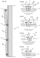
- FIG 1 shows a supporting structure 2, such as a joist, and a fastening device 1 for securing first and second panels 31, 32, see FIG 1B , to the supporting structure 2.
- FIG 1B shows a cross cut CS1b of the FIG 1A .
- the fastening device comprises a top portion 3, having a top surface 4, a bottom surface 5, a first edge portion 16 and a second edge portion 17, a first leg 6 and a second leg 7 protruding downwardly from the bottom surface.
- the first panel 31 comprises a first edge groove 33 and the second panel comprises an opposite second edge groove 34.
- the first edge portion 16 is configured to be inserted into the first edge groove 33 and the second edge portion 17 is configured to be inserted into the second edge groove 34.
- the first leg 6 and the second leg 7 are flexible and bendable towards each other.
- the first leg 6 comprises a first locking element 10 and the second leg 7 comprises a second locking element 11.
- An upper surface 18 of the supporting structure 2 comprises an insertion groove 12 comprising a first undercut groove 13 and an opposite second undercut groove 14.
- the first locking element 10 is configured to be snapped into the first undercut groove 13 and the second locking element 11 is configured to be snapped into the second undercut groove 14 to a locked position.
- the fastening element 1 is preferably configured to be inserted into the insertion groove 12 by inserting the first edge portion 16 into the first edge groove 33 of the first panel 31 and angling down the first panel 31 against the upper surface 18 of the supporting structure 2 and pushing the first panel 31 vertically downwards such that the first and second legs 6,7 are bent towards each other.
- the first and second locking elements 10,11 are configured to snap into the first and second undercut grooves 13,14, respectively, when the locking device has reached a locked position.
- FIG 2A shows an embodiment of the top portion 3 in a top view of an embodiment of the fastening device.
- a top surface 4 comprises a top groove 25, preferably with a curved surface, for receiving an outer edge of the second panel when the second panel is in angled position.
- the top surface 4 comprises a friction connection, such as protruding parts 24, configured to cooperate with the first edge groove and/or the second edge groove and to restrain the fastening device from falling out during an assembling of the fastening device and the supporting structure.
- FIG 2B shows a first side view and FIG 2C shows a second perpendicular side view of the embodiment shown in FIG 2A .
- a lower surface of the first locking element 10 and/or the second locking element 11 may each comprise a bevelled edge 21 configured to cooperate with a groove edge 22 of the insertion groove during an insertion of the first and second legs 6,7 into the insertion groove 12.
- the first locking element 10 and the second locking element 11 each comprise an upper locking surface 26.
- the locking surface 26 of the first locking element 10 is configured to cooperate with an upper surface of the first undercut groove 13 and the locking surface 26 of the second locking element 11 is configured to cooperate with an upper surface of the second undercut groove 14.
- the locking surface 26 of the first and second locking elements 10,11 may each comprise a rounded or bevelled surface to enable an angled position of the fastening device 1.
- a lower surface of the first locking element 10 and a lower surface of the second locking element 11 may each comprise a bevelled edge or rounded edge 28 which is configured to interact with the supporting structure during an assembling.
- the bevelled edge or the rounded edge 28 is configured such that the fastening device remains in the first edge groove during an assembling comprising an angling movement.
- the lower surface of the first locking element and the second locking element, respectively, may be configured to cooperate with a wall surface of the supporting structure for a vertical positioning of the fastening device 1.
- An embodiment of an assembling is shown in FIGS 3A-3E .
- the first leg 6 comprises a first outer surface 8 and the second leg 7 comprises a second outer surface 9.
- a distance between the first outer surface and the second outer surface is preferably essentially the same as a width of an opening of the insertion groove.
- the first outer surface and/or the second outer surface may comprise a protruding element 27 for a vertical positioning of the fastening device 1.
- a preferred embodiment of the fastening device comprises a polymer material, such a polyamide, e.g. PA6, PA11/12 or PP.
- the fastening device is preferably injection moulded.
- the material may be reinforced with e.g. glass fibre.
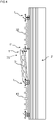
- FIGS 3A - 3E show an embodiment of an assembling of embodiments of said panels, fastening elements and supporting structure.
- FIG 3A shows an installed panel 30, the first panel 31 and the second panel 32, which are preferably essentially identical.
- a joint between the installed panel and the first panel and a joint between the first panel and the second panel each comprise at least one of said fastening device 1.
- the first groove and the second groove of the installed panel 30, the first panel 31 and the second panel 32 are preferably provided at long edges of the installed panel 30, the first panel 31 and the second panel 32, respectively.
- the second groove of the installed panel is connected to the supporting structure by one or more of said fastening device 1.
- the first edge portion 16 of one of said fastening device 1 is inserted into the first edge groove of the second panel 32.
- FIGS 3B-3E each show an enlargement of a joint during assembling between the panels shown in FIG 3A.
- FIG 3B shows that the first panel 31 is displaced in a horizontal direction 35 towards the installed panel 30 until the first edge portion of the fastening device 1 is inserted into the second edge groove of the first panel 31.
- FIG 3B shows that the first panel is angled upward 36 to an angled position to enable insertion of the first edge portion 16 of at least one of said fastening device 1 into the first edge groove of the first panel 31.
- FIG 3D shows that the first panel, with the first edge portion 16 of at least one of said fastening device 1 provided in the first edge groove, is angled downward 37.
- the first panel 31 is pushed vertically downwards until the fastening device has reached the locked position shown in FIG 3E .
- the second panel 32 is connected to the first panel 31 by displacing the second panel in a horizontal direction until the first edge portion of the fastening device 1 is inserted into the second edge groove of the second panel 31.
- FIG 4 and FIG 5 show an embodiment of replacing an assembled first panel and reassembling the panels. Replacing an assembled panel may be desired if the assembled panel is damaged or if access is required to a space under the assembled panel.
- the assembled first panel may be cut and removed and replaced by a new first panel 31.
- the fastening device 1 may be divided into two halves as indicated by the lines R in FIG 2A and FIG 6B .
- the fastening device may comprise one or more indentations that facilitate dividing of the fastening device.
- replacement fastening devices are provided, which are configured as a left half 1' of the fastening device and a right half 1".
- An enlargement of the left half is shown in FIG 6C .
- the first and second legs 6,7 may be downwardly narrowing in order to facilitate angling in of the new first panel.
- the first edge portion 16 of the left half 1' is inserted into the first edge grove of the new first panel 31 and the second edge portion 17 of the right half 1" is inserted into the second edge groove of the second panel 32 as shown in FIG 4 .
- the new first panel is thereafter angled down to the assembled position shown in FIG 5 .
- Oblique edges 72 of the downwardly narrowing first and second legs 6,7 may have the effect that a collision with the second panel 32 is avoided.
- FIG 6A shows an embodiment of said supporting structure 2 which may be fixed to a joist, e.g. a wood joist.
- the supporting structure may be fixed by e.g. a screw or a nail.
- the protruding elements 27 cooperate with a surface of the supporting structure 2 for vertical positioning of the fastening device 1.
- FIG 6B shows an embodiment of said fastening device.
- the first leg 6 and the second leg 7 (not shown) each comprise a dividing groove 15 in order to increase the flexibility of the first leg.
- the dividing groove may have parallel edges 75 as shown in the figure or non-parallel oblique edges such that the dividing groove is downwardly widening.
- FIG 7A-7C shows an embodiment of the fastening device 1 that may be divided into two halves as indicated by the lines R.
- FIG 7A shows a top view
- FIG 7B shows a first side view
- FIG 7C shows a second perpendicular side view of the embodiment.
- the top portion 3 of fastening device comprises a groove 71 that facilitates dividing of the fastening device into two halves as indicated by the lines R.
- the first leg 6 and the second leg 7 may each comprise a first securing element 76 and a second securing element 77.
- the first securing element 76 and the second securing 77 are configured for securing the fastening device 1 to the first panel and the second panel respectively during assembling.
- the first and second securing elements preferably protrude from a lower part of the first leg and the second leg.
- the first leg 6 and the second leg 7 each comprise a dividing groove 15 in order to increase the flexibility of the first leg.
- the dividing groove may have oblique edges 72 such that the dividing groove is downwardly widening.
- the first and second locking elements 10, 11 each preferably comprise a downwardly sloping locking surface 26.
- FIG 8A shows an embodiment of the replacing of an assembled first panel and reassembling the panels.
- the embodiment comprising securing a left half of the fastening device to the first panel 31 and a right half of the fastening device to the second panel 32.
- the left half is secured to the first panel by a first securing element 76 and the right half is secured to the second panel by a second securing element 77, and the first panel is angled downwards 73.
- FIG 8B shows an embodiment of the fastening device comprising a locking surface 26 sloping downwards. This may facilitate snapping in of the first and second locking elements into the first undercut groove and the second undercut groove, respectively, particularly if the vertical position of the locking surface is not completely correct in relation to the first undercut or the second undercut.
- FIG 8C shows, in a crosscut view, an embodiment of the fastening device comprising a top portion 3 comprising a groove 71 that facilitate dividing of the fastening device into a left half and a right half by turning 74 the right half from the left half.
- the replacing method shown in FIG 8A may comprise the left half and the right half according to this embodiment.
- a set comprises a supporting structure 2, such as a joist, a first panel 31, a second panel 32 and a fastening device 1 for securing the first and second panels 31, 32 to the supporting structure 2.
- the fastening device 1 comprises a top portion 3, having a top surface 4, a bottom surface 5, a first edge portion 16 and a second edge portion 17, a first leg 6 and a second leg 7 protruding downwardly from the bottom surface 5.
- the first panel 31 comprises a first edge groove 33
- the second panel 32 comprises an opposite second edge groove 34.
- the first edge portion 16 is configured to be inserted into the first edge groove 33 and the second edge portion 17 is configured to be inserted into the second edge groove 34.
- the first leg 6 and the second leg 7 are flexible and bendable towards each other.
- the first leg 6 comprises a first locking element 10
- the second leg 7 comprises a second locking element 11.
- An upper surface 18 of the supporting structure 2 comprises an insertion groove 12 comprising a first undercut groove 13 and an opposite second undercut groove 14.
- the first locking element 10 is configured to be snapped into the first undercut groove 13 and the second locking element 11 is configured to be snapped into the second undercut groove 14 to a locked position.
Description
- The present invention relates to a fastening device for connecting a panel to a supporting structure, such as a joist.
- Fastening devices, such as a clip secured to a joist by a screw or nail, for connecting a panel to the joist are known from e.g.
CA 2 792 923 . Also known is a clip device which is secured to a joist by bendable legs that are snapped around the joist, see e.g.DE202009007507U1 . Further sets comprising panels and fastening devices for securing them to a supporting structure are known fromUS 2009/217495 A1 orEP 2 096 232 A1 - A drawback with the known fastening devices is that it is time consuming to assemble the panel to the supporting structure.
- The above description of various known aspects is the applicant's characterization of such, and is not an admission that any of the above description is considered as prior art.
- It is an object of certain embodiments of the present invention to provide an improvement over the above described techniques and known art. Particularly to reduce the time for assembling and to provide a tool-less assembling. A further object is to provide a fastening device of a small size which may be easy to handle, transport and/or store.
- The invention is defined by the appended claims.
- At least some of these and other objects and advantages that will be apparent from the description have been achieved by the invention that comprises a set comprising a supporting structure, such as a joist, a first panel, a second panel and a fastening device for securing the first panel and the second panel to the supporting structure. The fastening device comprises a top portion, having a top surface, a bottom surface, a first edge portion and a second edge portion. A first leg and a second leg protrude downwardly from the bottom surface. The first panel comprises a first edge groove and the second panel comprises an opposite second edge groove. The first edge portion is configured to be inserted into the first edge groove and the second edge portion is configured to be inserted into the second edge groove. The first leg and the second leg are flexible and bendable towards each other. The first leg comprises a first locking element and the second leg comprises a second locking element. An upper surface of the supporting structure comprises an insertion groove comprising a first undercut groove and an opposite second undercut groove. The first locking element is configured to be snapped into the first undercut groove and the second locking element is configured to be snapped into the second undercut groove to a locked position.
- The first panel and the second panel are preferably essentially identical.
- The first edge groove and the second edge groove may be at a first long edge and a second long edge, respectively, of the first panel and the second panel. Two or more of said fastening device may be arranged along the first edge groove and the second edge groove.
- The fastening element is preferably configured to be inserted into the insertion groove by inserting the first edge portion into the first edge groove of the first panel and angling down the first panel against the upper surface of the supporting structure and pushing the panel vertically downwards such that the first and second legs are bent towards each other. The first locking element and the second locking element are configured to snap into the first undercut groove and the second undercut groove, respectively, when the locking device has reached a locked position.
- A lower surface of the first locking element and/or the second locking element may comprise a bevelled edge configured to cooperate with a groove edge of the insertion groove during an insertion of the first second leg and the second leg into the insertion groove.
- The top surface comprises a top groove, preferably with a curved surface, for receiving an outer edge of the second panel when the second panel is in angled position. The top groove may facilitate insertion of a second of said locking device in a first edge groove of the second panel by angling up the second panel before inserting the second of said locking device in a first edge groove of the second panel.
- The first locking element and the second locking element may each comprise an upper locking surface. The first and second undercut grooves may each comprise an upper surface. The locking surface of the first locking element may be configured to cooperate with the upper surface of the first undercut groove and the locking surface of the second locking element may be configured to cooperate with an upper surface of the second undercut groove.
- The locking surface of the first and second locking elements may each comprise a rounded or bevelled surface to enable an angled position of the fastening device while the first and second locking elements may be within the first and second undercut grooves, respectively.
- A lower surface of the first locking element and a lower surface of the second locking element may each comprise a bevelled edge or a rounded edge which is configured to interact with the supporting structure during an assembling of the set.
- The first leg may comprise a first outer surface and the second leg may comprise a second outer surface, wherein a distance between the first outer surface and the second outer surface may be essentially the same as a width of an opening of the insertion groove.
- The first leg may comprise a first outer surface and the second leg may comprise a second outer surface, wherein the first outer surface and/or the second outer surface may comprise a protruding element for a vertical positioning of the fastening device.
- The top portion comprises a friction connection, such as protruding parts, configured to cooperate with the first edge groove and/or the second edge groove and to restrain the fastening device from falling out during an assembling of the set.
- The fastening device may comprise a polymer material, such a polyamide e.g. PA6 or PA11/12, or polypropylene. The fastening device is preferably injection moulded. The material may be reinforced with e.g. glass fibre.
- A core of the first and second panels may be a wood-based core, such as solid wood or WPC. The core may comprise a polymer, such as a thermoplastic material, PP and PVC, and may comprise further components such as a filler, wood powder or rice husk. The core may also be of MDF, HDF, OSB, plywood, particle board or a metal such as aluminium. The WPC core may be provided with a decorative layer, such as a foil on one or more surfaces.
- The first and second panels may be decking, roof, wall or ceiling panels.
- The present invention will by way of example be described in more detail with reference to the appended schematic drawings, which show embodiments of the present invention.
-
FIGS. 1A-1B show an embodiment of the invention. -
FIGS. 2A-2C show an embodiment of the fastening device according to an embodiment of the invention. -
FIGS. 3A-3E show an embodiment of an assembling of an embodiment of the invention. -
FIG. 4 shows an embodiment of an assembling of an embodiment of the invention -
FIG. 5 shows an embodiment of the invention in an assembled position. -
FIG. 6A-6C show embodiments of the invention. -
FIGS. 7A-7C show an embodiment of the fastening device according to an embodiment of the invention. -
FIGS. 8A-8C show embodiments of the invention. - An embodiment of the invention is shown in
FIGS 1A-B. FIG 1 shows a supportingstructure 2, such as a joist, and afastening device 1 for securing first andsecond panels FIG 1B , to the supportingstructure 2.FIG 1B shows a cross cut CS1b of theFIG 1A . The fastening device comprises atop portion 3, having atop surface 4, abottom surface 5, afirst edge portion 16 and asecond edge portion 17, afirst leg 6 and asecond leg 7 protruding downwardly from the bottom surface. Thefirst panel 31 comprises afirst edge groove 33 and the second panel comprises an oppositesecond edge groove 34. Thefirst edge portion 16 is configured to be inserted into thefirst edge groove 33 and thesecond edge portion 17 is configured to be inserted into thesecond edge groove 34. Thefirst leg 6 and thesecond leg 7 are flexible and bendable towards each other. Thefirst leg 6 comprises afirst locking element 10 and thesecond leg 7 comprises asecond locking element 11. Anupper surface 18 of the supportingstructure 2 comprises aninsertion groove 12 comprising a first undercutgroove 13 and an opposite second undercutgroove 14. Thefirst locking element 10 is configured to be snapped into the first undercutgroove 13 and thesecond locking element 11 is configured to be snapped into the second undercutgroove 14 to a locked position. Thefastening element 1 is preferably configured to be inserted into theinsertion groove 12 by inserting thefirst edge portion 16 into thefirst edge groove 33 of thefirst panel 31 and angling down thefirst panel 31 against theupper surface 18 of the supportingstructure 2 and pushing thefirst panel 31 vertically downwards such that the first andsecond legs second locking elements undercut grooves -
FIG 2A shows an embodiment of thetop portion 3 in a top view of an embodiment of the fastening device. Atop surface 4 comprises atop groove 25, preferably with a curved surface, for receiving an outer edge of the second panel when the second panel is in angled position. Thetop surface 4 comprises a friction connection, such as protrudingparts 24, configured to cooperate with the first edge groove and/or the second edge groove and to restrain the fastening device from falling out during an assembling of the fastening device and the supporting structure.FIG 2B shows a first side view andFIG 2C shows a second perpendicular side view of the embodiment shown inFIG 2A . A lower surface of thefirst locking element 10 and/or thesecond locking element 11 may each comprise abevelled edge 21 configured to cooperate with agroove edge 22 of the insertion groove during an insertion of the first andsecond legs insertion groove 12. Thefirst locking element 10 and thesecond locking element 11 each comprise anupper locking surface 26. The lockingsurface 26 of thefirst locking element 10 is configured to cooperate with an upper surface of the first undercutgroove 13 and the lockingsurface 26 of thesecond locking element 11 is configured to cooperate with an upper surface of the second undercutgroove 14. - The locking
surface 26 of the first andsecond locking elements fastening device 1. - A lower surface of the
first locking element 10 and a lower surface of thesecond locking element 11 may each comprise a bevelled edge or roundededge 28 which is configured to interact with the supporting structure during an assembling. The bevelled edge or therounded edge 28 is configured such that the fastening device remains in the first edge groove during an assembling comprising an angling movement. The lower surface of the first locking element and the second locking element, respectively, may be configured to cooperate with a wall surface of the supporting structure for a vertical positioning of thefastening device 1. An embodiment of an assembling is shown inFIGS 3A-3E . - The
first leg 6 comprises a firstouter surface 8 and thesecond leg 7 comprises a second outer surface 9. A distance between the first outer surface and the second outer surface is preferably essentially the same as a width of an opening of the insertion groove. - The first outer surface and/or the second outer surface may comprise a protruding
element 27 for a vertical positioning of thefastening device 1. - A preferred embodiment of the fastening device comprises a polymer material, such a polyamide, e.g. PA6, PA11/12 or PP. The fastening device is preferably injection moulded. The material may be reinforced with e.g. glass fibre.
-
FIGS 3A - 3E show an embodiment of an assembling of embodiments of said panels, fastening elements and supporting structure.FIG 3A shows an installedpanel 30, thefirst panel 31 and thesecond panel 32, which are preferably essentially identical. A joint between the installed panel and the first panel and a joint between the first panel and the second panel each comprise at least one of saidfastening device 1. The first groove and the second groove of the installedpanel 30, thefirst panel 31 and thesecond panel 32, are preferably provided at long edges of the installedpanel 30, thefirst panel 31 and thesecond panel 32, respectively. The second groove of the installed panel is connected to the supporting structure by one or more of saidfastening device 1. Thefirst edge portion 16 of one of saidfastening device 1 is inserted into the first edge groove of thesecond panel 32.FIGS 3B-3E each show an enlargement of a joint during assembling between the panels shown inFIG 3A. FIG 3B shows that thefirst panel 31 is displaced in ahorizontal direction 35 towards the installedpanel 30 until the first edge portion of thefastening device 1 is inserted into the second edge groove of thefirst panel 31.FIG 3B shows that the first panel is angled upward 36 to an angled position to enable insertion of thefirst edge portion 16 of at least one of saidfastening device 1 into the first edge groove of thefirst panel 31.FIG 3D shows that the first panel, with thefirst edge portion 16 of at least one of saidfastening device 1 provided in the first edge groove, is angled downward 37. Thefirst panel 31 is pushed vertically downwards until the fastening device has reached the locked position shown inFIG 3E . Thesecond panel 32 is connected to thefirst panel 31 by displacing the second panel in a horizontal direction until the first edge portion of thefastening device 1 is inserted into the second edge groove of thesecond panel 31. -
FIG 4 andFIG 5 show an embodiment of replacing an assembled first panel and reassembling the panels. Replacing an assembled panel may be desired if the assembled panel is damaged or if access is required to a space under the assembled panel. The assembled first panel may be cut and removed and replaced by a newfirst panel 31. - The
fastening device 1 may be divided into two halves as indicated by the lines R inFIG 2A andFIG 6B . The fastening device may comprise one or more indentations that facilitate dividing of the fastening device. - Another alternative is that replacement fastening devices are provided, which are configured as a
left half 1' of the fastening device and aright half 1". An enlargement of the left half is shown inFIG 6C . The first andsecond legs first edge portion 16 of theleft half 1' is inserted into the first edge grove of the newfirst panel 31 and thesecond edge portion 17 of theright half 1" is inserted into the second edge groove of thesecond panel 32 as shown inFIG 4 . The new first panel is thereafter angled down to the assembled position shown inFIG 5 . Oblique edges 72 of the downwardly narrowing first andsecond legs second panel 32 is avoided. -
FIG 6A shows an embodiment of said supportingstructure 2 which may be fixed to a joist, e.g. a wood joist. The supporting structure may be fixed by e.g. a screw or a nail. There is no contact at the lower surface of thefirst locking element 10 and the lower surface of thesecond locking element 11. The protrudingelements 27 cooperate with a surface of the supportingstructure 2 for vertical positioning of thefastening device 1. -
FIG 6B shows an embodiment of said fastening device. Thefirst leg 6 and the second leg 7 (not shown) each comprise a dividinggroove 15 in order to increase the flexibility of the first leg. The dividing groove may haveparallel edges 75 as shown in the figure or non-parallel oblique edges such that the dividing groove is downwardly widening. -
FIG 7A-7C shows an embodiment of thefastening device 1 that may be divided into two halves as indicated by the lines R.FIG 7A shows a top view,FIG 7B shows a first side view andFIG 7C shows a second perpendicular side view of the embodiment. Thetop portion 3 of fastening device comprises agroove 71 that facilitates dividing of the fastening device into two halves as indicated by the lines R. - The
first leg 6 and thesecond leg 7 may each comprise a first securingelement 76 and asecond securing element 77. Thefirst securing element 76 and the second securing 77 are configured for securing thefastening device 1 to the first panel and the second panel respectively during assembling. The first and second securing elements preferably protrude from a lower part of the first leg and the second leg. - The
first leg 6 and thesecond leg 7 each comprise a dividinggroove 15 in order to increase the flexibility of the first leg. The dividing groove may haveoblique edges 72 such that the dividing groove is downwardly widening. The first andsecond locking elements surface 26. -
FIG 8A shows an embodiment of the replacing of an assembled first panel and reassembling the panels. The embodiment comprising securing a left half of the fastening device to thefirst panel 31 and a right half of the fastening device to thesecond panel 32. The left half is secured to the first panel by a first securingelement 76 and the right half is secured to the second panel by asecond securing element 77, and the first panel is angled downwards 73. -
FIG 8B shows an embodiment of the fastening device comprising a lockingsurface 26 sloping downwards. This may facilitate snapping in of the first and second locking elements into the first undercut groove and the second undercut groove, respectively, particularly if the vertical position of the locking surface is not completely correct in relation to the first undercut or the second undercut. -
FIG 8C shows, in a crosscut view, an embodiment of the fastening device comprising atop portion 3 comprising agroove 71 that facilitate dividing of the fastening device into a left half and a right half by turning 74 the right half from the left half. The replacing method shown inFIG 8A may comprise the left half and the right half according to this embodiment. - In an
embodiment 1, a set comprises a supportingstructure 2, such as a joist, afirst panel 31, asecond panel 32 and afastening device 1 for securing the first andsecond panels structure 2. Thefastening device 1 comprises atop portion 3, having atop surface 4, abottom surface 5, afirst edge portion 16 and asecond edge portion 17, afirst leg 6 and asecond leg 7 protruding downwardly from thebottom surface 5. Thefirst panel 31 comprises afirst edge groove 33, and thesecond panel 32 comprises an oppositesecond edge groove 34. Thefirst edge portion 16 is configured to be inserted into thefirst edge groove 33 and thesecond edge portion 17 is configured to be inserted into thesecond edge groove 34. Thefirst leg 6 and thesecond leg 7 are flexible and bendable towards each other. Thefirst leg 6 comprises afirst locking element 10, and thesecond leg 7 comprises asecond locking element 11. Anupper surface 18 of the supportingstructure 2 comprises aninsertion groove 12 comprising a first undercutgroove 13 and an opposite second undercutgroove 14. Thefirst locking element 10 is configured to be snapped into the first undercutgroove 13 and thesecond locking element 11 is configured to be snapped into the second undercutgroove 14 to a locked position.
Claims (15)
- A set comprising a supporting structure (2), a first panel (31), a second panel (32) and a fastening device (1) for securing the first and second panels (31, 32) to the supporting structure (2), wherein the fastening device comprises a top portion (3), having a top surface (4), a bottom surface (5), a first edge portion (16) and a second edge portion (17), a first leg (6) and a second leg (7) protruding downwardly from the bottom surface, wherein the first panel (31) comprises a first edge groove (33) and the second panel (32) comprises an opposite second edge groove (34), the first edge portion (16) being configured to be inserted into the first edge groove (33) and the second edge portion (17) being configured to be inserted into the second edge groove (34), whereinthe first leg (6) and the second leg (7) are flexible and bendable towards each other;the top portion comprises a friction connection configured to cooperate with the first edge groove (33) and/or the second edge groove (32) and to restrain the fastening device from falling out during an assembling of the set,the top surface (4) comprises a top groove (25) for receiving an outer edge of the second panel when the second panel is in angled position,characterised in thatthe first leg (6) comprises a first locking element (10) and the second leg (7) comprises a second locking element (11);an upper surface (18) of the supporting structure (2) comprises an insertion groove (12) comprising a first undercut groove (13) and an opposite second undercut groove (14);the first locking element (10) is configured to be snapped into the first undercut groove (13) and the second locking element (11) is configured to be snapped into the second undercut groove (14) to a locked position.
- The set as claimed in claim 1, wherein the supporting structure (2) includes a joist.
- The set as claimed in claim 1 or 2, wherein a lower surface of the first locking element (10) and/or the second locking element (11) comprises a bevelled edge (21) configured to cooperate with a groove edge (22) of the insertion groove during an insertion of the first leg and the second leg (6,7) into the insertion groove (12).
- The set as claimed in claim 1, wherein the top groove (25) of the top surface (4) has a curved surface.
- The set as claimed in any one of the preceding claims, wherein the first locking element (10) and the second locking element (11) each comprise an upper locking surface (26), wherein the locking surface (26) of the first locking element (10) is configured to cooperate with an upper surface of the first undercut groove (13) and the locking surface (26) of the second locking element (11) is configured to cooperate with an upper surface of the second undercut groove (14).
- The set as claimed in claim 5, wherein the locking surface (26) of the first and second locking elements (10,11) each comprise a rounded or bevelled surface to enable an angled position of the fastening device.
- The set as claimed in any one of the preceding claims, wherein a lower surface of the first locking element (10) and a lower surface of the second locking element (11) each comprise a bevelled edge or rounded edge (28) which is configured to interact with the supporting structure during an assembling.
- The set as claimed in any one of the preceding claims, wherein the first leg (10) comprises a first outer surface (8) and the second leg (11) comprises a second outer surface (9), and wherein a distance between the first outer surface and the second outer surface is essentially the same as a width of an opening of the insertion groove.
- The set as claimed in any one of the preceding claims, wherein the first leg (10) comprises a first outer surface (8) and the second leg (11) comprises a second outer surface (9), wherein the first outer surface and/or the second outer surface comprise(s) a protruding element (27) for a vertical positioning of the fastening device (1).
- The set as claimed in claim 1, wherein the friction connection includes protruding parts.
- The set as claimed in any preceding claim 1-10, wherein the first leg (6) and the second leg (7) each comprises a dividing groove (15) in order to increase the flexibility of the first leg and second leg respectively, preferably the dividing groove has oblique edges (72) such that the dividing groove is downwardly widening.
- The set as claimed in any preceding claim 1-11, wherein the fastening element is configured to be inserted into the insertion groove (12) by inserting the first edge portion (16) into the first edge groove (33) of the first panel and angling down the first panel against the upper surface of the supporting structure and pushing the panel vertically downwards such that the first and second legs are bent towards each other, wherein the first locking element (10) and the second locking element (11) are configured to snap into the first undercut groove and the second undercut groove, respectively, when the locking device has reached a locked position.
- The set as claimed in any preceding claim 1-12, wherein the fastening device (1) is configured to be divided into two halves, preferably the top portion (3) of fastening device comprises a groove (71) that facilitates dividing of the fastening device into two halves or the fastening device comprises one or more indentations that facilitate dividing of the fastening device.
- The set as claimed in any one of the preceding claims, wherein the fastening device (1) comprises a polymer material.
- The set as claimed in claim 14, wherein the polymer material includes polyamide or polypropylene.
Applications Claiming Priority (3)
| Application Number | Priority Date | Filing Date | Title |
|---|---|---|---|
| SE1551091 | 2015-08-24 | ||
| EP16839698.4A EP3341540B1 (en) | 2015-08-24 | 2016-08-22 | Method of assembling two identical panels to a supporting structure |
| PCT/SE2016/050777 WO2017034455A1 (en) | 2015-08-24 | 2016-08-22 | A set comprising panels, a supporting structure and a fastening device |
Related Parent Applications (1)
| Application Number | Title | Priority Date | Filing Date |
|---|---|---|---|
| EP16839698.4A Division EP3341540B1 (en) | 2015-08-24 | 2016-08-22 | Method of assembling two identical panels to a supporting structure |
Publications (2)
| Publication Number | Publication Date |
|---|---|
| EP3889372A1 EP3889372A1 (en) | 2021-10-06 |
| EP3889372B1 true EP3889372B1 (en) | 2022-12-07 |
Family
ID=58097661
Family Applications (2)
| Application Number | Title | Priority Date | Filing Date |
|---|---|---|---|
| EP21170441.6A Active EP3889372B1 (en) | 2015-08-24 | 2016-08-22 | Set comprising a supporting structure, a fastening device and first and second panels |
| EP16839698.4A Active EP3341540B1 (en) | 2015-08-24 | 2016-08-22 | Method of assembling two identical panels to a supporting structure |
Family Applications After (1)
| Application Number | Title | Priority Date | Filing Date |
|---|---|---|---|
| EP16839698.4A Active EP3341540B1 (en) | 2015-08-24 | 2016-08-22 | Method of assembling two identical panels to a supporting structure |
Country Status (7)
| Country | Link |
|---|---|
| US (1) | US9850667B2 (en) |
| EP (2) | EP3889372B1 (en) |
| CN (1) | CN107923185B (en) |
| CA (1) | CA2997626C (en) |
| EA (1) | EA037600B1 (en) |
| MY (1) | MY189789A (en) |
| WO (1) | WO2017034455A1 (en) |
Families Citing this family (14)
| Publication number | Priority date | Publication date | Assignee | Title |
|---|---|---|---|---|
| SE541420C2 (en) * | 2016-12-16 | 2019-09-24 | Vaelinge Innovation Ab | A set of decking boards provided with a connecting system |
| US11326355B2 (en) | 2017-03-16 | 2022-05-10 | Valinge Innovation Ab | Connecting device, support element and connecting system for boards |
| DE102017110002A1 (en) * | 2017-05-09 | 2018-11-15 | Rickard Nilsson | Shelf unit for a shelving system and shelving system |
| IT201800010700A1 (en) | 2018-11-29 | 2020-05-29 | Heco Italia Efg S R L | HOOKING GROUP FOR PANELS |
| WO2020145866A1 (en) | 2019-01-08 | 2020-07-16 | Välinge Innovation AB | A decking system provided with a connecting system and an associated connecting device |
| EP3947848B1 (en) * | 2019-03-25 | 2024-03-06 | Välinge Innovation AB | A set comprising a coupling element, a first building element, and building panels and a method of assembling said set |
| US11359383B2 (en) | 2019-04-23 | 2022-06-14 | Omg, Inc. | Hidden fastener assembly for attaching grooved deck members |
| KR102038801B1 (en) * | 2019-06-21 | 2019-10-30 | 이경준 | Deck assembly including quick clip module |
| US11873648B2 (en) | 2020-03-26 | 2024-01-16 | Omg, Inc. | Deck clip |
| KR102225893B1 (en) * | 2020-08-07 | 2021-03-10 | 하영호 | Assembled structure of assembly deck structure |
| EP4251821A1 (en) * | 2020-11-27 | 2023-10-04 | Välinge Innovation AB | A set for assembling building elements and connecting device therefore |
| US11629509B2 (en) * | 2021-01-09 | 2023-04-18 | MN Fastener LLC | Hidden clip for decking |
| TWI743013B (en) * | 2021-04-14 | 2021-10-11 | 大匠高耐竹有限公司 | Plate buckle group |
| AT525011B1 (en) * | 2021-04-28 | 2023-07-15 | Anisic Antal | Clip mounting bracket |
Family Cites Families (19)
| Publication number | Priority date | Publication date | Assignee | Title |
|---|---|---|---|---|
| CN1010962B (en) * | 1985-05-13 | 1990-12-26 | L·I·狄更斯 | Building panel structure |
| US7805902B2 (en) * | 2006-03-23 | 2010-10-05 | Tiger Claw, Inc. | Fastener for grooved or slotted decking members |
| EP2096232A1 (en) * | 2008-02-27 | 2009-09-02 | Nmc S.A. | Fastening device |
| US20090217495A1 (en) * | 2008-03-03 | 2009-09-03 | Tipps Michael J | Hidden deck fastener |
| US8291666B1 (en) | 2009-02-26 | 2012-10-23 | Flotation Systems, Inc. | Decking panel system |
| DE202009007507U1 (en) | 2009-05-27 | 2009-09-10 | Halm, Peter | Fixing device for floorboards |
| DE202010004268U1 (en) * | 2010-03-27 | 2010-07-01 | Groen & Janssen Gmbh Kunststoff-Vertrieb | Device for locking cover profiles on a substructure |
| US8544229B2 (en) * | 2011-07-13 | 2013-10-01 | A. Raymond Et Cie | Decking system with hidden dovetail fastener |
| AU2011232781A1 (en) * | 2011-07-28 | 2013-02-21 | Quiklii Pty Ltd | Deck board spacers and fixings |
| CA2792923C (en) | 2011-10-27 | 2017-03-28 | Brian Keith Orchard | Clip device for attaching structural member to a supporting structure |
| DE102012017125A1 (en) | 2012-08-30 | 2014-03-06 | Biowert Ag | Fastening element for fixing decking boards |
| US9297397B2 (en) * | 2013-03-15 | 2016-03-29 | MarPec, Inc. | Snap lock decking system |
| JP6114621B2 (en) * | 2013-04-25 | 2017-04-12 | セイキ販売株式会社 | Deck material fixing structure |
| US9140020B2 (en) * | 2013-04-30 | 2015-09-22 | Roman Torres-Pinzon | Assembly for wood floors and veneers |
| DE102013106251A1 (en) | 2013-06-14 | 2014-12-18 | Novo-Tech Gmbh & Co. Kg | Mounting system for a floor covering |
| CN103469994B (en) * | 2013-08-14 | 2015-08-19 | 浙江元森态家具有限公司 | A kind of ground board assembling structure |
| NL2012799B1 (en) * | 2014-05-12 | 2016-02-24 | Hecmar B V | Clamp for a floor composed of boards, and a system for manufacturing such a floor. |
| CN104775595B (en) * | 2015-02-13 | 2017-05-10 | 徐小团 | Double-hook lock flooring |
| FR3032739A1 (en) * | 2015-02-17 | 2016-08-19 | Soc Loisirs Equipements | NON-SLIP COATING FOR CIRCULATING SURFACE REALIZATION AND METHOD OF INSTALLATION |
-
2016
- 2016-08-22 MY MYPI2018700329A patent/MY189789A/en unknown
- 2016-08-22 EP EP21170441.6A patent/EP3889372B1/en active Active
- 2016-08-22 EP EP16839698.4A patent/EP3341540B1/en active Active
- 2016-08-22 CN CN201680047203.3A patent/CN107923185B/en active Active
- 2016-08-22 WO PCT/SE2016/050777 patent/WO2017034455A1/en active Application Filing
- 2016-08-22 EA EA201890515A patent/EA037600B1/en not_active IP Right Cessation
- 2016-08-22 US US15/243,219 patent/US9850667B2/en active Active
- 2016-08-22 CA CA2997626A patent/CA2997626C/en active Active
Also Published As
| Publication number | Publication date |
|---|---|
| WO2017034455A1 (en) | 2017-03-02 |
| EP3341540A4 (en) | 2019-07-10 |
| EP3341540B1 (en) | 2021-04-28 |
| CN107923185A (en) | 2018-04-17 |
| MY189789A (en) | 2022-03-07 |
| CN107923185B (en) | 2020-07-24 |
| CA2997626A1 (en) | 2017-03-02 |
| EP3889372A1 (en) | 2021-10-06 |
| EA201890515A1 (en) | 2018-07-31 |
| CA2997626C (en) | 2018-08-14 |
| US9850667B2 (en) | 2017-12-26 |
| US20170058534A1 (en) | 2017-03-02 |
| EP3341540A1 (en) | 2018-07-04 |
| EA037600B1 (en) | 2021-04-20 |
Similar Documents
| Publication | Publication Date | Title |
|---|---|---|
| EP3889372B1 (en) | Set comprising a supporting structure, a fastening device and first and second panels | |
| US20230080879A1 (en) | Symmetric tongue and t-cross | |
| US10670064B2 (en) | Panel with a slider | |
| US20210087832A1 (en) | Panel with locking device | |
| US10125488B2 (en) | Building panel with a mechanical locking system | |
| US11365546B2 (en) | Panel with locking device | |
| CN107529889B (en) | Panel with fastening device | |
| US9723923B2 (en) | Panel with a slider | |
| CN114466962A (en) | Set of panels comprising flexible grooves | |
| KR102575473B1 (en) | Cable tray junction and splice plate coupling system | |
| EP3460143B1 (en) | Building panel with a mechanical locking system | |
| KR20140144711A (en) | Method for producing a mechanical locking system for building panels | |
| KR200466046Y1 (en) | Connective device of wooddeck | |
| RU2730138C2 (en) | Set of panels for covering floors, walls or ceilings | |
| WO2016097303A1 (en) | Modular flooring | |
| WO2013191607A1 (en) | Joining system |
Legal Events
| Date | Code | Title | Description |
|---|---|---|---|
| PUAI | Public reference made under article 153(3) epc to a published international application that has entered the european phase |
Free format text: ORIGINAL CODE: 0009012 |
|
| STAA | Information on the status of an ep patent application or granted ep patent |
Free format text: STATUS: REQUEST FOR EXAMINATION WAS MADE |
|
| 17P | Request for examination filed |
Effective date: 20210525 |
|
| AC | Divisional application: reference to earlier application |
Ref document number: 3341540 Country of ref document: EP Kind code of ref document: P |
|
| AK | Designated contracting states |
Kind code of ref document: A1 Designated state(s): AL AT BE BG CH CY CZ DE DK EE ES FI FR GB GR HR HU IE IS IT LI LT LU LV MC MK MT NL NO PL PT RO RS SE SI SK SM TR |
|
| GRAP | Despatch of communication of intention to grant a patent |
Free format text: ORIGINAL CODE: EPIDOSNIGR1 |
|
| STAA | Information on the status of an ep patent application or granted ep patent |
Free format text: STATUS: GRANT OF PATENT IS INTENDED |
|
| INTG | Intention to grant announced |
Effective date: 20220701 |
|
| GRAS | Grant fee paid |
Free format text: ORIGINAL CODE: EPIDOSNIGR3 |
|
| GRAA | (expected) grant |
Free format text: ORIGINAL CODE: 0009210 |
|
| STAA | Information on the status of an ep patent application or granted ep patent |
Free format text: STATUS: THE PATENT HAS BEEN GRANTED |
|
| AC | Divisional application: reference to earlier application |
Ref document number: 3341540 Country of ref document: EP Kind code of ref document: P |
|
| AK | Designated contracting states |
Kind code of ref document: B1 Designated state(s): AL AT BE BG CH CY CZ DE DK EE ES FI FR GB GR HR HU IE IS IT LI LT LU LV MC MK MT NL NO PL PT RO RS SE SI SK SM TR |
|
| REG | Reference to a national code |
Ref country code: GB Ref legal event code: FG4D |
|
| RIN1 | Information on inventor provided before grant (corrected) |
Inventor name: ENGSTROEM, NILS-ERIK |
|
| REG | Reference to a national code |
Ref country code: CH Ref legal event code: EP Ref country code: AT Ref legal event code: REF Ref document number: 1536389 Country of ref document: AT Kind code of ref document: T Effective date: 20221215 |
|
| REG | Reference to a national code |
Ref country code: DE Ref legal event code: R096 Ref document number: 602016076852 Country of ref document: DE |
|
| REG | Reference to a national code |
Ref country code: IE Ref legal event code: FG4D |
|
| REG | Reference to a national code |
Ref country code: LT Ref legal event code: MG9D |
|
| REG | Reference to a national code |
Ref country code: NL Ref legal event code: MP Effective date: 20221207 |
|
| PG25 | Lapsed in a contracting state [announced via postgrant information from national office to epo] |
Ref country code: SE Free format text: LAPSE BECAUSE OF FAILURE TO SUBMIT A TRANSLATION OF THE DESCRIPTION OR TO PAY THE FEE WITHIN THE PRESCRIBED TIME-LIMIT Effective date: 20221207 Ref country code: NO Free format text: LAPSE BECAUSE OF FAILURE TO SUBMIT A TRANSLATION OF THE DESCRIPTION OR TO PAY THE FEE WITHIN THE PRESCRIBED TIME-LIMIT Effective date: 20230307 Ref country code: LT Free format text: LAPSE BECAUSE OF FAILURE TO SUBMIT A TRANSLATION OF THE DESCRIPTION OR TO PAY THE FEE WITHIN THE PRESCRIBED TIME-LIMIT Effective date: 20221207 Ref country code: FI Free format text: LAPSE BECAUSE OF FAILURE TO SUBMIT A TRANSLATION OF THE DESCRIPTION OR TO PAY THE FEE WITHIN THE PRESCRIBED TIME-LIMIT Effective date: 20221207 Ref country code: ES Free format text: LAPSE BECAUSE OF FAILURE TO SUBMIT A TRANSLATION OF THE DESCRIPTION OR TO PAY THE FEE WITHIN THE PRESCRIBED TIME-LIMIT Effective date: 20221207 |
|
| REG | Reference to a national code |
Ref country code: AT Ref legal event code: MK05 Ref document number: 1536389 Country of ref document: AT Kind code of ref document: T Effective date: 20221207 |
|
| PG25 | Lapsed in a contracting state [announced via postgrant information from national office to epo] |
Ref country code: RS Free format text: LAPSE BECAUSE OF FAILURE TO SUBMIT A TRANSLATION OF THE DESCRIPTION OR TO PAY THE FEE WITHIN THE PRESCRIBED TIME-LIMIT Effective date: 20221207 Ref country code: PL Free format text: LAPSE BECAUSE OF FAILURE TO SUBMIT A TRANSLATION OF THE DESCRIPTION OR TO PAY THE FEE WITHIN THE PRESCRIBED TIME-LIMIT Effective date: 20221207 Ref country code: LV Free format text: LAPSE BECAUSE OF FAILURE TO SUBMIT A TRANSLATION OF THE DESCRIPTION OR TO PAY THE FEE WITHIN THE PRESCRIBED TIME-LIMIT Effective date: 20221207 Ref country code: HR Free format text: LAPSE BECAUSE OF FAILURE TO SUBMIT A TRANSLATION OF THE DESCRIPTION OR TO PAY THE FEE WITHIN THE PRESCRIBED TIME-LIMIT Effective date: 20221207 Ref country code: GR Free format text: LAPSE BECAUSE OF FAILURE TO SUBMIT A TRANSLATION OF THE DESCRIPTION OR TO PAY THE FEE WITHIN THE PRESCRIBED TIME-LIMIT Effective date: 20230308 |
|
| P01 | Opt-out of the competence of the unified patent court (upc) registered |
Effective date: 20230522 |
|
| PG25 | Lapsed in a contracting state [announced via postgrant information from national office to epo] |
Ref country code: NL Free format text: LAPSE BECAUSE OF FAILURE TO SUBMIT A TRANSLATION OF THE DESCRIPTION OR TO PAY THE FEE WITHIN THE PRESCRIBED TIME-LIMIT Effective date: 20221207 |
|
| PG25 | Lapsed in a contracting state [announced via postgrant information from national office to epo] |
Ref country code: SM Free format text: LAPSE BECAUSE OF FAILURE TO SUBMIT A TRANSLATION OF THE DESCRIPTION OR TO PAY THE FEE WITHIN THE PRESCRIBED TIME-LIMIT Effective date: 20221207 Ref country code: RO Free format text: LAPSE BECAUSE OF FAILURE TO SUBMIT A TRANSLATION OF THE DESCRIPTION OR TO PAY THE FEE WITHIN THE PRESCRIBED TIME-LIMIT Effective date: 20221207 Ref country code: PT Free format text: LAPSE BECAUSE OF FAILURE TO SUBMIT A TRANSLATION OF THE DESCRIPTION OR TO PAY THE FEE WITHIN THE PRESCRIBED TIME-LIMIT Effective date: 20230410 Ref country code: EE Free format text: LAPSE BECAUSE OF FAILURE TO SUBMIT A TRANSLATION OF THE DESCRIPTION OR TO PAY THE FEE WITHIN THE PRESCRIBED TIME-LIMIT Effective date: 20221207 Ref country code: CZ Free format text: LAPSE BECAUSE OF FAILURE TO SUBMIT A TRANSLATION OF THE DESCRIPTION OR TO PAY THE FEE WITHIN THE PRESCRIBED TIME-LIMIT Effective date: 20221207 Ref country code: AT Free format text: LAPSE BECAUSE OF FAILURE TO SUBMIT A TRANSLATION OF THE DESCRIPTION OR TO PAY THE FEE WITHIN THE PRESCRIBED TIME-LIMIT Effective date: 20221207 |
|
| PG25 | Lapsed in a contracting state [announced via postgrant information from national office to epo] |
Ref country code: SK Free format text: LAPSE BECAUSE OF FAILURE TO SUBMIT A TRANSLATION OF THE DESCRIPTION OR TO PAY THE FEE WITHIN THE PRESCRIBED TIME-LIMIT Effective date: 20221207 Ref country code: IS Free format text: LAPSE BECAUSE OF FAILURE TO SUBMIT A TRANSLATION OF THE DESCRIPTION OR TO PAY THE FEE WITHIN THE PRESCRIBED TIME-LIMIT Effective date: 20230407 Ref country code: AL Free format text: LAPSE BECAUSE OF FAILURE TO SUBMIT A TRANSLATION OF THE DESCRIPTION OR TO PAY THE FEE WITHIN THE PRESCRIBED TIME-LIMIT Effective date: 20221207 |
|
| REG | Reference to a national code |
Ref country code: DE Ref legal event code: R097 Ref document number: 602016076852 Country of ref document: DE |
|
| PLBE | No opposition filed within time limit |
Free format text: ORIGINAL CODE: 0009261 |
|
| STAA | Information on the status of an ep patent application or granted ep patent |
Free format text: STATUS: NO OPPOSITION FILED WITHIN TIME LIMIT |
|
| PG25 | Lapsed in a contracting state [announced via postgrant information from national office to epo] |
Ref country code: DK Free format text: LAPSE BECAUSE OF FAILURE TO SUBMIT A TRANSLATION OF THE DESCRIPTION OR TO PAY THE FEE WITHIN THE PRESCRIBED TIME-LIMIT Effective date: 20221207 |
|
| 26N | No opposition filed |
Effective date: 20230908 |
|
| PG25 | Lapsed in a contracting state [announced via postgrant information from national office to epo] |
Ref country code: SI Free format text: LAPSE BECAUSE OF FAILURE TO SUBMIT A TRANSLATION OF THE DESCRIPTION OR TO PAY THE FEE WITHIN THE PRESCRIBED TIME-LIMIT Effective date: 20221207 |
|
| PGFP | Annual fee paid to national office [announced via postgrant information from national office to epo] |
Ref country code: FR Payment date: 20230720 Year of fee payment: 8 Ref country code: DE Payment date: 20230720 Year of fee payment: 8 |
|
| PG25 | Lapsed in a contracting state [announced via postgrant information from national office to epo] |
Ref country code: MC Free format text: LAPSE BECAUSE OF FAILURE TO SUBMIT A TRANSLATION OF THE DESCRIPTION OR TO PAY THE FEE WITHIN THE PRESCRIBED TIME-LIMIT Effective date: 20221207 |
|
| REG | Reference to a national code |
Ref country code: CH Ref legal event code: PL |
|
| PG25 | Lapsed in a contracting state [announced via postgrant information from national office to epo] |
Ref country code: MC Free format text: LAPSE BECAUSE OF FAILURE TO SUBMIT A TRANSLATION OF THE DESCRIPTION OR TO PAY THE FEE WITHIN THE PRESCRIBED TIME-LIMIT Effective date: 20221207 |