US11873648B2 - Deck clip - Google Patents
Deck clip Download PDFInfo
- Publication number
- US11873648B2 US11873648B2 US17/213,389 US202117213389A US11873648B2 US 11873648 B2 US11873648 B2 US 11873648B2 US 202117213389 A US202117213389 A US 202117213389A US 11873648 B2 US11873648 B2 US 11873648B2
- Authority
- US
- United States
- Prior art keywords
- clip
- edge
- leg
- laterally
- foot
- Prior art date
- Legal status (The legal status is an assumption and is not a legal conclusion. Google has not performed a legal analysis and makes no representation as to the accuracy of the status listed.)
- Active
Links
- 125000006850 spacer group Chemical group 0.000 claims description 16
- 239000000463 material Substances 0.000 claims description 3
- 239000004033 plastic Substances 0.000 claims description 2
- 238000009434 installation Methods 0.000 description 8
- 230000000712 assembly Effects 0.000 description 2
- 238000000429 assembly Methods 0.000 description 2
- 230000006978 adaptation Effects 0.000 description 1
- 230000000295 complement effect Effects 0.000 description 1
- 238000002955 isolation Methods 0.000 description 1
- 230000013011 mating Effects 0.000 description 1
- 238000000034 method Methods 0.000 description 1
- 238000012986 modification Methods 0.000 description 1
- 230000004048 modification Effects 0.000 description 1
- 239000002991 molded plastic Substances 0.000 description 1
- 238000004806 packaging method and process Methods 0.000 description 1
- 239000007787 solid Substances 0.000 description 1
Images


Classifications
-
- E—FIXED CONSTRUCTIONS
- E04—BUILDING
- E04F—FINISHING WORK ON BUILDINGS, e.g. STAIRS, FLOORS
- E04F15/00—Flooring
- E04F15/02—Flooring or floor layers composed of a number of similar elements
- E04F15/02038—Flooring or floor layers composed of a number of similar elements characterised by tongue and groove connections between neighbouring flooring elements
-
- E—FIXED CONSTRUCTIONS
- E04—BUILDING
- E04F—FINISHING WORK ON BUILDINGS, e.g. STAIRS, FLOORS
- E04F15/00—Flooring
- E04F15/02—Flooring or floor layers composed of a number of similar elements
- E04F15/02177—Floor elements for use at a specific location
- E04F15/02183—Floor elements for use at a specific location for outdoor use, e.g. in decks, patios, terraces, verandas or the like
-
- E—FIXED CONSTRUCTIONS
- E04—BUILDING
- E04F—FINISHING WORK ON BUILDINGS, e.g. STAIRS, FLOORS
- E04F15/00—Flooring
- E04F15/02—Flooring or floor layers composed of a number of similar elements
- E04F15/02044—Separate elements for fastening to an underlayer
-
- E—FIXED CONSTRUCTIONS
- E04—BUILDING
- E04B—GENERAL BUILDING CONSTRUCTIONS; WALLS, e.g. PARTITIONS; ROOFS; FLOORS; CEILINGS; INSULATION OR OTHER PROTECTION OF BUILDINGS
- E04B1/00—Constructions in general; Structures which are not restricted either to walls, e.g. partitions, or floors or ceilings or roofs
- E04B1/003—Balconies; Decks
-
- E—FIXED CONSTRUCTIONS
- E04—BUILDING
- E04B—GENERAL BUILDING CONSTRUCTIONS; WALLS, e.g. PARTITIONS; ROOFS; FLOORS; CEILINGS; INSULATION OR OTHER PROTECTION OF BUILDINGS
- E04B1/00—Constructions in general; Structures which are not restricted either to walls, e.g. partitions, or floors or ceilings or roofs
- E04B1/38—Connections for building structures in general
- E04B1/388—Separate connecting elements
-
- E—FIXED CONSTRUCTIONS
- E04—BUILDING
- E04F—FINISHING WORK ON BUILDINGS, e.g. STAIRS, FLOORS
- E04F15/00—Flooring
- E04F15/02—Flooring or floor layers composed of a number of similar elements
- E04F15/02044—Separate elements for fastening to an underlayer
- E04F2015/0205—Separate elements for fastening to an underlayer with load-supporting elongated furring elements between the flooring elements and the underlayer
- E04F2015/02066—Separate elements for fastening to an underlayer with load-supporting elongated furring elements between the flooring elements and the underlayer with additional fastening elements between furring elements and flooring elements
- E04F2015/02077—Separate elements for fastening to an underlayer with load-supporting elongated furring elements between the flooring elements and the underlayer with additional fastening elements between furring elements and flooring elements the additional fastening elements located in-between two adjacent flooring elements
- E04F2015/02094—Engaging side grooves running along the whole length of the flooring elements
-
- E—FIXED CONSTRUCTIONS
- E04—BUILDING
- E04F—FINISHING WORK ON BUILDINGS, e.g. STAIRS, FLOORS
- E04F15/00—Flooring
- E04F15/02—Flooring or floor layers composed of a number of similar elements
- E04F15/02044—Separate elements for fastening to an underlayer
- E04F2015/02105—Separate elements for fastening to an underlayer without load-supporting elongated furring elements between the flooring elements and the underlayer
- E04F2015/02111—Separate elements for fastening to an underlayer without load-supporting elongated furring elements between the flooring elements and the underlayer not adjustable
- E04F2015/02122—Separate elements for fastening to an underlayer without load-supporting elongated furring elements between the flooring elements and the underlayer not adjustable with fastening elements engaging holes or grooves in the side faces of the flooring elements
-
- E—FIXED CONSTRUCTIONS
- E04—BUILDING
- E04F—FINISHING WORK ON BUILDINGS, e.g. STAIRS, FLOORS
- E04F2201/00—Joining sheets or plates or panels
- E04F2201/05—Separate connectors or inserts, e.g. pegs, pins, keys or strips
Definitions
- This disclosure relates generally to deck plank fastener assemblies for securing a deck plank to a joist and for positioning the deck planks. More particularly, this disclosure relates to hidden fastener assemblies for use with deck planks having side grooves.
- hidden deck clips exist and have been proposed which are useful for both securing the deck plank to the underlying joist and which also define a uniform positioning of the adjacent deck plank. It is desirable that such hidden decking clips be adapted for use in a collated series of clips to facilitate automatic driving of the fastener, which may include preset fasteners (screws). It is also highly desirable that the fastener clips be configurable in a compact configuration for packaging, storage and transportation to the installation site.
- a clip for positioning and securing adjacent grooved planks to a joist includes a body and a pair of legs.
- the body extends longitudinally from a front end to a rear end and laterally between opposite lateral edges and defining a hole.
- Each leg of the pair of legs extends downward from the body at a longitudinal position between the front end and rear end.
- Each of the front end and the rear end includes a notch in the edge between the opposite lateral edges.
- a clip for positioning and securing adjacent grooved planks to a joist includes a body and a pair of legs.
- the body extends longitudinally from a front end to a rear end and laterally between opposite lateral edges.
- Each leg of the pair of legs extends downward from the body at a longitudinal position between the front end and rear end.
- Each of the legs defines a bottom placement surface and includes an undercut defining a gap between the bottom placement surfaces and the body.
- a clip for positioning and securing adjacent grooved planks to a joist includes a body and a reference spacer.
- the body extends longitudinally from a front end to a rear end and laterally between opposite lateral edges and defining a hole.
- the reference spacer extends laterally across the bottom side of the body at a longitudinal position between the front and rear edges.
- the reference spacer includes an undercut portion at least as wide as the body.
- FIG. 1 is a top perspective view of a strip of multiple clips attached to one another;
- FIG. 2 is a bottom perspective view of the strip of clips of FIG. 1 ;
- FIG. 3 is another top perspective view of the strip of clips of FIG. 1 ;
- FIG. 4 is another bottom perspective view of the strip of clips of FIG. 1 ;
- FIG. 5 is a side elevation view of the strip of clips of FIG. 1 ;
- FIG. 6 is a bottom elevation view of the strip of clips of FIG. 1 ;
- FIG. 7 is a side elevation view of an embodiment of the disclosed deck clip in isolation
- FIG. 8 is a front end elevation view of the clip of FIG. 7 ;
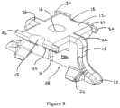
- FIG. 9 is a top perspective view of the clip of FIG. 7 ;
- FIG. 10 is a bottom perspective view of the clip of FIG. 7 ;
- FIG. 11 is a bottom elevation view of the clip of FIG. 7 ;
- FIG. 12 shows the clip of FIG. 7 during a typical installation attaching a leading deck plank to a support joist
- FIG. 13 shows a trailing plank installed adjacent the leading plank with spacing between
- FIG. 14 shows a strip of clips with preset elongate fasteners
- FIG. 15 shows a pair of strips with preset fasteners in a stacked configuration.
- a hidden deck clip for attaching grooved planks P to a support joist J is generally designated by reference numeral 10
- an associated strip of multiple clips joined together in a severable connection is designated by reference numeral 100 .
- Each clip 10 is configured to engage a groove G of the deck plank P and rests on the joist J, and an elongate fastener, such as a screw 34 , is driven through the clip 10 and into the joist J at a medial entry location to secure the deck plank to the joist.
- the clip 10 also acts to provide a preferred spacing between each attached leading deck plank and an adjacent trailing deck plank of the installation (see FIG. 12 ).
- the clip 10 is formed from a molded plastic material with high durability and strength.
- Each individual clip 10 is an integral molded member symmetric about two orthogonal planes which intersect along a vertical axis through a central opening 16 that extends through an upper base 12 .
- the opening is dimensioned to receive and guide a fastener so that upon proper positioning of the clip with respect to the joist J and the deck plank P, the fastener 34 is driven through the clip into the joist J at a preferred position.
- the upper portion of the opening 16 may have an outwardly tapered throat to receive the head of the fastener upon driving and ensure a surface-to-surface mating.
- the lower portion of the opening 16 forms opposed axially extending front and rear slots between opposite lateral legs 14 .
- the base 12 extends forwardly between front and rear edges, 12 a and 12 b , and laterally between opposite lateral edges.
- a leg 14 extends laterally outward and downward from each lateral edge, defining a laterally exposed shoulder 26 .
- Each leg 14 includes a substantially flat front surface 14 a and substantially flat rear surface 14 and a set of feet 22 at its bottom edge.
- the clip body 12 preferably has an upper planar surface a lower surface that carries a series of laterally spaced longitudinally extending ribs 24 .
- the ribs 24 are shown most clearly in FIGS. 8 , 10 and 11 .
- the opposite legs 14 are integral to the body 12 and extend laterally outward from the lateral edges and downward.
- the body 12 defines a front side that terminates at the front end 12 a and a substantially identical rear side that terminates at a rear end 12 b .
- Each of the front and rear sides of the body acts as a retainer and is contoured for reception into the groove G of a deck plank with the front or rear surface, 14 a or 14 b , in abutment with the lower nub of the plank.
- the ribs 24 When installed with a fastener driven through the opening 16 , the ribs 24 engage and typically penetrate the outer surface of the plank within the groove to provide rigidity and protect against lateral drift caused by temperature fluctuations and other factors. Additionally, an opposing pair of tabs 30 extends laterally outward from the base 12 at each of the front and rear ends, 12 a and 12 b , which assist in alignment and advancement of the clips 10 when installed using a tool with a feeding mechanism. Additionally, the front end 12 a and rear end 12 b each includes a semi-circular notch 18 .
- each clip 10 The respective notches 18 in each clip 10 are positioned in lateral alignment with one another such that, when multiple clips 10 are collated in a strip 100 , a rear end notch in a leading clip combines with a front end notch in the directly adjacent trailing clip to form a substantially circular hole 20 . See FIGS. 1 - 4 and 6 .
- the depicted preferred embodiment includes semi-circular notches that combine to form a circular opening; however, other geometries can be employed such as rectangular, ovular, or polygonal, provided that the opening is of sufficient size and configuration to pass an elongate fastener through.
- each leg 14 defines the spacing defines the proper spacing between adjacent deck planks of the installation. It will be appreciated that the sides are preferably essentially planar and parallel.
- Each leg 14 includes a set of outwardly extending feet 22 that combine to define a bottom mounting level. As shown in the Figures, each leg 14 carries two opposing longitudinally extending feet (one forward foot and one rearward foot) and one laterally outwardly extending foot that extends substantially perpendicularly to the longitudinal feet.
- the legs 14 are formed with a laterally inner undercut portion that defines a vertical clearance gap 28 . During assembly, the clearance gap 28 acts to prevent or minimize inadvertent uplift of the clip 10 as a screw is driven into the joist during installation.
- each of the laterally extending feet 22 hangs laterally outward over a respective opposite edge of the joist J.
- each foot 22 is coplanar with one another and forms a mounting level that is positioned on top of the support joist J during and after installation.
- the perpendicular nature of the feet is such that the clip 10 , and thus the base 12 , is maintained substantially level in all directions during installation.
- one or more clips 10 are installed with front side in the trailing groove G of a leading plank
- a trailing plank is positioned adjacent the leading plank with the rear side of the clip 10 within the front edge groove G, and the process is repeated to assemble a decking structure. See FIGS. 12 and 13 for reference.
- multiple clips 10 may be provided in a collated strip 100 , with adjacent clips 10 joined together in a severable front-to-rear relationship.
- a thin strip or strips 32 may be included in the mold of the strip 100 to join each clip together.
- the joining strips 32 are thin enough to allow an amount of flexion at the interface between adjacent clips.
- the strips are positioned laterally outside of the notches 18 so as not to obstruct the hole 20 .
- the collated strip 100 may be fed via a magazine or similar advancement element or mechanism automatically or by hand, whereby the frontmost clip 10 is maintained at a forward installation position and is severed from the adjacent clip in the strip 100 via the force of driving a fastener through the hole 16 .
- the magazine or advancement unit may include complementary elements, elements and/or surfaces to assist severing the clip when driven.
- an end clip may be detached by a user and installed as a singular standalone unit.
- a strip 100 ′ may be assembled with preset fasteners 34 in each clip hole 16 .
- the intermediate holes 20 formed between each clip 10 allow stacking of strips 100 in a longitudinally offset alignment with the top portions of preset fasteners extending through holes 20 in the strip directly above.
- FIG. 15 shows a pair of preset collated strips 100 ′ in such a stacked configuration.
- the clearance gap 28 at the lower end of the clips 10 has a lateral width dimension sufficient to accommodate the base 12 of a clip in the stacked configuration.
- the feet 22 are positioned entirely outside the lateral extent of the base 12 (i.e., no portion of the base overlies a foot).
- a clip for positioning and securing adjacent grooved planks to a joist comprising: a body extending longitudinally from a front end to a rear end and laterally between opposite lateral edges and defining a hole; a pair of legs, each leg extending downward from the body at a longitudinal position between the front end and rear end, wherein each of the front end and the rear end includes a notch in the edge between the opposite lateral edges.
- each of the legs defines a bottom placement surface and includes an undercut defining a gap between the bottom placement surfaces and the body.
- each leg carries a plurality of feet that define the bottom placement surface.
- each leg extends outward from a lateral edge of the body, thereby defining a shoulder.
- a clip as above comprising an elongate fastener held within the hole of the body.
- a strip of clips comprising a plurality of clips as above joined together in a front-rear relationship.
- a strip of clips as above wherein the front end of the body of each clip includes a front notch and the rear end of each clip includes a rear notch, wherein the front notch of a trailing clip is aligned with the rear notch of an adjacent leading clip to combine to form a pass through hole.
- a clip as above wherein the clip is mountable to a joist so that support surface rests on the joist and the front end of the body is received in a plank groove, and wherein a fastener driven through the hole in the body and into the joist secures the plank in position.
- a clip for positioning and securing adjacent grooved planks to a joist comprising: a body extending longitudinally from a front end to a rear end and laterally between opposite lateral edges; a pair of legs, each leg extending downward from the body at a longitudinal position between the front end and rear end, wherein each of the legs defines a bottom placement surface and includes an undercut defining a gap between the bottom placement surfaces and the body.
- a strip of clips comprising a plurality of clips as above joined together in a front-rear relationship.
- a clip as above wherein the clip is mountable to a joist so that support surface rests on the joist and the front end of the body is received in a plank groove, and wherein a fastener driven through the hole in the body and into the joist secures the plank in position.
- a clip for positioning and securing adjacent grooved planks to a joist comprising: a body extending longitudinally from a front end to a rear end and laterally between opposite lateral edges and defining a hole; a reference spacer extending laterally across the bottom side of the body at a longitudinal position between the front and rear edges, the reference spacer including an undercut portion at least as wide as the body.
- a strip of clips comprising a plurality of clips as above joined together in a front-rear relationship.
- a clip as above wherein the clip is mountable to a joist so that support surface rests on the joist and the front end of the body is received in a plank groove, and wherein a fastener driven through the hole in the body and into the joist secures the plank in position.
Abstract
Description
Claims (18)
Priority Applications (1)
| Application Number | Priority Date | Filing Date | Title |
|---|---|---|---|
| US17/213,389 US11873648B2 (en) | 2020-03-26 | 2021-03-26 | Deck clip |
Applications Claiming Priority (2)
| Application Number | Priority Date | Filing Date | Title |
|---|---|---|---|
| US202063000036P | 2020-03-26 | 2020-03-26 | |
| US17/213,389 US11873648B2 (en) | 2020-03-26 | 2021-03-26 | Deck clip |
Publications (2)
| Publication Number | Publication Date |
|---|---|
| US20210301543A1 US20210301543A1 (en) | 2021-09-30 |
| US11873648B2 true US11873648B2 (en) | 2024-01-16 |
Family
ID=75540050
Family Applications (1)
| Application Number | Title | Priority Date | Filing Date |
|---|---|---|---|
| US17/213,389 Active US11873648B2 (en) | 2020-03-26 | 2021-03-26 | Deck clip |
Country Status (5)
| Country | Link |
|---|---|
| US (1) | US11873648B2 (en) |
| AU (1) | AU2021242320A1 (en) |
| CA (1) | CA3172999A1 (en) |
| GB (1) | GB2608339A (en) |
| WO (1) | WO2021195462A1 (en) |
Families Citing this family (2)
| Publication number | Priority date | Publication date | Assignee | Title |
|---|---|---|---|---|
| US11359394B2 (en) * | 2019-03-27 | 2022-06-14 | Omg, Inc. | Alignment head for automatic fastener feed installation tool |
| US20220228373A1 (en) * | 2021-01-20 | 2022-07-21 | Pan American Screw Llc | Hidden deck fastener |
Citations (122)
| Publication number | Priority date | Publication date | Assignee | Title |
|---|---|---|---|---|
| US1714738A (en) * | 1928-06-11 | 1929-05-28 | Arthur R Smith | Flooring and the like |
| US2849715A (en) | 1953-02-03 | 1958-09-02 | Olin Mathieson | Fastener setting tool |
| US2886815A (en) | 1954-12-13 | 1959-05-19 | Powers Wire Products Company | Clip applicating gun |
| US2946060A (en) | 1958-04-07 | 1960-07-26 | Powers Wire Products Company I | Clip positioning head for fastener driving tool |
| US3181662A (en) | 1960-12-23 | 1965-05-04 | Jr Joseph N Maertzig | Mounting construction for chalk boards, corkboards and like panels |
| US3363817A (en) | 1964-11-20 | 1968-01-16 | Etem Ets | Explosively-actuated repeating-action power tool |
| US3473719A (en) | 1965-09-17 | 1969-10-21 | Sterling Eng Co Ltd | Cartridge-operated tools |
| US3633810A (en) | 1970-04-27 | 1972-01-11 | Kay Mfg Corp | Combined stapler and clipper for furniture spring clips |
| US3741455A (en) | 1968-11-20 | 1973-06-26 | Fastener Corp | Fastener driving tool |
| US3923227A (en) | 1973-12-13 | 1975-12-02 | Hilti Ag | Tapered seal between the barrel and drum type magazine in a fastening element setting gun |
| US3923226A (en) | 1973-12-13 | 1975-12-02 | Hilti Ag | Barrel and magazine alignment arrangement for a fastening element setting gun |
| US4339065A (en) | 1978-07-24 | 1982-07-13 | Haytayan Harry M | Pneumatic tool |
| US4424929A (en) | 1982-03-16 | 1984-01-10 | Power-Wire Fastener Systems, Inc. | Clip magazine feed for fastener driving tools |
| US4485952A (en) | 1982-06-03 | 1984-12-04 | Power-Line Fastener Systems, Inc. | Shiftable magazine clip feed for fastener driving tools |
| US4509668A (en) | 1981-10-24 | 1985-04-09 | Signode Corporation | Pneumatically operable fastener driving tool |
| US4809568A (en) | 1988-04-21 | 1989-03-07 | Demby Industries, Inc. | Barrel assembly for installation tool and method of installation |
| US5025968A (en) | 1989-06-19 | 1991-06-25 | Duo-Fast Corporation | Furniture tool |
| US5042142A (en) | 1989-02-15 | 1991-08-27 | Illinois Tool Works Inc. | Washer-dispensing and fastener-driving machine |
| US5238167A (en) | 1992-10-09 | 1993-08-24 | Illinois Tool Works Inc. | Positioning mechanism for powered fastener-driving tool |
| US5378102A (en) | 1991-09-30 | 1995-01-03 | Sfs Stadler, Inc. | Barrel assembly and composite stress plate |
| US5502942A (en) | 1993-09-16 | 1996-04-02 | Prince Corporation | Panel fastener |
| US5642597A (en) | 1996-06-21 | 1997-07-01 | Hendrickson; Gary J. | Drywall mounting bracket |
| US5713709A (en) * | 1996-06-25 | 1998-02-03 | Huang; Shih Chang | Screw stay suitable for use with screws of different screw heads |
| US5803338A (en) | 1996-11-26 | 1998-09-08 | Senco Products, Inc. | Fastener driving tool for locating a pre-existing hole in a first workpiece and driving a fastener therethrough into a second workpiece |
| US5931622A (en) * | 1997-10-07 | 1999-08-03 | Illinois Tool Works Inc. | Fastener assembly with lateral end extension |
| US6142352A (en) | 1998-05-05 | 2000-11-07 | Illinois Tool Works Inc. | Roofing washer-dispensing and fastener-driving machine |
| US6273316B1 (en) | 1997-04-24 | 2001-08-14 | Alfonso Losada | Fastener feeding system for power actuated gun |
| US6314699B1 (en) | 1999-01-15 | 2001-11-13 | Kroy Building Products, Inc. | Deck system with deck clip |
| US20020059766A1 (en) | 1999-07-19 | 2002-05-23 | Gregori Karl H. W. | Decking assembly and decking kit with hold-down clip |
| US6402415B1 (en) | 1997-03-05 | 2002-06-11 | Eberle, Iii Harry W. | Anchoring biscuit device |
| US20030121226A1 (en) | 2001-07-25 | 2003-07-03 | Manuel Bolduc | Method for installing wood flooring |
| US6598775B1 (en) | 2002-08-30 | 2003-07-29 | Tung-Hsien Chen | Hammer head assembly for power hammer |
| US6711809B1 (en) | 2000-05-31 | 2004-03-30 | Illinois Tool Works Inc. | Pneumatic and manual installation tools for installing U-nut fasteners |
| US6761299B2 (en) | 2002-09-18 | 2004-07-13 | Illinois Tool Works Inc. | Magazine clutch assembly |
| US6779697B2 (en) | 2002-08-26 | 2004-08-24 | Wang-Kuan Lin | Pneumatic nailer with rotatable and movable magazine |
| US6810633B2 (en) * | 2002-08-02 | 2004-11-02 | G. Steven Harris, Sr. | Deck board fastener |
| US20050028473A1 (en) | 2003-08-05 | 2005-02-10 | Martin Grohman | Hidden deck fastener system |
| US20050063771A1 (en) * | 2003-09-23 | 2005-03-24 | Harris G. Steven | Resilient deck board fastener |
| US6871467B2 (en) | 2002-09-06 | 2005-03-29 | Robert Hafner | Decking system with clip apparatus |
| US6908022B2 (en) | 2000-01-13 | 2005-06-21 | Jeffrey F. Schmitz | Washer feeding and positioning attachment for fastener driver |
| US6932261B2 (en) | 2003-03-31 | 2005-08-23 | Besco Pneumatic Corp. | Palm operated nail ejector |
| US20060059822A1 (en) | 2004-08-04 | 2006-03-23 | Guffey James K | Deck clip |
| US7111767B2 (en) | 1997-04-24 | 2006-09-26 | Simpson Strong-Tie Company, Inc. | Power actuated fastener system |
| US7287681B1 (en) | 2006-07-20 | 2007-10-30 | De Poan Pneumatic Corp. | Palm nailer |
| US20070289249A1 (en) | 2006-06-16 | 2007-12-20 | David Martel | L-shape slotted deck board and hidden fastener system |
| US7516841B2 (en) * | 2003-09-19 | 2009-04-14 | Illinois Tool Works Inc. | Connecting fastener and fastener holder |
| US7546717B2 (en) | 2004-03-03 | 2009-06-16 | Complepark, S.L. | Timber covering for exteriors and interiors |
| US7644556B2 (en) | 2007-11-15 | 2010-01-12 | Correct Building Products, L.L.C. | Planking system and method |
| USD612708S1 (en) | 2008-10-24 | 2010-03-30 | James Fattori | Multi-angle bracket |
| USD612709S1 (en) | 2008-10-24 | 2010-03-30 | James Fattori | Multi-angle bracket |
| US20100083610A1 (en) | 2008-10-02 | 2010-04-08 | Robert King | Installation pilot device and method |
| USD613593S1 (en) | 2008-08-01 | 2010-04-13 | Fiber Composites, Llc | Installation pilot device |
| US7739807B2 (en) | 2008-05-09 | 2010-06-22 | Kevin Anthony Grant | Siding gauge device for staple gun |
| US7805902B2 (en) | 2006-03-23 | 2010-10-05 | Tiger Claw, Inc. | Fastener for grooved or slotted decking members |
| USD625989S1 (en) | 2009-10-09 | 2010-10-26 | Fiber Composites, Llc | Baluster connector |
| USD629284S1 (en) | 2009-09-25 | 2010-12-21 | Fiber Composites, Llc | Baluster connector |
| USD632164S1 (en) | 2009-11-20 | 2011-02-08 | Fiber Composites, Llc | Installation pilot device |
| US7882994B2 (en) | 2006-01-05 | 2011-02-08 | Illinois Tool Works Inc. | 45 degree adjustable adapter for flooring nailer |
| US7908812B2 (en) | 2002-01-03 | 2011-03-22 | Eberle Harry W Iii | Decking system and anchoring device |
| US7908816B2 (en) | 2003-03-24 | 2011-03-22 | Kronotec Ag | Device for connecting building boards, especially floor panels |
| US20110073824A1 (en) | 2009-09-25 | 2011-03-31 | Lappin Rick A | Railing system and coupling element and methods of assembly |
| US7984599B2 (en) * | 2006-10-09 | 2011-07-26 | Building Materials Investment Corporation | Hidden decking fastener and related method of fastening deck boards |
| USD643706S1 (en) | 2010-07-30 | 2011-08-23 | Fiber Composites, Llc | Baluster connector |
| USD643707S1 (en) | 2010-07-30 | 2011-08-23 | Fiber Composites, Llc | Baluster connector |
| US8011153B2 (en) | 2009-02-13 | 2011-09-06 | Brian Keith Orchard | Deck fastener and method of use |
| US8146303B2 (en) * | 2009-09-21 | 2012-04-03 | Brent Alan Gibson | Integrated decking member fastening track |
| US8158044B2 (en) | 2005-11-04 | 2012-04-17 | Integrity Composites, LLC | Method of forming composite articles |
| US8161702B2 (en) | 2003-03-20 | 2012-04-24 | Blue Heron Enterprises Llc | Expansion-compensating deck fastener |
| US20120110944A1 (en) | 2010-11-10 | 2012-05-10 | Hess Joseph L | Fastener for building materials |
| US8256614B1 (en) | 2006-09-25 | 2012-09-04 | Wadsworth Sr Keven R | Interconnected and on-site severable deck clips with cooperating installation tool for joining two adjacent decking planks to an underlying support structure |
| US20130025228A1 (en) * | 2011-07-13 | 2013-01-31 | A. Raymond Et Cie | Decking system with hidden dovetail fastener |
| US8376203B2 (en) | 2009-01-16 | 2013-02-19 | Omg, Inc. | Apparatus and method for rapid installation of hidden deck plank fasteners |
| US8393125B2 (en) | 2010-02-18 | 2013-03-12 | Omg, Inc. | Hidden fastener for deck planks with undercut side grooves |
| US8534526B2 (en) | 2010-01-19 | 2013-09-17 | Brian Keith Orchard | Clip guide installation apparatus |
| US8555570B2 (en) | 2010-06-25 | 2013-10-15 | Omg, Inc. | Hidden fastener formed in situ during attachment of sheathing onto a support member |
| US8672600B2 (en) * | 2008-02-07 | 2014-03-18 | Tinnerman Palnut Engineered Products, Inc. | Deck clip |
| US20140174025A1 (en) | 2011-07-08 | 2014-06-26 | Upm-Kymmene Corporation | Fastening member for elements, a method and a system for manufacturing a fastening member, and an arrangement wherein elements are fastened using a fastening member |
| US20140186109A1 (en) * | 2009-11-25 | 2014-07-03 | Kevin Wadsworth | Method for making a gangable composite clip for attaching decking |
| US20150044434A1 (en) | 2014-10-28 | 2015-02-12 | Fiber Composites, Llc | Systems and Methods for Generating Surface Patterns on Composite Building Materials |
| US20150128520A1 (en) * | 2013-09-16 | 2015-05-14 | Connor Sports Flooring, Llc | Flooring Surface Integrated With Interlocking Plastic Base |
| US9073295B2 (en) | 2008-12-19 | 2015-07-07 | Fiber Composites, Llc | Wood-plastic composites utilizing ionomer capstocks and methods of manufacture |
| US9145673B1 (en) | 2014-11-25 | 2015-09-29 | Hugh A. Dantzer | Deck clip and modular deck assembly |
| US9181715B2 (en) | 2011-10-27 | 2015-11-10 | Brian Keith Orchard | Clip device for attaching structural member to a supporting structure |
| US9205536B2 (en) | 2013-10-30 | 2015-12-08 | Brett Clark | Spacing means |
| US20150354204A1 (en) | 2013-02-22 | 2015-12-10 | Upm-Kymmene Corporation | A Fastening Member for Fastening Elongated Terrace Elements and an Arrangement Comprising the Same |
| US9216847B2 (en) * | 2012-05-16 | 2015-12-22 | Handy & Harman | Container and lid with fastener alignment guide |
| US9290889B2 (en) | 2011-01-25 | 2016-03-22 | Young Doo Choo | Deck fastening device |
| USD759471S1 (en) * | 2013-10-18 | 2016-06-21 | Elmich Pte Ltd. | Fastener for decking |
| US9416546B2 (en) | 2012-01-24 | 2016-08-16 | Mark Claudin | Deck installation track and method |
| US20160362902A1 (en) | 2015-06-15 | 2016-12-15 | Elmich Pte Ltd | Fastening system for decking boards |
| US9555529B2 (en) | 2012-11-16 | 2017-01-31 | Fasco S.R.L. | Device for applying fastening means |
| US20170106513A1 (en) | 2015-10-16 | 2017-04-20 | Brian Keith Orchard | Deck clip magazine |
| US9637934B2 (en) | 2009-11-25 | 2017-05-02 | Simpson Strong-Tie Company Inc. | Gangable composite deck clip |
| USD792757S1 (en) | 2016-06-20 | 2017-07-25 | Simpson Strong-Tie Company Inc. | Deck board fastener |
| USD795049S1 (en) | 2016-06-20 | 2017-08-22 | Simpson Strong-Tie Company Inc. | Deck board fastener |
| US9850667B2 (en) | 2015-08-24 | 2017-12-26 | Valinge Innovation Ab | Panel with a fastening device |
| US9963886B2 (en) | 2015-08-03 | 2018-05-08 | Royal Group, Inc. | Hidden board anchor |
| US20180223547A1 (en) | 2017-02-06 | 2018-08-09 | MN Fastener LLC | Hidden clip and fastening system for decking |
| US20180238060A1 (en) * | 2017-02-21 | 2018-08-23 | Klevaklip Systems Pty Ltd. | Decking clip |
| US10113306B2 (en) | 2016-06-20 | 2018-10-30 | Simpson Strong-Tie Company Inc. | Deck board fasteners |
| US10145404B2 (en) * | 2016-07-11 | 2018-12-04 | Omg, Inc. | Fastener with preset securing member |
| US10174496B2 (en) | 2016-10-21 | 2019-01-08 | Liv Building Products Inc. | Deck bracket |
| US20190048578A1 (en) | 2016-01-28 | 2019-02-14 | Nicholas W. Emerson | Bracket for securing decking member |
| US20190055974A1 (en) | 2017-08-15 | 2019-02-21 | National Nail Corp. | Hidden fastener unit and related method of use |
| US20190055738A1 (en) | 2017-08-15 | 2019-02-21 | National Nail Corp. | Hidden fastener unit and related method of use |
| US10214896B2 (en) | 2014-06-20 | 2019-02-26 | Glenn J. Tebo | Decking clip |
| US20190071880A1 (en) | 2017-02-06 | 2019-03-07 | MN Fastener LLC | Hidden clip and fastening system for decking |
| US20190112822A1 (en) * | 2013-06-14 | 2019-04-18 | Phillip Busby | Flooring Support System |
| US20190136546A1 (en) | 2017-11-03 | 2019-05-09 | Klevaklip Systems Pty Ltd. | Decking clip |
| USD850897S1 (en) | 2018-05-18 | 2019-06-11 | National Nail Corp. | Fastener positioning device |
| US10315295B2 (en) | 2010-01-13 | 2019-06-11 | National Nail Corp. | Fastener, installation tool and related method of use |
| US20190186130A1 (en) * | 2017-12-18 | 2019-06-20 | ZomeTek, LLC | Plank connectors |
| US20190211856A1 (en) | 2018-01-05 | 2019-07-11 | Nova USA Wood Products, LLC | Resilient mounting clips, panel mount systems including the same, and associated methods |
| USD853829S1 (en) | 2018-06-01 | 2019-07-16 | National Nail Corp. | Fastener positioning device |
| US20190271161A1 (en) | 2018-03-02 | 2019-09-05 | eGlass, LLC | Hidden fastener railing system |
| US20190284796A1 (en) | 2016-11-10 | 2019-09-19 | Pdmm Limited, As Trustee Of The Pdmm Trust | Deck connector |
| US20190309527A1 (en) | 2016-12-16 | 2019-10-10 | Välinge Innovation AB | A set of decking boards provided with a connecting system |
| US10487460B2 (en) | 2018-02-14 | 2019-11-26 | Kyeong Jun LEE | Deck module including quick clip module |
| US20190360214A1 (en) | 2017-08-15 | 2019-11-28 | National Nail Corp. | Hidden fastener unit and related method of use |
| US20200087925A1 (en) | 2017-08-15 | 2020-03-19 | National Nail Corp. | Hidden fastener unit and related method of use |
| US20200217084A1 (en) * | 2019-01-08 | 2020-07-09 | Välinge Innovation AB | Flooring system provided with a connecting system and an associated connecting device |
| US20200340252A1 (en) * | 2019-04-23 | 2020-10-29 | Omg, Inc. | Hidden Fastener Assembly for Attaching Grooved Deck Members |
-
2021
- 2021-03-26 WO PCT/US2021/024287 patent/WO2021195462A1/en active Application Filing
- 2021-03-26 GB GB2214000.8A patent/GB2608339A/en active Pending
- 2021-03-26 CA CA3172999A patent/CA3172999A1/en active Pending
- 2021-03-26 US US17/213,389 patent/US11873648B2/en active Active
- 2021-03-26 AU AU2021242320A patent/AU2021242320A1/en active Pending
Patent Citations (132)
| Publication number | Priority date | Publication date | Assignee | Title |
|---|---|---|---|---|
| US1714738A (en) * | 1928-06-11 | 1929-05-28 | Arthur R Smith | Flooring and the like |
| US2849715A (en) | 1953-02-03 | 1958-09-02 | Olin Mathieson | Fastener setting tool |
| US2886815A (en) | 1954-12-13 | 1959-05-19 | Powers Wire Products Company | Clip applicating gun |
| US2946060A (en) | 1958-04-07 | 1960-07-26 | Powers Wire Products Company I | Clip positioning head for fastener driving tool |
| US3181662A (en) | 1960-12-23 | 1965-05-04 | Jr Joseph N Maertzig | Mounting construction for chalk boards, corkboards and like panels |
| US3363817A (en) | 1964-11-20 | 1968-01-16 | Etem Ets | Explosively-actuated repeating-action power tool |
| US3473719A (en) | 1965-09-17 | 1969-10-21 | Sterling Eng Co Ltd | Cartridge-operated tools |
| US3741455A (en) | 1968-11-20 | 1973-06-26 | Fastener Corp | Fastener driving tool |
| US3633810A (en) | 1970-04-27 | 1972-01-11 | Kay Mfg Corp | Combined stapler and clipper for furniture spring clips |
| US3923227A (en) | 1973-12-13 | 1975-12-02 | Hilti Ag | Tapered seal between the barrel and drum type magazine in a fastening element setting gun |
| US3923226A (en) | 1973-12-13 | 1975-12-02 | Hilti Ag | Barrel and magazine alignment arrangement for a fastening element setting gun |
| US4339065A (en) | 1978-07-24 | 1982-07-13 | Haytayan Harry M | Pneumatic tool |
| US4509668A (en) | 1981-10-24 | 1985-04-09 | Signode Corporation | Pneumatically operable fastener driving tool |
| US4424929A (en) | 1982-03-16 | 1984-01-10 | Power-Wire Fastener Systems, Inc. | Clip magazine feed for fastener driving tools |
| US4485952A (en) | 1982-06-03 | 1984-12-04 | Power-Line Fastener Systems, Inc. | Shiftable magazine clip feed for fastener driving tools |
| US4809568A (en) | 1988-04-21 | 1989-03-07 | Demby Industries, Inc. | Barrel assembly for installation tool and method of installation |
| US5042142A (en) | 1989-02-15 | 1991-08-27 | Illinois Tool Works Inc. | Washer-dispensing and fastener-driving machine |
| US5025968A (en) | 1989-06-19 | 1991-06-25 | Duo-Fast Corporation | Furniture tool |
| US5378102A (en) | 1991-09-30 | 1995-01-03 | Sfs Stadler, Inc. | Barrel assembly and composite stress plate |
| US5238167A (en) | 1992-10-09 | 1993-08-24 | Illinois Tool Works Inc. | Positioning mechanism for powered fastener-driving tool |
| US5502942A (en) | 1993-09-16 | 1996-04-02 | Prince Corporation | Panel fastener |
| US5642597A (en) | 1996-06-21 | 1997-07-01 | Hendrickson; Gary J. | Drywall mounting bracket |
| US5713709A (en) * | 1996-06-25 | 1998-02-03 | Huang; Shih Chang | Screw stay suitable for use with screws of different screw heads |
| US5803338A (en) | 1996-11-26 | 1998-09-08 | Senco Products, Inc. | Fastener driving tool for locating a pre-existing hole in a first workpiece and driving a fastener therethrough into a second workpiece |
| US6402415B1 (en) | 1997-03-05 | 2002-06-11 | Eberle, Iii Harry W. | Anchoring biscuit device |
| US7111767B2 (en) | 1997-04-24 | 2006-09-26 | Simpson Strong-Tie Company, Inc. | Power actuated fastener system |
| US6273316B1 (en) | 1997-04-24 | 2001-08-14 | Alfonso Losada | Fastener feeding system for power actuated gun |
| US5931622A (en) * | 1997-10-07 | 1999-08-03 | Illinois Tool Works Inc. | Fastener assembly with lateral end extension |
| US6142352A (en) | 1998-05-05 | 2000-11-07 | Illinois Tool Works Inc. | Roofing washer-dispensing and fastener-driving machine |
| US6314699B1 (en) | 1999-01-15 | 2001-11-13 | Kroy Building Products, Inc. | Deck system with deck clip |
| US20020059766A1 (en) | 1999-07-19 | 2002-05-23 | Gregori Karl H. W. | Decking assembly and decking kit with hold-down clip |
| US6908022B2 (en) | 2000-01-13 | 2005-06-21 | Jeffrey F. Schmitz | Washer feeding and positioning attachment for fastener driver |
| US6711809B1 (en) | 2000-05-31 | 2004-03-30 | Illinois Tool Works Inc. | Pneumatic and manual installation tools for installing U-nut fasteners |
| US20030121226A1 (en) | 2001-07-25 | 2003-07-03 | Manuel Bolduc | Method for installing wood flooring |
| US7908812B2 (en) | 2002-01-03 | 2011-03-22 | Eberle Harry W Iii | Decking system and anchoring device |
| US9228362B2 (en) | 2002-01-03 | 2016-01-05 | Blue Heron Enterprise LLC | Decking system and anchoring device |
| US6810633B2 (en) * | 2002-08-02 | 2004-11-02 | G. Steven Harris, Sr. | Deck board fastener |
| US6779697B2 (en) | 2002-08-26 | 2004-08-24 | Wang-Kuan Lin | Pneumatic nailer with rotatable and movable magazine |
| US6598775B1 (en) | 2002-08-30 | 2003-07-29 | Tung-Hsien Chen | Hammer head assembly for power hammer |
| US6871467B2 (en) | 2002-09-06 | 2005-03-29 | Robert Hafner | Decking system with clip apparatus |
| US6761299B2 (en) | 2002-09-18 | 2004-07-13 | Illinois Tool Works Inc. | Magazine clutch assembly |
| US8161702B2 (en) | 2003-03-20 | 2012-04-24 | Blue Heron Enterprises Llc | Expansion-compensating deck fastener |
| US7908816B2 (en) | 2003-03-24 | 2011-03-22 | Kronotec Ag | Device for connecting building boards, especially floor panels |
| US6932261B2 (en) | 2003-03-31 | 2005-08-23 | Besco Pneumatic Corp. | Palm operated nail ejector |
| US20050028473A1 (en) | 2003-08-05 | 2005-02-10 | Martin Grohman | Hidden deck fastener system |
| US7516841B2 (en) * | 2003-09-19 | 2009-04-14 | Illinois Tool Works Inc. | Connecting fastener and fastener holder |
| US7052200B2 (en) | 2003-09-23 | 2006-05-30 | Harris G Steven | Resilient deck board fastener |
| US20050063771A1 (en) * | 2003-09-23 | 2005-03-24 | Harris G. Steven | Resilient deck board fastener |
| US7546717B2 (en) | 2004-03-03 | 2009-06-16 | Complepark, S.L. | Timber covering for exteriors and interiors |
| US20060059822A1 (en) | 2004-08-04 | 2006-03-23 | Guffey James K | Deck clip |
| US8158044B2 (en) | 2005-11-04 | 2012-04-17 | Integrity Composites, LLC | Method of forming composite articles |
| US7882994B2 (en) | 2006-01-05 | 2011-02-08 | Illinois Tool Works Inc. | 45 degree adjustable adapter for flooring nailer |
| US7805902B2 (en) | 2006-03-23 | 2010-10-05 | Tiger Claw, Inc. | Fastener for grooved or slotted decking members |
| US20070289249A1 (en) | 2006-06-16 | 2007-12-20 | David Martel | L-shape slotted deck board and hidden fastener system |
| US7287681B1 (en) | 2006-07-20 | 2007-10-30 | De Poan Pneumatic Corp. | Palm nailer |
| US8256614B1 (en) | 2006-09-25 | 2012-09-04 | Wadsworth Sr Keven R | Interconnected and on-site severable deck clips with cooperating installation tool for joining two adjacent decking planks to an underlying support structure |
| US7984599B2 (en) * | 2006-10-09 | 2011-07-26 | Building Materials Investment Corporation | Hidden decking fastener and related method of fastening deck boards |
| US7644556B2 (en) | 2007-11-15 | 2010-01-12 | Correct Building Products, L.L.C. | Planking system and method |
| US8672600B2 (en) * | 2008-02-07 | 2014-03-18 | Tinnerman Palnut Engineered Products, Inc. | Deck clip |
| US7739807B2 (en) | 2008-05-09 | 2010-06-22 | Kevin Anthony Grant | Siding gauge device for staple gun |
| USD613593S1 (en) | 2008-08-01 | 2010-04-13 | Fiber Composites, Llc | Installation pilot device |
| US20100083610A1 (en) | 2008-10-02 | 2010-04-08 | Robert King | Installation pilot device and method |
| USD612709S1 (en) | 2008-10-24 | 2010-03-30 | James Fattori | Multi-angle bracket |
| USD612708S1 (en) | 2008-10-24 | 2010-03-30 | James Fattori | Multi-angle bracket |
| US9073295B2 (en) | 2008-12-19 | 2015-07-07 | Fiber Composites, Llc | Wood-plastic composites utilizing ionomer capstocks and methods of manufacture |
| US8376203B2 (en) | 2009-01-16 | 2013-02-19 | Omg, Inc. | Apparatus and method for rapid installation of hidden deck plank fasteners |
| US8011153B2 (en) | 2009-02-13 | 2011-09-06 | Brian Keith Orchard | Deck fastener and method of use |
| US8146303B2 (en) * | 2009-09-21 | 2012-04-03 | Brent Alan Gibson | Integrated decking member fastening track |
| USD629284S1 (en) | 2009-09-25 | 2010-12-21 | Fiber Composites, Llc | Baluster connector |
| US20110073824A1 (en) | 2009-09-25 | 2011-03-31 | Lappin Rick A | Railing system and coupling element and methods of assembly |
| USD625989S1 (en) | 2009-10-09 | 2010-10-26 | Fiber Composites, Llc | Baluster connector |
| USD632164S1 (en) | 2009-11-20 | 2011-02-08 | Fiber Composites, Llc | Installation pilot device |
| US9868147B2 (en) | 2009-11-25 | 2018-01-16 | Simpson Strong-Tie Company Inc. | Method of making composite deck clips |
| US9637934B2 (en) | 2009-11-25 | 2017-05-02 | Simpson Strong-Tie Company Inc. | Gangable composite deck clip |
| US9700931B2 (en) | 2009-11-25 | 2017-07-11 | Simpson Strong-Tie Company Inc. | Methods of making a clip for attaching decking |
| US20140186109A1 (en) * | 2009-11-25 | 2014-07-03 | Kevin Wadsworth | Method for making a gangable composite clip for attaching decking |
| US10315295B2 (en) | 2010-01-13 | 2019-06-11 | National Nail Corp. | Fastener, installation tool and related method of use |
| US8534526B2 (en) | 2010-01-19 | 2013-09-17 | Brian Keith Orchard | Clip guide installation apparatus |
| US8393125B2 (en) | 2010-02-18 | 2013-03-12 | Omg, Inc. | Hidden fastener for deck planks with undercut side grooves |
| US8555570B2 (en) | 2010-06-25 | 2013-10-15 | Omg, Inc. | Hidden fastener formed in situ during attachment of sheathing onto a support member |
| USD643706S1 (en) | 2010-07-30 | 2011-08-23 | Fiber Composites, Llc | Baluster connector |
| USD643707S1 (en) | 2010-07-30 | 2011-08-23 | Fiber Composites, Llc | Baluster connector |
| US20120110944A1 (en) | 2010-11-10 | 2012-05-10 | Hess Joseph L | Fastener for building materials |
| US9290889B2 (en) | 2011-01-25 | 2016-03-22 | Young Doo Choo | Deck fastening device |
| US20140174025A1 (en) | 2011-07-08 | 2014-06-26 | Upm-Kymmene Corporation | Fastening member for elements, a method and a system for manufacturing a fastening member, and an arrangement wherein elements are fastened using a fastening member |
| US20130025228A1 (en) * | 2011-07-13 | 2013-01-31 | A. Raymond Et Cie | Decking system with hidden dovetail fastener |
| US9181715B2 (en) | 2011-10-27 | 2015-11-10 | Brian Keith Orchard | Clip device for attaching structural member to a supporting structure |
| US9416546B2 (en) | 2012-01-24 | 2016-08-16 | Mark Claudin | Deck installation track and method |
| US9216847B2 (en) * | 2012-05-16 | 2015-12-22 | Handy & Harman | Container and lid with fastener alignment guide |
| US9555529B2 (en) | 2012-11-16 | 2017-01-31 | Fasco S.R.L. | Device for applying fastening means |
| US20150354204A1 (en) | 2013-02-22 | 2015-12-10 | Upm-Kymmene Corporation | A Fastening Member for Fastening Elongated Terrace Elements and an Arrangement Comprising the Same |
| US20190112822A1 (en) * | 2013-06-14 | 2019-04-18 | Phillip Busby | Flooring Support System |
| US20150128520A1 (en) * | 2013-09-16 | 2015-05-14 | Connor Sports Flooring, Llc | Flooring Surface Integrated With Interlocking Plastic Base |
| USD759471S1 (en) * | 2013-10-18 | 2016-06-21 | Elmich Pte Ltd. | Fastener for decking |
| US9205536B2 (en) | 2013-10-30 | 2015-12-08 | Brett Clark | Spacing means |
| US10407898B2 (en) | 2014-06-20 | 2019-09-10 | Glenn J. Tebo | Decking clip |
| US10214896B2 (en) | 2014-06-20 | 2019-02-26 | Glenn J. Tebo | Decking clip |
| US20150044434A1 (en) | 2014-10-28 | 2015-02-12 | Fiber Composites, Llc | Systems and Methods for Generating Surface Patterns on Composite Building Materials |
| US9145673B1 (en) | 2014-11-25 | 2015-09-29 | Hugh A. Dantzer | Deck clip and modular deck assembly |
| US20160362902A1 (en) | 2015-06-15 | 2016-12-15 | Elmich Pte Ltd | Fastening system for decking boards |
| US9963886B2 (en) | 2015-08-03 | 2018-05-08 | Royal Group, Inc. | Hidden board anchor |
| US9850667B2 (en) | 2015-08-24 | 2017-12-26 | Valinge Innovation Ab | Panel with a fastening device |
| US20170106513A1 (en) | 2015-10-16 | 2017-04-20 | Brian Keith Orchard | Deck clip magazine |
| US20190048578A1 (en) | 2016-01-28 | 2019-02-14 | Nicholas W. Emerson | Bracket for securing decking member |
| US20190112802A1 (en) | 2016-06-20 | 2019-04-18 | Simpson Strong-Tie Company Inc. | Deck board fastener methods |
| US10113306B2 (en) | 2016-06-20 | 2018-10-30 | Simpson Strong-Tie Company Inc. | Deck board fasteners |
| USD792757S1 (en) | 2016-06-20 | 2017-07-25 | Simpson Strong-Tie Company Inc. | Deck board fastener |
| US10309099B2 (en) | 2016-06-20 | 2019-06-04 | Simpson Strong-Tie Company Inc. | Deck board fastener methods |
| USD795049S1 (en) | 2016-06-20 | 2017-08-22 | Simpson Strong-Tie Company Inc. | Deck board fastener |
| US10145404B2 (en) * | 2016-07-11 | 2018-12-04 | Omg, Inc. | Fastener with preset securing member |
| US10174496B2 (en) | 2016-10-21 | 2019-01-08 | Liv Building Products Inc. | Deck bracket |
| US20190136502A1 (en) | 2016-10-21 | 2019-05-09 | Liv Building Products Inc. | Deck bracket |
| US20190284796A1 (en) | 2016-11-10 | 2019-09-19 | Pdmm Limited, As Trustee Of The Pdmm Trust | Deck connector |
| US20190309527A1 (en) | 2016-12-16 | 2019-10-10 | Välinge Innovation AB | A set of decking boards provided with a connecting system |
| US20190071880A1 (en) | 2017-02-06 | 2019-03-07 | MN Fastener LLC | Hidden clip and fastening system for decking |
| US20180223547A1 (en) | 2017-02-06 | 2018-08-09 | MN Fastener LLC | Hidden clip and fastening system for decking |
| US20180238060A1 (en) * | 2017-02-21 | 2018-08-23 | Klevaklip Systems Pty Ltd. | Decking clip |
| US20190055738A1 (en) | 2017-08-15 | 2019-02-21 | National Nail Corp. | Hidden fastener unit and related method of use |
| US20190360214A1 (en) | 2017-08-15 | 2019-11-28 | National Nail Corp. | Hidden fastener unit and related method of use |
| US20200362570A1 (en) | 2017-08-15 | 2020-11-19 | National Nail Corp. | Hidden fastener unit and related method of use |
| US20200087925A1 (en) | 2017-08-15 | 2020-03-19 | National Nail Corp. | Hidden fastener unit and related method of use |
| US10378218B2 (en) | 2017-08-15 | 2019-08-13 | National Nail Corp. | Hidden fastener unit and related method of use |
| US20190055974A1 (en) | 2017-08-15 | 2019-02-21 | National Nail Corp. | Hidden fastener unit and related method of use |
| US20190136546A1 (en) | 2017-11-03 | 2019-05-09 | Klevaklip Systems Pty Ltd. | Decking clip |
| US20190186130A1 (en) * | 2017-12-18 | 2019-06-20 | ZomeTek, LLC | Plank connectors |
| US20190211856A1 (en) | 2018-01-05 | 2019-07-11 | Nova USA Wood Products, LLC | Resilient mounting clips, panel mount systems including the same, and associated methods |
| US10487460B2 (en) | 2018-02-14 | 2019-11-26 | Kyeong Jun LEE | Deck module including quick clip module |
| US20190271161A1 (en) | 2018-03-02 | 2019-09-05 | eGlass, LLC | Hidden fastener railing system |
| USD850897S1 (en) | 2018-05-18 | 2019-06-11 | National Nail Corp. | Fastener positioning device |
| USD853829S1 (en) | 2018-06-01 | 2019-07-16 | National Nail Corp. | Fastener positioning device |
| US20200217084A1 (en) * | 2019-01-08 | 2020-07-09 | Välinge Innovation AB | Flooring system provided with a connecting system and an associated connecting device |
| US20200340252A1 (en) * | 2019-04-23 | 2020-10-29 | Omg, Inc. | Hidden Fastener Assembly for Attaching Grooved Deck Members |
Non-Patent Citations (7)
| Title |
|---|
| "Coyote Clip Hidden Fasteners—Pan American Screw," retrieved from http://www.panamericanscrew.com/products/BROWSE_BRAND/SURE_DRIVE/HIDDEN_DECK_FASTENERS/COYOTE_CLIP_HIDDEN_DECK_FASTENER/, Dec. 12, 2018. |
| "Coyote Clip Installation Instructions," retrieved before Mar. 26, 2020. |
| "Discover the hidden beauty of Hidden Deck Fasteners," retrieved from http://www.panamericanscrew.com/products/BROWSE_BRAND/SURE_DRIVE/HIDDEN_DECK_FASTENERS.aspx, Dec. 12, 2018. |
| "Hidden Fasteners and Composite Saw Blades," retrieved from https://www.trex.com/products/accessory-hardware/, Dec. 12, 2018. |
| "TurboClip Universal Hidden Fastener ¼″ Deck Clip for Composite Grooved Boards," retrieved from https://www.ebay.com/itm/TurboClip-Universal-Hidden-Fastener-1-4-Deck-Clip-for-Composite-Grooved-Boards-/352715465168, Jan. 9, 2020. |
| "TurboClip. Universal Hidden Deck Clip," retrieved Feb. 5, 2019. |
| International Search Report and Written Opinion dated Jul. 5, 2021 for International Patent Application No. PCT/US2021/024287. |
Also Published As
| Publication number | Publication date |
|---|---|
| CA3172999A1 (en) | 2021-09-30 |
| WO2021195462A1 (en) | 2021-09-30 |
| GB2608339A (en) | 2022-12-28 |
| AU2021242320A1 (en) | 2022-10-06 |
| US20210301543A1 (en) | 2021-09-30 |
| GB202214000D0 (en) | 2022-11-09 |
Similar Documents
| Publication | Publication Date | Title |
|---|---|---|
| US11873648B2 (en) | Deck clip | |
| US10494821B2 (en) | Universal fastener for decking | |
| CA2887472C (en) | Universal fastener for decking | |
| US8966857B2 (en) | Saddle hanger for a structure | |
| US9003624B2 (en) | Method for making a gangable composite clip for attaching decking | |
| US20100212245A1 (en) | Fastening Plate for Grooved Decking Boards | |
| US10920432B2 (en) | Hidden clip and fastening system for decking | |
| US5564248A (en) | Construction hanger and method of making the same | |
| US11359383B2 (en) | Hidden fastener assembly for attaching grooved deck members | |
| US20230148009A1 (en) | Hidden clip and fastening system for decking | |
| GB2561679A (en) | A decking clip | |
| US9458635B1 (en) | Stringer for decking | |
| AU2007278768B2 (en) | A connector | |
| US20110123290A1 (en) | Gangable composite clip for attaching decking and method for making | |
| CN110121582B (en) | Panel connector | |
| KR20060090975A (en) | Floor | |
| US3235920A (en) | Toothed spline joint | |
| WO2019040301A1 (en) | Interlocking fastening clips | |
| KR20180033543A (en) | A descendent structure of a hat-shaped steel sheet file, a descendent hat-shaped steel sheet file unit, | |
| US20090217606A1 (en) | Joining panels of sheet material | |
| CA2997072A1 (en) | Tension bracket |
Legal Events
| Date | Code | Title | Description |
|---|---|---|---|
| AS | Assignment |
Owner name: OMG, INC., MASSACHUSETTS Free format text: ASSIGNMENT OF ASSIGNORS INTEREST;ASSIGNORS:CARLSON, LOGAN;KRAUCUNAS, MITCHELL T.;ENKO, FREDERICK A.;AND OTHERS;SIGNING DATES FROM 20200331 TO 20200831;REEL/FRAME:055729/0062 |
|
| FEPP | Fee payment procedure |
Free format text: ENTITY STATUS SET TO UNDISCOUNTED (ORIGINAL EVENT CODE: BIG.); ENTITY STATUS OF PATENT OWNER: LARGE ENTITY |
|
| STPP | Information on status: patent application and granting procedure in general |
Free format text: DOCKETED NEW CASE - READY FOR EXAMINATION |
|
| STPP | Information on status: patent application and granting procedure in general |
Free format text: NON FINAL ACTION MAILED |
|
| AS | Assignment |
Owner name: PNC BANK, NATIONAL ASSOCIATION, PENNSYLVANIA Free format text: SECURITY INTEREST;ASSIGNORS:DUNMORE INTERNATIONAL CORP.;HANDY & HARMAN;HANDYTUBE CORPORATION;AND OTHERS;REEL/FRAME:058600/0571 Effective date: 20211229 |
|
| STPP | Information on status: patent application and granting procedure in general |
Free format text: RESPONSE TO NON-FINAL OFFICE ACTION ENTERED AND FORWARDED TO EXAMINER |
|
| STPP | Information on status: patent application and granting procedure in general |
Free format text: FINAL REJECTION MAILED |
|
| AS | Assignment |
Owner name: OMG, INC., MASSACHUSETTS Free format text: ASSIGNMENT OF ASSIGNORS INTEREST;ASSIGNORS:BARENSKI, PETER M., JR.;GUTHRIE, MARK J.;SIGNING DATES FROM 20220622 TO 20220713;REEL/FRAME:060945/0574 |
|
| STPP | Information on status: patent application and granting procedure in general |
Free format text: ADVISORY ACTION MAILED |
|
| STPP | Information on status: patent application and granting procedure in general |
Free format text: DOCKETED NEW CASE - READY FOR EXAMINATION |
|
| STPP | Information on status: patent application and granting procedure in general |
Free format text: NON FINAL ACTION MAILED |
|
| STPP | Information on status: patent application and granting procedure in general |
Free format text: RESPONSE TO NON-FINAL OFFICE ACTION ENTERED AND FORWARDED TO EXAMINER |
|
| STPP | Information on status: patent application and granting procedure in general |
Free format text: NOTICE OF ALLOWANCE MAILED -- APPLICATION RECEIVED IN OFFICE OF PUBLICATIONS |
|
| STPP | Information on status: patent application and granting procedure in general |
Free format text: NOTICE OF ALLOWANCE MAILED -- APPLICATION RECEIVED IN OFFICE OF PUBLICATIONS |
|
| STPP | Information on status: patent application and granting procedure in general |
Free format text: PUBLICATIONS -- ISSUE FEE PAYMENT VERIFIED |
|
| STCF | Information on status: patent grant |
Free format text: PATENTED CASE |