EP3460143B1 - Building panel with a mechanical locking system - Google Patents
Building panel with a mechanical locking system Download PDFInfo
- Publication number
- EP3460143B1 EP3460143B1 EP18205688.7A EP18205688A EP3460143B1 EP 3460143 B1 EP3460143 B1 EP 3460143B1 EP 18205688 A EP18205688 A EP 18205688A EP 3460143 B1 EP3460143 B1 EP 3460143B1
- Authority
- EP
- European Patent Office
- Prior art keywords
- tongue
- panel
- groove
- building panels
- displacement groove
- Prior art date
- Legal status (The legal status is an assumption and is not a legal conclusion. Google has not performed a legal analysis and makes no representation as to the accuracy of the status listed.)
- Active
Links
- 238000006073 displacement reaction Methods 0.000 claims description 92
- 239000011162 core material Substances 0.000 claims description 8
- 229920003023 plastic Polymers 0.000 claims description 7
- 239000004033 plastic Substances 0.000 claims description 7
- 125000000391 vinyl group Chemical group [H]C([*])=C([H])[H] 0.000 claims description 3
- 229920002554 vinyl polymer Polymers 0.000 claims description 3
- 239000002023 wood Substances 0.000 claims description 3
- 238000004519 manufacturing process Methods 0.000 description 4
- 238000000034 method Methods 0.000 description 4
- 238000003801 milling Methods 0.000 description 4
- 238000005553 drilling Methods 0.000 description 3
- 239000012858 resilient material Substances 0.000 description 2
- 238000012512 characterization method Methods 0.000 description 1
- 239000013013 elastic material Substances 0.000 description 1
Images


Classifications
-
- E—FIXED CONSTRUCTIONS
- E04—BUILDING
- E04F—FINISHING WORK ON BUILDINGS, e.g. STAIRS, FLOORS
- E04F15/00—Flooring
- E04F15/02—Flooring or floor layers composed of a number of similar elements
- E04F15/02038—Flooring or floor layers composed of a number of similar elements characterised by tongue and groove connections between neighbouring flooring elements
-
- E—FIXED CONSTRUCTIONS
- E04—BUILDING
- E04F—FINISHING WORK ON BUILDINGS, e.g. STAIRS, FLOORS
- E04F15/00—Flooring
- E04F15/02—Flooring or floor layers composed of a number of similar elements
- E04F15/10—Flooring or floor layers composed of a number of similar elements of other materials, e.g. fibrous or chipped materials, organic plastics, magnesite tiles, hardboard, or with a top layer of other materials
- E04F15/102—Flooring or floor layers composed of a number of similar elements of other materials, e.g. fibrous or chipped materials, organic plastics, magnesite tiles, hardboard, or with a top layer of other materials of fibrous or chipped materials, e.g. bonded with synthetic resins
-
- E—FIXED CONSTRUCTIONS
- E04—BUILDING
- E04F—FINISHING WORK ON BUILDINGS, e.g. STAIRS, FLOORS
- E04F15/00—Flooring
- E04F15/02—Flooring or floor layers composed of a number of similar elements
- E04F15/10—Flooring or floor layers composed of a number of similar elements of other materials, e.g. fibrous or chipped materials, organic plastics, magnesite tiles, hardboard, or with a top layer of other materials
- E04F15/105—Flooring or floor layers composed of a number of similar elements of other materials, e.g. fibrous or chipped materials, organic plastics, magnesite tiles, hardboard, or with a top layer of other materials of organic plastics with or without reinforcements or filling materials
-
- E—FIXED CONSTRUCTIONS
- E04—BUILDING
- E04F—FINISHING WORK ON BUILDINGS, e.g. STAIRS, FLOORS
- E04F2201/00—Joining sheets or plates or panels
- E04F2201/01—Joining sheets, plates or panels with edges in abutting relationship
- E04F2201/0138—Joining sheets, plates or panels with edges in abutting relationship by moving the sheets, plates or panels perpendicular to the main plane
- E04F2201/0146—Joining sheets, plates or panels with edges in abutting relationship by moving the sheets, plates or panels perpendicular to the main plane with snap action of the edge connectors
-
- E—FIXED CONSTRUCTIONS
- E04—BUILDING
- E04F—FINISHING WORK ON BUILDINGS, e.g. STAIRS, FLOORS
- E04F2201/00—Joining sheets or plates or panels
- E04F2201/02—Non-undercut connections, e.g. tongue and groove connections
- E04F2201/021—Non-undercut connections, e.g. tongue and groove connections with separate protrusions
-
- E—FIXED CONSTRUCTIONS
- E04—BUILDING
- E04F—FINISHING WORK ON BUILDINGS, e.g. STAIRS, FLOORS
- E04F2201/00—Joining sheets or plates or panels
- E04F2201/04—Other details of tongues or grooves
- E04F2201/041—Tongues or grooves with slits or cuts for expansion or flexibility
-
- E—FIXED CONSTRUCTIONS
- E04—BUILDING
- E04F—FINISHING WORK ON BUILDINGS, e.g. STAIRS, FLOORS
- E04F2201/00—Joining sheets or plates or panels
- E04F2201/04—Other details of tongues or grooves
- E04F2201/042—Other details of tongues or grooves with grooves positioned on the rear-side of the panel
-
- E—FIXED CONSTRUCTIONS
- E04—BUILDING
- E04F—FINISHING WORK ON BUILDINGS, e.g. STAIRS, FLOORS
- E04F2201/00—Joining sheets or plates or panels
- E04F2201/04—Other details of tongues or grooves
- E04F2201/043—Other details of tongues or grooves with tongues and grooves being formed by projecting or recessed parts of the panel layers
-
- E—FIXED CONSTRUCTIONS
- E04—BUILDING
- E04F—FINISHING WORK ON BUILDINGS, e.g. STAIRS, FLOORS
- E04F2201/00—Joining sheets or plates or panels
- E04F2201/04—Other details of tongues or grooves
- E04F2201/044—Other details of tongues or grooves with tongues or grooves comprising elements which are not manufactured in one piece with the sheets, plates or panels but which are permanently fixedly connected to the sheets, plates or panels, e.g. at the factory
- E04F2201/049—Other details of tongues or grooves with tongues or grooves comprising elements which are not manufactured in one piece with the sheets, plates or panels but which are permanently fixedly connected to the sheets, plates or panels, e.g. at the factory wherein the elements are made of organic plastics with or without reinforcements or filling materials
Definitions
- the present invention relates to a building panel such as a floor panel, a wall panel, a ceiling panel, a furniture component or the like, which is provided with a mechanical locking system, and a method for producing said building panel with said locking system.
- a mechanical locking system comprising a displaceable and resilient tongue cooperating with a tongue groove for vertical locking is known and disclosed in, e.g., WO2006/043893 .
- the tongue is a separate part and is made of e.g. plastic and inserted in a displacement groove at an edge of a panel. The tongue is pushed into the displacement groove during a vertical assembling of the panels and springs back into the tongue groove of an adjacent panel when the panels have reached a locked position.
- a locking system for panels comprising a tongue, which is displaceable along the edge of a panel, see, e.g., WO2009/116926 , and cooperates with a tongue groove for vertical locking.
- the tongue is a separate part and is provided with several protrusions, which initially match recesses of the tongue groove.
- the panels may be assembled by a vertical movement and the tongue is displaced to a position in which the protrusions no longer match the recesses in order to obtain the vertical locking.
- the document WO 2011/001326 A2 also discloses known building panels having a locking system comprising a displaceable tongue and a displacement groove.
- a drawback with the known system is that a separate tongue must be produced and special inserting machines are required to position the tongue in the displacement groove with high precision.
- a further object is to provide a locking system with a flexible and displaceable tongue that is formed out of the edge of the building panel. Such a system may simplify the production since no loose and additional part is necessary to produce and position at the correct position in the locking system.
- Another object is to provide a more efficient production method and which requires less complicated production equipment.
- the length of the displacement groove, along the edge of the first panel, is preferably smaller than the length of the edge of the first panel.
- the length of the displacement groove is preferably in the range of about 10% to about 90% of the length of the edge of the first panel
- the resilient and displaceable part of the tongue makes it possible to assemble the first and the second panel by displacing the edges vertically in relation to each other.
- a part of the edge of the second panel may push the displaceable part of the tongue into the displacement groove.
- the resilient and displaceable part of the tongue is preferably configured to be displaced into the displacement groove by a lower lip of the tongue groove during assembling of the first and the second panel.
- the displaceable part of the tongue may spring at least partly back, when the first and the second panel are positioned in a locked position, and into the tongue groove of the second panel.
- the part of the edge and the displaceable tongue part are preferably configured such that the displaceable part is pushed in an essentially horizontal direction. An essentially horizontal displacement may decrease the risk that the displaceable part of the tongue gets stuck in the displacement groove.
- the upper wall may cooperate, for guiding the displaceable part of the tongue and/or for the vertical locking, with the upper surface.
- the upper wall may be positioned somewhat above the upper surface of the displaceable part, but a position at an essential equal level, may make the locking system more stable and stronger.
- the displacement groove is arranged in relation to the edge of the first panel so that a sidewardly open groove is created, at the outer wall of the displacement groove, above the displaceable part of the tongue.
- the thickness of the outer wall of the displacement groove at a first and upper part of the displacement groove, at the upper surface of the tongue, is preferably configured such that the outer wall at the first and upper part breaks during said assembling of the building panels when the displaceable part of the tongue is pushed into the displacement groove.
- the thickness of the outer wall of the displacement groove at a second part of the displacement groove, below the displaceable part of the tongue, is preferably configured such that such that the outer wall at second part breaks during said assembling of the building panels when the displaceable part of the tongue is pushed into the displacement groove.
- the displacement groove is sidewardly open at the first and second part of the displacement groove.
- a wall that breaks may provide overlapping surfaces between the displacement groove and the displaceable part when the displaceable part is not pushed into the displacement groove.
- the overlapping surfaces make the locking system more stable and stronger.
- a sidewardly open displacement groove makes it easier to push the displaceable part of the tongue into the displacement groove.
- the broken outer wall of the displacement groove may cooperate, for guiding the displaceable part of the tongue and/or for the vertical locking, with the displaceable part of the tongue.
- the tongue may comprise a fixed part at each side of the displaceable part of the tongue.
- the tongue groove may comprise recesses, which match the fixed part of the tongue.
- the recesses may be in a lower lip of the tongue groove.
- the length, along the edge of the second panel, of the lower lip between the recesses is preferably smaller than the length displacement groove.
- a contact surface of the lower lip of the tongue groove may cooperate, for the vertical locking, with a lower surface of the displaceable part of the tongue.
- the contact surface may be positioned such that when the displaceable part of the tongue springs back, during assembling of the building panels, the displaceable part is prevented to reach its original position.
- the lower surface of the displaceable part tongue may assert a force against the contact surface of lower lip in order to avoid a play between the panels.
- the tongue may have several displaceable parts and the edge of the first panel may be provided with several displacement grooves.
- the locking system may comprise a locking element, preferably arranged on a locking strip, at the edge of the first or the second panel, which cooperates with a locking groove at the edge of the other of the first or the second panel, for locking the panels horizontally.
- the first and the second panel are preferably essential equal, thus an edge opposite said edge of the first panel is provided with the same parts of the locking system as said edge of the second panel.
- the panels may be square-shaped and the edges between the said edge and said opposite edge are preferably provided with a locking system which enables assembling to an adjacent panel by an angling movement.
- the displacement groove may be filled with a resilient material, such as plastic or rubber, to improve the resilient properties of the displaceable part and/or to make the locking system stronger.
- the building panel may be a floor panel, a wall panel, a ceiling panel, a furniture component or the like.
- the core of the building panels may be a wood-based core, preferably made of MDF, HDF, OSB, WPC, or particleboard or of plastic e.g. vinyl or PVC.
- the edge of the panels, of which the locking system may be made may comprise the core material.
- FIG. 1 Another aspect not part of the invention are building panels provided with a mechanical locking system comprising a tongue, at an edge of a first panel, cooperating with a tongue groove, at an edge of an adjacent second panel, for vertical locking of the building panels.
- the edge of the first panel may be provided with a displacement groove to obtain a resilient and displaceable tongue part.
- Said displacement groove may be downwardly open, and comprises an inner wall, an outer wall and an upper wall.
- the tongue may be formed out of the edge of the first panel.
- the resilient and displaceable part of the tongue may be configured to be displaced partly into the displacement groove by a lower lip of the tongue groove during assembling of the first and the second panel by a vertical displacement of the second panel toward the first panel.
- the thickness of the outer wall of the displacement groove at a first and upper part of the displacement groove, above the upper surface of the tongue, is configured such that the resilient and displaceable tongue part is obtained.
- the thickness of the outer wall of the displacement groove at a second part of the displacement groove, below the resilient and displaceable part of the tongue is configured such that the resilient and displaceable tongue part is obtained.
- the outer wall at the first and upper part and at the second part is not, according to certain embodiments of the second aspect, intended to break.
- the purpose of the displacement groove and the outer wall at the first and upper part and at the second part is to make the resilient and displaceable tongue part more resilient and to provide an improved locking strength.
- the tongue may comprise fixed parts at the side of the resilient and displaceable part of the tongue.
- the tongue groove may comprise recesses, which match the fixed part of the tongue.
- a contact surface of a lower lip of the tongue groove may cooperate, for the vertical locking, with a lower surface of the resilient and displaceable part of the tongue.
- the contact surface may be arranged such that when the displaceable part of the tongue springs back, during the assembling of the building panels, the displaceable part is prevented from reaching its original position.
- the tongue may have several displaceable parts and the edge of the first panel may be provided with several displacement grooves.
- parts of the lower lip of the tongue groove may be made flexible and resilient. This may be achieved by providing a displacement groove also at the edge of the second panel.
- the building panel may be a floor panel, a wall panel, a ceiling panel, a furniture component or the like.
- the core of the building panels may be a wood-based core, preferably made of MDF, HDF, OSB, WPC, or particleboard or of plastic e.g. vinyl or PVC.
- the edge of the panels, of which the locking system may be made may comprise the core material.
- Another aspect not part of the invention is a method to produce a building panel according to the previous aspects.
- the method may comprise the steps of:
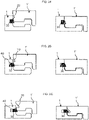
- FIG. 1 A known locking system for building panels, which comprises a displaceable and resilient tongue 30 cooperating with a tongue groove 20 for vertical locking of the short edges is shown in FIG. 1 .
- the tongue 30 is a separate part and is made of, e.g., plastic, and inserted in a displacement groove at a first short edge of a panel.
- the tongue is pushed into a displacement groove during a vertical assembling of the short edges of the panels and springs back into a tongue groove at a second short edge of an adjacent panel when the panels have reached a locked position.
- the long edges of the panels are provided with a locking system, which enables assembling to an adjacent panel by an angling movement, to obtain a simultaneous assembling of adjacent long and short edges.
- FIGS. 2A-B show cross sections of different embodiments of the known displaceable and resilient tongue 30 during assembling of two adjacent short edges.
- the panel with the tongue groove is lowered in relation to the panel with tongue 30, which is pushed into the displacement groove by the lowered panel.
- the tongue springs back, and into the tongue groove, when the panels has reached an assembled position, and locks the panels vertically.
- a known locking system for panels comprising a tongue 30, which is displaceable along the short edge 4a of a panel 1 in a displacement groove 40 and cooperates with a tongue groove 20 for vertical locking of adjacent short edges 4a, 4b is disclosed in FIG. 3 .
- the tongue is a separate part and is provided with several protrusions 31a, which initially match recesses 33b of the tongue groove 20.
- the panels 1, 1' may be assembled by a vertical movement and the tongue is displaced, by applying a force at a part 32 of the tongue 30, to a position in which the protrusions no longer match the recesses in order to obtain the vertical locking.
- the long edges 5a, 5b of the panels are provided with a locking system, which enables assembling to an adjacent panel 1" by an angling movement, to obtain a simultaneous assembling of adjacent long 5a, 5b and short edges 4a, 4b.
- Embodiments of the invention is shown in FIGS. 4 , 5 , 6A-C , 7A-D , 8A-B and 9A-B .
- a locking system is formed at adjacent edges of an adjacent first and second panel 1, 1' for locking the adjacent edges in a vertical and/or horizontal direction.
- An embodiment of the locking system enables assembling of panels at the adjacent edges by a vertical movement, see FIGS. 7A-D .
- the locking system is preferably formed by mechanical cutting, such as milling, drilling and/or sawing, of the edges of the panels.
- a tongue 30 is formed at an edge of the first panel 1.
- the tongue 30 cooperates with a tongue groove 20, which is formed at an edge of an adjacent panel 1', for vertical locking of the panel 1, 1'.
- a locking strip 8 with a vertically protruding locking element is formed in the edge of the first panel.
- the locking element 6 cooperates with a locking groove 14, formed at the edge of the second panel 1', for horizontal locking of the panels 1, 1'.
- a displacement groove 60 is formed in the edge of the first panel behind the tongue 30.
- the displacement groove 60 makes a part 66 of the tongue 30 displaceable.
- the displaceable part 66 is pushed into the displacement groove 60 by a lower lip 31 of the tongue groove 20.
- the displaceable part 66 springs back and into the tongue groove 20.
- FIGS 4 , 5 , 6A-C , 7A-D and 8B show a first embodiment comprising a tongue 30 with two displaceable parts 66 and three fixed parts 68, two displacement grooves 60, and a lower lip 31 of a tongue groove 20 with three recesses 69.
- the cross section in FIG. 6A is at the D-D line indicated in FIG. 8A and the cross section in FIG. 6B is at the C-C line indicated in FIG. 8A .
- FIG. 8A shows a second embodiment comprising a tongue 30 with one displaceable part 66 and two fixed parts 68, one displacement groove 60, and a lower lip of the tongue groove 20 with two recesses 69.
- the first embodiment is shown in a 3D view in FIG. 4 and 5 .
- FIGS. 6A and B and the side view in FIG. 6C show that a lower surface of the displaceable part 66 cooperates, for vertical locking of adjacent edges of the panels 1,1', with a contact surface 70 of the lower lip 31 of the tongue groove 20.
- a vertical movement of the displaceable part is restrained, since the displaceable part of the tongue is continuous with the fixed part 68 of the tongue 30a.
- the displacement groove 60 is formed from the underside of the first panel 1' and comprises an inner wall 61, an outer wall 62, and an upper wall 67.
- the displacement groove 60 may be positioned, in relation to the edge of the first panel, such that the thickness of the outer wall at a first 64 and upper part of the displacement groove 60, at the upper surface 65 of the tongue 30, is configured such that the outer wall breaks during assembling of the building panels when the displaceable part 66 of the tongue is pushed into the displacement groove 60.
- the displacement groove 60 may also be positioned, in relation to the edge of the first panel, such that the thickness of the outer wall of the displacement groove 60 at a second part 63 of the displacement groove 60, below the displaceable part 66 of the tongue 30, is configured such that outer wall breaks during assembling of the building panels when the displaceable part 66 of the tongue is pushed into the displacement groove 60.
- the walls at the at the first 64 and upper part of the displacement groove 60 and/or the second part 63 of the displacement groove 60 may also be broken before assembling of the building panels by pushing the displaceable part 66 of the tongue 30 into the displacement groove by a tool, such as a rotating wheel.
- a tool such as a rotating wheel.
- An alternative is to use a cutting tool, such as a rotating wheel to separate the displaceable part 66 from the walls.
- the broken outer wall of the displacement groove may cooperate with the displaceable part of the tongue and thereby improve the guiding of the displaceable part 66 of the tongue 30 and/or improve the vertical locking.
- the displacement groove 60 is positioned, relation to the edge of the first panel, such that a sidewardly open groove is formed at the first and/or second part 64, 63 of the displacement groove, the force required to push the displaceable part 66 of the tongue 30 into the displacement groove 60 is lowered.
- the contact surface 70 of the lower lip 31 may be positioned such that the displaceable part 66 of the tongue 30 is prevented to spring back to its initial position before assembling and thereby remains, in an assembled and locked position of the panels 1, 1', partly in the displacement groove 66.
- This position of the contact surface 70 result in that the lower surface of the displaceable part of the tongue asserts a force against the contact surface of lower lip in the locked position of the panels 1,1', which is shown in FIGS. 9A and 9B .
- the asserted force improves the locking and a play between the panels may be possibly avoided or reduced.
- the edges of the adjacent panels may be provided with upper overlapping surfaces 90, which are shown in FIG. 9B .
- the upper overlapping surfaces are preferably essentially horizontal.
- the upper wall 67 of the displacement groove 60 may cooperate, for an improved vertical locking of the adjacent edges of the first and second panels 1,1', with an upper surface 65 of the displaceable part 66 of the tongue 30.
- the displacement groove 60 may be filled or provided with an elastic material such as plastic or rubber.
- the improved spring properties may result in an improved locking.
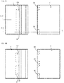
- FIG. 10A An embodiment not part of the present invention comprising a displacement groove 60 with an outer wall, which is not intended to break during assembling, is shown in FIG. 10A .
- the side view in FIG. 10A shows that the distance from the edge of the first panel 1 is increased.
- the displacement groove has the result that a resilient and displaceable tongue part 66 is obtained.
- the top view in FIG. 10B shows an embodiment with an edge of a first panel 1 comprising two displacement grooves 60 and a tongue 30 with two resilient and displaceable parts 66 and three fixed parts 68 and an adjacent edge of a second panel 1' comprising a tongue groove with a lower lip provided with three recesses 69 that matches the fixed parts 68 of the tongue.
- the tongue comprises an upper essentially horizontal surface 90, which preferably extends along the whole edge.
- the upper essentially horizontal surface increases the strength of the locking system.
- FIG. 12A shows in a side view that the size of the tongue may be increased for building panels comprising favourably resilient material.
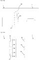
- FIGS. 11A-C show an embodiment not part of the present invention in which also parts of the lower lip of the tongue groove is made flexible and resilient. This is achieved by providing a displacement groove also at the edge of the second panel.
- the side view in FIG. 11A and the cross section in FIG. 11C show an embodiment comprising a displacement groove 71 which downwardly open at a distance from the tongue groove.
- the cross section in FIG.11C is indicated in the top view in FIG.11B by the A-A line.
- the cross section in FIG.11D is indicated in the top view in FIG.11B by the B-B line.
- 11B shows an embodiment with an edge of a first panel 1 comprising two displacement grooves 60 and a tongue with two resilient and displaceable parts 66 and three fixed parts 68 at an edge of a first panel 1, and an adjacent edge of a second panel 1' comprising a tongue groove with a lower lip provided with three recesses 69 that correspond to fixed parts 68 of the tongue, and two displacement grooves 71, to obtain two flexible parts at the lower lip of the tongue groove.
- FIGS. 12B-C Alternative shapes of displacement grooves 60, 71 at the edge of the first and second panel 1, 1' are shown in FIGS. 12B-C .
- the upper wall of the displacement groove is of a rounded shape in order to increase the strength of the displacement groove.
Description
- The present invention relates to a building panel such as a floor panel, a wall panel, a ceiling panel, a furniture component or the like, which is provided with a mechanical locking system, and a method for producing said building panel with said locking system.
- Building panels provided with a mechanical locking system comprising a displaceable and resilient tongue cooperating with a tongue groove for vertical locking is known and disclosed in, e.g.,
WO2006/043893 . The tongue is a separate part and is made of e.g. plastic and inserted in a displacement groove at an edge of a panel. The tongue is pushed into the displacement groove during a vertical assembling of the panels and springs back into the tongue groove of an adjacent panel when the panels have reached a locked position. - Also known is a locking system for panels comprising a tongue, which is displaceable along the edge of a panel, see, e.g.,
WO2009/116926 , and cooperates with a tongue groove for vertical locking. The tongue is a separate part and is provided with several protrusions, which initially match recesses of the tongue groove. The panels may be assembled by a vertical movement and the tongue is displaced to a position in which the protrusions no longer match the recesses in order to obtain the vertical locking. The documentWO 2011/001326 A2 also discloses known building panels having a locking system comprising a displaceable tongue and a displacement groove. - Although the description relates to floor panel, the description of techniques and problems thereof is applicable also for other applications, such as panels for other purposes, for example wall panels, ceiling panels, furniture etc.
- A drawback with the known system is that a separate tongue must be produced and special inserting machines are required to position the tongue in the displacement groove with high precision.
- The above description of various known aspects is the applicant's characterization of such, and is not an admission that any of the above description is considered as prior art.
- It is an object of certain embodiments of the present invention to provide an improvement over the above described techniques and known art.
- A further object is to provide a locking system with a flexible and displaceable tongue that is formed out of the edge of the building panel. Such a system may simplify the production since no loose and additional part is necessary to produce and position at the correct position in the locking system.
- Another object is to provide a more efficient production method and which requires less complicated production equipment.
- At least some of these and other objects and advantages that will be apparent from the description have been achieved by building panels according to
claim 1. - The length of the displacement groove, along the edge of the first panel, is preferably smaller than the length of the edge of the first panel. The length of the displacement groove is preferably in the range of about 10% to about 90% of the length of the edge of the first panel
- The resilient and displaceable part of the tongue makes it possible to assemble the first and the second panel by displacing the edges vertically in relation to each other. A part of the edge of the second panel may push the displaceable part of the tongue into the displacement groove. The resilient and displaceable part of the tongue is preferably configured to be displaced into the displacement groove by a lower lip of the tongue groove during assembling of the first and the second panel. The displaceable part of the tongue may spring at least partly back, when the first and the second panel are positioned in a locked position, and into the tongue groove of the second panel. The part of the edge and the displaceable tongue part are preferably configured such that the displaceable part is pushed in an essentially horizontal direction. An essentially horizontal displacement may decrease the risk that the displaceable part of the tongue gets stuck in the displacement groove.
- The upper wall may cooperate, for guiding the displaceable part of the tongue and/or for the vertical locking, with the upper surface.
- The upper wall may be positioned somewhat above the upper surface of the displaceable part, but a position at an essential equal level, may make the locking system more stable and stronger.
- The displacement groove is arranged in relation to the edge of the first panel so that a sidewardly open groove is created, at the outer wall of the displacement groove, above the displaceable part of the tongue.
- The thickness of the outer wall of the displacement groove at a first and upper part of the displacement groove, at the upper surface of the tongue, is preferably configured such that the outer wall at the first and upper part breaks during said assembling of the building panels when the displaceable part of the tongue is pushed into the displacement groove.
- The thickness of the outer wall of the displacement groove at a second part of the displacement groove, below the displaceable part of the tongue, is preferably configured such that such that the outer wall at second part breaks during said assembling of the building panels when the displaceable part of the tongue is pushed into the displacement groove.
- The displacement groove is sidewardly open at the first and second part of the displacement groove.
- A wall that breaks may provide overlapping surfaces between the displacement groove and the displaceable part when the displaceable part is not pushed into the displacement groove. The overlapping surfaces make the locking system more stable and stronger.
- A sidewardly open displacement groove makes it easier to push the displaceable part of the tongue into the displacement groove.
- The broken outer wall of the displacement groove may cooperate, for guiding the displaceable part of the tongue and/or for the vertical locking, with the displaceable part of the tongue.
- The tongue may comprise a fixed part at each side of the displaceable part of the tongue.
- The tongue groove may comprise recesses, which match the fixed part of the tongue.
- The recesses may be in a lower lip of the tongue groove. The length, along the edge of the second panel, of the lower lip between the recesses is preferably smaller than the length displacement groove.
- A contact surface of the lower lip of the tongue groove may cooperate, for the vertical locking, with a lower surface of the displaceable part of the tongue.
- The contact surface may be positioned such that when the displaceable part of the tongue springs back, during assembling of the building panels, the displaceable part is prevented to reach its original position. The lower surface of the displaceable part tongue may assert a force against the contact surface of lower lip in order to avoid a play between the panels.
- The tongue may have several displaceable parts and the edge of the first panel may be provided with several displacement grooves.
- The locking system may comprise a locking element, preferably arranged on a locking strip, at the edge of the first or the second panel, which cooperates with a locking groove at the edge of the other of the first or the second panel, for locking the panels horizontally.
- The first and the second panel are preferably essential equal, thus an edge opposite said edge of the first panel is provided with the same parts of the locking system as said edge of the second panel.
- The panels may be square-shaped and the edges between the said edge and said opposite edge are preferably provided with a locking system which enables assembling to an adjacent panel by an angling movement.
- The displacement groove may be filled with a resilient material, such as plastic or rubber, to improve the resilient properties of the displaceable part and/or to make the locking system stronger.
- The building panel may be a floor panel, a wall panel, a ceiling panel, a furniture component or the like.
- The core of the building panels may be a wood-based core, preferably made of MDF, HDF, OSB, WPC, or particleboard or of plastic e.g. vinyl or PVC.
- The edge of the panels, of which the locking system may be made, may comprise the core material.
- Another aspect not part of the invention are building panels provided with a mechanical locking system comprising a tongue, at an edge of a first panel, cooperating with a tongue groove, at an edge of an adjacent second panel, for vertical locking of the building panels. The edge of the first panel may be provided with a displacement groove to obtain a resilient and displaceable tongue part. Said displacement groove may be downwardly open, and comprises an inner wall, an outer wall and an upper wall. The tongue may be formed out of the edge of the first panel. The resilient and displaceable part of the tongue may be configured to be displaced partly into the displacement groove by a lower lip of the tongue groove during assembling of the first and the second panel by a vertical displacement of the second panel toward the first panel.
- The thickness of the outer wall of the displacement groove at a first and upper part of the displacement groove, above the upper surface of the tongue, is configured such that the resilient and displaceable tongue part is obtained. Also the thickness of the outer wall of the displacement groove at a second part of the displacement groove, below the resilient and displaceable part of the tongue, is configured such that the resilient and displaceable tongue part is obtained. The outer wall at the first and upper part and at the second part is not, according to certain embodiments of the second aspect, intended to break. The purpose of the displacement groove and the outer wall at the first and upper part and at the second part is to make the resilient and displaceable tongue part more resilient and to provide an improved locking strength.
- The tongue may comprise fixed parts at the side of the resilient and displaceable part of the tongue.
- The tongue groove may comprise recesses, which match the fixed part of the tongue.
- A contact surface of a lower lip of the tongue groove may cooperate, for the vertical locking, with a lower surface of the resilient and displaceable part of the tongue.
- The contact surface may be arranged such that when the displaceable part of the tongue springs back, during the assembling of the building panels, the displaceable part is prevented from reaching its original position.
- The tongue may have several displaceable parts and the edge of the first panel may be provided with several displacement grooves.
- Also parts of the lower lip of the tongue groove may be made flexible and resilient. This may be achieved by providing a displacement groove also at the edge of the second panel.
- The building panel may be a floor panel, a wall panel, a ceiling panel, a furniture component or the like.
- The core of the building panels may be a wood-based core, preferably made of MDF, HDF, OSB, WPC, or particleboard or of plastic e.g. vinyl or PVC.
- The edge of the panels, of which the locking system may be made, may comprise the core material.
- Another aspect not part of the invention is a method to produce a building panel according to the previous aspects. The method may comprise the steps of:
- forming the tongue at the edge of the first panel.
- forming the displacement groove at the underside of the first panel, preferably by milling, sawing and/or drilling.
- milling the tongue groove at the opposite edge of said edge of the first panel.
- forming the recesses in the lower lip of the tongue groove, preferably by milling, sawing and/or drilling.
- The present invention will by way of example be described in more detail with reference to the appended schematic drawings, which shows embodiments of the present invention.
-
FIG. 1 shows a known locking system with a separate and resilient tongue. -
FIGS. 2A-C shows a cross section of a known locking system with a separate and displaceable tongue. -
FIG. 3 shows a known locking system with a separate and displaceable tongue. -
FIG. 4 shows a 3D view of building panels according to an embodiment of the invention. -
FIG. 5 shows a 3D view of building panels according to an embodiment of the invention. -
FIGS. 6A-B show cross sections of building panels according to an embodiment of the invention. -
FIG. 6C shows a side view of building panels according to an embodiment of the invention. -
FIGS. 7A-D shows an embodiment of assembling according to an embodiment of the invention. -
FIGS. 8A-B show top views of the building panels according to embodiments of the invention. -
FIGS. 9A-B show a cross of the building panels according to embodiments of the invention. -
FIGS. 10A-B show a top view and a side view of the building panels according to an embodiment not part of the invention. -
FIGS. 11A-D show a top view, a side view and two cross sections of building panels according to an embodiment not part of the invention. -
FIGS. 12A-C show a side view and two cross-sections of building panels according to an embodiment not part of the invention. - A known locking system for building panels, which comprises a displaceable and
resilient tongue 30 cooperating with atongue groove 20 for vertical locking of the short edges is shown inFIG. 1 . Thetongue 30 is a separate part and is made of, e.g., plastic, and inserted in a displacement groove at a first short edge of a panel. The tongue is pushed into a displacement groove during a vertical assembling of the short edges of the panels and springs back into a tongue groove at a second short edge of an adjacent panel when the panels have reached a locked position. The long edges of the panels are provided with a locking system, which enables assembling to an adjacent panel by an angling movement, to obtain a simultaneous assembling of adjacent long and short edges. -
FIGS. 2A-B show cross sections of different embodiments of the known displaceable andresilient tongue 30 during assembling of two adjacent short edges. The panel with the tongue groove is lowered in relation to the panel withtongue 30, which is pushed into the displacement groove by the lowered panel. The tongue springs back, and into the tongue groove, when the panels has reached an assembled position, and locks the panels vertically. - A known locking system for panels comprising a
tongue 30, which is displaceable along theshort edge 4a of apanel 1 in adisplacement groove 40 and cooperates with atongue groove 20 for vertical locking of adjacentshort edges FIG. 3 . The tongue is a separate part and is provided withseveral protrusions 31a, which initially matchrecesses 33b of thetongue groove 20. Thepanels 1, 1' may be assembled by a vertical movement and the tongue is displaced, by applying a force at apart 32 of thetongue 30, to a position in which the protrusions no longer match the recesses in order to obtain the vertical locking. Thelong edges adjacent panel 1" by an angling movement, to obtain a simultaneous assembling of adjacent long 5a, 5b andshort edges - Embodiments of the invention is shown in
FIGS. 4 ,5 ,6A-C ,7A-D ,8A-B and9A-B . A locking system is formed at adjacent edges of an adjacent first andsecond panel 1, 1' for locking the adjacent edges in a vertical and/or horizontal direction. An embodiment of the locking system enables assembling of panels at the adjacent edges by a vertical movement, seeFIGS. 7A-D . The locking system is preferably formed by mechanical cutting, such as milling, drilling and/or sawing, of the edges of the panels. - A
tongue 30 is formed at an edge of thefirst panel 1. Thetongue 30 cooperates with atongue groove 20, which is formed at an edge of an adjacent panel 1', for vertical locking of thepanel 1, 1'. A lockingstrip 8 with a vertically protruding locking element is formed in the edge of the first panel. The lockingelement 6 cooperates with a lockinggroove 14, formed at the edge of the second panel 1', for horizontal locking of thepanels 1, 1'. - A
displacement groove 60 is formed in the edge of the first panel behind thetongue 30. Thedisplacement groove 60 makes apart 66 of thetongue 30 displaceable. During assembling of the first and thesecond panel 1, 1' thedisplaceable part 66 is pushed into thedisplacement groove 60 by alower lip 31 of thetongue groove 20. When the panels are in a locked position thedisplaceable part 66 springs back and into thetongue groove 20. -
Other parts 68 of thetongue 30, beside thedisplacement groove 60 and thedisplaceable part 66 of thetongue 30, is fixed. To enable thepanels 1, 1' to be assembled by a vertical movement, recesses 69 are formed in alower lip 31 of thetongue groove 20. Therecesses 69 match the fixedparts 68 of the tongue. -
FIGS 4 ,5 ,6A-C ,7A-D and8B show a first embodiment comprising atongue 30 with twodisplaceable parts 66 and three fixedparts 68, twodisplacement grooves 60, and alower lip 31 of atongue groove 20 with threerecesses 69. The cross section inFIG. 6A is at the D-D line indicated inFIG. 8A and the cross section inFIG. 6B is at the C-C line indicated inFIG. 8A . -
FIG. 8A shows a second embodiment comprising atongue 30 with onedisplaceable part 66 and two fixedparts 68, onedisplacement groove 60, and a lower lip of thetongue groove 20 with tworecesses 69. - The first embodiment is shown in a 3D view in
FIG. 4 and5 . - The cross sections in
FIGS. 6A and B and the side view inFIG. 6C , show that a lower surface of thedisplaceable part 66 cooperates, for vertical locking of adjacent edges of thepanels 1,1', with acontact surface 70 of thelower lip 31 of thetongue groove 20. A vertical movement of the displaceable part is restrained, since the displaceable part of the tongue is continuous with the fixedpart 68 of the tongue 30a. - The
displacement groove 60 is formed from the underside of the first panel 1' and comprises aninner wall 61, anouter wall 62, and anupper wall 67. Thedisplacement groove 60 may be positioned, in relation to the edge of the first panel, such that the thickness of the outer wall at a first 64 and upper part of thedisplacement groove 60, at theupper surface 65 of thetongue 30, is configured such that the outer wall breaks during assembling of the building panels when thedisplaceable part 66 of the tongue is pushed into thedisplacement groove 60. - The
displacement groove 60 may also be positioned, in relation to the edge of the first panel, such that the thickness of the outer wall of thedisplacement groove 60 at asecond part 63 of thedisplacement groove 60, below thedisplaceable part 66 of thetongue 30, is configured such that outer wall breaks during assembling of the building panels when thedisplaceable part 66 of the tongue is pushed into thedisplacement groove 60. - The walls at the at the first 64 and upper part of the
displacement groove 60 and/or thesecond part 63 of thedisplacement groove 60 may also be broken before assembling of the building panels by pushing thedisplaceable part 66 of thetongue 30 into the displacement groove by a tool, such as a rotating wheel. An alternative is to use a cutting tool, such as a rotating wheel to separate thedisplaceable part 66 from the walls. - The broken outer wall of the displacement groove may cooperate with the displaceable part of the tongue and thereby improve the guiding of the
displaceable part 66 of thetongue 30 and/or improve the vertical locking. - If the
displacement groove 60 is positioned, relation to the edge of the first panel, such that a sidewardly open groove is formed at the first and/orsecond part displaceable part 66 of thetongue 30 into thedisplacement groove 60 is lowered. - The
contact surface 70 of thelower lip 31 may be positioned such that thedisplaceable part 66 of thetongue 30 is prevented to spring back to its initial position before assembling and thereby remains, in an assembled and locked position of thepanels 1, 1', partly in thedisplacement groove 66. This position of thecontact surface 70 result in that the lower surface of the displaceable part of the tongue asserts a force against the contact surface of lower lip in the locked position of thepanels 1,1', which is shown inFIGS. 9A and 9B . The asserted force improves the locking and a play between the panels may be possibly avoided or reduced. - To decrease the force applied on the tongue when a load is applied on the building panels and to further improve the strength and tolerances of the locking system, the edges of the adjacent panels may be provided with upper overlapping surfaces 90, which are shown in
FIG. 9B . The upper overlapping surfaces are preferably essentially horizontal. - If the tongue remains in the
displacement groove 60 theupper wall 67 of thedisplacement groove 60 may cooperate, for an improved vertical locking of the adjacent edges of the first andsecond panels 1,1', with anupper surface 65 of thedisplaceable part 66 of thetongue 30. - In order to improve the spring properties of the
displaceable part 66 of thetongue 30, thedisplacement groove 60 may be filled or provided with an elastic material such as plastic or rubber. The improved spring properties may result in an improved locking. - An embodiment not part of the present invention comprising a
displacement groove 60 with an outer wall, which is not intended to break during assembling, is shown inFIG. 10A . The side view inFIG. 10A shows that the distance from the edge of thefirst panel 1 is increased. The displacement groove has the result that a resilient anddisplaceable tongue part 66 is obtained. The top view inFIG. 10B shows an embodiment with an edge of afirst panel 1 comprising twodisplacement grooves 60 and atongue 30 with two resilient anddisplaceable parts 66 and three fixedparts 68 and an adjacent edge of a second panel 1' comprising a tongue groove with a lower lip provided with threerecesses 69 that matches the fixedparts 68 of the tongue. The tongue comprises an upper essentiallyhorizontal surface 90, which preferably extends along the whole edge. The upper essentially horizontal surface increases the strength of the locking system.FIG. 12A shows in a side view that the size of the tongue may be increased for building panels comprising favourably resilient material. -
FIGS. 11A-C show an embodiment not part of the present invention in which also parts of the lower lip of the tongue groove is made flexible and resilient. This is achieved by providing a displacement groove also at the edge of the second panel. The side view inFIG. 11A and the cross section inFIG. 11C show an embodiment comprising adisplacement groove 71 which downwardly open at a distance from the tongue groove. The cross section inFIG.11C is indicated in the top view inFIG.11B by the A-A line. The cross section inFIG.11D is indicated in the top view inFIG.11B by the B-B line. The top view inFIG. 11B shows an embodiment with an edge of afirst panel 1 comprising twodisplacement grooves 60 and a tongue with two resilient anddisplaceable parts 66 and three fixedparts 68 at an edge of afirst panel 1, and an adjacent edge of a second panel 1' comprising a tongue groove with a lower lip provided with threerecesses 69 that correspond to fixedparts 68 of the tongue, and twodisplacement grooves 71, to obtain two flexible parts at the lower lip of the tongue groove. - Alternative shapes of
displacement grooves second panel 1, 1' are shown inFIGS. 12B-C . The upper wall of the displacement groove is of a rounded shape in order to increase the strength of the displacement groove.
Claims (12)
- Building panels (1, 1') provided with a mechanical locking system comprising a tongue (30), at an edge of a first panel (1), cooperating with a tongue groove (20), at an edge of an adjacent second panel (1'), for vertical locking of the building panels, whereinthe edge of the first panel is provided with a displacement groove (60) to obtain a resilient a displaceable tongue part (66), said displacement groove is downwardly open, and comprises an inner wall (61), an outer wall (62) and an upper wall (67),the tongue (30) is formed out of the edge of the first panel,the resilient and displaceable part (66) of the tongue (30) is configured to be displaced into the displacement groove (60) by a lower lip of the tongue groove during assembling of the first and the second panel (1, 1') by a vertical displacement of the second panel toward the first panel,the displacement groove (60) is formed from the underside of the first panel (1),the displacement groove (60) is arranged in relation to the edge of thefirst panel so that a sidewardly open groove is created, at the outer wall (62) of the displacement groove, above the displaceable part of the tongue (30),the outer wall (62) of the displacement groove (60) at a first and upper part (64) of the displacement groove (60), at an upper surface (65) of the tongue (30), is sidewardly open, andthe outer wall (62) of the displacement groove (60) at a second part (63) of the displacement groove (60), below the resilient and displaceable part (66) of the tongue (30), is sidewardly open, characterized in thatthe displacement groove (60) extends horizontally to a vertical plane defined in a locked position by upper and outermost edges of the first (1) and second (1') building panels.
- Building panels as claimed in claim 1, wherein the upper wall (67) is vertically positioned at the upper surface (65) of the resilient and displaceable part (66) of the tongue (30).
- Building panels as claimed in claim 2, wherein the upper wall (67) is configured to guide the resilient and displaceable part (66) of the tongue (30).
- Building panels as claimed in claim 2 or 3, wherein the upper wall (67) is configured to cooperate with the upper surface (65) of the resilient and displaceable part (66) for the vertical locking.
- Building panels as claimed in any one of the preceding claims, wherein the tongue (30) comprises fixed parts (68) at the side of the resilient and displaceable part (66) of the tongue (30).
- Building panels as claimed in claim 5, wherein the tongue groove (20) comprises recesses, which correspond to the fixed part (68) of the tongue (30).
- Building panels as claimed in any one of the preceding claims, wherein a contact surface (70) of a lower lip (31) of the tongue groove (20) cooperates, for the vertical locking, with a lower surface of the displaceable part (66) of the tongue (30).
- Building panels as claimed in claim 7, wherein the contact surface (70) is arranged such that when the resilient and displaceable part (66) of the tongue springs back, during the assembling of the building panels, the displaceable part (66) is prevented from reaching its original position.
- Building panels as claimed in any one of the preceding claims, wherein the tongue (30) has several displaceable parts (66) and that the edge of the first panel is provided with several displacement grooves (60).
- Building panels as claimed in any one of the claims 1-9, wherein the building panels are floor panels, wall panels, ceiling panels, or furniture components.
- Building panels as claimed in any one of the claims 1-10, wherein building panels comprise a core which is wood-based, such as MDF, HDF, OSB, WPC, or particleboard or of plastic, such as vinyl or PVC.
- Building panels as claimed in any one of the claims 1-11, wherein the locking system is made in an edge of the building panels which comprise the core material.
Applications Claiming Priority (5)
| Application Number | Priority Date | Filing Date | Title |
|---|---|---|---|
| US201261620233P | 2012-04-04 | 2012-04-04 | |
| SE1250346 | 2012-04-04 | ||
| PCT/SE2013/050367 WO2013151494A1 (en) | 2012-04-04 | 2013-04-03 | Building panel with a mechanical locking system |
| EP13772407.6A EP2852722B1 (en) | 2012-04-04 | 2013-04-03 | Building panel with a mechanical locking system |
| EP17171768.9A EP3235971B1 (en) | 2012-04-04 | 2013-04-03 | Building panel with a mechanical locking system |
Related Parent Applications (2)
| Application Number | Title | Priority Date | Filing Date |
|---|---|---|---|
| EP13772407.6A Division EP2852722B1 (en) | 2012-04-04 | 2013-04-03 | Building panel with a mechanical locking system |
| EP17171768.9A Division EP3235971B1 (en) | 2012-04-04 | 2013-04-03 | Building panel with a mechanical locking system |
Publications (2)
| Publication Number | Publication Date |
|---|---|
| EP3460143A1 EP3460143A1 (en) | 2019-03-27 |
| EP3460143B1 true EP3460143B1 (en) | 2022-09-28 |
Family
ID=49300845
Family Applications (3)
| Application Number | Title | Priority Date | Filing Date |
|---|---|---|---|
| EP17171768.9A Active EP3235971B1 (en) | 2012-04-04 | 2013-04-03 | Building panel with a mechanical locking system |
| EP13772407.6A Active EP2852722B1 (en) | 2012-04-04 | 2013-04-03 | Building panel with a mechanical locking system |
| EP18205688.7A Active EP3460143B1 (en) | 2012-04-04 | 2013-04-03 | Building panel with a mechanical locking system |
Family Applications Before (2)
| Application Number | Title | Priority Date | Filing Date |
|---|---|---|---|
| EP17171768.9A Active EP3235971B1 (en) | 2012-04-04 | 2013-04-03 | Building panel with a mechanical locking system |
| EP13772407.6A Active EP2852722B1 (en) | 2012-04-04 | 2013-04-03 | Building panel with a mechanical locking system |
Country Status (10)
| Country | Link |
|---|---|
| EP (3) | EP3235971B1 (en) |
| KR (1) | KR102149414B1 (en) |
| CN (1) | CN104204379B (en) |
| CA (1) | CA2867324C (en) |
| ES (1) | ES2639512T3 (en) |
| LT (1) | LT2852722T (en) |
| PL (2) | PL2852722T3 (en) |
| PT (1) | PT2852722T (en) |
| RU (1) | RU2622945C2 (en) |
| WO (1) | WO2013151494A1 (en) |
Families Citing this family (9)
| Publication number | Priority date | Publication date | Assignee | Title |
|---|---|---|---|---|
| US9216541B2 (en) | 2012-04-04 | 2015-12-22 | Valinge Innovation Ab | Method for producing a mechanical locking system for building panels |
| DE102013100345B4 (en) * | 2013-01-14 | 2023-07-06 | Guido Schulte | Covering made of mechanically connectable elements |
| CN104481026A (en) * | 2014-11-05 | 2015-04-01 | 安徽鸿路钢结构(集团)股份有限公司 | Easily-dismounted steel-frame structure of makeshift house |
| BR112017012681B1 (en) | 2014-12-22 | 2022-05-03 | Ceraloc Innovation Ab | Set of essentially identical floor panels |
| EP3247844B1 (en) * | 2015-01-16 | 2022-03-16 | Ceraloc Innovation AB | Mechanical locking system for floor panels |
| BE1026099B1 (en) * | 2018-03-16 | 2019-10-14 | Kreafin Group Sa | PANEL OF WHICH THE COUPLING DEVICES ARE SUITABLE FOR CONNECTING THE LONG SIDE AND / OR KOPSE SIDE TOGETHER |
| EP3798385A1 (en) * | 2019-09-24 | 2021-03-31 | Välinge Innovation AB | Building panel |
| CA3153635A1 (en) * | 2019-09-25 | 2021-04-01 | Valinge Innovation Ab | Panel with locking device |
| WO2021246945A1 (en) * | 2020-06-05 | 2021-12-09 | Välinge Innovation AB | Building panels comprising a locking device |
Citations (1)
| Publication number | Priority date | Publication date | Assignee | Title |
|---|---|---|---|---|
| WO2004003314A1 (en) * | 2002-06-28 | 2004-01-08 | Fritz Egger Gmbh / Co. | Panel of a floor system, particularly a laminate floor |
Family Cites Families (15)
| Publication number | Priority date | Publication date | Assignee | Title |
|---|---|---|---|---|
| DE20001788U1 (en) * | 2000-02-02 | 2000-06-29 | Kronospan Tech Co Ltd | Panel with plug profile |
| EP1350904B2 (en) * | 2002-04-05 | 2012-10-24 | tilo GmbH | Floor planks |
| SI1650375T2 (en) | 2004-10-22 | 2011-04-29 | Vaelinge Innovation Ab | A set of floor panels |
| DE202007018662U1 (en) * | 2007-03-26 | 2009-02-19 | Kronotec Ag | Panel, in particular floor panel |
| DE102007017087B4 (en) * | 2007-04-10 | 2009-06-25 | Kronotec Ag | Panel, in particular floor panel |
| BE1018600A5 (en) * | 2007-11-23 | 2011-04-05 | Flooring Ind Ltd Sarl | FLOOR PANEL. |
| EP3910131A3 (en) | 2008-01-31 | 2022-03-30 | Välinge Innovation AB | Mechanical locking of floor panels |
| DE202008012001U1 (en) * | 2008-09-09 | 2008-11-27 | Akzenta Paneele + Profile Gmbh | Floor panel with a plastic carrier layer |
| BE1018627A5 (en) * | 2009-01-16 | 2011-05-03 | Flooring Ind Ltd Sarl | FLOOR PANEL. |
| EP2226447B1 (en) * | 2009-02-27 | 2012-06-06 | Flooring Technologies Ltd. | Panelling, in particular floor panelling |
| DE102009035275A1 (en) * | 2009-06-08 | 2010-12-09 | Fritz Egger Gmbh & Co. | Panel of a floor system |
| BE1018802A3 (en) * | 2009-06-29 | 2011-09-06 | Flooring Ind Ltd Sarl | PANEL, MORE SPECIAL FLOOR PANEL. |
| DE102009048050B3 (en) * | 2009-10-02 | 2011-01-20 | Guido Schulte | Surface made of mechanical interconnectable elements |
| EP2524093B1 (en) * | 2010-01-12 | 2020-02-05 | Välinge Innovation AB | Mechanical locking system for floor panels |
| CA3028847A1 (en) * | 2010-04-15 | 2011-10-20 | Unilin, Bvba | Floor panel assembly |
-
2013
- 2013-04-03 CN CN201380016242.3A patent/CN104204379B/en active Active
- 2013-04-03 PL PL13772407T patent/PL2852722T3/en unknown
- 2013-04-03 LT LTEP13772407.6T patent/LT2852722T/en unknown
- 2013-04-03 ES ES13772407.6T patent/ES2639512T3/en active Active
- 2013-04-03 RU RU2014142450A patent/RU2622945C2/en active
- 2013-04-03 WO PCT/SE2013/050367 patent/WO2013151494A1/en active Application Filing
- 2013-04-03 KR KR1020147029519A patent/KR102149414B1/en active IP Right Grant
- 2013-04-03 EP EP17171768.9A patent/EP3235971B1/en active Active
- 2013-04-03 EP EP13772407.6A patent/EP2852722B1/en active Active
- 2013-04-03 PL PL17171768T patent/PL3235971T3/en unknown
- 2013-04-03 CA CA2867324A patent/CA2867324C/en active Active
- 2013-04-03 EP EP18205688.7A patent/EP3460143B1/en active Active
- 2013-04-03 PT PT137724076T patent/PT2852722T/en unknown
Patent Citations (1)
| Publication number | Priority date | Publication date | Assignee | Title |
|---|---|---|---|---|
| WO2004003314A1 (en) * | 2002-06-28 | 2004-01-08 | Fritz Egger Gmbh / Co. | Panel of a floor system, particularly a laminate floor |
Also Published As
| Publication number | Publication date |
|---|---|
| KR102149414B1 (en) | 2020-08-28 |
| EP2852722B1 (en) | 2017-06-07 |
| EP3460143A1 (en) | 2019-03-27 |
| EP3235971B1 (en) | 2018-11-14 |
| EP2852722A4 (en) | 2016-06-15 |
| CA2867324C (en) | 2020-02-25 |
| PL2852722T3 (en) | 2017-10-31 |
| WO2013151494A1 (en) | 2013-10-10 |
| PT2852722T (en) | 2017-08-25 |
| RU2622945C2 (en) | 2017-06-21 |
| KR20140144710A (en) | 2014-12-19 |
| CA2867324A1 (en) | 2013-10-10 |
| EP3235971A1 (en) | 2017-10-25 |
| PL3235971T3 (en) | 2019-03-29 |
| LT2852722T (en) | 2017-08-10 |
| CN104204379A (en) | 2014-12-10 |
| EP2852722A1 (en) | 2015-04-01 |
| ES2639512T3 (en) | 2017-10-26 |
| CN104204379B (en) | 2016-10-19 |
| RU2014142450A (en) | 2016-05-27 |
Similar Documents
| Publication | Publication Date | Title |
|---|---|---|
| US10480196B2 (en) | Building panel with a mechanical locking system | |
| EP3460143B1 (en) | Building panel with a mechanical locking system | |
| US10794065B2 (en) | Method for producing a mechanical locking system for building panels | |
| US9945130B2 (en) | Building panels provided with a mechanical locking system | |
| US9723923B2 (en) | Panel with a slider | |
| EP2855795B1 (en) | Method for producing a mechanical locking system for building panels | |
| EP2964851B1 (en) | Building panels provided with a mechanical locking system |
Legal Events
| Date | Code | Title | Description |
|---|---|---|---|
| PUAI | Public reference made under article 153(3) epc to a published international application that has entered the european phase |
Free format text: ORIGINAL CODE: 0009012 |
|
| STAA | Information on the status of an ep patent application or granted ep patent |
Free format text: STATUS: REQUEST FOR EXAMINATION WAS MADE |
|
| 17P | Request for examination filed |
Effective date: 20181112 |
|
| AC | Divisional application: reference to earlier application |
Ref document number: 2852722 Country of ref document: EP Kind code of ref document: P Ref document number: 3235971 Country of ref document: EP Kind code of ref document: P |
|
| AK | Designated contracting states |
Kind code of ref document: A1 Designated state(s): AL AT BE BG CH CY CZ DE DK EE ES FI FR GB GR HR HU IE IS IT LI LT LU LV MC MK MT NL NO PL PT RO RS SE SI SK SM TR |
|
| STAA | Information on the status of an ep patent application or granted ep patent |
Free format text: STATUS: EXAMINATION IS IN PROGRESS |
|
| 17Q | First examination report despatched |
Effective date: 20200220 |
|
| STAA | Information on the status of an ep patent application or granted ep patent |
Free format text: STATUS: EXAMINATION IS IN PROGRESS |
|
| STAA | Information on the status of an ep patent application or granted ep patent |
Free format text: STATUS: EXAMINATION IS IN PROGRESS |
|
| RAP3 | Party data changed (applicant data changed or rights of an application transferred) |
Owner name: VAELINGE INNOVATION AB |
|
| GRAP | Despatch of communication of intention to grant a patent |
Free format text: ORIGINAL CODE: EPIDOSNIGR1 |
|
| STAA | Information on the status of an ep patent application or granted ep patent |
Free format text: STATUS: GRANT OF PATENT IS INTENDED |
|
| INTG | Intention to grant announced |
Effective date: 20220214 |
|
| RIN1 | Information on inventor provided before grant (corrected) |
Inventor name: BOO, CHRISTIAN |
|
| GRAS | Grant fee paid |
Free format text: ORIGINAL CODE: EPIDOSNIGR3 |
|
| GRAA | (expected) grant |
Free format text: ORIGINAL CODE: 0009210 |
|
| STAA | Information on the status of an ep patent application or granted ep patent |
Free format text: STATUS: THE PATENT HAS BEEN GRANTED |
|
| AC | Divisional application: reference to earlier application |
Ref document number: 2852722 Country of ref document: EP Kind code of ref document: P Ref document number: 3235971 Country of ref document: EP Kind code of ref document: P |
|
| AK | Designated contracting states |
Kind code of ref document: B1 Designated state(s): AL AT BE BG CH CY CZ DE DK EE ES FI FR GB GR HR HU IE IS IT LI LT LU LV MC MK MT NL NO PL PT RO RS SE SI SK SM TR |
|
| REG | Reference to a national code |
Ref country code: GB Ref legal event code: FG4D |
|
| REG | Reference to a national code |
Ref country code: CH Ref legal event code: EP |
|
| REG | Reference to a national code |
Ref country code: DE Ref legal event code: R096 Ref document number: 602013082610 Country of ref document: DE |
|
| REG | Reference to a national code |
Ref country code: AT Ref legal event code: REF Ref document number: 1521327 Country of ref document: AT Kind code of ref document: T Effective date: 20221015 |
|
| REG | Reference to a national code |
Ref country code: IE Ref legal event code: FG4D |
|
| REG | Reference to a national code |
Ref country code: LT Ref legal event code: MG9D |
|
| PG25 | Lapsed in a contracting state [announced via postgrant information from national office to epo] |
Ref country code: SE Free format text: LAPSE BECAUSE OF FAILURE TO SUBMIT A TRANSLATION OF THE DESCRIPTION OR TO PAY THE FEE WITHIN THE PRESCRIBED TIME-LIMIT Effective date: 20220928 Ref country code: RS Free format text: LAPSE BECAUSE OF FAILURE TO SUBMIT A TRANSLATION OF THE DESCRIPTION OR TO PAY THE FEE WITHIN THE PRESCRIBED TIME-LIMIT Effective date: 20220928 Ref country code: NO Free format text: LAPSE BECAUSE OF FAILURE TO SUBMIT A TRANSLATION OF THE DESCRIPTION OR TO PAY THE FEE WITHIN THE PRESCRIBED TIME-LIMIT Effective date: 20221228 Ref country code: LV Free format text: LAPSE BECAUSE OF FAILURE TO SUBMIT A TRANSLATION OF THE DESCRIPTION OR TO PAY THE FEE WITHIN THE PRESCRIBED TIME-LIMIT Effective date: 20220928 Ref country code: LT Free format text: LAPSE BECAUSE OF FAILURE TO SUBMIT A TRANSLATION OF THE DESCRIPTION OR TO PAY THE FEE WITHIN THE PRESCRIBED TIME-LIMIT Effective date: 20220928 Ref country code: FI Free format text: LAPSE BECAUSE OF FAILURE TO SUBMIT A TRANSLATION OF THE DESCRIPTION OR TO PAY THE FEE WITHIN THE PRESCRIBED TIME-LIMIT Effective date: 20220928 |
|
| REG | Reference to a national code |
Ref country code: NL Ref legal event code: MP Effective date: 20220928 |
|
| REG | Reference to a national code |
Ref country code: AT Ref legal event code: MK05 Ref document number: 1521327 Country of ref document: AT Kind code of ref document: T Effective date: 20220928 |
|
| PG25 | Lapsed in a contracting state [announced via postgrant information from national office to epo] |
Ref country code: HR Free format text: LAPSE BECAUSE OF FAILURE TO SUBMIT A TRANSLATION OF THE DESCRIPTION OR TO PAY THE FEE WITHIN THE PRESCRIBED TIME-LIMIT Effective date: 20220928 Ref country code: GR Free format text: LAPSE BECAUSE OF FAILURE TO SUBMIT A TRANSLATION OF THE DESCRIPTION OR TO PAY THE FEE WITHIN THE PRESCRIBED TIME-LIMIT Effective date: 20221229 |
|
| PG25 | Lapsed in a contracting state [announced via postgrant information from national office to epo] |
Ref country code: SM Free format text: LAPSE BECAUSE OF FAILURE TO SUBMIT A TRANSLATION OF THE DESCRIPTION OR TO PAY THE FEE WITHIN THE PRESCRIBED TIME-LIMIT Effective date: 20220928 Ref country code: RO Free format text: LAPSE BECAUSE OF FAILURE TO SUBMIT A TRANSLATION OF THE DESCRIPTION OR TO PAY THE FEE WITHIN THE PRESCRIBED TIME-LIMIT Effective date: 20220928 Ref country code: PT Free format text: LAPSE BECAUSE OF FAILURE TO SUBMIT A TRANSLATION OF THE DESCRIPTION OR TO PAY THE FEE WITHIN THE PRESCRIBED TIME-LIMIT Effective date: 20230130 Ref country code: ES Free format text: LAPSE BECAUSE OF FAILURE TO SUBMIT A TRANSLATION OF THE DESCRIPTION OR TO PAY THE FEE WITHIN THE PRESCRIBED TIME-LIMIT Effective date: 20220928 Ref country code: CZ Free format text: LAPSE BECAUSE OF FAILURE TO SUBMIT A TRANSLATION OF THE DESCRIPTION OR TO PAY THE FEE WITHIN THE PRESCRIBED TIME-LIMIT Effective date: 20220928 Ref country code: AT Free format text: LAPSE BECAUSE OF FAILURE TO SUBMIT A TRANSLATION OF THE DESCRIPTION OR TO PAY THE FEE WITHIN THE PRESCRIBED TIME-LIMIT Effective date: 20220928 |
|
| PGFP | Annual fee paid to national office [announced via postgrant information from national office to epo] |
Ref country code: FR Payment date: 20230321 Year of fee payment: 11 |
|
| PG25 | Lapsed in a contracting state [announced via postgrant information from national office to epo] |
Ref country code: SK Free format text: LAPSE BECAUSE OF FAILURE TO SUBMIT A TRANSLATION OF THE DESCRIPTION OR TO PAY THE FEE WITHIN THE PRESCRIBED TIME-LIMIT Effective date: 20220928 Ref country code: PL Free format text: LAPSE BECAUSE OF FAILURE TO SUBMIT A TRANSLATION OF THE DESCRIPTION OR TO PAY THE FEE WITHIN THE PRESCRIBED TIME-LIMIT Effective date: 20220928 Ref country code: IS Free format text: LAPSE BECAUSE OF FAILURE TO SUBMIT A TRANSLATION OF THE DESCRIPTION OR TO PAY THE FEE WITHIN THE PRESCRIBED TIME-LIMIT Effective date: 20230128 Ref country code: EE Free format text: LAPSE BECAUSE OF FAILURE TO SUBMIT A TRANSLATION OF THE DESCRIPTION OR TO PAY THE FEE WITHIN THE PRESCRIBED TIME-LIMIT Effective date: 20220928 |
|
| PGFP | Annual fee paid to national office [announced via postgrant information from national office to epo] |
Ref country code: BE Payment date: 20230321 Year of fee payment: 11 |
|
| P01 | Opt-out of the competence of the unified patent court (upc) registered |
Effective date: 20230522 |
|
| REG | Reference to a national code |
Ref country code: DE Ref legal event code: R097 Ref document number: 602013082610 Country of ref document: DE |
|
| PG25 | Lapsed in a contracting state [announced via postgrant information from national office to epo] |
Ref country code: NL Free format text: LAPSE BECAUSE OF FAILURE TO SUBMIT A TRANSLATION OF THE DESCRIPTION OR TO PAY THE FEE WITHIN THE PRESCRIBED TIME-LIMIT Effective date: 20220928 Ref country code: AL Free format text: LAPSE BECAUSE OF FAILURE TO SUBMIT A TRANSLATION OF THE DESCRIPTION OR TO PAY THE FEE WITHIN THE PRESCRIBED TIME-LIMIT Effective date: 20220928 |
|
| PG25 | Lapsed in a contracting state [announced via postgrant information from national office to epo] |
Ref country code: DK Free format text: LAPSE BECAUSE OF FAILURE TO SUBMIT A TRANSLATION OF THE DESCRIPTION OR TO PAY THE FEE WITHIN THE PRESCRIBED TIME-LIMIT Effective date: 20220928 |
|
| PGFP | Annual fee paid to national office [announced via postgrant information from national office to epo] |
Ref country code: DE Payment date: 20230321 Year of fee payment: 11 |
|
| PLBE | No opposition filed within time limit |
Free format text: ORIGINAL CODE: 0009261 |
|
| STAA | Information on the status of an ep patent application or granted ep patent |
Free format text: STATUS: NO OPPOSITION FILED WITHIN TIME LIMIT |
|
| 26N | No opposition filed |
Effective date: 20230629 |
|
| PG25 | Lapsed in a contracting state [announced via postgrant information from national office to epo] |
Ref country code: SI Free format text: LAPSE BECAUSE OF FAILURE TO SUBMIT A TRANSLATION OF THE DESCRIPTION OR TO PAY THE FEE WITHIN THE PRESCRIBED TIME-LIMIT Effective date: 20220928 |
|
| REG | Reference to a national code |
Ref country code: CH Ref legal event code: PL |
|
| GBPC | Gb: european patent ceased through non-payment of renewal fee |
Effective date: 20230403 |
|
| PG25 | Lapsed in a contracting state [announced via postgrant information from national office to epo] |
Ref country code: LU Free format text: LAPSE BECAUSE OF NON-PAYMENT OF DUE FEES Effective date: 20230403 |
|
| PG25 | Lapsed in a contracting state [announced via postgrant information from national office to epo] |
Ref country code: MC Free format text: LAPSE BECAUSE OF FAILURE TO SUBMIT A TRANSLATION OF THE DESCRIPTION OR TO PAY THE FEE WITHIN THE PRESCRIBED TIME-LIMIT Effective date: 20220928 |
|
| PG25 | Lapsed in a contracting state [announced via postgrant information from national office to epo] |
Ref country code: GB Free format text: LAPSE BECAUSE OF NON-PAYMENT OF DUE FEES Effective date: 20230403 |
|
| PG25 | Lapsed in a contracting state [announced via postgrant information from national office to epo] |
Ref country code: MC Free format text: LAPSE BECAUSE OF FAILURE TO SUBMIT A TRANSLATION OF THE DESCRIPTION OR TO PAY THE FEE WITHIN THE PRESCRIBED TIME-LIMIT Effective date: 20220928 Ref country code: LI Free format text: LAPSE BECAUSE OF NON-PAYMENT OF DUE FEES Effective date: 20230430 Ref country code: GB Free format text: LAPSE BECAUSE OF NON-PAYMENT OF DUE FEES Effective date: 20230403 Ref country code: CH Free format text: LAPSE BECAUSE OF NON-PAYMENT OF DUE FEES Effective date: 20230430 |
|
| REG | Reference to a national code |
Ref country code: IE Ref legal event code: MM4A |