EP3889328A1 - Draw texturing machine - Google Patents
Draw texturing machine Download PDFInfo
- Publication number
- EP3889328A1 EP3889328A1 EP21170124.8A EP21170124A EP3889328A1 EP 3889328 A1 EP3889328 A1 EP 3889328A1 EP 21170124 A EP21170124 A EP 21170124A EP 3889328 A1 EP3889328 A1 EP 3889328A1
- Authority
- EP
- European Patent Office
- Prior art keywords
- yarn
- false
- twisting
- axial
- circular plate
- Prior art date
- Legal status (The legal status is an assumption and is not a legal conclusion. Google has not performed a legal analysis and makes no representation as to the accuracy of the status listed.)
- Granted
Links
Images






Classifications
-
- D—TEXTILES; PAPER
- D02—YARNS; MECHANICAL FINISHING OF YARNS OR ROPES; WARPING OR BEAMING
- D02G—CRIMPING OR CURLING FIBRES, FILAMENTS, THREADS, OR YARNS; YARNS OR THREADS
- D02G1/00—Producing crimped or curled fibres, filaments, yarns, or threads, giving them latent characteristics
- D02G1/02—Producing crimped or curled fibres, filaments, yarns, or threads, giving them latent characteristics by twisting, fixing the twist and backtwisting, i.e. by imparting false twist
- D02G1/04—Devices for imparting false twist
-
- D—TEXTILES; PAPER
- D01—NATURAL OR MAN-MADE THREADS OR FIBRES; SPINNING
- D01H—SPINNING OR TWISTING
- D01H1/00—Spinning or twisting machines in which the product is wound-up continuously
- D01H1/11—Spinning by false-twisting
-
- D—TEXTILES; PAPER
- D02—YARNS; MECHANICAL FINISHING OF YARNS OR ROPES; WARPING OR BEAMING
- D02G—CRIMPING OR CURLING FIBRES, FILAMENTS, THREADS, OR YARNS; YARNS OR THREADS
- D02G1/00—Producing crimped or curled fibres, filaments, yarns, or threads, giving them latent characteristics
- D02G1/02—Producing crimped or curled fibres, filaments, yarns, or threads, giving them latent characteristics by twisting, fixing the twist and backtwisting, i.e. by imparting false twist
- D02G1/0206—Producing crimped or curled fibres, filaments, yarns, or threads, giving them latent characteristics by twisting, fixing the twist and backtwisting, i.e. by imparting false twist by false-twisting
-
- D—TEXTILES; PAPER
- D02—YARNS; MECHANICAL FINISHING OF YARNS OR ROPES; WARPING OR BEAMING
- D02G—CRIMPING OR CURLING FIBRES, FILAMENTS, THREADS, OR YARNS; YARNS OR THREADS
- D02G1/00—Producing crimped or curled fibres, filaments, yarns, or threads, giving them latent characteristics
- D02G1/02—Producing crimped or curled fibres, filaments, yarns, or threads, giving them latent characteristics by twisting, fixing the twist and backtwisting, i.e. by imparting false twist
- D02G1/0206—Producing crimped or curled fibres, filaments, yarns, or threads, giving them latent characteristics by twisting, fixing the twist and backtwisting, i.e. by imparting false twist by false-twisting
- D02G1/0266—Producing crimped or curled fibres, filaments, yarns, or threads, giving them latent characteristics by twisting, fixing the twist and backtwisting, i.e. by imparting false twist by false-twisting false-twisting machines
-
- D—TEXTILES; PAPER
- D02—YARNS; MECHANICAL FINISHING OF YARNS OR ROPES; WARPING OR BEAMING
- D02G—CRIMPING OR CURLING FIBRES, FILAMENTS, THREADS, OR YARNS; YARNS OR THREADS
- D02G1/00—Producing crimped or curled fibres, filaments, yarns, or threads, giving them latent characteristics
- D02G1/02—Producing crimped or curled fibres, filaments, yarns, or threads, giving them latent characteristics by twisting, fixing the twist and backtwisting, i.e. by imparting false twist
- D02G1/04—Devices for imparting false twist
- D02G1/08—Rollers or other friction causing elements
- D02G1/082—Rollers or other friction causing elements with the periphery of at least one disc
Definitions
- the present invention relates to a draw texturing machine.
- a draw texturing machine recited in Patent Literature 1 ( Japanese Laid-Open Patent Publication No. 2016-141912 ) performs false twisting of a yarn made of synthetic fibers.
- the draw texturing machine includes false-twisting devices which are aligned in a predetermined base longitudinal direction and twist running yarns.
- a false-twisting device (triaxial false-twisting device) which includes a triaxial friction system recited in Patent Literature 2 ( Japanese Laid-Open Patent Publication No. S62-199826 ) is often used.
- the triaxial false-twisting device includes three rotational shafts which extend in a predetermined axial direction substantially orthogonal to a base longitudinal direction, and friction discs (circular plate members) which are provided at the respective rotational shafts. Axial centers of the three rotational shafts form apexes of a virtual triangle when viewed in an axial direction. As the circular plate members are rotated in predetermined direction, a yarn which runs inside of the triangle while making a contact with the circular plate members is twisted.
- a five-axial false-twisting device (as shown in Patent Literature 3; Japanese Laid-Open Patent Publication No. S53-2656 ) which includes five rotational shafts and twists two yarns at the same time may be provided instead of the triaxial false-twisting device.
- a first false-twisting unit which twists a first yarn and a second false-twisting unit which twists a second yarn are provided. These false-twisting units share one of the five rotational shafts as a common rotational shaft.
- the five-axial false-twisting device In the five-axial false-twisting device, two virtual triangles which have the common rotational axis as a common apex are formed when viewed in the axial direction, and two yarns which run inside of these triangles, respectively, are twisted.
- the five-axial false-twisting device reduces the number of the rotational shafts as compared with a structure in which the two triaxial false-twisting devices are provided, so that increase in size is suppressed and more yarns are processed.
- An object of the present invention is to facilitate yarn threading in a draw texturing machine in which five-axial false-twisting devices are aligned in a base longitudinal direction.
- a draw texturing machine includes: five-axial false-twisting devices aligned in a base longitudinal direction, each of which being able to apply twisting to two yarns at the same time by circular plate members, the circular plate members being provided at five rotational shafts, the five rotational shafts extending in an axial direction orthogonal to the base longitudinal direction, and a working space being formed along the base longitudinal direction for yarn threading performed by the five-axial false-twisting devices, and each of the five-axial false-twisting devices includes: a first false-twisting unit which includes, among the five rotational shafts, two first independent rotational shafts and a common rotational shaft which virtually form apexes of a first triangle when viewed in the axial direction, the first false-twisting unit applying the twisting to a first yarn running inside of the first triangle; and a second-false twisting unit which includes, among the five-rotational shafts, two second independent rotational shafts and the
- the first independent rotational shafts of the first false-twisting unit oppose the second independent rotational shafts of the second false-twisting unit over the common rotational shaft in the base longitudinal direction of the five-axial false-twisting device.
- the first false-twisting unit and the second false-twisting unit are aligned in the base longitudinal direction.
- the one of the two first independent rotational shafts is movable between the first operating position and the first yarn threading position which is on the near side of the first operating position. Because of this, a space between the two first independent rotational shafts can be widened in the yarn threading to the first false-twisting unit.
- the yarn threading from the working space is facilitated.
- the one of the two second independent rotational shafts is movable between the second operating position and the second yarn threading position, a space between the two second independent rotational shafts can be widened in the yarn threading to the second false-twisting unit.
- the yarn threading is facilitated.
- the first movable shaft and the second movable shaft are swingable with the common rotational shaft as a swing shaft center.
- the first and second movable shafts move and a distance between these movable shafts and the common rotational shaft changes.
- members such as belts or gears
- the belts may loosen or have damaged because of excessive tension.
- accuracy of meshing may be decreased in meshing the gears together again.
- the movable shafts are movable without changing the distance between the movable shafts and the common rotational shaft. Therefore, it is possible to avoid occurrence of the problems described above.
- the first false-twisting unit further includes, a first yarn guide placed upstream of a circular plate member which is the most upstream circular plate member in a first yarn running direction in which the first yarn runs, among the circular plate members
- the second false-twisting unit further includes, a second yarn guide placed upstream of a circular plate member which is the most upstream circular plate member in a second yarn running direction in which the second yarn runs, among the circular plate members
- at least one of the first yarn guide and the second yarn guide is a movable yarn guide which is able to be adjusted in position relative to the other.
- the circular plate members are placed to form a spiral.
- a yarn path of the first yarn guided by the first yarn guide and a yarn path of the second yarn guided by the second yarn guide may change.
- twisting of the first yarn and twisting of the second yarn may be different from each other because of difference in, e.g., bending angles between the yarns.
- yarn quality of the first yarn and yarn quality of the second yarn may be different from each other.
- the positions of the movable yarn guides are adjusted so that difference can be suppressed to be small between the yarn path of the first yarn guided by the first yarn guide and the yarn path of the second yarn guided by the second yarn guide. Therefore, the difference in quality can be suppressed between the first yarn and the second yarn.
- the first yarn guide and the second yarn guide are aligned in the base longitudinal direction, and the movable yarn guide is movable in a direction crossing the base longitudinal direction when viewed in the axial direction.
- movable areas may be narrow in order to avoid interference between the one of the first yarn guide and the second yarn guide and the other of the first yarn guide and the second yarn guide.
- the movable area of the movable yarn guide can be widened while the two yarn guides are suppressed from interfering with each other, so that the yarn paths are effectively adjusted.
- each of the five-axial false-twisting devices is structured as power of a drive source is transmitted to, among the five rotational shafts, an intermediate shaft which is one of three fixed rotational shafts except the first movable shaft and the second movable shaft, and includes a common belt for transmitting the power of the drive source to the others of the three fixed rotational shafts from the intermediate shaft.
- the rotational shafts In order to rotationally drive the rotational shafts by one driving source, preferably, belts making low noise and less vibration are used to transmit the power of the driving source.
- the number of the belts are simply increased to depend on the number of the rotational shafts, the rotational shafts are elongated by increase in part in which the belts are wound around. As a result, size of the device may be disadvantageously increased in the axial direction.
- the number of the belts can be suppressed to be small because the three fixed rotational shafts are driven together by the common belt. Therefore, increase in length of the rotational shafts is suppressed, and increase in size of the device is suppressed.
- the intermediate shaft is the common rotational shaft.
- a common drive shaft is placed at the center of the five rotational shafts in the base longitudinal direction.
- the power of the driving source is transmitted to the center common rotational shaft. Because of this, the five-axial false-twisting device can be configured to transmit the power further to the other rotational shafts placed around the common rotational shaft. Therefore, the structure for transmitting of the power can be simplified.
- each of the five-axial false-twisting devices further includes a common driving source for driving the five rotational shafts together, and among the five rotational shafts, at a rotational shaft which is not used for processing the yarns, a weight is provided instead of at least one of the circular plate members.
- two yarns may be twisted at the same time by both of the first false-twisting unit and the second false-twisting unit, or only one yarn may be twisted by one of the first false-twisting unit and the second false-twisting unit.
- unnecessary circular plate members are detached from a rotational shaft which is not used for processing yarns.
- the rotational shafts are prevented from unintentionally rotating at high speed, thanks to these weights functioning as loads. Therefore, by using members which are more inexpensive than the circular plate members as the weights, the difference in yarn quality is suppressed between the five-axial false-twisting devices while increase in cost is suppressed.
- At least one of the circular plate members provided at the common rotational shaft has higher abrasion resistance at a component which forms a contact part making a contact with the yarns than at least one of the circular plate members provided at a rotational shaft among the five rotational shafts except the common rotational shaft.
- the circular plate members provided at the other rotational shafts except the common rotational shaft only the first yarn or the second yarn makes a contact.
- both of the first yarn and the second yarn make a contact.
- the circular plate members provided at the common rotational shaft may be worn away earlier than the circular plate members provided at the other rotational shafts.
- the labor of the replacement may be increased.
- the circular plate members provided at the common rotational shaft have higher abrasion resistance than the other circular plate members, it is possible to suppress the circular plate members provided at the common rotational shaft from being worn away earlier than the other circular plate members. Therefore, it is possible to avoid the necessity of replacement of some circular plate members earlier than the other circular plate members.
- the yarn path of the first yarn and the yarn path of the second yarn may change.
- twisting of the first yarn and twisting of the second yarn may be different from each other because of difference in, e.g., bending angles between the yarns.
- yarn quality of the first yarn and yarn quality of the second yarn may be different from each other.
- the device may be increased in size in the axial direction.
- the circular plate members can be small in size in the axial direction in a state in which the yarn path of the first yarn and the yarn path of the second yarn are substantially the same. Therefore, the increase in size of the device can be suppressed in the axial direction.
- form of the yarn path of the first yarn and form of the yarn path of the second yarn can be moved closer to substantially the same when viewed in the base longitudinal direction.
- a vertical direction to the sheet of FIG. 1 is defined as a base longitudinal direction, and a left-right direction to the sheet is defined as a base width direction.
- a direction orthogonal to the base longitudinal direction and the base width direction is defined as the up-down direction (vertical direction) in which the gravity acts.
- FIG. 1 is a profile of a draw texturing machine 1 of the present embodiment.
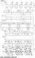
- FIG. 2 is a schematic diagram of the draw texturing machine 1, expanded along paths of yarns Y (yarn paths).
- FIG. 3 is a view of a winding unit, viewed along an arrow III in FIG. 1 .
- the draw texturing machine 1 can perform false twisting of a yarn Y made of synthetic fibers such as nylon (polyamide fibers).
- the draw texturing machine 1 includes a yarn supplying unit 2 for supplying the yarns Y, a processing unit 3 which performs the false twisting of the yarns Y supplied from the supplying unit 2, and a winding unit 4 which winds the yarns Y processed by the processing unit 3 onto a winding bobbins Bw.
- Component of the yarn supplying unit 2, the processing unit 3, and the winding unit 4 are aligned to form plural lines (as shown in FIG. 2 ) in the base longitudinal direction orthogonal to a yarn running surface (sheet of FIG. 1 ) on which yarn paths from the yarn supplying unit 2 to the winding unit 4 through the processing unit 3 are provided.
- the yarn supplying unit 2 includes a creel stand 7 retaining yarn supply packages Ps, and supplies the yarns Y to the processing unit 3.
- the following members are placed in this order from the upstream in a yarn running direction: first feed rollers 11; twist-stopping guides 12; first heaters 13; coolers 14; five-axial false-twisting devices 15; second feed rollers 16; combining units 17; third feed rollers 18; a second heater 19; and fourth feed rollers 20.
- the winding unit 4 winds the yarns Y for which the false winding has been performed at the processing unit 3 onto the winding bobbins Bw by winding devices 21, and forms wound packages Pw.
- the draw texturing machine 1 includes a main base 8 and a winding base 9 which are placed to be spaced apart from each other in the base width direction.
- the main base 8 and the winding base 9 are provided to extend in a substantially same length in the base longitudinal direction, and placed to oppose each other.
- An upper part of the main base 8 is connected to an upper part of the winding base 9 by a supporting frame 10.
- Each device forming the processing unit 3 is mainly attached to the main base 8 or the supporting frame 10.
- the main base 8, the winding base 9, and the supporting frame 10 form a working space 22 in which an operator performs an operation such as the yarn threading to each device.
- the yarn paths are formed so that the yarns Y mainly run around the working space 22.
- the draw texturing machine 1 includes units which are termed spans each of which includes a pair of the main base 8 and the winding base 9 placed to oppose each other.
- each device is placed so that the yarns Y running while being aligned in the base longitudinal direction can be false-twisted at the same time.
- twelve winding devices 21 are provided for one winding base 9 (as shown in FIG. 3 ).
- one winding device 21 can wind a yarn Y or two yarns Y at the same time as described below.
- twenty four yarns Y can be simultaneously wound at maximum in one span.
- the spans are placed in a left-right symmetrical manner to the sheet, with a center line C of the base width direction of the main base 8 as a symmetry axis (main base 8 is shared between the left span and the right span), and the spans are aligned in the base longitudinal direction.
- the structure of the processing unit 3 will be described with reference to FIG. 1 and FIG. 2 .
- Each first feed roller 11 sends the yarns Y supplied from the yarn supplying unit 2 to the first heater 13.
- the first feed rollers 11 are placed above the winding base 9 (as shown in FIG. 1 ).
- the first feed rollers 11 are aligned in the base longitudinal direction.
- each first feed roller 11 can send the two yarns Y to the first heater 13.
- the disclosure is not limited to this.
- Each twist-stopping guide 12 prevents twisting which has been applied to the yarn Y at the five-axial false-twisting device 15 from being propagated to the upstream of each twist-stopping guide 12 in the yarn running direction.
- the twist-stopping guides 12 are placed downstream of the first feed rollers 11 in the yarn running direction, and placed upstream of the first heater 13 in the yarn running direction.
- the twist-stopping guides 12 are, for example, provided for the yarns Y supplied from the yarn supplying unit 2, respectively, and aligned in the base longitudinal direction.
- Each first heater 13 heats the yarns Y sent from the first feed rollers 11, and are placed at the supporting frame 10 (as shown in FIG. 1 ).
- the first heaters 13 are provided for the yarns Y supplied from the yarn supplying unit 2, and aligned in the base longitudinal direction.
- each first heater 13 can heat four yarns Y.
- the disclosure is not limited to this.
- Each cooler 14 cools the yarns Y heated at each first heater 13.
- the coolers 14 are placed downstream of each first heater 13 in the yarn running direction, and placed upstream of the five-axial false-twisting devices 15 in the yarn running direction.
- the coolers 14 can cool the yarns Y by airflow.
- the coolers 14 are provided for the yarns Y supplied by the yarn supplying unit 2, and aligned in the base longitudinal direction.
- each cooler 14 can cool four yarns Y.
- the disclosure is not limited to this.
- the five-axial false-twisting devices 15 are a kind of a false-twisting device having a disc-friction system, and each five-axial false-twisting device 15 simultaneously twists two yarns Y, i.e., a yarn Y1 (first yarn of the present invention) and a yarn Y2 (second yarn of the present invention) in the same direction.
- the five-axial false-twisting devices 15 are placed directly downstream of the coolers 14 in the yarn running direction.
- the five-axial false-twisting devices 15 are aligned in the base longitudinal direction.
- the five-axial false-twisting device 15 which is placed at an end portion in the base longitudinal direction, only one yarn Y is threaded (see the five-axial false-twisting device 15 at the left end portion of the sheet of FIG. 2 ).
- thirteen five-axial false-twisting devices 15 are provided in one span (not shown in the figure). The specific details of the five-axial false-twisting devices 15 will be given later.
- Each second feed roller 16 sends the yarns Y processed at the five-axial false-twisting devices 15 to the combining unit 17.
- the second feed rollers 16 are placed above the upper part of the main frame 8 (as shown in FIG. 1 ).
- the second feed rollers 16 are aligned in the base longitudinal direction.
- each second feed roller 16 can send two yarns Y to the combining unit 17.
- the disclosure is not limited to this.
- the second feed rollers 16 convey the yarns Y at a higher conveyance speed than the first feed rollers 11, and the yarns Y are drawn between the first feed rollers 11 and the second feed rollers 16.
- Each combining unit 17 can combine the yarn Y1 and the yarn Y2.
- each combining unit 17 can combine the following yarns Y: a yarn Y1 which is processed at one five-axial false-twisting device 15; and a yarn Y2 which is processed at another five-axial false-twisting device 15 placed adjacent to the five-axial false-twisting device 15 in the base longitudinal direction.
- the combining units 17 are placed below the second feed rollers 16 (as shown in FIG. 1 ).
- Each combining unit 17 includes two interlace nozzles 31 and 32 (as shown in FIG. 2 ).
- Each combining unit 17 blows air onto the yarn Y1 and the yarn Y2 (as shown at the left part of the sheet of FIG. 2 ) which are, for example, passing the inside of the interlace nozzle 31, and each combining unit 17 combines the yarn Y1 and the yarn Y2 by air-interlace which the yarn Y1 is interlaced with the yarn Y2 by airflow.
- each combining unit 17 can guide the two yarns Y to downstream in the yarn running direction, without combining the yarn Y1 and the yarn Y2.
- the yarn Y1 passes the inside of the interlace nozzle 31, and the yarn Y2 passes the inside of the interlace nozzle 32 (as shown on the right part of the sheet of FIG. 2 ).
- Each third feed roller 18 sends the yarns Y running downstream of each combining unit 17 in the yarn running direction to the second heater 19.
- the third feed rollers 18 are placed below the combining units 17 (as shown in FIG. 1 ).
- the third feed rollers 18 are aligned in the base longitudinal direction.
- each third feed roller 18 can send two yarns Y to the second heater 19.
- the disclosure is not limited to this.
- the second feed rollers 18 convey the yarns Y at a slower conveyance speed than the second feed rollers 16, and the yarns Y are relaxed between the second feed rollers 16 and the third feed rollers 18.
- the second heater 19 heats the yarns Y supplied from the third feed rollers 18.
- the second heater 19 is placed below the third feed rollers 18 (as shown in FIG. 1 ).
- the second heater 19 extends along the vertical direction, and one second heater 19 is provided in one span.
- Each fourth feed roller 20 sends the yarns Y heated by the second heater 19 to the winding device 21, and are placed at the lower part of the working space 22 (as shown in FIG. 1 ).
- the fourth feed rollers 20 are aligned in the base longitudinal direction.
- each fourth feed roller 20 can send two yarns Y to the winding device 21.
- the fourth feed rollers 20 convey the yarns Y at a slower conveyance speed than the third feed rollers 18, and the yarns Y are relaxed between the third feed rollers 18 and the fourth feed rollers 20.
- the two yarns Y (yarn Y1 and yarn Y2) false-twisted by each five-axial false-twisting device 15 are combined by the combining unit 17 while being relaxed between the second feed rollers 16 and the third feed rollers 18, the two yarns Y are guided to the downstream side in the yarn running direction.
- the two false-twisted yarns Y are guided to the downstream side in the yarn running direction without being combined.
- the yarn Y is thermally set at the second heater 19 while being relaxed between the third feed roller 18 and the fourth feed roller 20.
- the yarn Y sent from each fourth feed roller 20 is wound by each winding device 21, and forms each package Pw.
- the structure of the winding unit 4 will be described with reference to FIG. 2 and FIG. 3 .
- the winding unit 4 includes the winding devices 21 which wind the yarns Y onto the winding bobbins Bw.
- each winding device 21 can wind the yarn Y or the yarns Y onto the winding bobbin Bw or two winding bobbins Bw.
- Each winding device 21 includes fulcrum guides 41 which are fulcrums when the yarns Y are traversed, a traverse unit 42 which traverses the yarns Y, a single cradle 43 which supports the winding bobbins Bw to be rotatable, and a controller 44 (as shown in FIG. 3 ).
- each fulcrum guide 41 is a guide which is a fulcrum when the yarn Y is traversed.
- Three fulcrum guides 41 are provided at each winding device 21 to be aligned along, for example, the base longitudinal direction (as shown in FIG. 2 ).
- the yarn Y formed by yarn combination at the combining unit 17 is guided, the yarn Y is threaded to the central one among the three fulcrum guides 41 (as shown at the left part of the sheet of FIG. 2 ).
- the two yarns Y which are sent without being combined are guided, the two yarns Y are threaded to two fulcrum guides 41 at both ends among the three fulcrum guides 41, respectively (as shown at the right part of the sheet of FIG. 2 ).
- the traverse unit 42 can traverse the yarns Y by traverse guides 45 which are attached to an endless belt driven in a reciprocating manner by a motor.
- the number of the traverse guides 45 which are attached to the endless belt can be changed depending on the number of the yarns Y which are traversed.
- one traverse guide 45 is provided for the traverse unit 42 which traverses the yarn Y formed by yarn combination at one combining unit 17 (as shown at the left part of the sheet of FIG. 2 ).
- two traverse guides 45 are provided for the traverse unit 42 which traverses the yarns Y which are sent without being combined (as shown at the right part of the sheet of FIG. 2 ).
- a traveling range of the traverse guides 45 can be changed depending on the number of the yarns Y to be traversed.
- Information related to settings such as the number of the yarns Y which are traversed or the traveling range of the traverse guides 45 is stored in, for example, the controller 44.
- the cradle 43 can support one or more (one or two) winding bobbin Bw (wound package Pw) to be rotatable. In other words, the cradle 43 can be switched between a state of supporting one winding bobbin Bw and a state of supporting two winding bobbins Bw.
- the cradle 43 is provided at each winding device 21.
- a contact roller 46 which makes a contact with surfaces of the wound packages Pw is placed directly upstream of the wound packages Pw in the yarn running direction.
- the winding bobbins Bw which are supported by the cradle 43 are rotationally driven, for example, by an unillustrated motor.
- the contact roller 46 in contact with the surfaces of the wound packages Pw applies a contact pressure onto the wound packages Pw while being rotationally driven by friction.
- the contact roller 46 may be rotationally driven by an unillustrated motor.
- the wound packages Pw in contact with the contact roller 46 are rotationally driven by the friction.
- the controller 44 controls an operation of the traverse unit 42 and an operation of the motor which rotationally drives the winding bobbins Bw. In addition to that, the controller 44 can change the setting related to the number of the yarns Y which are wound onto one winding device 21. In this regard, the controller 44 can switch an operational mode between a first mode in which one yarn Y is wound onto one winding bobbin Bw (as shown at the left part of the sheet of FIG. 2 ) and a second mode in which two yarns Y are wound onto two winding bobbins Bw (as shown at the right part of the sheet of FIG. 2 ).
- the yarn Y which is sent from the fourth feed roller 20 described above is wound onto the winding bobbin Bw by each winding device 21, and forms each wound package Pw.
- the operational mode of the corresponding winding device 21 is set in the first mode.
- the operational mode of the corresponding winding device 21 is set in the second mode.
- FIG. 4 is a perspective view of the five-axial false-twisting device 15.
- FIG. 5 shows the five-axial false-twisting device 15 viewed in a direction orthogonal to both of a base longitudinal direction and an axial direction of a rotational shaft 53 described below (hereinafter, this direction will be simply referred to as an axial direction).
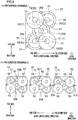
- FIGs. 6(a) and 6(b) show the five-axial false-twisting device 15 viewed in the axial direction, which applies Z-twisting to yarns Y.
- FIG. 7(a) and 7(b) show the five-axial false-twisting device 15 viewed in the axial direction, which applies S-twisting to yarns Y.
- FIG. 6(b) and FIG. 7(b) circular plate members 57 described below are indicated by two-dot chain lines so that supporting tables 54 to 56 described below are shown.
- One side and the other side in the base longitudinal direction are defined as shown in FIG. 4 to FIG. 7(b) .
- the side which is close to the working space 22 is defined as the near side (as shown in FIG. 1 , FIG. 4 , FIGs. 6(a) and 6(b) , and FIGs.
- FIG. 7(a) and 7(b) the side which is distant from the working space 22 is defined as the far side (as shown in FIG. 4 , FIGs. 6(a) and 6(b) , and FIGs. 7(a) and 7(b) ).
- a yarn guide 61 described below is not shown.
- Each five-axial false-twisting device 15 can twist (perform the Z-twisting or S-twisting on) two yarns Y (yarn Y1 and yarn Y2) in the same direction at the same time.
- a first false-twisting unit 51 which applies twisting to the yarn Y1 and a second false-twisting unit 52 which applies the twisting to the yarn Y2 are provided at the five-axial false-twisting device 15.
- the five-axial false-twisting devices 15 are aligned in the base longitudinal direction (as shown in FIG. 2 ).
- the five-axial false-twisting device 15 includes five rotational shafts 53, the supporting tables 54, 55, and 56, the circular plate members 57, a driving mechanism 58, and the yarn guides 61, 62, and 63, as components which form the first false-twisting unit 51 and the second false-twisting unit 52.
- the five rotational shafts 53 (common rotational shaft 71, first independent rotational shafts 72 and 73, second independent rotational shafts 74 and 75) are axial members which extend in the axial direction substantially orthogonal to the base longitudinal direction. In this regard, the axial direction may not necessarily be substantially orthogonal to the base longitudinal direction.
- the first false-twisting unit 51 includes the common rotational shaft 71 which is placed at the center in the base longitudinal direction and two first independent rotational shafts 72 and 73 which are placed on the one side in the base longitudinal direction of the common rotational shaft 71.
- the second false-twisting unit 52 includes the common rotational shaft 71 and two second independent rotational shafts 74 and 75 which are placed on the other side in the base longitudinal direction of the common rotational shaft 71.
- the common rotational shaft 71 is shared between the first false-twisting unit 51 and the second false-twisting unit 52. As shown in FIG. 6(a) and FIG.
- the rotational shafts 53 are placed so that the axial centers of these shafts form apexes of two virtual equilateral triangles (first triangle 201 and second triangle 202) when viewed in the axial direction.
- the common rotational shaft 71 and the first independent rotational shafts 72 and 73 form the apexes of the first triangle 201.
- the common rotational shaft 71 and the second independent rotational shafts 74 and 75 form the apexes of the second triangle 202.
- the first independent rotational shafts 72 and 73 oppose the second independent rotational shafts 74 and 75 over the common rotational shaft 71 in the base longitudinal direction.
- the supporting tables 54, 55, and 56 are tables supporting the rotational shafts 53 to be rotatable via unillustrated bearings.
- the supporting table 54 cantilevers, in a rotatable manner, the common rotational shaft 71, the first independent rotational shaft 72 which is placed on the far side among the first independent rotational shafts 72 and 73, and the second independent rotational shaft 74 which is placed on the far side among the second independent rotational shafts 74 and 75.
- the supporting table 55 is attached to the supporting table 54 and placed on the near side of the supporting table 54, and cantilevers the first independent rotational shaft 73 on the near side, in a rotatable manner.
- the supporting table 56 is attached to the supporting table 54 and placed on the near side of the supporting table 54, and cantilevers the second independent rotational shaft 75 of the near side, in a rotatable manner.
- the upper side of the sheet in FIG. 4 and FIG. 5 is a leading end side in the axial direction
- the lower side of the sheet is a base end side in the axial direction.
- the yarns Y run from the leading end side in the axial direction of the rotational shaft 53 to the base end side.
- the leading end side in the axial direction is the upstream side in the yarn running direction.
- the base end side in the axial direction is the downstream side in the yarn running direction.
- a running direction of a yarn Y1 is defined as a first yarn running direction
- a running direction of a yarn Y2 is defined as a second yarn running direction (as shown in FIG. 5 ).
- the Base end parts of the supporting tables 54, 55, and 56 in the axial direction are covers 54a, 55a, and 56a covering part of the driving mechanism 58, respectively (as shown in FIG. 4 and FIG. 5 ).
- the circular plate members 57 are members which are attached to each of the rotational shafts 53 and apply the twisting to yarns Y by making a contact with the yarns Y.
- the present embodiment assumes that the circular plate members 57 are attached to all rotational shafts 53 of all five-axial false-twisting devices 15, in order to simplify the description. Furthermore, in the present embodiment, three or four circular plate members 57 are attached to each of the rotational shafts 53 (as shown in, e.g., FIG. 4 ). However, the disclosure is not limited to this.
- circular plate members 57 which are attached to the common rotational shaft 71 and the first independent rotational shafts 72 and 73 are provided at the first false-twisting unit 51, and placed to form a spiral extending in the axial direction.
- the direction of the spiral formed by the circular plate members 57 is determined by the direction of the twisting performed on the yarns Y.
- the circular plate members 57 of the first false-twisting unit 51 are placed to form a spiral in a counterclockwise direction when a five-axial false-twisting device 15 which performs the Z-twisting on the yarns Y (five-axial false-twisting device 15a; as shown in FIGs.
- the circular plate members 57 of the first false-twisting unit 51 are placed to form a spiral in a clockwise direction when a five-axial false-twisting device 15 which performs the S-twisting on the yarns Y (five-axial false-twisting device 15b; as shown in FIGs. 7(a) and 7(b) ) is viewed from the leading end side in the axial direction.
- Circular plate members 57 which are attached to the common rotational shaft 71 and the second independent rotational shafts 74 and 75 are provided at the second false-twisting unit 52, and placed to form a spiral extending in the axial direction.
- the direction of the spiral formed by the circular plate members 57 provided at the second false-twisting unit 52 is identical with the direction of the spiral formed by the circular plate members 57 provided at the first false-twisting unit 51.
- the following members are placed in a first plane 203 orthogonal to the axial direction: a circular plate member 57 which is placed at the most upstream in the first yarn running direction of the first false-twisting unit 51(circular plate member 81); and a circular plate member 57 which is placed at the most upstream in the second yarn running direction of the second false-twisting unit 52 (circular plate member 82).
- a circular plate member 57 which is placed at the most upstream in the first yarn running direction of the first false-twisting unit 51(circular plate member 81); and a circular plate member 57 which is placed at the most upstream in the second yarn running direction of the second false-twisting unit 52 (circular plate member 82).
- the position of the circular plate member 81 in the axial direction and the position of the circular plate member 82 in the axial direction are substantially the same.
- a circular plate member 57 which is placed at the most downstream in the first yarn running direction of the first false-twisting unit 51 (circular plate member 83); and a circular plate member 57 which is placed at the most downstream in the second yarn running direction of the second false-twisting unit 52 (circular plate member 84).
- the position of the circular plate member 83 in the axial direction and the position of the circular plate member 84 in the axial direction are substantially the same.
- the circular plate members 57 of the first false-twisting unit 51 and the circular plate members 57 of the second false-twisting unit 52 are placed point-symmetrical about the common rotational shaft 71 as a symmetrical axis, when viewed in the axial direction.
- the circular plate member 81 of the first false-twisting unit 51 is attached to the first independent rotational shaft 73 on the near side.
- the circular plate member 82 of the second false-twisting unit 52 is attached to the second independent rotational shaft 74 on the far side.
- Contact parts where the circular plate members 57 makes a contact with the yarn Y are made of, for example, polyurethane.
- at least one circular plate member 57 which includes the contact part in contact with the yarn Y is made of polyurethane is attached to each of the rotational shafts 53.
- circular plate members 57 (circular plate members 81 and 82) with which the running yarn Y makes a contact at first and circular plate members 57 (circular plate members 83 and 84) with which the running yarn Y makes a contact at last are easily worn away.
- the contact parts of the circular plate members 81, 82, 83, and 84 in contact with the yarn Y are made of, for example, ceramic which has a higher abrasion resistance than polyurethane. Because of this, the circular plate members 81, 82, 83, and 84 are suppressed from being worn away.
- the disclosure is not limited to this. All contact parts of all circular plate members 57 in contact with the yarn Y may be made of polyurethane.
- the driving mechanism 58 is a mechanism which rotationally drives five rotational shafts 53 in the same direction.
- the driving mechanism 58 includes a motor 85 (as shown in FIG. 4 ; a drive source and a common driving source of the present invention), and belts 86, 87, 88, and 89 for transmitting the power of the motor 85 to each of the rotational shafts (as shown in FIG. 5 ).
- a driving mechanism 58 of the five-axial false-twisting device 15 (five-axial false-twisting device 15a) which performs the Z-twisting on the yarn Y rotationally drives the rotational shafts 53 counterclockwise (indicated by arrows in FIGs.
- a driving mechanism 58 of the five-axial false-twisting device 15 which performs the S-twisting on the yarn Y rotationally drives the rotational shafts 53 clockwise (indicated by arrows in FIGs. 7(a) and 7(b) ), when viewed from the leading end side in the axial direction.
- the specific details of the driving mechanism 58 will be described later.
- Two yarn guides 61, two yarn guides 62, and two yarn guides 63 are provided to correspond to the first false-twisting unit 51 and the second false-twisting unit 52, as shown in FIG. 5 .
- the yarn guide 61 of the first false-twisting unit 51 (yarn guide 61a; a first yarn guide of the present invention) is placed directly upstream of the circular plate member 81 in the first yarn running direction.
- the yarn guide 62 (yarn guide 62a) of the first false-twisting unit 51 is placed directly downstream of the circular plate member 83 in the first yarn running direction.
- the yarn guide 63 (yarn guide 63a) of the first false-twisting unit 51 is placed directly downstream of the yarn guide 62a in the first yarn running direction, and fixed to one end portion of the supporting table 55 in the base longitudinal direction.
- the yarn guide 61 of the second false-twisting unit 52 (yarn guide 61b; a second yarn guide of the present invention) is placed directly upstream of the circular plate member 82 in the second yarn running direction.
- the yarn guide 62 (yarn guide 62b) of the second false-twisting unit 52 is placed directly downstream of the circular plate member 84 in the second yarn running direction.
- the yarn guide 63 (yarn guide 63b) of the first false-twisting unit 52 is placed directly downstream of the yarn guide 62b in the second yarn running direction, and fixed to the other end portion of the supporting table 56 in the base longitudinal direction.
- the yarns Y are placed to form paths (yarn paths) described below.
- a yarn Y1 is placed to form a spiral while making a contact with the circular plate members 57 of the first false-twisting unit 51 via the yarn guide 61a.
- the yarn Y1 in contact with the circular plate members 57 is placed to be inside the first triangle 201 (as shown in FIG. 6(a) ) and runs through the inside of the first triangle 201, when viewed in the axial direction. Subsequently, the yarn Y1 runs toward the downstream side in the first yarn running direction via the yarn guides 62a and 63a.
- a yarn Y2 is placed to form a spiral while making a contact with the circular plate members 57 of the second false-twisting unit 52 via the yarn guide 61b.
- the yarn Y2 in contact with the circular plate members 57 is placed to be inside the second triangle 202 (as shown in FIG. 6(a) ) and runs through the inside of the second triangle 202, when viewed in the axial direction. Subsequently, the yarn Y2 runs toward the downstream side in the second yarn running direction via the yarn guides 62b and 63b.
- the driving mechanism 58 rotationally drives the five rotational shafts 53 in the same direction in order to apply the twisting to the yarns Y in contact with the rotating circular plate members 57.
- Z-twisting is applied to both of the yarn Y1 and the yarn Y2.
- S-twisting is applied to both of the yarn Y1 and the yarn Y2.
- the yarn Y1 needs to be introduced from a gap between predetermined two rotational shafts 53 into the inside of the first triangle 201, and then threaded to the yarn guides 61, 62, and 63.
- the yarn Y2 needs to be introduced from a gap between predetermined two rotational shafts 53 into the inside of the second triangle 202, and needs to be threaded to the yarn guides 61, 62, and 63.
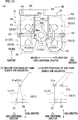
- the yarn threading is performed by an operator at the working space 22 (as shown in FIG. 1 ). As shown in a reference drawing in FIG.
- the first false-twisting unit 51 and the second false-twisting unit 52 need to be aligned in the base longitudinal direction so that both of the first false-twisting unit 51 and the second false-twisting unit 52 face the working space 22 (as shown in the reference drawing in FIG. 8(b) ).
- the circular plate members 57 of the first false-twisting unit 51 and the circular plate members 57 of the second false-twisting unit 52 are placed point-symmetrically with each other, when viewed in the axial direction.
- the first way is, as shown at the left part of the sheet of FIG. 8(b) , to perform the yarn threading on the first false-twisting unit 51 from the near side, and to perform the yarn threading on the second false-twisting unit 52 from the far side (as indicated by arrows 205 and 206 in FIG. 8(b) ).
- the second way is, as shown at the central part of the sheet of FIG. 8(b) , to perform the yarn threading on the first false-twisting unit 51 from the far side, and to perform the yarn threading on the second false-twisting unit 52 from the near side (as indicated by arrows 207 and 208 in FIG. 8(b) ).
- the third way is, as shown at the right part of the sheet of FIG. 8(b) , to perform the yarn threading on the first false-twisting unit 51 from one side in the base longitudinal direction, and to perform the yarn threading on the second false-twisting unit 52 from the other side in the base longitudinal direction (as indicated by arrows 209 and 210 in FIG. 8(b) ).
- the circular plate members 57 of the first false-twisting unit 51 and the circular plate members 57 of the second false-twisting unit 52 may not be placed point-symmetrically with each other.
- such an arrangement is unrealistic because of the following reasons.
- the positions of the circular plate members 57 of the first false-twisting unit 51 and the positions of the circular plate members 57 of the second false-twisting unit 52 are different from each other in the axial direction.
- the yarn quality of the yarn Y1 and the yarn quality of the yarn Y2 may be different from each other because the yarn path of the yarn Y1 and the yarn path of the yarn Y2 are very different.
- size of the device may be disadvantageously increased because the rotational shaft 53 is elongated.
- the circular plate members 57 of the first false-twisting unit 51 and the circular plate members 57 of the second false-twisting unit 52 need to be placed point-symmetrically with each other.
- the five-axial false-twisting device 15 needs to employ the third way.
- the five-axial false-twisting device 15 of the present embodiment is configured such that the yarn Y1 is threaded from a gap between two first independent rotational shafts 72 and 73 and the yarn Y2 is threaded from a gap between two second independent rotational shafts 74 and 75.
- the five-axial false-twisting device 15 has a structure described below in order to facilitate the yarn threading.
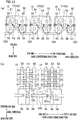
- FIG. 9(a) shows a five-axial false-twisting device 15 when the first independent rotational shaft 73 is placed at a first operating position (described below) and the second independent rotational shaft 75 is placed at a second operating position (described below).
- FIG. 9(b) shows a five-axial false-twisting device 15 when the first independent rotational shaft 73 is placed at a first yarn threading position (described below) and the second independent rotational shaft 75 is placed at a second yarn threading position (described below).
- the supporting table 55 which supports the first independent rotational shaft 73 placed on the near side among the first independent rotational shafts 72 and 73 (i.e., a first movable shaft placed on one side of the present invention) to be rotatable is attached to the supporting table 54 to be able to swing with an axial center of the common rotational shaft 71 as a swing shaft center.
- the supporting tables 54 and 55 are hinged to each other to be able to open and close. Because of this, the first independent rotational shaft 73 can move between the operating position (first operating position; as shown in FIG.
- the first independent rotational shaft 73 can change a distance to the first independent rotational shaft 72 while maintaining a distance to the common rotational shaft 71, when viewed in the axial direction.
- the supporting table 56 which supports the second independent rotational shaft 75 placed on the near side among the second independent rotational shafts 74 and 75 (one side, i.e., a second movable shaft of the present invention) to be rotatable is attached to the supporting table 54 to be able to swing with the axial center of the common rotational shaft 71 as the swing shaft center. Because of this, the second independent rotational shaft 75 can move between the operating position (second operating position; as shown in FIG.
- the yarn guide 63a is fixed to the supporting table 55, and the yarn guide 63b is fixed to the supporting table 56. Therefore, when the first independent rotational shaft 73 moves to the first yarn threading position from the first operating position, the yarn guide 63a also moves to the near side and to the inner side (common rotational shaft 71 side) in the base longitudinal direction of the five-axial false-twisting device 15 (as shown in FIG. 9(b) ).
- the yarn guide 63b also moves to the near side and to the inner side (common rotational shaft 71 side) in the base longitudinal direction of the five-axial false-twisting device 15 (as shown in FIG. 9(b) ). Yarn threading to the yarn guide 63 is facilitated because the yarn guides 63a and 63b (yarn guide 63) move to the near side (toward an operator).
- the yarn guide 63 moves to the inner side (common rotational shaft 71 side) in the base longitudinal direction of the five-axial false-twisting device 15 so that space between the yarn guide 63 of the five-axial false-twisting device 15 and a yarn guide 63 of an adjacent five-axial false-twisting device 15 is widened. Therefore, the yarn threading to the yarn guide 63 is further facilitated.
- a rotational angle of the supporting table 55 is, for example, 27° to 30°. Because the rotational angle described above is 27° or more, when the first independent rotational shaft 73 is placed at the first yarn threading position, the circular plate members 57 attached to the first independent rotational shaft 72 and the circular plate members 57 attached to the first independent rotational shaft 73 do not substantially overlap when viewed in the axial direction (as show in FIG. 9(b) ).
- the common rotational shaft 71, the first independent rotational shaft 72, and the second independent rotational shaft 74 are attached to the supporting table 54 to be rotatable, and are fixed in position.
- the common rotational shaft 71, the first independent rotational shaft 72, and the second independent rotational shaft 74 are equivalent to three fixed rotational shafts of the present invention.
- the first independent rotational shaft 73 and the second independent rotational shaft 75 are not equivalent to the three fixed rotational shafts of the present invention.
- FIG. 10(a) shows a guide supporter 90 (described below) viewed from the leading end side in the axial direction.
- FIG. 10(b) shows yarn paths viewed in the base longitudinal direction before positions of the yarn guides 61a and 61b are adjusted.
- FIG. 10(c) shows yarn paths viewed in the base longitudinal direction after the positions of the yarn guides 61a and 61b are adjusted.
- FIG. 11 shows a driving mechanism viewed from the base end side in the axial direction.
- the five-axial false-twisting device 15 includes the guide supporter 90 supporting the yarn guides 61a and 61b placed upstream in the yarn running direction.
- the guide supporter 90 includes, for example, a first supporting member 91 and a second supporting member 92.
- the first supporting member 91 is a member extending in the axial direction, and attached to a one side end of the supporting table 54 on the far side in the base longitudinal direction.
- the second supporting member 92 is a member attached to the leading end portion of the first supporting member 91 in the axial direction.
- the second supporting member 92 includes an extending portion 93 which extends to the inner side in the base longitudinal direction of the five-axial false-twisting device 15 and a pair of guide mounting portions 94a and 94b which are provided integrally with the extending portion 93 and extend in a direction substantially orthogonal to both of the axial direction and the base longitudinal direction.
- the guide mounting portion 94a is placed on one side (first false-twisting unit 51 side) in the base longitudinal direction of the five-axial false-twisting device 15.
- the guide mounting portion 94b is placed on the other side (second false-twisting unit 52 side) in the base longitudinal direction of the five-axial false-twisting device 15.
- an attachment hole 95a is formed at the guide mounting portion 94a in order to mount the yarn guide 61a
- an attachment hole 95b is formed at the guide mounting portion 94b in order to mount the yarn guide 61b.
- the yarn guide 61a is attached to the guide mounting portion 94a by a fastener 96a which includes an unillustrated screw passing through the attachment hole 95a.
- the yarn guide 61b is attached to the guide mounting portion 94b by a fastener 96b.
- the attachment holes 95a and 95b extend in a direction substantially orthogonal to both of the axial direction and the base longitudinal direction (as shown in FIG. 4 ).
- the yarn guides 61a and 61b are movable yarn guides which are able to be adjusted in position in a direction substantially orthogonal to the base longitudinal direction, when viewed in the axial direction.
- the yarn guide 61a can be moved along the attachment hole 95a when the fastener 96a is loosened.
- the yarn guide 61a can be fixed in position by fastening the fastener 96a.
- the yarn guide 61b is similarly arranged.
- the circular plate member 81 of the first false-twisting unit 51 and the circular plate member 82 of the second false-twisting unit 52 are placed point-symmetrically with each other (as shown in FIG. 6(a) ).
- the positions of the circular plate members 81 and 82 are different from each other when viewed in the base longitudinal direction. Therefore, as shown in FIG. 10(b) , a bending angle of the yarn Y1 running via the yarn guide 61a and a bending angle of the yarn Y2 running via the yarn guide 61b are different from each other if the yarn guides 61a and 61b are placed to overlap with each other when viewed in the base longitudinal direction.
- yarn quality of the yarn Y1 and yarn quality of the yarn Y2 may be different from each other.
- relative positional relationship between the yarn guides 61a and 61b can be adjusted because the yarn guides 61a and 61b are the movable yarn guides. Therefore, a gap between the bending angle of the yarn Y1 and the bending angle of the yarn Y2 can be reduced by adjusting the positions of the yarn guides 61a and 61b properly (as shown in FIG. 10(c) ).
- the driving mechanism 58 includes the motor 85 and belts 86, 87, 88, and 89.
- the motor 85 is placed on the farther side than the supporting table 54, and is a drive source for driving all of five rotational shafts.
- the belt 86 is an endless belt for transmitting the power of the motor 85 to the common rotational shaft 71 (intermediate shaft of the present invention).
- the belt 86 is wound around a pulley 101 attached to a drive shaft 85a of the motor 85 and a pulley 102 attached to the common rotational shaft 71.
- the belt 87 (common belt of the present invention) is an endless belt for transmitting the power of the motor 85, via the common rotational shaft 71, to the first independent rotational shaft 72 and the second independent rotational shaft 74 which are two of three fixed rotational shafts.
- the belt 87 is wound around a pulley 103 attached to the common rotational shaft 71, a pulley 104 attached to the first independent rotational shaft 72, and a pulley 105 attached to the second independent rotational shaft 74 (as shown in FIG. 5 and FIG. 11 ).
- the belt 88 is an endless belt for transmitting the power of the motor 85 to the first independent rotational shaft 73 via the common rotational shaft 71.
- the belt 88 is wound around a pulley 106 attached to the common rotational shaft 71 and a pulley 107 attached to the first independent rotational shaft 73 (as shown in FIG. 5 and FIG. 11 ).
- the belt 89 is an endless belt for transmitting the power of the motor 85 to the second independent rotational shaft 75 via the common rotational shaft 71.
- the belt 89 is wound around a pulley 108 attached to the common rotational shaft 71 and a pulley 109 attached to the second independent rotational shaft 75 (as shown in FIG. 5 and FIG. 11 ).
- a belt for transmitting the power to the first independent rotational shaft 72 and a belt for transmitting the power to the second independent rotational shaft 74 are provided individually instead of the belt 87 for driving both of the first independent rotational shaft 72 and the second independent rotational shaft 74, the number of belts is increased. As a result, the number of pulleys attached to the common rotational shaft 71 is increased, and the length of the common rotational shaft 71 is disadvantageously increased. In this regard, in the present embodiment, increase in number of belts is suppressed because the three fixed rotational shafts are driven together by the belt 87.
- the first independent rotational shaft 73 is movable between the first operating position and the first yarn threading position which is on the near side of the first operating position. Because of this, the space between two first independent rotational shafts 72 and 73 can be widened in the yarn threading to the first false-twisting unit 51. Therefore, in a structure in which the five-axial false-twisting devices 15 are aligned in the base longitudinal direction, the yarn threading from the working space 22 is facilitated.
- the second independent rotational shaft 75 is movable between the second operating position and the second yarn threading position, the space between the second independent rotational shafts 74 and 75 can be widened in the yarn threading to the second false-twisting unit 52. As described above, in the draw texturing machine 1 in which the five-axial false-twisting devices 15 are aligned in the base longitudinal direction, the yarn threading is facilitated.
- the first independent rotational shaft 73 and the second independent rotational shaft 75 can swing with the common rotational shaft 71 as the swing shaft center. In other words, the distance between the first independent rotational shaft 73 and the common rotational shaft 71 and the distance between the second independent rotational shaft 75 and the common rotational shaft 71 are not changed when the first independent rotational shaft 73 and the second independent rotational shaft 75 are moved. Therefore, it is possible to avoid damage of the belts 88 and 89 because of looseness or excessive tension.
- the positions of the yarn guides 61a and 61b are adjusted so that a difference between the yarn path of the yarn Y1 guided by the yarn guide 61a and the yarn path of the yarn Y2 guided by the yarn guide 61b is suppressed to be small. Therefore, the difference in quality between the yarn Y1 and the yarn Y2 is suppressed.
- the yarn guides 61a and 61b are movable in the direction substantially orthogonal to the base longitudinal direction, when viewed in the axial direction. Therefore, movable areas of the yarn guides 61a and 61b can be widened while the yarn guides 61a and 61b are suppressed from interfering with each other, so that the yarn paths are effectively adjusted.
- the belt 87 can drive the common rotational shaft 71, the first independent rotational shaft 72, and the second independent rotational shaft 74 together, increase in number of belts is suppressed. Therefore, increase in length of the rotational shaft 53 is suppressed, and increase in size of the device is suppressed.
- the power of the motor 85 is transmitted to the common rotational shaft 71 placed at the center in the base longitudinal direction among five rotational shafts 53. Because of this, the five-axial false-twisting device 15 can be configured to transmit the power further to the other rotational shafts 53 placed around the common rotational shaft 71. Therefore, the structure for transmitting of the power can be simplified.
- the circular plate member 81 placed at the most upstream in the first yarn running direction of the first false-twisting unit 51 and the circular plate member 82 placed at the most upstream in the second yarn running direction of the second false-twisting unit 52 are placed in the same first plane 203. Furthermore, the circular plate member 83 placed at the most downstream in the first yarn running direction of the first false-twisting unit 51 and the circular plate member 84 placed at the most downstream in the second yarn running direction of the second false-twisting unit 52 are placed in the same second plane 204. Because of this, the circular plate members 57 are small in size in the axial direction. Therefore, the increase in size of the device can be suppressed in the axial direction.
Landscapes
- Engineering & Computer Science (AREA)
- Mechanical Engineering (AREA)
- Textile Engineering (AREA)
- Yarns And Mechanical Finishing Of Yarns Or Ropes (AREA)
- Lubricants (AREA)
- Structure Of Belt Conveyors (AREA)
- Paper (AREA)
Abstract
Description
- The present invention relates to a draw texturing machine.
- A draw texturing machine recited in Patent Literature 1 (
Japanese Laid-Open Patent Publication No. 2016-141912 Japanese Laid-Open Patent Publication No. S62-199826 - In this stage, to suppress increase in size of the draw texturing machine and to process more yarns, a five-axial false-twisting device (as shown in
Patent Literature 3;Japanese Laid-Open Patent Publication No. S53-2656 - In the five-axial false-twisting device described above, yarn threading to the first false-twisting unit and the second false-twisting unit is needed. To be more specific, a yarn needs to be introduced from a gap between predetermined two rotational shafts into the inside of the triangle at each of the first false-twisting unit and the second false-twisting unit. Typically, the yarn threading is performed by an operator at a working space extending in the base longitudinal direction. In this stage, when one of the first false-twisting unit and the second false-twisting unit is placed on a side (far side) which is more distant from the working space than the other, it is very difficult to perform the yarn threading on the false-twisting unit on the far side. Therefore, the first false-twisting unit and the second false-twisting unit need to be aligned in the base longitudinal direction so that both of the first false-twisting unit and the second false-twisting unit face the working space.
- Furthermore, to perform the yarn threading on each false-twisting unit, a structure in which the yarn is introduced from a gap between the two rotational shafts placed on an outer side in the base longitudinal direction is needed (details will be described at the embodiment below). In the structure, when the yarn threading is performed on one five-axial false-twisting device, the working space between the five-axial false-twisting device and an adjacent five-axial false-twisting device placed adjacent in the base longitudinal direction may be narrow, and the yarn threading may be difficult.
- An object of the present invention is to facilitate yarn threading in a draw texturing machine in which five-axial false-twisting devices are aligned in a base longitudinal direction.
- A draw texturing machine according to a first aspect of the invention includes: five-axial false-twisting devices aligned in a base longitudinal direction, each of which being able to apply twisting to two yarns at the same time by circular plate members, the circular plate members being provided at five rotational shafts, the five rotational shafts extending in an axial direction orthogonal to the base longitudinal direction, and a working space being formed along the base longitudinal direction for yarn threading performed by the five-axial false-twisting devices, and each of the five-axial false-twisting devices includes: a first false-twisting unit which includes, among the five rotational shafts, two first independent rotational shafts and a common rotational shaft which virtually form apexes of a first triangle when viewed in the axial direction, the first false-twisting unit applying the twisting to a first yarn running inside of the first triangle; and a second-false twisting unit which includes, among the five-rotational shafts, two second independent rotational shafts and the common rotational shaft which virtually form apexes of a second triangle when viewed in the axial direction, the second false-twisting unit applying the twisting to a second yarn running inside of the second triangle, the two first independent rotational shafts opposing the two second independent rotational shafts over the common rotational shaft in the base longitudinal direction, the first false-twisting unit being configured such that the first yarn is threaded to the first false-twisting unit by being introduced from a gap between the two first independent rotational shafts into the inside of the first triangle, the second false-twisting unit being configured such that the second yarn is threaded to the second false-twisting unit by being introduced from a gap between the two second independent rotational shafts into the inside of the second triangle, one of the two first independent rotational shafts being a first movable shaft placed on a near side which is closer to the working space than the other of the two first independent rotational shafts, the one of the two first independent rotational shafts being movable between a first operating position in which each of the five-axial false-twisting devices is in operation and a first yarn threading position which is on the near side of the first operating position, and one of the two second independent rotational shafts being a second movable shaft placed on the near side of the other of the two second independent rotational shafts, the one of the two second independent rotational shafts being movable between a second operating position in which each of the five-axial false-twisting devices is in operation and a second yarn threading position which is on the near side of the second operating position.
- In the present invention, the first independent rotational shafts of the first false-twisting unit oppose the second independent rotational shafts of the second false-twisting unit over the common rotational shaft in the base longitudinal direction of the five-axial false-twisting device. In other words, the first false-twisting unit and the second false-twisting unit are aligned in the base longitudinal direction. Furthermore, the one of the two first independent rotational shafts is movable between the first operating position and the first yarn threading position which is on the near side of the first operating position. Because of this, a space between the two first independent rotational shafts can be widened in the yarn threading to the first false-twisting unit. Therefore, in a structure in which the five-axial false-twisting devices are aligned in the base longitudinal direction, the yarn threading from the working space is facilitated. Likewise, because the one of the two second independent rotational shafts is movable between the second operating position and the second yarn threading position, a space between the two second independent rotational shafts can be widened in the yarn threading to the second false-twisting unit. As described above, in the draw texturing machine in which the five-axial false-twisting devices are aligned in the base longitudinal direction, the yarn threading is facilitated.
- According to a second aspect of the invention, in the draw texturing machine of the first aspect, the first movable shaft and the second movable shaft are swingable with the common rotational shaft as a swing shaft center.
- Assume that the first and second movable shafts move and a distance between these movable shafts and the common rotational shaft changes. In this case, for example, when members (such as belts or gears) need to be lain between the movable shafts and the common rotational shaft in order to transmit power of a driving source, the following problems may occur. For example, when the distance changes in a state in which the belts are lain, the belts may loosen or have damaged because of excessive tension. When the distance changes in a state in which the gears are lain, accuracy of meshing may be decreased in meshing the gears together again.
- In the present invention, because the first movable shaft and the second movable shaft are swingable with the common rotational shaft as the swing shaft center, the movable shafts are movable without changing the distance between the movable shafts and the common rotational shaft. Therefore, it is possible to avoid occurrence of the problems described above.
- A third aspect of the invention, in the draw texturing machine of the first or second aspect, the first false-twisting unit further includes, a first yarn guide placed upstream of a circular plate member which is the most upstream circular plate member in a first yarn running direction in which the first yarn runs, among the circular plate members, the second false-twisting unit further includes, a second yarn guide placed upstream of a circular plate member which is the most upstream circular plate member in a second yarn running direction in which the second yarn runs, among the circular plate members, and at least one of the first yarn guide and the second yarn guide is a movable yarn guide which is able to be adjusted in position relative to the other.
- Generally, at each false-twisting unit, the circular plate members are placed to form a spiral. In this regard, by which rotational shaft is provided with the most upstream circular plate member placed in the yarn running direction, a yarn path of the first yarn guided by the first yarn guide and a yarn path of the second yarn guided by the second yarn guide may change. In this case, when the yarn path of the first yarn and the yarn path of the second yarn are significantly different, twisting of the first yarn and twisting of the second yarn may be different from each other because of difference in, e.g., bending angles between the yarns. As a result, yarn quality of the first yarn and yarn quality of the second yarn may be different from each other.
- In the present invention, the positions of the movable yarn guides are adjusted so that difference can be suppressed to be small between the yarn path of the first yarn guided by the first yarn guide and the yarn path of the second yarn guided by the second yarn guide. Therefore, the difference in quality can be suppressed between the first yarn and the second yarn.
- According to a fourth aspect of the invention, in the draw texturing machine of the third aspect, the first yarn guide and the second yarn guide are aligned in the base longitudinal direction, and the movable yarn guide is movable in a direction crossing the base longitudinal direction when viewed in the axial direction.
- For example, in a structure in which one of the first yarn guide and the second yarn guide is moved along the base longitudinal direction, movable areas may be narrow in order to avoid interference between the one of the first yarn guide and the second yarn guide and the other of the first yarn guide and the second yarn guide. In the present invention, the movable area of the movable yarn guide can be widened while the two yarn guides are suppressed from interfering with each other, so that the yarn paths are effectively adjusted.
- According to a fifth aspect of the invention, in the draw texturing machine of any one of the first to fourth aspects, each of the five-axial false-twisting devices is structured as power of a drive source is transmitted to, among the five rotational shafts, an intermediate shaft which is one of three fixed rotational shafts except the first movable shaft and the second movable shaft, and includes a common belt for transmitting the power of the drive source to the others of the three fixed rotational shafts from the intermediate shaft.
- In order to rotationally drive the rotational shafts by one driving source, preferably, belts making low noise and less vibration are used to transmit the power of the driving source. However, when the number of the belts are simply increased to depend on the number of the rotational shafts, the rotational shafts are elongated by increase in part in which the belts are wound around. As a result, size of the device may be disadvantageously increased in the axial direction. In the present invention, the number of the belts can be suppressed to be small because the three fixed rotational shafts are driven together by the common belt. Therefore, increase in length of the rotational shafts is suppressed, and increase in size of the device is suppressed.
- According to a sixth aspect of the invention, in the draw texturing machine of the fifth aspect, the intermediate shaft is the common rotational shaft.
- According to the positional relationship of the five rotational shafts described above, a common drive shaft is placed at the center of the five rotational shafts in the base longitudinal direction. In the present invention, to begin with, the power of the driving source is transmitted to the center common rotational shaft. Because of this, the five-axial false-twisting device can be configured to transmit the power further to the other rotational shafts placed around the common rotational shaft. Therefore, the structure for transmitting of the power can be simplified.
- According to a seventh aspect of the invention, in the draw texturing machine of any one of the first to sixth aspects, each of the five-axial false-twisting devices further includes a common driving source for driving the five rotational shafts together, and among the five rotational shafts, at a rotational shaft which is not used for processing the yarns, a weight is provided instead of at least one of the circular plate members.
- In the five-axial false-twisting device, two yarns may be twisted at the same time by both of the first false-twisting unit and the second false-twisting unit, or only one yarn may be twisted by one of the first false-twisting unit and the second false-twisting unit. From the perspective of cost reduction, when only one yarn is twisted, preferably, unnecessary circular plate members are detached from a rotational shaft which is not used for processing yarns. However, if the circular plate members are simply detached from some rotational shafts in one five-axial false-twisting device, a load on a common driving source of the one five-axial false-twisting device becomes smaller than a load on each of common driving sources of other five-axial false-twisting devices. Because of this, in the five-axial false-twisting device which some of the circular plate members are detached, five rotational shafts rotate unintentionally at high speed. As a result, yarn quality of yarns which are processed at the five-axial false-twisting device may be greatly different from yarn quality of yarns which are processed at other five-axial false-twisting devices.
- In the present invention, because the weights are provided in place of the unnecessary circular plate members, the rotational shafts are prevented from unintentionally rotating at high speed, thanks to these weights functioning as loads. Therefore, by using members which are more inexpensive than the circular plate members as the weights, the difference in yarn quality is suppressed between the five-axial false-twisting devices while increase in cost is suppressed.
- According to an eighth aspect of the invention, in the draw texturing machine of any one of the first to seventh aspects, at least one of the circular plate members provided at the common rotational shaft has higher abrasion resistance at a component which forms a contact part making a contact with the yarns than at least one of the circular plate members provided at a rotational shaft among the five rotational shafts except the common rotational shaft.
- With the circular plate members provided at the other rotational shafts except the common rotational shaft, only the first yarn or the second yarn makes a contact. Meanwhile, with circular plate members provided at the common rotational shaft, both of the first yarn and the second yarn make a contact. In other words, the circular plate members provided at the common rotational shaft may be worn away earlier than the circular plate members provided at the other rotational shafts. In this case, because the circular plate members provided at the common rotational shaft need to be replaced earlier than the other circular plate members, the labor of the replacement may be increased. In the present invention, because the circular plate members provided at the common rotational shaft have higher abrasion resistance than the other circular plate members, it is possible to suppress the circular plate members provided at the common rotational shaft from being worn away earlier than the other circular plate members. Therefore, it is possible to avoid the necessity of replacement of some circular plate members earlier than the other circular plate members.
- According to a ninth aspect of the invention, in the draw texturing machine of any one of the first to eighth aspects, a circular plate member placed at the most upstream in the first yarn running direction in which the first yarn runs in the first false-twisting unit and a circular plate member placed at the most upstream in the second yarn running direction in which the second yarn runs in the second false-twisting unit are placed in a same first plane which is orthogonal to the axial direction, and a circular plate member placed at the most downstream in the first yarn running direction in the first false-twisting unit and a circular plate member placed at the most downstream in the second yarn running direction in the second false-twisting unit are placed in a same second plane which is orthogonal to the axial direction.
- In a structure in which the most upstream circular plate member placed in the first yarn running direction and the most upstream circular plate member placed in the second yarn running direction are placed to be different in position from each other in the axial direction, at least some of the rotational shafts need to be elongated. As a result, firstly, the yarn path of the first yarn and the yarn path of the second yarn may change. When the yarn path of the first yarn and the yarn path of the second yarn are greatly different, twisting of the first yarn and twisting of the second yarn may be different from each other because of difference in, e.g., bending angles between the yarns. As a result, yarn quality of the first yarn and yarn quality of the second yarn may be different from each other. Secondly, the device may be increased in size in the axial direction. In positional relationship between the most downstream circular plate member placed in the first yarn running direction and the most downstream circular plate member placed in the second yarn running direction, the problems described above also occur. In the present invention, the circular plate members can be small in size in the axial direction in a state in which the yarn path of the first yarn and the yarn path of the second yarn are substantially the same. Therefore, the increase in size of the device can be suppressed in the axial direction. In addition to that, in the present invention, form of the yarn path of the first yarn and form of the yarn path of the second yarn can be moved closer to substantially the same when viewed in the base longitudinal direction.
-
-
FIG. 1 is a profile of a draw texturing machine related to an embodiment. -
FIG. 2 is a schematic diagram of the draw texturing machine, expanded along paths of yarns. -
FIG. 3 is a view of a winding unit, viewed along an arrow III inFIG. 1 . -
FIG. 4 is a perspective view of a five-axial false-twisting device. -
FIG. 5 shows the five-axial false-twisting device viewed in a direction orthogonal to both of a base longitudinal direction and an axial direction. -
FIGs. 6(a) and 6(b) are views of the five-axial false-twisting device viewed in the axial direction, which applies Z-twisting to yarns. -
FIGs. 7(a) and 7(b) are views of a five-axial false-twisting device viewed in the axial direction, which applies S-twisting to yarns. -
FIG. 8(a) is a reference drawing which shows directions of the five false-twisting device, andFIG. 8(b) is a reference drawing which shows a direction of yarn threading to the five-axial false-twisting device. -
FIGs. 9(a) and 9(b) show movements of rotational shafts. -
FIG. 10(a) shows a guide supporter, andFIGs. 10(b) and 10(c) show yarn paths. -
FIG. 11 shows a driving mechanism which rotates and drives the rotating shafts. -
FIGs. 12(a) and 12(b) show a five-axial false-twisting device related to a modification. -
FIGs. 13(a) and 13(b) show a five-axial false-twisting device related to another modification. - The following will describe an embodiment of the present invention. A vertical direction to the sheet of
FIG. 1 is defined as a base longitudinal direction, and a left-right direction to the sheet is defined as a base width direction. A direction orthogonal to the base longitudinal direction and the base width direction is defined as the up-down direction (vertical direction) in which the gravity acts. - To begin with, the following will describe an overall structure of a draw texturing machine with reference to
FIG. 1 to FIG. 3 .FIG. 1 is a profile of adraw texturing machine 1 of the present embodiment.FIG. 2 is a schematic diagram of thedraw texturing machine 1, expanded along paths of yarns Y (yarn paths).FIG. 3 is a view of a winding unit, viewed along an arrow III inFIG. 1 . - The
draw texturing machine 1 can perform false twisting of a yarn Y made of synthetic fibers such as nylon (polyamide fibers). Thedraw texturing machine 1 includes ayarn supplying unit 2 for supplying the yarns Y, aprocessing unit 3 which performs the false twisting of the yarns Y supplied from the supplyingunit 2, and a windingunit 4 which winds the yarns Y processed by theprocessing unit 3 onto a winding bobbins Bw. Component of theyarn supplying unit 2, theprocessing unit 3, and the windingunit 4 are aligned to form plural lines (as shown inFIG. 2 ) in the base longitudinal direction orthogonal to a yarn running surface (sheet ofFIG. 1 ) on which yarn paths from theyarn supplying unit 2 to the windingunit 4 through theprocessing unit 3 are provided. - The
yarn supplying unit 2 includes acreel stand 7 retaining yarn supply packages Ps, and supplies the yarns Y to theprocessing unit 3. In theprocessing unit 3, the following members are placed in this order from the upstream in a yarn running direction:first feed rollers 11; twist-stoppingguides 12;first heaters 13;coolers 14; five-axial false-twistingdevices 15;second feed rollers 16; combiningunits 17;third feed rollers 18; asecond heater 19; andfourth feed rollers 20. The windingunit 4 winds the yarns Y for which the false winding has been performed at theprocessing unit 3 onto the winding bobbins Bw by windingdevices 21, and forms wound packages Pw. - The
draw texturing machine 1 includes amain base 8 and a windingbase 9 which are placed to be spaced apart from each other in the base width direction. Themain base 8 and the windingbase 9 are provided to extend in a substantially same length in the base longitudinal direction, and placed to oppose each other. An upper part of themain base 8 is connected to an upper part of the windingbase 9 by a supportingframe 10. Each device forming theprocessing unit 3 is mainly attached to themain base 8 or the supportingframe 10. Themain base 8, the windingbase 9, and the supportingframe 10 form a workingspace 22 in which an operator performs an operation such as the yarn threading to each device. The yarn paths are formed so that the yarns Y mainly run around the workingspace 22. - The
draw texturing machine 1 includes units which are termed spans each of which includes a pair of themain base 8 and the windingbase 9 placed to oppose each other. In one span, each device is placed so that the yarns Y running while being aligned in the base longitudinal direction can be false-twisted at the same time. For example, twelve windingdevices 21 are provided for one winding base 9 (as shown inFIG. 3 ). In addition to that, one windingdevice 21 can wind a yarn Y or two yarns Y at the same time as described below. In other words, in the present embodiment, twenty four yarns Y can be simultaneously wound at maximum in one span. In thedraw texturing machine 1, the spans are placed in a left-right symmetrical manner to the sheet, with a center line C of the base width direction of themain base 8 as a symmetry axis (main base 8 is shared between the left span and the right span), and the spans are aligned in the base longitudinal direction. - The structure of the
processing unit 3 will be described with reference toFIG. 1 andFIG. 2 . - Each
first feed roller 11 sends the yarns Y supplied from theyarn supplying unit 2 to thefirst heater 13. Thefirst feed rollers 11 are placed above the winding base 9 (as shown inFIG. 1 ). Thefirst feed rollers 11 are aligned in the base longitudinal direction. For example, as shown inFIG. 2 , eachfirst feed roller 11 can send the two yarns Y to thefirst heater 13. However, the disclosure is not limited to this. - Each twist-stopping
guide 12 prevents twisting which has been applied to the yarn Y at the five-axial false-twistingdevice 15 from being propagated to the upstream of each twist-stoppingguide 12 in the yarn running direction. The twist-stoppingguides 12 are placed downstream of thefirst feed rollers 11 in the yarn running direction, and placed upstream of thefirst heater 13 in the yarn running direction. The twist-stoppingguides 12 are, for example, provided for the yarns Y supplied from theyarn supplying unit 2, respectively, and aligned in the base longitudinal direction. - Each
first heater 13 heats the yarns Y sent from thefirst feed rollers 11, and are placed at the supporting frame 10 (as shown inFIG. 1 ). Thefirst heaters 13 are provided for the yarns Y supplied from theyarn supplying unit 2, and aligned in the base longitudinal direction. For example, as shown inFIG. 2 , eachfirst heater 13 can heat four yarns Y. However, the disclosure is not limited to this. - Each cooler 14 cools the yarns Y heated at each
first heater 13. Thecoolers 14 are placed downstream of eachfirst heater 13 in the yarn running direction, and placed upstream of the five-axial false-twistingdevices 15 in the yarn running direction. For example, as recited inJapanese Laid-Open Patent Publication No. 2011-47074 coolers 14 can cool the yarns Y by airflow. Thecoolers 14 are provided for the yarns Y supplied by theyarn supplying unit 2, and aligned in the base longitudinal direction. For example, as shown inFIG. 2 , each cooler 14 can cool four yarns Y. However, the disclosure is not limited to this. - The five-axial false-twisting
devices 15 are a kind of a false-twisting device having a disc-friction system, and each five-axial false-twistingdevice 15 simultaneously twists two yarns Y, i.e., a yarn Y1 (first yarn of the present invention) and a yarn Y2 (second yarn of the present invention) in the same direction. The five-axial false-twistingdevices 15 are placed directly downstream of thecoolers 14 in the yarn running direction. The five-axial false-twistingdevices 15 are aligned in the base longitudinal direction. In this regard, to the five-axial false-twistingdevice 15 which is placed at an end portion in the base longitudinal direction, only one yarn Y is threaded (see the five-axial false-twistingdevice 15 at the left end portion of the sheet ofFIG. 2 ). For example, thirteen five-axial false-twistingdevices 15 are provided in one span (not shown in the figure). The specific details of the five-axial false-twistingdevices 15 will be given later. - Each
second feed roller 16 sends the yarns Y processed at the five-axial false-twistingdevices 15 to the combiningunit 17. Thesecond feed rollers 16 are placed above the upper part of the main frame 8 (as shown inFIG. 1 ). Thesecond feed rollers 16 are aligned in the base longitudinal direction. For example, as shown inFIG. 2 , eachsecond feed roller 16 can send two yarns Y to the combiningunit 17. However, the disclosure is not limited to this. In this regard, thesecond feed rollers 16 convey the yarns Y at a higher conveyance speed than thefirst feed rollers 11, and the yarns Y are drawn between thefirst feed rollers 11 and thesecond feed rollers 16. - Each combining
unit 17 can combine the yarn Y1 and the yarn Y2. In the present embodiment, each combiningunit 17 can combine the following yarns Y: a yarn Y1 which is processed at one five-axial false-twistingdevice 15; and a yarn Y2 which is processed at another five-axial false-twistingdevice 15 placed adjacent to the five-axial false-twistingdevice 15 in the base longitudinal direction. However, the disclosure is not limited to this. The combiningunits 17 are placed below the second feed rollers 16 (as shown inFIG. 1 ). Each combiningunit 17 includes twointerlace nozzles 31 and 32 (as shown inFIG. 2 ). Each combiningunit 17 blows air onto the yarn Y1 and the yarn Y2 (as shown at the left part of the sheet ofFIG. 2 ) which are, for example, passing the inside of theinterlace nozzle 31, and each combiningunit 17 combines the yarn Y1 and the yarn Y2 by air-interlace which the yarn Y1 is interlaced with the yarn Y2 by airflow. In this regard, each combiningunit 17 can guide the two yarns Y to downstream in the yarn running direction, without combining the yarn Y1 and the yarn Y2. In this case, the yarn Y1 passes the inside of theinterlace nozzle 31, and the yarn Y2 passes the inside of the interlace nozzle 32 (as shown on the right part of the sheet ofFIG. 2 ). - Each
third feed roller 18 sends the yarns Y running downstream of each combiningunit 17 in the yarn running direction to thesecond heater 19. Thethird feed rollers 18 are placed below the combining units 17 (as shown inFIG. 1 ). Thethird feed rollers 18 are aligned in the base longitudinal direction. For example, as shown inFIG. 2 , eachthird feed roller 18 can send two yarns Y to thesecond heater 19. However, the disclosure is not limited to this. In this regard, thesecond feed rollers 18 convey the yarns Y at a slower conveyance speed than thesecond feed rollers 16, and the yarns Y are relaxed between thesecond feed rollers 16 and thethird feed rollers 18. - The
second heater 19 heats the yarns Y supplied from thethird feed rollers 18. Thesecond heater 19 is placed below the third feed rollers 18 (as shown inFIG. 1 ). Thesecond heater 19 extends along the vertical direction, and onesecond heater 19 is provided in one span. - Each
fourth feed roller 20 sends the yarns Y heated by thesecond heater 19 to the windingdevice 21, and are placed at the lower part of the working space 22 (as shown inFIG. 1 ). Thefourth feed rollers 20 are aligned in the base longitudinal direction. For example, as shown inFIG. 2 , eachfourth feed roller 20 can send two yarns Y to the windingdevice 21. However, the disclosure is not limited to this. Thefourth feed rollers 20 convey the yarns Y at a slower conveyance speed than thethird feed rollers 18, and the yarns Y are relaxed between thethird feed rollers 18 and thefourth feed rollers 20. - In the
processing unit 3 described above, two yarns Y which have been drawn between thefirst feed rollers 11 and thesecond feed rollers 16 are twisted at each five-axial false-twistingdevice 15. The twisting formed by the five-axial false-twistingdevices 15 propagates to the twist-stoppingguides 12 but does not propagate to the upstream of the twist-stoppingguides 12 in the yarn running direction. The yarn Y which is twisted and drawn is heated at eachfirst heater 13 and thermally set. After that, the yarn Y is cooled at each cooler 14. The yarn Y is untwisted at the downstream of each five-axial false-twistingdevice 15. However, each filament is maintained to be wavy in shape on account of the thermal setting described above. Subsequently, after the two yarns Y (yarn Y1 and yarn Y2) false-twisted by each five-axial false-twistingdevice 15 are combined by the combiningunit 17 while being relaxed between thesecond feed rollers 16 and thethird feed rollers 18, the two yarns Y are guided to the downstream side in the yarn running direction. Alternatively, the two false-twisted yarns Y are guided to the downstream side in the yarn running direction without being combined. Furthermore, the yarn Y is thermally set at thesecond heater 19 while being relaxed between thethird feed roller 18 and thefourth feed roller 20. Finally, the yarn Y sent from eachfourth feed roller 20 is wound by each windingdevice 21, and forms each package Pw. - The structure of the winding
unit 4 will be described with reference toFIG. 2 andFIG. 3 . The windingunit 4 includes the windingdevices 21 which wind the yarns Y onto the winding bobbins Bw. For example, as recited inJapanese Laid-Open Patent Publication No. 2009-74219 device 21 can wind the yarn Y or the yarns Y onto the winding bobbin Bw or two winding bobbins Bw. Each windingdevice 21 includes fulcrum guides 41 which are fulcrums when the yarns Y are traversed, atraverse unit 42 which traverses the yarns Y, asingle cradle 43 which supports the winding bobbins Bw to be rotatable, and a controller 44 (as shown inFIG. 3 ). - As described above, each
fulcrum guide 41 is a guide which is a fulcrum when the yarn Y is traversed. Three fulcrum guides 41 are provided at each windingdevice 21 to be aligned along, for example, the base longitudinal direction (as shown inFIG. 2 ). For example, when the yarn Y formed by yarn combination at the combiningunit 17 is guided, the yarn Y is threaded to the central one among the three fulcrum guides 41 (as shown at the left part of the sheet ofFIG. 2 ). When two yarns Y which are sent without being combined are guided, the two yarns Y are threaded to two fulcrum guides 41 at both ends among the three fulcrum guides 41, respectively (as shown at the right part of the sheet ofFIG. 2 ). - For example, the
traverse unit 42 can traverse the yarns Y by traverse guides 45 which are attached to an endless belt driven in a reciprocating manner by a motor. The number of the traverse guides 45 which are attached to the endless belt can be changed depending on the number of the yarns Y which are traversed. For example, onetraverse guide 45 is provided for thetraverse unit 42 which traverses the yarn Y formed by yarn combination at one combining unit 17 (as shown at the left part of the sheet ofFIG. 2 ). Meanwhile, two traverse guides 45 are provided for thetraverse unit 42 which traverses the yarns Y which are sent without being combined (as shown at the right part of the sheet ofFIG. 2 ). A traveling range of the traverse guides 45 can be changed depending on the number of the yarns Y to be traversed. Information related to settings such as the number of the yarns Y which are traversed or the traveling range of the traverse guides 45 is stored in, for example, thecontroller 44. - The
cradle 43 can support one or more (one or two) winding bobbin Bw (wound package Pw) to be rotatable. In other words, thecradle 43 can be switched between a state of supporting one winding bobbin Bw and a state of supporting two winding bobbins Bw. Thecradle 43 is provided at each windingdevice 21. Acontact roller 46 which makes a contact with surfaces of the wound packages Pw is placed directly upstream of the wound packages Pw in the yarn running direction. The winding bobbins Bw which are supported by thecradle 43 are rotationally driven, for example, by an unillustrated motor. In the structure described above, thecontact roller 46 in contact with the surfaces of the wound packages Pw applies a contact pressure onto the wound packages Pw while being rotationally driven by friction. Alternatively, instead of rotationally driving the winding bobbins Bw by a motor, thecontact roller 46 may be rotationally driven by an unillustrated motor. In the structure described above, the wound packages Pw in contact with thecontact roller 46 are rotationally driven by the friction. - The
controller 44 controls an operation of thetraverse unit 42 and an operation of the motor which rotationally drives the winding bobbins Bw. In addition to that, thecontroller 44 can change the setting related to the number of the yarns Y which are wound onto one windingdevice 21. In this regard, thecontroller 44 can switch an operational mode between a first mode in which one yarn Y is wound onto one winding bobbin Bw (as shown at the left part of the sheet ofFIG. 2 ) and a second mode in which two yarns Y are wound onto two winding bobbins Bw (as shown at the right part of the sheet ofFIG. 2 ). - In the winding
unit 4 structured as above, the yarn Y which is sent from thefourth feed roller 20 described above is wound onto the winding bobbin Bw by each windingdevice 21, and forms each wound package Pw. When two yarns Y are combined by one combiningunit 17, the operational mode of the corresponding windingdevice 21 is set in the first mode. In addition to that, when the two yarns Y are guided to the downstream side in the yarn running direction without being combined, the operational mode of the corresponding windingdevice 21 is set in the second mode. - The structure of the five-axial false-twisting
device 15 will be described with reference toFIG. 4 to FIG. 7(b) .FIG. 4 is a perspective view of the five-axial false-twistingdevice 15.FIG. 5 shows the five-axial false-twistingdevice 15 viewed in a direction orthogonal to both of a base longitudinal direction and an axial direction of arotational shaft 53 described below (hereinafter, this direction will be simply referred to as an axial direction).FIGs. 6(a) and 6(b) show the five-axial false-twistingdevice 15 viewed in the axial direction, which applies Z-twisting to yarns Y.FIGs. 7(a) and 7(b) show the five-axial false-twistingdevice 15 viewed in the axial direction, which applies S-twisting to yarns Y. InFIG. 6(b) andFIG. 7(b) ,circular plate members 57 described below are indicated by two-dot chain lines so that supporting tables 54 to 56 described below are shown. One side and the other side in the base longitudinal direction are defined as shown inFIG. 4 to FIG. 7(b) . In the five-axial false-twistingdevice 15, the side which is close to the working space 22 (as shown inFIG. 1 ) is defined as the near side (as shown inFIG. 1 ,FIG. 4 ,FIGs. 6(a) and 6(b) , andFIGs. 7(a) and 7(b) ), and the side which is distant from the workingspace 22 is defined as the far side (as shown inFIG. 4 ,FIGs. 6(a) and 6(b) , andFIGs. 7(a) and 7(b) ). InFIG. 6(a) to FIG. 7(b) , ayarn guide 61 described below is not shown. - Each five-axial false-twisting
device 15 can twist (perform the Z-twisting or S-twisting on) two yarns Y (yarn Y1 and yarn Y2) in the same direction at the same time. In other words, as shown inFIG. 4 to FIG. 7(b) , a first false-twistingunit 51 which applies twisting to the yarn Y1 and a second false-twistingunit 52 which applies the twisting to the yarn Y2 are provided at the five-axial false-twistingdevice 15. The five-axial false-twistingdevices 15 are aligned in the base longitudinal direction (as shown inFIG. 2 ). - As shown in
FIG. 4 to FIG. 7(b) , the five-axial false-twistingdevice 15 includes fiverotational shafts 53, the supporting tables 54, 55, and 56, thecircular plate members 57, adriving mechanism 58, and the yarn guides 61, 62, and 63, as components which form the first false-twistingunit 51 and the second false-twistingunit 52. The five rotational shafts 53 (commonrotational shaft 71, first independentrotational shafts rotational shafts 74 and 75) are axial members which extend in the axial direction substantially orthogonal to the base longitudinal direction. In this regard, the axial direction may not necessarily be substantially orthogonal to the base longitudinal direction. Among the fiverotational shafts 53, the first false-twistingunit 51 includes the commonrotational shaft 71 which is placed at the center in the base longitudinal direction and two first independentrotational shafts rotational shaft 71. The second false-twistingunit 52 includes the commonrotational shaft 71 and two second independentrotational shafts rotational shaft 71. In other words, the commonrotational shaft 71 is shared between the first false-twistingunit 51 and the second false-twistingunit 52. As shown inFIG. 6(a) andFIG. 7(a) , therotational shafts 53 are placed so that the axial centers of these shafts form apexes of two virtual equilateral triangles (first triangle 201 and second triangle 202) when viewed in the axial direction. The commonrotational shaft 71 and the first independentrotational shafts first triangle 201. The commonrotational shaft 71 and the second independentrotational shafts second triangle 202. The first independentrotational shafts rotational shafts rotational shaft 71 in the base longitudinal direction. - The supporting tables 54, 55, and 56 are tables supporting the
rotational shafts 53 to be rotatable via unillustrated bearings. The supporting table 54 cantilevers, in a rotatable manner, the commonrotational shaft 71, the first independentrotational shaft 72 which is placed on the far side among the first independentrotational shafts rotational shaft 74 which is placed on the far side among the second independentrotational shafts rotational shaft 73 on the near side, in a rotatable manner. The supporting table 56 is attached to the supporting table 54 and placed on the near side of the supporting table 54, and cantilevers the second independentrotational shaft 75 of the near side, in a rotatable manner. The upper side of the sheet inFIG. 4 andFIG. 5 is a leading end side in the axial direction, and the lower side of the sheet is a base end side in the axial direction. The yarns Y run from the leading end side in the axial direction of therotational shaft 53 to the base end side. In other words, the leading end side in the axial direction is the upstream side in the yarn running direction. The base end side in the axial direction is the downstream side in the yarn running direction. A running direction of a yarn Y1 is defined as a first yarn running direction, and a running direction of a yarn Y2 is defined as a second yarn running direction (as shown inFIG. 5 ). The Base end parts of the supporting tables 54, 55, and 56 in the axial direction arecovers driving mechanism 58, respectively (as shown inFIG. 4 andFIG. 5 ). - The
circular plate members 57 are members which are attached to each of therotational shafts 53 and apply the twisting to yarns Y by making a contact with the yarns Y. The present embodiment assumes that thecircular plate members 57 are attached to allrotational shafts 53 of all five-axial false-twistingdevices 15, in order to simplify the description. Furthermore, in the present embodiment, three or fourcircular plate members 57 are attached to each of the rotational shafts 53 (as shown in, e.g.,FIG. 4 ). However, the disclosure is not limited to this. - To begin with, among the
circular plate members 57,circular plate members 57 which are attached to the commonrotational shaft 71 and the first independentrotational shafts unit 51, and placed to form a spiral extending in the axial direction. The direction of the spiral formed by thecircular plate members 57 is determined by the direction of the twisting performed on the yarns Y. In other words, thecircular plate members 57 of the first false-twistingunit 51 are placed to form a spiral in a counterclockwise direction when a five-axial false-twistingdevice 15 which performs the Z-twisting on the yarns Y (five-axial false-twistingdevice 15a; as shown inFIGs. 6(a) and 6(b) ) is viewed from the leading end side in the axial direction. On the other hand, thecircular plate members 57 of the first false-twistingunit 51 are placed to form a spiral in a clockwise direction when a five-axial false-twistingdevice 15 which performs the S-twisting on the yarns Y (five-axial false-twistingdevice 15b; as shown inFIGs. 7(a) and 7(b) ) is viewed from the leading end side in the axial direction. -
Circular plate members 57 which are attached to the commonrotational shaft 71 and the second independentrotational shafts unit 52, and placed to form a spiral extending in the axial direction. The direction of the spiral formed by thecircular plate members 57 provided at the second false-twistingunit 52 is identical with the direction of the spiral formed by thecircular plate members 57 provided at the first false-twistingunit 51. - As shown in
FIG. 5 , the following members are placed in afirst plane 203 orthogonal to the axial direction: acircular plate member 57 which is placed at the most upstream in the first yarn running direction of the first false-twisting unit 51(circular plate member 81); and acircular plate member 57 which is placed at the most upstream in the second yarn running direction of the second false-twisting unit 52 (circular plate member 82). In other words, the position of thecircular plate member 81 in the axial direction and the position of thecircular plate member 82 in the axial direction are substantially the same. In addition to that, the following members are placed in asecond plane 204 orthogonal to the axial direction: acircular plate member 57 which is placed at the most downstream in the first yarn running direction of the first false-twisting unit 51 (circular plate member 83); and acircular plate member 57 which is placed at the most downstream in the second yarn running direction of the second false-twisting unit 52 (circular plate member 84). In other words, the position of thecircular plate member 83 in the axial direction and the position of thecircular plate member 84 in the axial direction are substantially the same. Because of this, increase in length of each of therotational shafts 53 is suppressed as compared with cases in which the positions of thecircular plate member 81 and thecircular plate member 82 are different in the axial direction or the positions of thecircular plate member 83 and thecircular plate member 84 are different in the axial direction. - The
circular plate members 57 of the first false-twistingunit 51 and thecircular plate members 57 of the second false-twistingunit 52 are placed point-symmetrical about the commonrotational shaft 71 as a symmetrical axis, when viewed in the axial direction. For a specific example, in the five-axial false-twistingdevice 15a (as shown inFIGs. 6(a) and 6(b) ), thecircular plate member 81 of the first false-twistingunit 51 is attached to the first independentrotational shaft 73 on the near side. In addition to that, thecircular plate member 82 of the second false-twistingunit 52 is attached to the second independentrotational shaft 74 on the far side. - Contact parts where the
circular plate members 57 makes a contact with the yarn Y are made of, for example, polyurethane. In the present embodiment, at least onecircular plate member 57 which includes the contact part in contact with the yarn Y is made of polyurethane is attached to each of therotational shafts 53. Meanwhile, circular plate members 57 (circular plate members 81 and 82) with which the running yarn Y makes a contact at first and circular plate members 57 (circular plate members 83 and 84) with which the running yarn Y makes a contact at last are easily worn away. Therefore, the contact parts of thecircular plate members circular plate members circular plate members 57 in contact with the yarn Y may be made of polyurethane. - The
driving mechanism 58 is a mechanism which rotationally drives fiverotational shafts 53 in the same direction. Thedriving mechanism 58 includes a motor 85 (as shown inFIG. 4 ; a drive source and a common driving source of the present invention), andbelts motor 85 to each of the rotational shafts (as shown inFIG. 5 ). Adriving mechanism 58 of the five-axial false-twisting device 15 (five-axial false-twistingdevice 15a) which performs the Z-twisting on the yarn Y rotationally drives therotational shafts 53 counterclockwise (indicated by arrows inFIGs. 6(a) and 6(b) ), when viewed from the leading end side in the axial direction. Adriving mechanism 58 of the five-axial false-twisting device 15 (five-axial false-twistingdevice 15b) which performs the S-twisting on the yarn Y rotationally drives therotational shafts 53 clockwise (indicated by arrows inFIGs. 7(a) and 7(b) ), when viewed from the leading end side in the axial direction. The specific details of thedriving mechanism 58 will be described later. - Two yarn guides 61, two yarn guides 62, and two yarn guides 63 are provided to correspond to the first false-twisting
unit 51 and the second false-twistingunit 52, as shown inFIG. 5 . To begin with, theyarn guide 61 of the first false-twisting unit 51 (yarn guide 61a; a first yarn guide of the present invention) is placed directly upstream of thecircular plate member 81 in the first yarn running direction. The yarn guide 62 (yarn guide 62a) of the first false-twistingunit 51 is placed directly downstream of thecircular plate member 83 in the first yarn running direction. The yarn guide 63 (yarn guide 63a) of the first false-twistingunit 51 is placed directly downstream of theyarn guide 62a in the first yarn running direction, and fixed to one end portion of the supporting table 55 in the base longitudinal direction. In addition to that, theyarn guide 61 of the second false-twisting unit 52 (yarn guide 61b; a second yarn guide of the present invention) is placed directly upstream of thecircular plate member 82 in the second yarn running direction. The yarn guide 62 (yarn guide 62b) of the second false-twistingunit 52 is placed directly downstream of thecircular plate member 84 in the second yarn running direction. The yarn guide 63 (yarn guide 63b) of the first false-twistingunit 52 is placed directly downstream of theyarn guide 62b in the second yarn running direction, and fixed to the other end portion of the supporting table 56 in the base longitudinal direction. - In the five-axial false-twisting
device 15 structured as described above, the yarns Y are placed to form paths (yarn paths) described below. As shown inFIG. 5 , to begin with, a yarn Y1 is placed to form a spiral while making a contact with thecircular plate members 57 of the first false-twistingunit 51 via theyarn guide 61a. The yarn Y1 in contact with thecircular plate members 57 is placed to be inside the first triangle 201 (as shown inFIG. 6(a) ) and runs through the inside of thefirst triangle 201, when viewed in the axial direction. Subsequently, the yarn Y1 runs toward the downstream side in the first yarn running direction via the yarn guides 62a and 63a. A yarn Y2 is placed to form a spiral while making a contact with thecircular plate members 57 of the second false-twistingunit 52 via theyarn guide 61b. The yarn Y2 in contact with thecircular plate members 57 is placed to be inside the second triangle 202 (as shown inFIG. 6(a) ) and runs through the inside of thesecond triangle 202, when viewed in the axial direction. Subsequently, the yarn Y2 runs toward the downstream side in the second yarn running direction via the yarn guides 62b and 63b. - While causing the yarns Y to run as described above, the
driving mechanism 58 rotationally drives the fiverotational shafts 53 in the same direction in order to apply the twisting to the yarns Y in contact with the rotatingcircular plate members 57. To be more specific, in the five-axial false-twistingdevice 15a for the Z-twisting (as shown inFIGs. 6(a) and 6(b) ), Z-twisting is applied to both of the yarn Y1 and the yarn Y2. In the five-axial false-twistingdevice 15b for the S-twisting (as shown inFIGs. 7(a) and 7(b) ), S-twisting is applied to both of the yarn Y1 and the yarn Y2. - In the five-axial false-twisting
device 15 described above, yarn threading to the first false-twistingunit 51 and the second false-twistingunit 52 is needed. To be more specific, the yarn Y1 needs to be introduced from a gap between predetermined tworotational shafts 53 into the inside of thefirst triangle 201, and then threaded to the yarn guides 61, 62, and 63. The yarn Y2 needs to be introduced from a gap between predetermined tworotational shafts 53 into the inside of thesecond triangle 202, and needs to be threaded to the yarn guides 61, 62, and 63. The yarn threading is performed by an operator at the working space 22 (as shown inFIG. 1 ). As shown in a reference drawing inFIG. 8(a) , if one of the first false-twistingunit 51 and the second false-twistingunit 52 is placed on the far side which is more distant than the other (distant from the working space 22), it is very difficult to perform the yarn threading on the false-twisting unit on the far side (second false-twistingunit 52 inFIG. 8(a) ). Therefore, the first false-twistingunit 51 and the second false-twistingunit 52 need to be aligned in the base longitudinal direction so that both of the first false-twistingunit 51 and the second false-twistingunit 52 face the working space 22 (as shown in the reference drawing inFIG. 8(b) ). - As described above, the
circular plate members 57 of the first false-twistingunit 51 and thecircular plate members 57 of the second false-twistingunit 52 are placed point-symmetrically with each other, when viewed in the axial direction. In this structure, there are three ways of the yarn threading to thecircular plate members 57 as shown inFIG. 8(b) . The first way is, as shown at the left part of the sheet ofFIG. 8(b) , to perform the yarn threading on the first false-twistingunit 51 from the near side, and to perform the yarn threading on the second false-twistingunit 52 from the far side (as indicated byarrows FIG. 8(b) ). The second way is, as shown at the central part of the sheet ofFIG. 8(b) , to perform the yarn threading on the first false-twistingunit 51 from the far side, and to perform the yarn threading on the second false-twistingunit 52 from the near side (as indicated byarrows FIG. 8(b) ). The third way is, as shown at the right part of the sheet ofFIG. 8(b) , to perform the yarn threading on the first false-twistingunit 51 from one side in the base longitudinal direction, and to perform the yarn threading on the second false-twistingunit 52 from the other side in the base longitudinal direction (as indicated byarrows FIG. 8(b) ). In this regard, to find another way to perform the yarn threading, thecircular plate members 57 of the first false-twistingunit 51 and thecircular plate members 57 of the second false-twistingunit 52 may not be placed point-symmetrically with each other. However, such an arrangement is unrealistic because of the following reasons. When thecircular plate members 57 of the first false-twistingunit 51 and thecircular plate members 57 of the second false-twistingunit 52 are placed not point-symmetrically with each other, the positions of thecircular plate members 57 of the first false-twistingunit 51 and the positions of thecircular plate members 57 of the second false-twistingunit 52 are different from each other in the axial direction. In this case, the yarn quality of the yarn Y1 and the yarn quality of the yarn Y2 may be different from each other because the yarn path of the yarn Y1 and the yarn path of the yarn Y2 are very different. In addition to that, size of the device may be disadvantageously increased because therotational shaft 53 is elongated. As described above, in reality, thecircular plate members 57 of the first false-twistingunit 51 and thecircular plate members 57 of the second false-twistingunit 52 need to be placed point-symmetrically with each other. - Among the three ways described above, the first and second ways are unrealistic because the yarn threading from the far side is difficult. Therefore, the five-axial false-twisting
device 15 needs to employ the third way. To be more specific, the five-axial false-twistingdevice 15 of the present embodiment is configured such that the yarn Y1 is threaded from a gap between two first independentrotational shafts rotational shafts device 15, a working space between the five-axial false-twistingdevice 15 and another five-axial false-twistingdevice 15 which is an adjacent device in the base longitudinal direction may be narrow (as shown inFIG. 8(b) ), and the yarn threading may be difficult. Therefore, in the present embodiment, the five-axial false-twistingdevice 15 has a structure described below in order to facilitate the yarn threading. - The specific details of the five-axial false-twisting
device 15 will be described with reference toFIGs. 9(a) and 9(b). FIG. 9(a) shows a five-axial false-twistingdevice 15 when the first independentrotational shaft 73 is placed at a first operating position (described below) and the second independentrotational shaft 75 is placed at a second operating position (described below).FIG. 9(b) shows a five-axial false-twistingdevice 15 when the first independentrotational shaft 73 is placed at a first yarn threading position (described below) and the second independentrotational shaft 75 is placed at a second yarn threading position (described below). - The supporting table 55 which supports the first independent
rotational shaft 73 placed on the near side among the first independentrotational shafts 72 and 73 (i.e., a first movable shaft placed on one side of the present invention) to be rotatable is attached to the supporting table 54 to be able to swing with an axial center of the commonrotational shaft 71 as a swing shaft center. In other words, the supporting tables 54 and 55 are hinged to each other to be able to open and close. Because of this, the first independentrotational shaft 73 can move between the operating position (first operating position; as shown inFIG. 9(a) ) where the five-axial false-twistingdevice 15 is in operation (applying the twisting on the yarns Y) and the threading position (first yarn threading position; as shown inFIG. 9(b) ) which is on the near side of the first operating position. Because of this, a space between two first independentrotational shafts devices 15 are aligned in the base longitudinal direction, yarn threading of the yarn Y1 from the workingspace 22 is facilitated (indicated by anarrow 211 inFIG. 9(b) ). To be more specific, the first independentrotational shaft 73 can change a distance to the first independentrotational shaft 72 while maintaining a distance to the commonrotational shaft 71, when viewed in the axial direction. Likewise, the supporting table 56 which supports the second independentrotational shaft 75 placed on the near side among the second independentrotational shafts 74 and 75 (one side, i.e., a second movable shaft of the present invention) to be rotatable is attached to the supporting table 54 to be able to swing with the axial center of the commonrotational shaft 71 as the swing shaft center. Because of this, the second independentrotational shaft 75 can move between the operating position (second operating position; as shown inFIG. 9(a) ) when the five-axial false-twistingdevice 15 is in operation and the yarn threading position (second yarn threading position; as shown inFIG. 9(b) ) which is on the near side of the second operating position. Because of this, a space between two second independentrotational shafts devices 15 are aligned in the base longitudinal direction, yarn threading of the yarn Y2 from the workingspace 22 is facilitated (indicated by anarrow 212 inFIG. 9(b) ). In this way, the yarn threading to the five-axial false-twistingdevice 15 is facilitated. In this regard, the supporting tables 54, 55, and 56 may support the commonrotational shaft 71 to be rotatable through an unillustrated bearing. - When the first independent
rotational shaft 73 and the second independentrotational shaft 75 are moved to the yarn threading positions from the operating positions, theserotational shafts 53 move to the near side and to the inner side in the base longitudinal direction of the five-axial false-twisting device 15 (commonrotational shaft 71 side). Therefore, it is possible to avoid interference between the five-axial false-twistingdevices 15 which are placed adjacent to each other in the base longitudinal direction, in the yarn threading. In other words, the space between the five-axial false-twistingdevices 15 does not need to be widened in order to allow the first independentrotational shaft 73 and the second independentrotational shaft 75 to be movable. Therefore, increase in size of thedraw texturing machine 1 in the base longitudinal direction is suppressed, and the yarn threading is facilitated. - In addition to that, as described above, the
yarn guide 63a is fixed to the supporting table 55, and theyarn guide 63b is fixed to the supporting table 56. Therefore, when the first independentrotational shaft 73 moves to the first yarn threading position from the first operating position, theyarn guide 63a also moves to the near side and to the inner side (commonrotational shaft 71 side) in the base longitudinal direction of the five-axial false-twisting device 15 (as shown inFIG. 9(b) ). Furthermore, when the second independentrotational shaft 75 moves to the second yarn threading position from the second operating position, theyarn guide 63b also moves to the near side and to the inner side (commonrotational shaft 71 side) in the base longitudinal direction of the five-axial false-twisting device 15 (as shown inFIG. 9(b) ). Yarn threading to theyarn guide 63 is facilitated because the yarn guides 63a and 63b (yarn guide 63) move to the near side (toward an operator). Furthermore, theyarn guide 63 moves to the inner side (commonrotational shaft 71 side) in the base longitudinal direction of the five-axial false-twistingdevice 15 so that space between theyarn guide 63 of the five-axial false-twistingdevice 15 and ayarn guide 63 of an adjacent five-axial false-twistingdevice 15 is widened. Therefore, the yarn threading to theyarn guide 63 is further facilitated. - In this stage, preferably, when the first independent
rotational shaft 73 is moved to the first yarn threading position from the first operating position, a rotational angle of the supporting table 55 is, for example, 27° to 30°. Because the rotational angle described above is 27° or more, when the first independentrotational shaft 73 is placed at the first yarn threading position, thecircular plate members 57 attached to the first independentrotational shaft 72 and thecircular plate members 57 attached to the first independentrotational shaft 73 do not substantially overlap when viewed in the axial direction (as show inFIG. 9(b) ). Therefore, the following operations are facilitated: to introduce the yarn Y1 from a gap between the first independentrotational shafts first triangle 201; and to perform the yarn threading to the yarn guides 61, 62, and 63. Furthermore, because the rotational angle is 30° or less, a problem such that the supporting tables 55 and 56 interfere with each other and unintentionally move is suppressed, and the yarn threading is smoothly performed. A rotational angle of the supporting table 56 when the second independentrotational shaft 75 is moved to the second yarn threading position from the second operating position is similarly arranged. - The common
rotational shaft 71, the first independentrotational shaft 72, and the second independentrotational shaft 74 are attached to the supporting table 54 to be rotatable, and are fixed in position. In other words, among fiverotational shafts 53, the commonrotational shaft 71, the first independentrotational shaft 72, and the second independentrotational shaft 74 are equivalent to three fixed rotational shafts of the present invention. The first independentrotational shaft 73 and the second independentrotational shaft 75 are not equivalent to the three fixed rotational shafts of the present invention. - Other structures of the five-axial false-twisting
device 15 will be described with reference to, e.g.,FIGs. 10(a) to 10(c) andFIG. 11 .FIG. 10(a) shows a guide supporter 90 (described below) viewed from the leading end side in the axial direction.FIG. 10(b) shows yarn paths viewed in the base longitudinal direction before positions of the yarn guides 61a and 61b are adjusted.FIG. 10(c) shows yarn paths viewed in the base longitudinal direction after the positions of the yarn guides 61a and 61b are adjusted.FIG. 11 shows a driving mechanism viewed from the base end side in the axial direction. - The structure of the yarn guides 61a and 61b and its surroundings will be described. As shown in
FIG. 4 andFIG. 10(a) , the five-axial false-twistingdevice 15 includes theguide supporter 90 supporting the yarn guides 61a and 61b placed upstream in the yarn running direction. Theguide supporter 90 includes, for example, a first supportingmember 91 and a second supportingmember 92. The first supportingmember 91 is a member extending in the axial direction, and attached to a one side end of the supporting table 54 on the far side in the base longitudinal direction. The second supportingmember 92 is a member attached to the leading end portion of the first supportingmember 91 in the axial direction. The second supportingmember 92 includes an extendingportion 93 which extends to the inner side in the base longitudinal direction of the five-axial false-twistingdevice 15 and a pair ofguide mounting portions portion 93 and extend in a direction substantially orthogonal to both of the axial direction and the base longitudinal direction. Theguide mounting portion 94a is placed on one side (first false-twistingunit 51 side) in the base longitudinal direction of the five-axial false-twistingdevice 15. Theguide mounting portion 94b is placed on the other side (second false-twistingunit 52 side) in the base longitudinal direction of the five-axial false-twistingdevice 15. - As shown in
FIG. 4 , anattachment hole 95a is formed at theguide mounting portion 94a in order to mount theyarn guide 61a, and anattachment hole 95b is formed at theguide mounting portion 94b in order to mount theyarn guide 61b. In addition to that, as shown inFIG. 10(a) , theyarn guide 61a is attached to theguide mounting portion 94a by afastener 96a which includes an unillustrated screw passing through theattachment hole 95a. Likewise, theyarn guide 61b is attached to theguide mounting portion 94b by afastener 96b. Furthermore, the attachment holes 95a and 95b extend in a direction substantially orthogonal to both of the axial direction and the base longitudinal direction (as shown inFIG. 4 ). Because of this, the yarn guides 61a and 61b are movable yarn guides which are able to be adjusted in position in a direction substantially orthogonal to the base longitudinal direction, when viewed in the axial direction. To be more specific, theyarn guide 61a can be moved along theattachment hole 95a when thefastener 96a is loosened. Theyarn guide 61a can be fixed in position by fastening thefastener 96a. Theyarn guide 61b is similarly arranged. - As described above, the
circular plate member 81 of the first false-twistingunit 51 and thecircular plate member 82 of the second false-twistingunit 52 are placed point-symmetrically with each other (as shown inFIG. 6(a) ). In other words, the positions of thecircular plate members FIG. 10(b) , a bending angle of the yarn Y1 running via theyarn guide 61a and a bending angle of the yarn Y2 running via theyarn guide 61b are different from each other if the yarn guides 61a and 61b are placed to overlap with each other when viewed in the base longitudinal direction. In this case, yarn quality of the yarn Y1 and yarn quality of the yarn Y2 may be different from each other. In this regard, in the present embodiment, relative positional relationship between the yarn guides 61a and 61b can be adjusted because the yarn guides 61a and 61b are the movable yarn guides. Therefore, a gap between the bending angle of the yarn Y1 and the bending angle of the yarn Y2 can be reduced by adjusting the positions of the yarn guides 61a and 61b properly (as shown inFIG. 10(c) ). - The following will describe the
driving mechanism 58 in a detailed manner. As shown inFIG. 11 , thedriving mechanism 58 includes themotor 85 andbelts motor 85 is placed on the farther side than the supporting table 54, and is a drive source for driving all of five rotational shafts. Thebelt 86 is an endless belt for transmitting the power of themotor 85 to the common rotational shaft 71 (intermediate shaft of the present invention). Thebelt 86 is wound around apulley 101 attached to adrive shaft 85a of themotor 85 and apulley 102 attached to the commonrotational shaft 71. - The belt 87 (common belt of the present invention) is an endless belt for transmitting the power of the
motor 85, via the commonrotational shaft 71, to the first independentrotational shaft 72 and the second independentrotational shaft 74 which are two of three fixed rotational shafts. Thebelt 87 is wound around apulley 103 attached to the commonrotational shaft 71, apulley 104 attached to the first independentrotational shaft 72, and apulley 105 attached to the second independent rotational shaft 74 (as shown inFIG. 5 andFIG. 11 ). - The
belt 88 is an endless belt for transmitting the power of themotor 85 to the first independentrotational shaft 73 via the commonrotational shaft 71. Thebelt 88 is wound around apulley 106 attached to the commonrotational shaft 71 and apulley 107 attached to the first independent rotational shaft 73 (as shown inFIG. 5 andFIG. 11 ). Thebelt 89 is an endless belt for transmitting the power of themotor 85 to the second independentrotational shaft 75 via the commonrotational shaft 71. Thebelt 89 is wound around apulley 108 attached to the commonrotational shaft 71 and apulley 109 attached to the second independent rotational shaft 75 (as shown inFIG. 5 andFIG. 11 ). - If a belt for transmitting the power to the first independent
rotational shaft 72 and a belt for transmitting the power to the second independentrotational shaft 74 are provided individually instead of thebelt 87 for driving both of the first independentrotational shaft 72 and the second independentrotational shaft 74, the number of belts is increased. As a result, the number of pulleys attached to the commonrotational shaft 71 is increased, and the length of the commonrotational shaft 71 is disadvantageously increased. In this regard, in the present embodiment, increase in number of belts is suppressed because the three fixed rotational shafts are driven together by thebelt 87. - As described above, the first independent
rotational shaft 73 is movable between the first operating position and the first yarn threading position which is on the near side of the first operating position. Because of this, the space between two first independentrotational shafts unit 51. Therefore, in a structure in which the five-axial false-twistingdevices 15 are aligned in the base longitudinal direction, the yarn threading from the workingspace 22 is facilitated. Likewise, because the second independentrotational shaft 75 is movable between the second operating position and the second yarn threading position, the space between the second independentrotational shafts unit 52. As described above, in thedraw texturing machine 1 in which the five-axial false-twistingdevices 15 are aligned in the base longitudinal direction, the yarn threading is facilitated. - The first independent
rotational shaft 73 and the second independentrotational shaft 75 can swing with the commonrotational shaft 71 as the swing shaft center. In other words, the distance between the first independentrotational shaft 73 and the commonrotational shaft 71 and the distance between the second independentrotational shaft 75 and the commonrotational shaft 71 are not changed when the first independentrotational shaft 73 and the second independentrotational shaft 75 are moved. Therefore, it is possible to avoid damage of thebelts - The positions of the yarn guides 61a and 61b are adjusted so that a difference between the yarn path of the yarn Y1 guided by the
yarn guide 61a and the yarn path of the yarn Y2 guided by theyarn guide 61b is suppressed to be small. Therefore, the difference in quality between the yarn Y1 and the yarn Y2 is suppressed. - The yarn guides 61a and 61b are movable in the direction substantially orthogonal to the base longitudinal direction, when viewed in the axial direction. Therefore, movable areas of the yarn guides 61a and 61b can be widened while the yarn guides 61a and 61b are suppressed from interfering with each other, so that the yarn paths are effectively adjusted.
- Because the
belt 87 can drive the commonrotational shaft 71, the first independentrotational shaft 72, and the second independentrotational shaft 74 together, increase in number of belts is suppressed. Therefore, increase in length of therotational shaft 53 is suppressed, and increase in size of the device is suppressed. - The power of the
motor 85 is transmitted to the commonrotational shaft 71 placed at the center in the base longitudinal direction among fiverotational shafts 53. Because of this, the five-axial false-twistingdevice 15 can be configured to transmit the power further to the otherrotational shafts 53 placed around the commonrotational shaft 71. Therefore, the structure for transmitting of the power can be simplified. - The
circular plate member 81 placed at the most upstream in the first yarn running direction of the first false-twistingunit 51 and thecircular plate member 82 placed at the most upstream in the second yarn running direction of the second false-twistingunit 52 are placed in the samefirst plane 203. Furthermore, thecircular plate member 83 placed at the most downstream in the first yarn running direction of the first false-twistingunit 51 and thecircular plate member 84 placed at the most downstream in the second yarn running direction of the second false-twistingunit 52 are placed in the samesecond plane 204. Because of this, thecircular plate members 57 are small in size in the axial direction. Therefore, the increase in size of the device can be suppressed in the axial direction. - The following will describe modifications of the above-described embodiment. The members identical with those in the embodiment above will be denoted by the same reference numerals, and the explanations thereof are not repeated.
- (1) In the present embodiment, in the
draw texturing machine 1, thecircular plate members 57 are attached to allrotational shafts 53 of all five-axial false-twistingdevices 15. However, the disclosure is not limited to this. An unnecessarycircular plate member 57 may be detached from arotational shaft 53 which is not used for processing yarns Y (for example, some of therotational shafts 53 of the five-axial false-twistingdevice 15 placed at the most left part inFIG. 2 ), for an object such as cost reduction. In this regard, in a structure in which fiverotational shafts 53 are driven together by the above-describedmotor 85, the following problems may occur. Ifcircular plate members 57 are simply detached from somerotational shafts 53 in one five-axial false-twistingdevice 15, a load on themotor 85 of the five-axial false-twistingdevice 15 becomes smaller than a load on each ofmotors 85 of other five-axial false-twistingdevices 15. Because of this, in the five-axial false-twistingdevice 15 from which some of thecircular plate members 57 are detached, fiverotational shafts 53 rotate unintentionally at high speed. As a result, yarn quality of yarns which are processed at the five-axial false-twistingdevice 15 may be greatly different from yarn quality of yarns which are processed at other five-axial false-twistingdevices 15. In this regard, as shown inFIGs. 12(a) and 12(b) , in the five-axial false-twistingdevice 15 from which some of thecircular plate members 57 are detached, weights may be provided in place of the detachedcircular plate members 57. For example, as shown inFIG. 12(a) , in a five-axial false-twisting device 15c in whichcircular plate members 57 are detached from first independentrotational shafts weights 110 may be provided in place of thecircular plate members 57. Likewise, as shown inFIG. 12(b) , in a five-axial false-twistingdevice 15d in whichcircular plate members 57 are detached from second independentrotational shafts weights 110 may be provided in place of thecircular plate members 57. Because of this, therotational shafts 53 are prevented from rotating unintentionally at high speed, thanks to theseweights 110 functioning as loads. Therefore, by using members which are more inexpensive than thecircular plate members 57 as theweights 110, the difference in yarn quality between the five-axial false-twistingdevices 15 is suppressed while increase in cost is suppressed.
Alternatively, instead of providing theweights 110, the five-axial false-twistingdevice 15 from which some of thecircular plate members 57 are detached may perform feedback control on the number of rotations of themotor 85. For example, the five-axial false-twistingdevice 15 may include an unillustrated inverter device for controlling the number of rotations of themotor 85 which drives fiverotational shafts 53 together. Alternatively, as another way, the five-axial false-twistingdevice 15 from which some of thecircular plate members 57 are detached may include five unillustrated motors which rotationally drive therotational shafts 53 individually. - (2) In the embodiment above, the
circular plate members 57, which include the contact parts making a contact with the yarns Y and being made of polyurethane, are attached to each of therotation shafts 53. However, the disclosure is not limited to this. In other words, both of the yarn Y1 and the yarn Y2 make a contact with thecircular plate members 57 provided at the commonrotational shaft 71 in principle, so that thesecircular plate members 57 may be worn away earlier than the othercircular plate members 57 provided to otherrotational shafts 53. For this reason, for example, the contact parts, making a contact with the yarns Y, of all of thecircular plate members 57 attached to the commonrotational shaft 71 may be made of ceramic which has higher abrasion resistance than polyurethane. In other words, the abrasion resistance of the contact parts, making a contact with the yarns Y, of thecircular plate members 57 attached to the commonrotational shaft 71 may be higher than the abrasion resistance of the contact parts, making a contact with the yarn Y, of thecircular plate members 57 attached to otherrotational shafts 53 except the commonrotational shaft 71. Because of this, it is possible to suppress thecircular plate members 57 provided at the commonrotational shaft 71 from being worn earlier than the othercircular plate members 57. Therefore, it is possible to avoid the necessity of replacement of somecircular plate members 57 earlier than the othercircular plate members 57. In this regard, materials of the contact parts, making a contact with the yarns Y, of thecircular plate members 57 are not limited to the above-described polyurethane or ceramic. - (3) In the present embodiment, the
circular plate member 81 of the first false-twistingunit 51 and thecircular plate member 82 of the second false-twistingunit 52 are placed in the samefirst plane 203. However, the disclosure is not limited to this. Thecircular plate members circular plate member 83 of the first false-twistingunit 51 and thecircular plate member 84 of the second false-twistingunit 52 may not be necessarily placed in the samesecond plane 204. - (4) In the present embodiment, by the
belt 86, the power is transmitted to the commonrotational shaft 71 from the motor 85 (i.e., the commonrotational shaft 71 is equivalent to the intermediate shaft of the present invention). However, the disclosure is not limited to this. For example, by thebelt 86, the five-axial false-twistingdevice 15 may be structured so that the power is transmitted to the first independentrotational shaft 72 or the second independentrotational shaft 74 from themotor 85. - (5) In the present embodiment, by the
belt 87, the power is transmitted to the first independentrotational shaft 72 and the second independentrotational shaft 74 through the commonrotational shaft 71. However, the disclosure is not limited to this. In other words, the power transmitted to the commonrotational shaft 71 may be transmitted to the first independentrotational shaft 72 and the second independentrotational shaft 74 through individual belts, respectively. - (6) In the present embodiment, the
rotational shafts 53 are driven by belts. However, the disclosure is not limited to this. For example, gears or chains may be provided instead of the belts, as transmission members which transmit power of the drive source to each of therotational shafts 53. - (7) In the present embodiment, the yarn guides 61a and 61b are movable in the direction orthogonal to the base longitudinal direction, when viewed in the axial direction. However, the disclosure is not limited to this. A movable direction of the yarn guides 61a and 61b may be tilted from the direction orthogonal to the base longitudinal direction. In other words, the yarn guides 61a and 61b may be movable in a direction crossing the base longitudinal direction.
- (8) In the embodiment described above, both of the yarn guides 61a and 61b can be adjusted in position. However, the disclosure is not limited to this. That is to say, only one of the yarn guides 61a and 61b may be adjustable in position relative to the other. In other words, at least one of the yarn guides 61a and 61b may be adjustable in position relative to the other.
- (9) In the modification described in the (8), at least one of the yarn guides 61a and 61b may be able to be adjusted in position relative to the other. However, the disclosure is not limited to this. The yarn guides 61a and 61b may not be necessarily able to be adjusted in position.
- (10) In the present embodiment, the first independent
rotational shaft 73 and the second independentrotational shaft 75 are able to swing with the commonrotational shaft 71 as the swing shaft center. However, the disclosure is not limited to this. For example, the first independentrotational shaft 73 and the second independentrotational shaft 75 may be movable linearly. - (11) In the present embodiment, the
draw texturing machine 1 includes the combiningunits 17. However, thedraw texturing machine 1 may not include the combiningunits 17. - (12) In the present embodiment, the winding
device 21 can switch the operational mode between the first mode in which the yarn Y is wound to one winding bobbin Bw and the second mode in which the yarns Y are wound to two winding bobbins Bw. However, the disclosure is not limited to this. For example, the windingdevice 21 may be able to select an operational mode in which the yarns Y are wound to three or more winding bobbins Bw. Alternatively, the windingdevice 21 may wind the yarn Y to only one winding bobbin Bw. - (13) In the embodiment described above, the
draw texturing machine 1 performs the false twisting on the yarns Y made of nylon. However, the disclosure is not limited to this. For example, thedraw texturing machine 1 may perform false twisting on yarns made of, e.g., polyester. - (14) In the structure in which the common
rotational shaft 71 is supported to be rotatable by the supporting tables 54, 55, and 56 via the unillustrated bearings, when, for example, the supporting table 55 is swung, the supporting table 56 may be passively swung with friction unintentionally and the following problem may occur. For example, in a case in which the yarn threading to the second false-twistingunit 52 has been completed already and the supporting table 56 is unintentionally swung to the near side, the yarn Y2 may be accidentally detached from the second false-twistingunit 52, and the yarn threading may be necessarily performed again. In this connection, the five-axial false-twistingdevice 15 may include a locking mechanism for preventing therotational shaft 53 from moving unintentionally to the yarn threading position from the operating position. All components of one locking mechanism may be provided at one corresponding five-axial false-twistingdevice 15. Alternatively, as shown inFIGs. 13(a) and 13(b) , alocking mechanism 120 may be provided across a supporting table 55 of one five-axial false-twistingdevice 15 and a supporting table 56 of an adjacent five-axial false-twistingdevice 15 placed adjacent to the one five-axial false-twistingdevice 15. To be more specific, as shown inFIG. 13(b) , thelocking mechanism 120 includes along plate member 121, arotation shaft 122 provided at a near-side surface of a supporting table 56 of one five-axial false-twistingdevice 15, and a protrudingportion 123 provided at a near-side surface of a supporting table 55 of an adjacent five-axial false-twistingdevice 15. One end portion of theplate member 121 in an extending direction is attached to the near-side surface of the supporting table 56 via therotation shaft 122. In other words, theplate member 121 is attached to the supporting table 56 to be rotatable. The other end portion of theplate member 121 in the extending direction is provided with, e.g., aU-shaped cutout 121a. Because of this, the other end portion of theplate member 121 is an engaging portion which can be engaged with the protrudingportion 123. When theplate member 121 is engaged with the protruding portion 123 (as indicated by full lines inFIG. 13(b) ), the supporting tables 55 and 56 provided with thelocking mechanism 120 are prevented from unintentionally moving to the near side. When theplate member 121 is disengaged from the protruding portion 123 (as indicated by two-dot chain lines inFIG. 13(b) ), the supporting tables 55 and 56 described above can be moved to the near side. In addition to that, in a case in which a yarn Y1 processed at one five-axal false-twistingdevice 15 is combined with a yarn Y2 processed at a five-axial false-twistingdevice 15 placed adjacent to the one five-axial false-twistingdevice 15, thelocking mechanism 120 described above may be provided. - The following numbered statements set out particular combinations of features which are considered relevant to particular embodiments of the present disclosure:
- 1. A draw texturing machine (1) comprising: five-axial false-twisting devices (15) aligned in a base longitudinal direction, each of which being able to apply twisting to two yarns (Y) at the same time by circular plate members (57), the circular plate members (57) being provided at five rotational shafts (53), the five rotational shafts (53) extending in an axial direction orthogonal to the base longitudinal direction, and a working space (22) being formed along the base longitudinal direction for yarn threading performed by the five-axial false-twisting devices (15), and
each of the five-axial false-twisting devices (15) including:- a first false-twisting unit (51) which includes, among the five rotational shafts (53), two first independent rotational shafts (72, 73) and a common rotational shaft (71) which virtually form apexes of a first triangle (201) when viewed in the axial direction, the first false-twisting unit (51) applying the twisting to a first yarn (Y1) running inside of the first triangle (201); and
- a second-false twisting unit (52) which includes, among the five-rotational shafts (53), two second independent rotational shafts (74, 75) and the common rotational shaft (71) which virtually form apexes of a second triangle (202) when viewed in the axial direction, the second false-twisting unit (52) applying the twisting to a second yarn (Y2) running inside of the second triangle (202),
- the two first independent rotational shafts (72, 73) opposing the two second independent rotational shafts (74, 75) over the common rotational shaft (71) in the base longitudinal direction,
- the first false-twisting unit (51) being configured such that the first yarn (Y1) is threaded to the first false-twisting unit (51) by being introduced from a gap between the two first independent rotational shafts (72, 73) into the inside of the first triangle (201),
- the second false-twisting unit (52) being configured such that the second yarn (Y2) is threaded to the second false-twisting unit (52) by being introduced from a gap between the two second independent rotational shafts (74, 75) into the inside of the second triangle (202),
- one of the two first independent rotational shafts (72, 73) being a first movable shaft (73) placed on a near side which is closer to the working space (22) than the other of the two first independent rotational shafts (72, 73), the one of the two first independent rotational shafts (72, 73) being movable between a first operating position in which each of the five-axial false-twisting devices (15) is in operation and a first yarn threading position which is on the near side of the first operating position, and
- one of the two second independent rotational shafts (74, 75) being a second movable shaft (75) placed on the near side of the other of the two second independent rotational shafts (74, 75), the one of the two second independent rotational shafts (74, 75) being movable between a second operating position in which each of the five-axial false-twisting devices (15) is in operation and a second yarn threading position which is on the near side of the second operating position.
- 2. The draw texturing machine (1) according to
statement 1, wherein, the first movable shaft (73) and the second movable shaft (75) are swingable with the common rotational shaft (71) as a swing shaft center. - 3. The draw texturing machine (1) according to
statement
the second false-twisting unit (52) further includes, a second yarn guide (61b) placed upstream of a circular plate member (82) which is the most upstream circular plate member in a second yarn running direction in which the second yarn (Y2) runs, among the circular plate members (57), and
at least one of the first yarn guide (61a) and the second yarn guide (61b) is a movable yarn guide which is able to be adjusted in position relative to the other. - 4. The draw texturing machine (1) according to
statement 3, wherein, the first yarn guide (61a) and the second yarn guide (61b) are aligned in the base longitudinal direction, and
the movable yarn guide is movable in a direction crossing the base longitudinal direction when viewed in the axial direction. - 5. The draw texturing machine (1) according to any one of
statements 1 to 4, wherein, each of the five-axial false-twisting devices (15) is structured as power of a drive source (85) is transmitted to, among the five rotational shafts (53), an intermediate shaft (71) which is one of three fixed rotational shafts (71, 72, and 74) except the first movable shaft (73) and the second movable shaft (75), and
includes a common belt (87) for transmitting the power of the drive source (85) to the others of the three fixed rotational shafts (71, 72, and 74) from the intermediate shaft (71). - 6. The draw texturing machine (1) according to statement 5, wherein, the intermediate shaft (71) is the common rotational shaft (71).
- 7. The draw texturing machine (1) according to any one of
statements 1 to 6, wherein, each of the five-axial false-twisting devices (15) further includes a common driving source (85) for driving the five rotational shafts (53) together, and
among the five rotational shafts (53), at a rotational shaft (53) which is not used for processing the yarns (Y), a weight (110) is provided instead of at least one of the circular plate members (57). - 8. The draw texturing machine (1) according to any one of
statements 1 to 7, wherein, at least one of the circular plate members (57) provided at the common rotational shaft (71) has higher abrasion resistance at a component which forms a contact part making a contact with the yarns (Y) than at least one of the circular plate members (57) provided at a rotational shaft (53) among the five rotational shafts (53) except the common rotational shaft (71). - 9. The draw texturing machine (1) according to any one of
statements 1 to 8, wherein, a circular plate member (81) placed at the most upstream in the first yarn running direction in which the first yarn (Y1) runs in the first false-twisting unit (51) and a circular plate member (82) placed at the most upstream in the second yarn running direction in which the second yarn (Y2) runs in the second false-twisting unit (52) are placed in a same first plane (203) which is orthogonal to the axial direction, and
a circular plate member (83) placed at the most downstream in the first yarn running direction in the first false-twisting unit (51) and a circular plate member (84) placed at the most downstream in the second yarn running direction in the second false-twisting unit (52) are placed in a same second plane (204) which is orthogonal to the axial direction.
Claims (11)
- A draw texturing machine (1) comprising: five-axial false-twisting devices (15) aligned in a base longitudinal direction, each of which being able to apply twisting to two yarns (Y) at the same time by circular plate members (57), the circular plate members (57) being provided at five rotational shafts (53), the five rotational shafts (53) extending in an axial direction orthogonal to the base longitudinal direction, and a working space (22) being formed along the base longitudinal direction for yarn threading performed by the five-axial false-twisting devices (15), and
each of the five-axial false-twisting devices (15) including:a first false-twisting unit (51) which includes, among the five rotational shafts (53), two first independent rotational shafts (72, 73) and a common rotational shaft (71) which virtually form apexes of a first triangle (201) when viewed in the axial direction, the first false-twisting unit (51) applying the twisting to a first yarn (Y1) running inside of the first triangle (201); anda second-false twisting unit (52) which includes, among the five-rotational shafts (53), two second independent rotational shafts (74, 75) and the common rotational shaft (71) which virtually form apexes of a second triangle (202) when viewed in the axial direction, the second false-twisting unit (52) applying the twisting to a second yarn (Y2) running inside of the second triangle (202),the two first independent rotational shafts (72, 73) opposing the two second independent rotational shafts (74, 75) over the common rotational shaft (71) in the base longitudinal direction,the first false-twisting unit (51) being configured such that the first yarn (Y1) is threaded to the first false-twisting unit (51) by being introduced from a gap between the two first independent rotational shafts (72, 73) into the inside of the first triangle (201),the second false-twisting unit (52) being configured such that the second yarn (Y2) is threaded to the second false-twisting unit (52) by being introduced from a gap between the two second independent rotational shafts (74, 75) into the inside of the second triangle (202),one of the two first independent rotational shafts (72, 73) being a first movable shaft (73) placed on a near side which is closer to the working space (22) than the other of the two first independent rotational shafts (72, 73), the one of the two first independent rotational shafts (72, 73) being movable between a first operating position in which each of the five-axial false-twisting devices (15) is in operation and a first yarn threading position which is on the near side of the first operating position, andone of the two second independent rotational shafts (74, 75) being a second movable shaft (75) placed on the near side of the other of the two second independent rotational shafts (74, 75), the one of the two second independent rotational shafts (74, 75) being movable between a second operating position in which each of the five-axial false-twisting devices (15) is in operation and a second yarn threading position which is on the near side of the second operating position;wherein, each of the five-axial false-twisting devices (15) further includes a locking mechanism (120) for preventing the first movable shaft (73) from moving to the first yarn threading position from the first operating position and for preventing the second movable shaft (75) from moving to the second yarn threading position from the second operating position. - The draw texturing machine (1) according to claim 1, wherein, the first movable shaft (73) and the second movable shaft (75) are swingable with the common rotational shaft (71) as a swing shaft center.
- The draw texturing machine (1) according to claim 1 or 2, wherein, the first false-twisting unit (51) further includes, a first yarn guide (61a) placed upstream of a circular plate member (81) which is the most upstream circular plate member in a first yarn running direction in which the first yarn (Y1) runs, among the circular plate members (57),
the second false-twisting unit (52) further includes, a second yarn guide (61b) placed upstream of a circular plate member (82) which is the most upstream circular plate member in a second yarn running direction in which the second yarn (Y2) runs, among the circular plate members (57), and
at least one of the first yarn guide (61a) and the second yarn guide (61b) is a movable yarn guide which is able to be adjusted in position relative to the other. - The draw texturing machine (1) according to claim 3, wherein, the first yarn guide (61a) and the second yarn guide (61b) are aligned in the base longitudinal direction, and
the movable yarn guide is movable in a direction crossing the base longitudinal direction when viewed in the axial direction. - The draw texturing machine (1) according to any one of claims 1 to 4, wherein, each of the five-axial false-twisting devices (15) is structured as power of a drive source (85) is transmitted to, among the five rotational shafts (53), an intermediate shaft (71) which is one of three fixed rotational shafts (71, 72, and 74) except the first movable shaft (73) and the second movable shaft (75), and
includes a common belt (87) for transmitting the power of the drive source (85) to the others of the three fixed rotational shafts (71, 72, and 74) from the intermediate shaft (71). - The draw texturing machine (1) according to claim 5, wherein, the intermediate shaft (71) is the common rotational shaft (71).
- The draw texturing machine (1) according to any one of claims 1 to 6, wherein, each of the five-axial false-twisting devices (15) further includes a common driving source (85) for driving the five rotational shafts (53) together, and
among the five rotational shafts (53), at a rotational shaft (53) which is not used for processing the yarns (Y), a weight (110) is provided instead of at least one of the circular plate members (57). - The draw texturing machine (1) according to any one of claims 1 to 7, wherein, at least one of the circular plate members (57) provided at the common rotational shaft (71) has higher abrasion resistance at a component which forms a contact part making a contact with the yarns (Y) than at least one of the circular plate members (57) provided at a rotational shaft (53) among the five rotational shafts (53) except the common rotational shaft (71).
- The draw texturing machine (1) according to any one of claims 1 to 8, wherein, a circular plate member (81) placed at the most upstream in the first yarn running direction in which the first yarn (Y1) runs in the first false-twisting unit (51) and a circular plate member (82) placed at the most upstream in the second yarn running direction in which the second yarn (Y2) runs in the second false-twisting unit (52) are placed in a same first plane (203) which is orthogonal to the axial direction, and
a circular plate member (83) placed at the most downstream in the first yarn running direction in the first false-twisting unit (51) and a circular plate member (84) placed at the most downstream in the second yarn running direction in the second false-twisting unit (52) are placed in a same second plane (204) which is orthogonal to the axial direction. - The draw texturing machine (1) according to any one of claims 1 to 9, wherein the common rotational shaft (71) is supported to be rotatable by supporting tables (54,55,56).
- The draw texturing machine (1) according to claim 10, wherein the supporting tables (54,55,56) support the common rotational shaft (71) to be rotatable via one or more bearings.
Priority Applications (1)
| Application Number | Priority Date | Filing Date | Title |
|---|---|---|---|
| SI202030551T SI3889328T1 (en) | 2019-05-27 | 2020-05-04 | Draw texturing machine |
Applications Claiming Priority (2)
| Application Number | Priority Date | Filing Date | Title |
|---|---|---|---|
| JP2019098754A JP7319089B2 (en) | 2019-05-27 | 2019-05-27 | False twisting machine |
| EP20172699.9A EP3744883B1 (en) | 2019-05-27 | 2020-05-04 | Draw texturing machine |
Related Parent Applications (2)
| Application Number | Title | Priority Date | Filing Date |
|---|---|---|---|
| EP20172699.9A Division EP3744883B1 (en) | 2019-05-27 | 2020-05-04 | Draw texturing machine |
| EP20172699.9A Division-Into EP3744883B1 (en) | 2019-05-27 | 2020-05-04 | Draw texturing machine |
Publications (2)
| Publication Number | Publication Date |
|---|---|
| EP3889328A1 true EP3889328A1 (en) | 2021-10-06 |
| EP3889328B1 EP3889328B1 (en) | 2024-11-27 |
Family
ID=70553740
Family Applications (2)
| Application Number | Title | Priority Date | Filing Date |
|---|---|---|---|
| EP21170124.8A Active EP3889328B1 (en) | 2019-05-27 | 2020-05-04 | Draw texturing machine |
| EP20172699.9A Active EP3744883B1 (en) | 2019-05-27 | 2020-05-04 | Draw texturing machine |
Family Applications After (1)
| Application Number | Title | Priority Date | Filing Date |
|---|---|---|---|
| EP20172699.9A Active EP3744883B1 (en) | 2019-05-27 | 2020-05-04 | Draw texturing machine |
Country Status (5)
| Country | Link |
|---|---|
| EP (2) | EP3889328B1 (en) |
| JP (1) | JP7319089B2 (en) |
| CN (1) | CN111996623B (en) |
| SI (2) | SI3889328T1 (en) |
| TW (1) | TWI822994B (en) |
Cited By (2)
| Publication number | Priority date | Publication date | Assignee | Title |
|---|---|---|---|---|
| EP4474542A1 (en) * | 2023-06-05 | 2024-12-11 | TMT Machinery, Inc. | Draw texturing machine and yarn threading method |
| TWI929430B (en) | 2023-06-05 | 2026-06-21 | 日商Tmt機械股份有限公司 | Draw texturing machine and yarn threading method |
Families Citing this family (1)
| Publication number | Priority date | Publication date | Assignee | Title |
|---|---|---|---|---|
| CN118109930A (en) * | 2024-04-17 | 2024-05-31 | 绍兴易纺机械制造有限公司 | A twisting process and a twisting device using the twisting process |
Citations (8)
| Publication number | Priority date | Publication date | Assignee | Title |
|---|---|---|---|---|
| GB933438A (en) * | 1958-05-19 | 1963-08-08 | Klinger Mfg Co Ltd | Improvements in or relating to apparatus for false twisting of yarns |
| FR2311116A1 (en) * | 1975-05-15 | 1976-12-10 | Socitex | DISC ALTERNATIVE TEXTURING SPINDLE |
| JPS532656A (en) | 1976-06-30 | 1978-01-11 | Toray Industries | Manufacture of bulky nonntorque yarn |
| FR2377463A1 (en) * | 1977-01-13 | 1978-08-11 | Asa Sa | Five socket friction disc texturing assembly - texturing thread by false twist formed as it passes between rotating friction discs |
| JPS62199826A (en) | 1986-02-26 | 1987-09-03 | 帝人株式会社 | Friction false twister |
| JP2009074219A (en) | 2007-08-30 | 2009-04-09 | Tmt Machinery Inc | Yarn winding machine and false twisting machine |
| JP2011047074A (en) | 2009-08-27 | 2011-03-10 | Tmt Machinery Inc | False twister |
| JP2016141912A (en) | 2015-02-04 | 2016-08-08 | Tmtマシナリー株式会社 | False-twisting machine and winding device unit |
Family Cites Families (10)
| Publication number | Priority date | Publication date | Assignee | Title |
|---|---|---|---|---|
| CH388523A (en) * | 1960-03-25 | 1965-02-28 | Glanzstoff Ag | False twist device |
| JPS5844772B2 (en) * | 1979-06-07 | 1983-10-05 | 東レ株式会社 | How to start friction false twisting |
| JPH0740786U (en) * | 1993-12-24 | 1995-07-21 | 帝人株式会社 | Threading unit for friction false twisting device |
| FR2745011B1 (en) | 1996-02-20 | 1998-03-13 | Icbt Roanne | MACHINE FOR THE REALIZATION OF A MIXED WIRE BY ASSEMBLY OF TWO TEXTURED THREADS BY FALSE TORSION |
| JPH1121731A (en) * | 1997-07-03 | 1999-01-26 | Teijin Seiki Co Ltd | False twisting device |
| JPH11107087A (en) * | 1997-10-06 | 1999-04-20 | Teijin Seiki Co Ltd | Yarn false twisting device |
| CN1804170B (en) * | 2005-01-14 | 2011-04-06 | 香港理工大学 | Method and equipment for processing low-twist single-strand ring yarn |
| DE102010034460A1 (en) * | 2010-08-16 | 2012-02-16 | Detlef Görgens | Frictional false-twisting unit of texturing machine used for texturing synthetic yarns, has direct current motor that is mounted to drive friction spindles according to control command transmitted over control cable |
| JP6615496B2 (en) * | 2015-06-01 | 2019-12-04 | Tmtマシナリー株式会社 | False twisting machine |
| JP6914664B2 (en) * | 2017-02-08 | 2021-08-04 | Tmtマシナリー株式会社 | False twisting machine |
-
2019
- 2019-05-27 JP JP2019098754A patent/JP7319089B2/en active Active
-
2020
- 2020-04-20 CN CN202010310356.0A patent/CN111996623B/en active Active
- 2020-04-30 TW TW109114499A patent/TWI822994B/en active
- 2020-05-04 SI SI202030551T patent/SI3889328T1/en unknown
- 2020-05-04 EP EP21170124.8A patent/EP3889328B1/en active Active
- 2020-05-04 EP EP20172699.9A patent/EP3744883B1/en active Active
- 2020-05-04 SI SI202030435T patent/SI3744883T1/en unknown
Patent Citations (8)
| Publication number | Priority date | Publication date | Assignee | Title |
|---|---|---|---|---|
| GB933438A (en) * | 1958-05-19 | 1963-08-08 | Klinger Mfg Co Ltd | Improvements in or relating to apparatus for false twisting of yarns |
| FR2311116A1 (en) * | 1975-05-15 | 1976-12-10 | Socitex | DISC ALTERNATIVE TEXTURING SPINDLE |
| JPS532656A (en) | 1976-06-30 | 1978-01-11 | Toray Industries | Manufacture of bulky nonntorque yarn |
| FR2377463A1 (en) * | 1977-01-13 | 1978-08-11 | Asa Sa | Five socket friction disc texturing assembly - texturing thread by false twist formed as it passes between rotating friction discs |
| JPS62199826A (en) | 1986-02-26 | 1987-09-03 | 帝人株式会社 | Friction false twister |
| JP2009074219A (en) | 2007-08-30 | 2009-04-09 | Tmt Machinery Inc | Yarn winding machine and false twisting machine |
| JP2011047074A (en) | 2009-08-27 | 2011-03-10 | Tmt Machinery Inc | False twister |
| JP2016141912A (en) | 2015-02-04 | 2016-08-08 | Tmtマシナリー株式会社 | False-twisting machine and winding device unit |
Cited By (2)
| Publication number | Priority date | Publication date | Assignee | Title |
|---|---|---|---|---|
| EP4474542A1 (en) * | 2023-06-05 | 2024-12-11 | TMT Machinery, Inc. | Draw texturing machine and yarn threading method |
| TWI929430B (en) | 2023-06-05 | 2026-06-21 | 日商Tmt機械股份有限公司 | Draw texturing machine and yarn threading method |
Also Published As
| Publication number | Publication date |
|---|---|
| TW202043560A (en) | 2020-12-01 |
| CN111996623B (en) | 2024-02-23 |
| JP2020193402A (en) | 2020-12-03 |
| SI3744883T1 (en) | 2024-07-31 |
| JP7319089B2 (en) | 2023-08-01 |
| EP3744883B1 (en) | 2024-04-24 |
| TWI822994B (en) | 2023-11-21 |
| EP3889328B1 (en) | 2024-11-27 |
| SI3889328T1 (en) | 2025-04-30 |
| EP3744883A1 (en) | 2020-12-02 |
| CN111996623A (en) | 2020-11-27 |
Similar Documents
| Publication | Publication Date | Title |
|---|---|---|
| EP3744882B1 (en) | Draw texturing machine | |
| JP4486115B2 (en) | Yarn winding device and false twisting machine | |
| EP3360991B1 (en) | Draw texturing machine | |
| EP3744883B1 (en) | Draw texturing machine | |
| TWI703247B (en) | Draw texturing machine | |
| EP3540104B1 (en) | Draw texturing machine | |
| EP3974568B1 (en) | Textile machine | |
| JP2019030988A (en) | Filament winding apparatus | |
| JP7128574B2 (en) | False twisting machine | |
| EP4269305A1 (en) | Winding device | |
| EP3312319B1 (en) | Belt-type false-twisting device | |
| EP4474542B1 (en) | Draw texturing machine and yarn threading method | |
| CN106460251A (en) | Spinning machine and false-twist device | |
| EP4198181A2 (en) | Yarn sending device and false-twist texturing machine | |
| EP4242154B1 (en) | Winding device and winding system | |
| JP6533144B2 (en) | Belt type false twisting device | |
| JP2022189739A (en) | False twisting machine | |
| JP2000027042A (en) | Stretch false twisting machine |
Legal Events
| Date | Code | Title | Description |
|---|---|---|---|
| PUAI | Public reference made under article 153(3) epc to a published international application that has entered the european phase |
Free format text: ORIGINAL CODE: 0009012 |
|
| STAA | Information on the status of an ep patent application or granted ep patent |
Free format text: STATUS: THE APPLICATION HAS BEEN PUBLISHED |
|
| AC | Divisional application: reference to earlier application |
Ref document number: 3744883 Country of ref document: EP Kind code of ref document: P |
|
| AK | Designated contracting states |
Kind code of ref document: A1 Designated state(s): AL AT BE BG CH CY CZ DE DK EE ES FI FR GB GR HR HU IE IS IT LI LT LU LV MC MK MT NL NO PL PT RO RS SE SI SK SM TR |
|
| STAA | Information on the status of an ep patent application or granted ep patent |
Free format text: STATUS: REQUEST FOR EXAMINATION WAS MADE |
|
| 17P | Request for examination filed |
Effective date: 20220201 |
|
| P01 | Opt-out of the competence of the unified patent court (upc) registered |
Effective date: 20230426 |
|
| GRAP | Despatch of communication of intention to grant a patent |
Free format text: ORIGINAL CODE: EPIDOSNIGR1 |
|
| STAA | Information on the status of an ep patent application or granted ep patent |
Free format text: STATUS: GRANT OF PATENT IS INTENDED |
|
| INTG | Intention to grant announced |
Effective date: 20240801 |
|
| GRAS | Grant fee paid |
Free format text: ORIGINAL CODE: EPIDOSNIGR3 |
|
| GRAA | (expected) grant |
Free format text: ORIGINAL CODE: 0009210 |
|
| STAA | Information on the status of an ep patent application or granted ep patent |
Free format text: STATUS: THE PATENT HAS BEEN GRANTED |
|
| AC | Divisional application: reference to earlier application |
Ref document number: 3744883 Country of ref document: EP Kind code of ref document: P |
|
| AK | Designated contracting states |
Kind code of ref document: B1 Designated state(s): AL AT BE BG CH CY CZ DE DK EE ES FI FR GB GR HR HU IE IS IT LI LT LU LV MC MK MT NL NO PL PT RO RS SE SI SK SM TR |
|
| REG | Reference to a national code |
Ref country code: GB Ref legal event code: FG4D |
|
| RIN1 | Information on inventor provided before grant (corrected) |
Inventor name: KITAGAWA, SHIGEKI Inventor name: HORIMOTO, TAKAYUKI |
|
| REG | Reference to a national code |
Ref country code: CH Ref legal event code: EP |
|
| REG | Reference to a national code |
Ref country code: IE Ref legal event code: FG4D |
|
| REG | Reference to a national code |
Ref country code: DE Ref legal event code: R096 Ref document number: 602020042327 Country of ref document: DE |
|
| REG | Reference to a national code |
Ref country code: LT Ref legal event code: MG9D |
|
| REG | Reference to a national code |
Ref country code: NL Ref legal event code: MP Effective date: 20241127 |
|
| PG25 | Lapsed in a contracting state [announced via postgrant information from national office to epo] |
Ref country code: IS Free format text: LAPSE BECAUSE OF FAILURE TO SUBMIT A TRANSLATION OF THE DESCRIPTION OR TO PAY THE FEE WITHIN THE PRESCRIBED TIME-LIMIT Effective date: 20250327 Ref country code: PT Free format text: LAPSE BECAUSE OF FAILURE TO SUBMIT A TRANSLATION OF THE DESCRIPTION OR TO PAY THE FEE WITHIN THE PRESCRIBED TIME-LIMIT Effective date: 20250327 Ref country code: HR Free format text: LAPSE BECAUSE OF FAILURE TO SUBMIT A TRANSLATION OF THE DESCRIPTION OR TO PAY THE FEE WITHIN THE PRESCRIBED TIME-LIMIT Effective date: 20241127 |
|
| PG25 | Lapsed in a contracting state [announced via postgrant information from national office to epo] |
Ref country code: FI Free format text: LAPSE BECAUSE OF FAILURE TO SUBMIT A TRANSLATION OF THE DESCRIPTION OR TO PAY THE FEE WITHIN THE PRESCRIBED TIME-LIMIT Effective date: 20241127 Ref country code: NL Free format text: LAPSE BECAUSE OF FAILURE TO SUBMIT A TRANSLATION OF THE DESCRIPTION OR TO PAY THE FEE WITHIN THE PRESCRIBED TIME-LIMIT Effective date: 20241127 |
|
| REG | Reference to a national code |
Ref country code: AT Ref legal event code: MK05 Ref document number: 1745780 Country of ref document: AT Kind code of ref document: T Effective date: 20241127 |
|
| PG25 | Lapsed in a contracting state [announced via postgrant information from national office to epo] |
Ref country code: BG Free format text: LAPSE BECAUSE OF FAILURE TO SUBMIT A TRANSLATION OF THE DESCRIPTION OR TO PAY THE FEE WITHIN THE PRESCRIBED TIME-LIMIT Effective date: 20241127 |
|
| PG25 | Lapsed in a contracting state [announced via postgrant information from national office to epo] |
Ref country code: ES Free format text: LAPSE BECAUSE OF FAILURE TO SUBMIT A TRANSLATION OF THE DESCRIPTION OR TO PAY THE FEE WITHIN THE PRESCRIBED TIME-LIMIT Effective date: 20241127 |
|
| PG25 | Lapsed in a contracting state [announced via postgrant information from national office to epo] |
Ref country code: NO Free format text: LAPSE BECAUSE OF FAILURE TO SUBMIT A TRANSLATION OF THE DESCRIPTION OR TO PAY THE FEE WITHIN THE PRESCRIBED TIME-LIMIT Effective date: 20250227 |
|
| PG25 | Lapsed in a contracting state [announced via postgrant information from national office to epo] |
Ref country code: LV Free format text: LAPSE BECAUSE OF FAILURE TO SUBMIT A TRANSLATION OF THE DESCRIPTION OR TO PAY THE FEE WITHIN THE PRESCRIBED TIME-LIMIT Effective date: 20241127 Ref country code: GR Free format text: LAPSE BECAUSE OF FAILURE TO SUBMIT A TRANSLATION OF THE DESCRIPTION OR TO PAY THE FEE WITHIN THE PRESCRIBED TIME-LIMIT Effective date: 20250228 Ref country code: AT Free format text: LAPSE BECAUSE OF FAILURE TO SUBMIT A TRANSLATION OF THE DESCRIPTION OR TO PAY THE FEE WITHIN THE PRESCRIBED TIME-LIMIT Effective date: 20241127 |
|
| PG25 | Lapsed in a contracting state [announced via postgrant information from national office to epo] |
Ref country code: PL Free format text: LAPSE BECAUSE OF FAILURE TO SUBMIT A TRANSLATION OF THE DESCRIPTION OR TO PAY THE FEE WITHIN THE PRESCRIBED TIME-LIMIT Effective date: 20241127 |
|
| PG25 | Lapsed in a contracting state [announced via postgrant information from national office to epo] |
Ref country code: RS Free format text: LAPSE BECAUSE OF FAILURE TO SUBMIT A TRANSLATION OF THE DESCRIPTION OR TO PAY THE FEE WITHIN THE PRESCRIBED TIME-LIMIT Effective date: 20250227 |
|
| PG25 | Lapsed in a contracting state [announced via postgrant information from national office to epo] |
Ref country code: SM Free format text: LAPSE BECAUSE OF FAILURE TO SUBMIT A TRANSLATION OF THE DESCRIPTION OR TO PAY THE FEE WITHIN THE PRESCRIBED TIME-LIMIT Effective date: 20241127 |
|
| PG25 | Lapsed in a contracting state [announced via postgrant information from national office to epo] |
Ref country code: DK Free format text: LAPSE BECAUSE OF FAILURE TO SUBMIT A TRANSLATION OF THE DESCRIPTION OR TO PAY THE FEE WITHIN THE PRESCRIBED TIME-LIMIT Effective date: 20241127 |
|
| PG25 | Lapsed in a contracting state [announced via postgrant information from national office to epo] |
Ref country code: EE Free format text: LAPSE BECAUSE OF FAILURE TO SUBMIT A TRANSLATION OF THE DESCRIPTION OR TO PAY THE FEE WITHIN THE PRESCRIBED TIME-LIMIT Effective date: 20241127 |
|
| PG25 | Lapsed in a contracting state [announced via postgrant information from national office to epo] |
Ref country code: RO Free format text: LAPSE BECAUSE OF FAILURE TO SUBMIT A TRANSLATION OF THE DESCRIPTION OR TO PAY THE FEE WITHIN THE PRESCRIBED TIME-LIMIT Effective date: 20241127 |
|
| PG25 | Lapsed in a contracting state [announced via postgrant information from national office to epo] |
Ref country code: SK Free format text: LAPSE BECAUSE OF FAILURE TO SUBMIT A TRANSLATION OF THE DESCRIPTION OR TO PAY THE FEE WITHIN THE PRESCRIBED TIME-LIMIT Effective date: 20241127 |
|
| PG25 | Lapsed in a contracting state [announced via postgrant information from national office to epo] |
Ref country code: CZ Free format text: LAPSE BECAUSE OF FAILURE TO SUBMIT A TRANSLATION OF THE DESCRIPTION OR TO PAY THE FEE WITHIN THE PRESCRIBED TIME-LIMIT Effective date: 20241127 |
|
| REG | Reference to a national code |
Ref country code: DE Ref legal event code: R097 Ref document number: 602020042327 Country of ref document: DE |
|
| PG25 | Lapsed in a contracting state [announced via postgrant information from national office to epo] |
Ref country code: SE Free format text: LAPSE BECAUSE OF FAILURE TO SUBMIT A TRANSLATION OF THE DESCRIPTION OR TO PAY THE FEE WITHIN THE PRESCRIBED TIME-LIMIT Effective date: 20241127 |
|
| PLBE | No opposition filed within time limit |
Free format text: ORIGINAL CODE: 0009261 |
|
| STAA | Information on the status of an ep patent application or granted ep patent |
Free format text: STATUS: NO OPPOSITION FILED WITHIN TIME LIMIT |
|
| REG | Reference to a national code |
Ref country code: CH Ref legal event code: L10 Free format text: ST27 STATUS EVENT CODE: U-0-0-L10-L00 (AS PROVIDED BY THE NATIONAL OFFICE) Effective date: 20251008 |
|
| 26N | No opposition filed |
Effective date: 20250828 |
|
| REG | Reference to a national code |
Ref country code: CH Ref legal event code: H13 Free format text: ST27 STATUS EVENT CODE: U-0-0-H10-H13 (AS PROVIDED BY THE NATIONAL OFFICE) Effective date: 20251223 |
|
| PG25 | Lapsed in a contracting state [announced via postgrant information from national office to epo] |
Ref country code: LU Free format text: LAPSE BECAUSE OF NON-PAYMENT OF DUE FEES Effective date: 20250504 |
|
| PG25 | Lapsed in a contracting state [announced via postgrant information from national office to epo] |
Ref country code: CH Free format text: LAPSE BECAUSE OF NON-PAYMENT OF DUE FEES Effective date: 20250531 |
|
| GBPC | Gb: european patent ceased through non-payment of renewal fee |
Effective date: 20250504 |
|
| REG | Reference to a national code |
Ref country code: BE Ref legal event code: MM Effective date: 20250531 |
|
| PG25 | Lapsed in a contracting state [announced via postgrant information from national office to epo] |
Ref country code: MC Free format text: LAPSE BECAUSE OF FAILURE TO SUBMIT A TRANSLATION OF THE DESCRIPTION OR TO PAY THE FEE WITHIN THE PRESCRIBED TIME-LIMIT Effective date: 20241127 |
|
| PG25 | Lapsed in a contracting state [announced via postgrant information from national office to epo] |
Ref country code: GB Free format text: LAPSE BECAUSE OF NON-PAYMENT OF DUE FEES Effective date: 20250504 |
|
| PG25 | Lapsed in a contracting state [announced via postgrant information from national office to epo] |
Ref country code: IE Free format text: LAPSE BECAUSE OF NON-PAYMENT OF DUE FEES Effective date: 20250504 |
|
| PG25 | Lapsed in a contracting state [announced via postgrant information from national office to epo] |
Ref country code: BE Free format text: LAPSE BECAUSE OF NON-PAYMENT OF DUE FEES Effective date: 20250531 |
|
| PG25 | Lapsed in a contracting state [announced via postgrant information from national office to epo] |
Ref country code: FR Free format text: LAPSE BECAUSE OF NON-PAYMENT OF DUE FEES Effective date: 20250531 |
|
| PG25 | Lapsed in a contracting state [announced via postgrant information from national office to epo] |
Ref country code: LT Free format text: LAPSE BECAUSE OF FAILURE TO SUBMIT A TRANSLATION OF THE DESCRIPTION OR TO PAY THE FEE WITHIN THE PRESCRIBED TIME-LIMIT Effective date: 20241127 |
|
| PGFP | Annual fee paid to national office [announced via postgrant information from national office to epo] |
Ref country code: IT Payment date: 20260529 Year of fee payment: 7 |
|
| PGFP | Annual fee paid to national office [announced via postgrant information from national office to epo] |
Ref country code: DE Payment date: 20260528 Year of fee payment: 7 |
|
| PGFP | Annual fee paid to national office [announced via postgrant information from national office to epo] |
Ref country code: TR Payment date: 20260427 Year of fee payment: 7 |
|
| PGFP | Annual fee paid to national office [announced via postgrant information from national office to epo] |
Ref country code: SI Payment date: 20260424 Year of fee payment: 7 |
|
| PG25 | Lapsed in a contracting state [announced via postgrant information from national office to epo] |
Ref country code: CY Free format text: LAPSE BECAUSE OF FAILURE TO SUBMIT A TRANSLATION OF THE DESCRIPTION OR TO PAY THE FEE WITHIN THE PRESCRIBED TIME-LIMIT Effective date: 20241127 |