EP3888998A1 - Deckenelement für ein schienenfahrzeug und schienenfahrzeug - Google Patents
Deckenelement für ein schienenfahrzeug und schienenfahrzeug Download PDFInfo
- Publication number
- EP3888998A1 EP3888998A1 EP21159848.7A EP21159848A EP3888998A1 EP 3888998 A1 EP3888998 A1 EP 3888998A1 EP 21159848 A EP21159848 A EP 21159848A EP 3888998 A1 EP3888998 A1 EP 3888998A1
- Authority
- EP
- European Patent Office
- Prior art keywords
- profiles
- receiving
- decorative
- leds
- ceiling element
- Prior art date
- Legal status (The legal status is an assumption and is not a legal conclusion. Google has not performed a legal analysis and makes no representation as to the accuracy of the status listed.)
- Granted
Links
Images





Classifications
-
- B—PERFORMING OPERATIONS; TRANSPORTING
- B61—RAILWAYS
- B61D—BODY DETAILS OR KINDS OF RAILWAY VEHICLES
- B61D17/00—Construction details of vehicle bodies
- B61D17/04—Construction details of vehicle bodies with bodies of metal; with composite, e.g. metal and wood body structures
- B61D17/18—Internal lining, e.g. insulating
-
- B—PERFORMING OPERATIONS; TRANSPORTING
- B60—VEHICLES IN GENERAL
- B60Q—ARRANGEMENT OF SIGNALLING OR LIGHTING DEVICES, THE MOUNTING OR SUPPORTING THEREOF OR CIRCUITS THEREFOR, FOR VEHICLES IN GENERAL
- B60Q3/00—Arrangement of lighting devices for vehicle interiors; Lighting devices specially adapted for vehicle interiors
- B60Q3/40—Arrangement of lighting devices for vehicle interiors; Lighting devices specially adapted for vehicle interiors specially adapted for specific vehicle types
- B60Q3/41—Arrangement of lighting devices for vehicle interiors; Lighting devices specially adapted for vehicle interiors specially adapted for specific vehicle types for mass transit vehicles, e.g. buses
- B60Q3/43—General lighting
-
- B—PERFORMING OPERATIONS; TRANSPORTING
- B61—RAILWAYS
- B61D—BODY DETAILS OR KINDS OF RAILWAY VEHICLES
- B61D29/00—Lighting
Definitions
- a ceiling element for a rail vehicle is specified.
- a rail vehicle is specified.
- a method for operating a ceiling element is specified.
- One problem to be solved consists in specifying a ceiling element for a rail vehicle which can be varied in its geometric shape. Further tasks to be solved consist in specifying a rail vehicle with such a ceiling element and a method for operating such a ceiling element.
- the ceiling element is specified.
- the ceiling element for a rail vehicle comprises a carrier.
- the carrier can comprise or consist of plastic or metal, such as aluminum or stainless steel.
- the carrier is, for example, plate-shaped.
- the ceiling element has a plurality of elongated receiving profiles arranged on one side of the carrier.
- the receiving profiles are firmly and permanently attached to the carrier.
- the recording profiles arranged on a flat section of the carrier. This section is, for example, at least as long as the recording profiles. This section has an area of at least 1 m 2 or at least 5 m 2 , for example.
- the receiving profiles are preferably all identical within the scope of the manufacturing tolerance, that is to say they consist of the same material and have the same dimensions and the same shape.
- the receiving profiles have or consist of plastic or metal, such as aluminum or stainless steel.
- a profile also known as a construction profile, is an elongated component that is produced in particular by an extrusion process or bar pressing process or also by rolling or bending sheet metal parts.
- the mounting profiles are many times longer than they are wide and high.
- the widths of the receiving profiles, measured parallel to the main plane of extent of the carrier are between 10 mm and 80 mm inclusive. Heights of the receiving profiles, measured perpendicular to the main extension plane of the carrier, are, for example, between 20 mm and 120 mm inclusive.
- Lengths of the receiving profiles, measured along the longitudinal direction of the receiving profiles and parallel to the main plane of extent of the carrier are, for example, at least 50 cm or at least 1 m.
- the receiving profiles are preferably arranged on spacers so that they do not rest directly on the carrier, but are spaced apart from the carrier by the spacers.
- the spacers can be distributed on the carrier in the manner of a matrix or a grid.
- the spacers can be made from consist of the same material as the carrier.
- the receiving profiles are spaced apart from the carrier by the spacers between 10 mm and 100 mm inclusive.
- the spacers are, for example, cylindrical or columnar.
- the receiving profiles are preferably all at the same height with respect to the carrier and are fixedly mounted on the carrier at this height.
- the ceiling element comprises at least five or at least ten or at least 20 receiving profiles.
- the receiving profiles are arranged next to one another in a transverse direction and each extend along a longitudinal direction running perpendicular to the transverse direction.
- the transverse direction and the longitudinal direction are directions parallel to the main plane of extent of the carrier.
- the widths of the receiving profiles are measured parallel to the transverse direction, the lengths of the receiving profiles are measured parallel to the longitudinal direction.
- the receiving profiles are preferably arranged at regular intervals in the transverse direction.
- the distances between two adjacent receiving profiles, measured along the transverse direction, are preferably smaller than the widths of the receiving profiles, for example at most half or at most 1/5 of the width.
- an elongated decorative profile is assigned to each of the first receiving profiles.
- a decorative profile assigned to a first receiving profile is arranged on this first receiving profile.
- the first receiving profiles are those receiving profiles to which a decorative profile is assigned, that is to say on which a decorative profile is arranged.
- a separate decorative profile can be uniquely assigned to each first receiving profile or a common target profile can be assigned to several first receiving profiles lying next to one another.
- at least one first receiving profile is assigned to each decorative profile.
- the decorative profiles are arranged on the sides of the associated first receiving profiles facing away from the carrier.
- the decorative profiles include, for example, plastic or metal, such as aluminum, or consist of them.
- the decorative profiles are preferably made of an opaque or light-reflecting material.
- the lengths of the decorative profiles are, for example, as great as those of the receiving profiles.
- the decorative profiles completely overlap with the assigned first receiving profiles along the longitudinal direction. Widths and heights of the decorative profiles are selected in particular so that the decorative profiles can be pushed over or into the first receiving profiles.
- the heights of the decorative profiles are, for example, greater than those of the receiving profiles.
- the decorative profiles are slidably attached to the first receiving profiles, so that the decorative profiles can be displaced with respect to the first receiving profiles in the direction towards and / or away from the carrier.
- the decorative profiles and the first receiving profiles are pushed into one another or on top of one another and connected to one another in a stable manner, although the distance between the decorative profiles and the carrier can be varied.
- Each decorative profile can preferably be moved individually independently of the other decorative profiles in the direction towards or away from the carrier.
- the distance between the decorative profiles and the carrier can be varied by at least 1 cm or at least 5 cm or at least 10 cm.
- the ceiling element for a rail vehicle comprises a carrier and several on one Side of the carrier arranged elongated receiving profiles.
- the receiving profiles are arranged next to one another in a transverse direction and each extend along a longitudinal direction running perpendicular to the transverse direction.
- An elongated decorative profile is assigned to each of the first receiving profiles, a decorative profile assigned to a first receiving profile being arranged on this first receiving profile.
- the decorative profiles are slidably attached to the first receiving profiles, so that the decorative profiles can be shifted with respect to the first receiving profiles in the direction towards and / or away from the carrier.
- the shape of the ceiling can be varied by moving the decorative profiles.
- the ceiling element can thus be used in a large number of different rail vehicles in order to generate different spatial effects according to customer requirements, without having to change the structure of the ceiling element every time.
- a plurality of LEDs are arranged one behind the other in the longitudinal direction in each of the second receiving profiles.
- those receiving profiles in which LEDs are arranged are referred to as second receiving profiles.
- no decorative profiles are arranged on the second receiving profiles.
- no LEDs are preferably arranged in the first receiving profiles.
- At least ten or at least 50 LEDs are arranged in every second receiving profile.
- An LED strip comprising a flexible printed circuit board and a multiplicity of LEDs lined up one behind the other can be arranged in each of the second receiving profiles.
- the LEDs emit preferentially during operation visible light.
- Each receiving profile of the ceiling element is preferably either a first or a second receiving profile.
- the decorative profiles protrude beyond the LEDs in the direction away from the carrier.
- the decorative profiles protrude beyond the LEDs by at least 10 mm or at least 20 mm.
- Light that is emitted by the LEDs during operation then preferably hits the side surfaces of the decorative profiles and is reflected by them.
- the LEDs are therefore recessed and when the ceiling element is used in a rail vehicle, passengers sitting to the side are therefore preferably not dazzled.
- the displaceable attachment of the decorative profiles to the first receiving profiles is realized by a ratchet function and / or a screw thread and / or height-adjustable magnets.
- the receiving profiles and the decorative profiles are, for example, toothed, with the teeth interlocking.
- the ceiling element can comprise a stepping motor which is set up to move the decorative profiles with respect to the first receiving profiles. In this way, the recording profiles can be shifted automatically.
- the receiving profiles and the decorative profiles are U-profiles. That is, in cross-sectional view, the receiving profiles and the decorative profiles have a U-shaped shape.
- the receiving profiles and the decorative profiles each have an elongated central section and elongated legs which are arranged in the transverse direction on both sides of the central section and which, starting from the central section, extend away from the central section extend.
- the profiles are each open.
- the receiving profiles and the decorative profiles are arranged on the carrier, for example, in such a way that the main planes of extension of the middle sections each run parallel to the main plane of extension of the carrier and the main planes of extension of the legs each run transversely or perpendicular to the main plane of extension of the carrier.
- the receiving profiles are in particular applied to the carrier in such a way that the central sections face the carrier and the legs extend, starting from the central section, in the direction away from the carrier.
- the LEDs are preferably arranged on the middle sections of the second receiving profiles. The light emitted by the LEDs during operation can then exit via the open side of the second receiving profile.
- the decorative profiles are arranged on the first receiving profiles in such a way that a channel, in particular a tubular channel, is formed between the first receiving profiles and the associated decorative profiles.
- a channel in particular a tubular channel
- the decorative profiles and the first receiving profiles are arranged with their open sides facing one another or pushed into one another or one above the other.
- the decorative profiles are arranged on the first receiving profiles in such a way that the legs of the first receiving profiles and the decorative profiles lie between the central sections of the first receiving profiles and the decorative profiles.
- the channels thus formed are completely enclosed by the profiles in directions perpendicular to the longitudinal direction.
- the channels each preferably extend over the entire length of the first receiving profile or decorative profile.
- the decorative profiles and the first receiving profiles can be pushed into one another in such a way that the legs of the decorative profiles clasp the legs of the first receiving profiles or vice versa.
- the legs of the decorative profiles and the associated first receiving profiles then preferably lie directly on one another.
- the legs of the decorative profiles are guided within the areas between two adjacent receiving profiles.
- the distance between two adjacent receiving profiles is then preferably in the range of the thickness of the legs of the decorative profile. For example, the distance is at most twice as large or at most 1.5 times as large as the thickness of the legs.
- the first receiving profiles and the second receiving profiles are arranged alternately in the transverse direction. That is, a receiving profile with LEDs is arranged between each two receiving profiles, each with an associated decorative profile, and vice versa.
- the ceiling element has a scattering plate for scattering the radiation emitted by the LEDs.
- the diffuser is off made of translucent plastic. The scattering plate scatters the radiation emitted by the LEDs diffusely, for example.
- the spreading plate is clamped between two decorative profiles.
- the legs of the decorative profiles comprise grooves on the outside into which the diffuser plate is inserted.
- one or more second receiving profiles with LEDs are arranged between the diffuser plate and the carrier. That is, viewed in a plan view, the diffusion plate covers one or more second receiving profiles and the LEDs arranged therein.
- the diffusion plate covers one or more second receiving profiles and the LEDs arranged therein.
- a plurality of such scattering plates can also be arranged in the ceiling element, for example in the middle and additionally at the edge zones of the ceiling element. This ensures that a uniform and adequate light distribution is guaranteed both in the aisle area and above the passenger seats.
- the ceiling element further comprises an air duct on a side of the carrier facing away from the receiving profiles.
- the air duct also known as the air shaft, is intended for the supply of cold air or warm air.
- the receiving profiles face an interior of the rail vehicle and the air duct faces away from the interior.
- the air duct can be connected to an air conditioning system, and the cold air or warm air into the air duct feeds.
- the air duct is formed by a pipe, for example made of metal.
- At least some channels are fluidically connected to the air duct via openings in the first receiving profiles assigned to the ducts, so that air supplied via the air duct can flow into the ducts via the openings.
- branch channels are led through the carrier to the first receiving profiles, the branch channels being fluidically connected to the channels between the first receiving profiles and the decorative profiles via the opening in the first receiving profiles.
- the openings in the first receiving profiles are preferably formed in the central sections of the first receiving profiles.
- the decorative profiles assigned to the first receiving profiles with openings have holes or a perforation, in particular a uniform perforation, from which the air in the channels can flow out into the surroundings, in particular into the passenger compartment.
- the holes or the perforation are arranged, for example, in the middle section and / or the legs of the decorative profiles.
- the air fed into the channels is released to selected points in the environment and can then be used for targeted cooling or heating of the interior of a rail vehicle.
- the decorative profiles are displaceable with respect to the first receiving profiles, the volume of the channels between the decorative profiles and the first receiving profiles can be varied. That is, the size of the relaxation space for the air fed into the ducts, which is determined by the volume of the above defined channels, can be changed and thus the exit speed of the air through the holes can be regulated.
- Holes in the legs of the decorative profiles can also advantageously serve to cool the LEDs in adjacent second receiving profiles.
- the channels which are fluidically connected to the air channel via the openings in the first receiving profiles, can be sealed at the longitudinal ends by a flexible cover, for example by a rubber skin, so that no air escapes at the ends, even if by moving the decorative profiles the duct cross-section and thus also the cover cross-section is changed.
- the ceiling element comprises a control unit.
- the control unit is connected to the LEDs for signaling purposes and is set up to control the LEDs or different groups of LEDs individually and independently.
- the control unit is arranged, for example, on the side of the carrier facing away from the receiving profiles.
- the ceiling element comprises LEDs of different colors, LEDs of different colors being controllable individually with the control unit, so that the light color emitted by the ceiling element can be varied.
- the rail vehicle has a ceiling element described here.
- the ceiling element forms in particular a ceiling or a section of a ceiling in an interior of the rail vehicle, in particular in a lounge or compartment for passengers.
- the ceiling element is in particular mounted in the rail vehicle in such a way that the side of the carrier with the receiving profiles faces the interior.
- the LEDs light up the interior of the rail vehicle in normal operation.
- the method for operating a ceiling element is given.
- the ceiling element is installed in an interior of a rail vehicle.
- the LEDs are controlled depending on how many passengers are in the interior of the rail vehicle. Alternatively or additionally, the LEDs are controlled in such a way that they signal a recommended route to a passenger in the rail vehicle. Alternatively or additionally, the LEDs are controlled in such a way that images or pictograms are displayed. The LEDs are controlled in particular with the aid of the control unit.
- the ceiling element comprises LEDs of different colors
- different colors are assigned to different degrees of occupancy of the interior with passengers, for example. For example, a low occupancy rate is assigned the color green, a medium occupancy rate the color yellow or orange and a high occupancy rate the color red.
- the LEDs are then controlled in such a way that the ceiling element emits light with a color that is assigned to the current degree of occupancy.
- "Occupancy wheel” here means the density or number of passengers in the interior.
- the LEDs can be controlled in such a way that they indicate a recommended route to a passenger in the rail vehicle.
- the LEDs are controlled in such a way that arrows are displayed on the ceiling element for a passenger in the interior are visible.
- the arrows can, for example, indicate a route to a less occupied wagon.
- the rail vehicle includes, for example, a system that is signal-connected to sensors from the various interior spaces or wagons.
- the sensors are, for example, cameras and / or weight sensors in seats, with which the degree of occupancy in the interior can be determined.
- the system is set up, for example, to compare the occupancy rates in the different interior spaces with one another and, for example, to determine an occupancy rate gradient along the rail vehicle.
- the control unit controls the light in order to indicate the way to a less occupied interior.
- the LEDs can, for example, also be controlled in such a way that images or pictograms that are visible to the passenger are displayed on the ceiling element.
- the LEDs on the ceiling can be used to display a logo or lettering. Moving images can also be realized.
- a plurality of second receiving profiles, each with a plurality of LEDs preferably lie next to one another in the transverse direction without a first receiving profile with an associated decorative profile being arranged between them.
- FIG 1 shows a first embodiment of a ceiling element 100 in a perspective view.
- the ceiling element 100 comprises a plate-shaped carrier 1 and spacers 2 on one side of the carrier 1.
- the carrier 1 and the spacers 2 are shown separately again in FIG Figure 3 shown.
- the carrier 1 and the spacers 2 are formed from aluminum, for example.
- Elongated receiving profiles 31, 32 are mounted on the spacers 2.
- the receiving profiles 31, 32 are spaced apart from the carrier 1 by the spacers 2.
- the receiving profiles 31, 32 are formed, for example, from plastic or aluminum.
- the receiving profiles 31, 32 are arranged next to one another in a transverse direction Q.
- the receiving profiles 31, 32 each extend along a longitudinal direction L. In particular, the receiving profiles 31, 32 are thus arranged parallel to one another (see in particular also Figure 4 ).
- each decorative profiles 5 are arranged on first receiving profiles 31 .
- the receiving profiles 31, 32 and the decorative profiles 5 are each U-profiles here.
- the decorative profiles 5 are pushed onto the first receiving profiles 31 in such a way that a channel 6 is formed between the first receiving profiles 31 and the decorative profiles 5, which extends along the longitudinal direction L and is completely enclosed in directions perpendicular to the longitudinal direction.
- LEDs 4 lined up one behind the other in the longitudinal direction L are arranged in second receiving profiles 32.
- the LEDs 4 are in particular part of an LED strip which is introduced into the second receiving profiles 32.
- the light emitted by the LEDs 4 can exit via the open sides of the second receiving profiles 32.
- First receiving profiles 31 with assigned decorative profiles 5 and second receiving profiles 32 with assigned LEDs 4 alternate in the transverse direction Q.
- the LEDs 4 emit, for example, visible light during operation.
- a control unit 9 is arranged, which is connected to the LEDs 4 in terms of signaling.
- the control unit 9 is set up to control the LEDs 4 individually or groups of LEDs 4 individually and independently of one another.
- the decorative profiles 5 are fastened displaceably on the associated first receiving profiles 31, so that the decorative profiles 5 can be moved towards and away from the carrier 1 with respect to the associated first receiving profiles 31.
- the distances between the decorative profiles 5 and the carrier 1 can be changed. Consequently, the volumes of the channels 6 formed between the decorative profiles 5 and the associated first receiving profiles 31 can also be changed.
- the displaceability of the decorative profiles 5 with respect to the first receiving profiles 31 is implemented in the present case, for example, by a ratchet function.
- the legs of the first receiving profiles 31 and the associated decorative profiles 5, which lie on top of one another in the figures, are provided with teeth.
- the ceiling element 100 In the Figures 1 and 2 only two possible designs of the ceiling element 100 are shown.
- the central decorative profile 5 In the Figure 1 the central decorative profile 5 is shifted the furthest in the direction of the carrier 1. The more outwardly lying decorative profiles 5 are drawn further away from the carrier 1. As a result, the ceiling element 100 has a concave curvature.
- the central decorative profile 5 In the Figure 2 on the other hand, the central decorative profile 5 is drawn farthest away from the carrier 1. The more outwardly lying decorative profiles 5 are pushed closer to the carrier 1.
- the ceiling element 100 has a convex curvature.
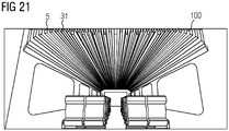
- each decorative profile 5 can be moved independently of the other decorative profiles 5, a wide variety of other geometric shapes of the ceiling element 100 can also be implemented (see also FIG Figures 20 and 21 ).
- a diffusing plate 7 is also provided here, which diffusely diffuses the light emitted by the LEDs 4.
- the spreading plate 7 is clamped between two decorative profiles 5 in each case.
- the legs of the decorative profiles 5 have grooves 51 on their outer sides, into which the scattering plate 7 is inserted.
- the diffusion plate 7 each covers a plurality of second receiving profiles 32 with LEDs 4 arranged therein.
- Embodiments are also possible in which the scattering plate 7 each covers a plurality of first 31 and second 32 receiving profiles.
- the associated decorative profiles 5 are pushed in further in the direction of the carrier 1, so that the scattering plate 7 also covers the corresponding decorative profiles 5 (see also FIG Figure 5 ).
- continuous strips of light can be used instead of a continuous light surface can be generated without perceiving individual LEDs 4 within the light strips.
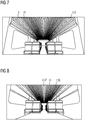
- FIG. 7 shows an embodiment of a rail vehicle with a ceiling element 100 mounted therein.
- the ceiling element 100 comprises only first receiving profiles 31 with associated decorative profiles 5.
- the ceiling element 100 forms the entire ceiling in an interior space of the rail vehicle.
- the decorative profiles 5 are set so that the ceiling is concave.
- FIG 8 Another exemplary embodiment of a rail vehicle is shown, in which the ceiling element 100 additionally has second receiving profiles 32 with LEDs 4 arranged therein.
- the LEDs 4 illuminate the interior of the rail vehicle during operation, in particular the central aisle and the area above the passenger seats. This creates a very homogeneous light distribution in the passenger compartment.
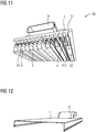
- Figure 10 and 11 show further exemplary embodiments of a ceiling element 100 in different views.
- an air duct 8 which is formed by a tube, is additionally provided on a side of the carrier 1 facing away from the receiving profiles 31, 32.
- the air duct 8 is supplied with cold air or warm air during operation, for example from an air conditioning system.
- the air duct 8 is fluidically connected via branch ducts 81, which are also formed by pipes, to selected ducts 6 which are formed by the decorative profiles 5 and the respective associated first receiving profiles 31.
- openings 310 are provided in the selected first receiving profiles 31, via which the branch channels 81 with the channels 6 are connected.
- the decorative profiles 5 have holes or perforations 50 through which the air fed into the channels 6 by the air channel 8 can escape into the environment.
- the size or volume of the relaxation space created by the channels 6 can be varied and the outflow speed of the air through the holes 50 can be regulated. This enables the air conditioning to be optimized in an interior of a rail vehicle in which such a ceiling element 100 is installed.
- the carrier 1 is a downwardly open half-shell, which is pierced at one point by the air duct 8, so that air supplied via the air duct 8 penetrates the half-shell and is distributed there.
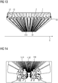
- FIG. 13 is the carrier 1 of the Figure 12 shown, wherein now additionally spacers 2 are attached to the inside of the carrier 1 designed as a half-shell and on these spacers 2 in turn receiving profiles 31, 32 are arranged.
- First receiving profiles 31, to which the decorative profiles 5 will later be applied, are each provided here with openings 310 through which the air supplied by the air channel 8 can flow into the channels 6.
- a sealing rubber 12 is provided on each of the ends of the legs of the first receiving profiles 31 facing away from the carrier 1.
- Such rubber seals 12 are preferably also present in the exemplary embodiment in FIGS. 10 and 11.
- the entire air duct chamber which is formed by the half-shell of the carrier 1 and the receiving profiles 31, 32 mounted on spacers 2, at the ends of which are hermetically sealed by a flexible material.
- Figure 14 shows again an interior of a rail vehicle with a ceiling element 100 built into it.
- the LEDs 4 of the ceiling element 100 are controlled here in such a way that a recommended route in the rail vehicle is signaled to a passenger by means of arrows. For example, a route to a less crowded interior / wagon of the rail vehicle is shown.
- These arrow signals can also be animated as running signals via a corresponding LED control.
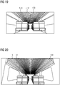
- the LEDs 4 of the ceiling element 4 are controlled so that they emit green light. This signals that the occupancy rate of the interior with passengers is low.
- the occupancy rate is slightly higher.
- the LEDs 4 are accordingly controlled in such a way that they emit yellow light, which signals an average degree of occupancy.
- the occupancy rate is high.
- the LEDs 4 are controlled in such a way that they emit red light, which signals a high degree of occupancy.
- the LEDs 4 of the ceiling element 100 are controlled in such a way that a logo is displayed to a passenger in the interior of the rail vehicle. This logo can also be animated as a running signal via a corresponding LED control.
- the LEDs 4 are controlled in such a way that a lettering is displayed to the passenger. This lettering too can be animated as a running signal via a corresponding LED control.
- Figures 20 and 21 show in addition to Figure 7 how the shape of the ceiling element 100 can be varied by moving the decorative profiles 5.
- special customer requests can be met in different vehicle platforms or in one and the same vehicle type and an individual spatial effect can be created via the ceiling shape, possibly in combination with a special light scenario.
Landscapes
- Engineering & Computer Science (AREA)
- Mechanical Engineering (AREA)
- Life Sciences & Earth Sciences (AREA)
- Wood Science & Technology (AREA)
- Arrangements Of Lighting Devices For Vehicle Interiors, Mounting And Supporting Thereof, Circuits Therefore (AREA)
- Connection Of Plates (AREA)
Abstract
Description
- Es wird ein Deckenelement für ein Schienenfahrzeug angegeben. Darüber hinaus wird ein Schienenfahrzeug angegeben. Weiterhin wird ein Verfahren zum Betreiben eines Deckenelements angegeben.
- Eine zu lösende Aufgabe besteht darin, ein Deckenelement für ein Schienenfahrzeug anzugeben, das in seiner geometrischen Form variiert werden kann. Weitere zu lösende Aufgaben bestehen darin, ein Schienenfahrzeug mit einem solchen Deckenelement und ein Verfahren zum Betreiben eines solchen Deckenelements anzugeben.
- Diese Aufgaben werden unter anderem durch die Gegenstände der Patentansprüche 1, 10 und 11 gelöst. Vorteilhafte Ausgestaltungen und Weiterbildungen sind Gegenstand der weiteren abhängigen Patentansprüche und gehen weiterhin aus der nachfolgenden Beschreibung und den Zeichnungen hervor.
- Zunächst wird das Deckenelement angegeben.
- Gemäß zumindest einer Ausführungsform umfasst das Deckenelement für ein Schienenfahrzeug einen Träger. Der Träger kann Kunststoff oder Metall, wie zum Beispiel Aluminium oder Edelstahl, aufweisen oder daraus bestehen. Der Träger ist zum Beispiel plattenförmig.
- Gemäß zumindest einer Ausführungsform weist das Deckenelement mehrere, auf einer Seite des Trägers angeordnete längliche Aufnahmeprofile auf. Die Aufnahmeprofile sind auf dem Träger fest und dauerhaft befestigt. Insbesondere sind die Aufnahmeprofile auf einem ebenen Abschnitt des Trägers angeordnet. Dieser Abschnitt ist beispielsweise mindestens so lang ist wie die Aufnahmeprofile. Dieser Abschnitt weist zum Beispiel eine Fläche von zumindest 1 m2 oder zumindest 5 m2 auf.
- Die Aufnahmeprofile sind bevorzugt im Rahmen der Herstellungstoleranz alle identisch ausgebildet, bestehen also aus dem gleichen Material und weisen die gleichen Abmessungen und die gleiche Form auf. Beispielsweise weisen die Aufnahmeprofile Kunststoff oder Metall, wie Aluminium oder Edelstahl, auf oder bestehen daraus.
- Ein Profil, auch Konstruktionsprofil genannt, ist ein langgestrecktes Bauteil, das insbesondere durch ein Extrusionsverfahren beziehungsweise Stangenpressverfahren oder aber auch durch Rollen oder Biegen von Blechteilen hergestellt ist. Die Aufnahmeprofile sind insbesondere um ein Vielfaches länger als breit und hoch. Beispielsweise betragen die Breiten der Aufnahmeprofile, gemessen parallel zur Haupterstreckungsebene des Trägers, zwischen einschließlich 10 mm und einschließlich 80 mm. Höhen der Aufnahmeprofile, gemessen senkrecht zur Haupterstreckungsebene des Trägers, betragen beispielsweise zwischen einschließlich 20 mm und einschließlich 120 mm. Längen der Aufnahmeprofile, gemessen entlang der Längsrichtung der Aufnahmeprofile und parallel zur Haupterstreckungsebene des Trägers betragen beispielsweise zumindest 50 cm oder zumindest 1 m.
- Die Aufnahmeprofile sind bevorzugt auf Abstandshaltern angeordnet, so dass sie nicht direkt auf dem Träger aufliegen, sondern von dem Träger durch die Abstandshalter beabstandet sind. Die Abstandshalter können matrixartig oder rasterartig auf dem Träger verteilt sein. Die Abstandshalter können aus dem gleichen Material wie der Träger bestehen. Beispielsweise sind die Aufnahmeprofile durch die Abstandshalter zwischen einschließlich 10 mm und einschließlich 100 mm von dem Träger beabstandet. Die Abstandshalter sind zum Beispiel zylinderartig oder säulenartig ausgebildet. Bevorzugt befinden sich die Aufnahmeprofile alle auf gleicher Höhe bezüglich des Trägers und sind in dieser Höhe fest auf diesem montiert. Beispielsweise umfasst das Deckenelement zumindest fünf oder zumindest zehn oder zumindest 20 Aufnahmeprofile.
- Gemäß zumindest einer Ausführungsform sind die Aufnahmeprofile in einer Querrichtung nebeneinander angeordnet und erstrecken sich jeweils entlang einer senkrecht zur Querrichtung verlaufenden Längsrichtung. Die Querrichtung und die Längsrichtung sind dabei Richtungen parallel zur Haupterstreckungsebene des Trägers. Die Breiten der Aufnahmeprofile sind parallel zur Querrichtung gemessen, die Längen der Aufnahmeprofile sind parallel zur Längsrichtung gemessen.
- Die Aufnahmeprofile sind in Querrichtung bevorzugt in gleichmäßigen Abständen angeordnet. Die Abstände zwischen zwei benachbarten Aufnahmeprofilen, gemessen entlang der Querrichtung, sind bevorzugt kleiner als die Breiten der Aufnahmeprofile, beispielsweise höchstens die Hälfte oder höchstens 1/5 der Breite.
- Gemäß zumindest einer Ausführungsform ist ersten Aufnahmeprofilen jeweils ein längliches Zierprofil zugeordnet. Ein einem ersten Aufnahmeprofil zugeordnetes Zierprofil ist dabei auf diesem ersten Aufnahmeprofil angeordnet. Als erste Aufnahmeprofile werden hier und im Folgenden also solche Aufnahmeprofile bezeichnet, denen ein Zierprofil zugeordnet ist, das heißt auf denen ein Zierprofil angeordnet ist. Jedem ersten Aufnahmeprofil kann ein eigenes Zierprofil eineindeutig zugeordnet sein oder es kann mehreren nebeneinanderliegenden ersten Aufnahmeprofilen ein gemeinsames Zielprofil zugeordnet sein. Entsprechend ist jedem Zierprofil zumindest ein erstes Aufnahmeprofil zugeordnet. Die Zierprofile sind auf den dem Träger abgewandten Seiten der zugeordneten ersten Aufnahmeprofile angeordnet.
- Die Zierprofile umfassen beispielsweise Kunststoff oder Metall, wie Aluminium, oder bestehen daraus. Die Zierprofile sind bevorzugt aus einem lichtundurchlässigen oder lichtreflektierenden Material. Die Längen der Zierprofile sind beispielsweise so groß wie die der Aufnahmeprofile. Insbesondere überlappen die Zierprofile mit den zugeordneten ersten Aufnahmeprofilen entlang der Längsrichtung vollständig. Breiten und Höhen der Zierprofile sind insbesondere so gewählt, dass die Zierprofile über oder in die ersten Aufnahmeprofile geschoben werden können. Die Höhen der Zierprofile sind beispielsweise größer als die der Aufnahmeprofile.
- Gemäß zumindest einer Ausführungsform sind die Zierprofile an den ersten Aufnahmeprofilen verschiebbar befestigt, sodass sich die Zierprofile bezüglich der ersten Aufnahmeprofile in Richtung hin und/oder weg von dem Träger verschieben lassen. Mit anderen Worten sind die Zierprofile und die ersten Aufnahmeprofile ineinander oder übereinander geschoben und miteinander stabil verbunden, wobei sich jedoch der Abstand der Zierprofile zum Träger variieren lässt. Jedes Zierprofil lässt sich dabei bevorzugt einzeln unabhängig von den anderen Zierprofilen in Richtung hin zur oder weg von dem Träger verschieben. Zum Beispiel kann der Abstand zwischen den Zierprofilen und dem Träger jeweils um mindestens 1 cm oder mindestens 5 cm oder mindestens 10 cm variiert werden. In mindestens einer Ausführungsform umfasst das Deckenelement für ein Schienenfahrzeug einen Träger und mehrere auf einer Seite des Trägers angeordnete längliche Aufnahmeprofile. Die Aufnahmeprofile sind in einer Querrichtung nebeneinander angeordnet und erstrecken sich jeweils entlang einer senkrecht zur Querrichtung verlaufenden Längsrichtung. Ersten Aufnahmeprofilen ist jeweils ein längliches Zierprofil zugeordnet, wobei ein einem ersten Aufnahmeprofil zugeordnetes Zierprofil auf diesem ersten Aufnahmeprofil angeordnet ist. Die Zierprofile sind an den ersten Aufnahmeprofilen verschiebbar befestigt, sodass sich die Zierprofile bezüglich der ersten Aufnahmeprofile in Richtung hin und/oder weg von dem Träger verschieben lassen.
- Wird ein solches Deckenelement als Decke oder Deckenabschnitt in einem Schienenfahrzeug verwendet, kann die Form der Decke durch Verschieben der Zierprofile variiert werden. Das Deckenelement kann so bei einer Vielzahl von verschiedenen Schienenfahrzeugen eingesetzt werden, um unterschiedliche Raumwirkungen gemäß Kundenwunsch zu generieren, ohne dabei jedes Mal den Aufbau des Deckenelements verändern zu müssen.
- Gemäß zumindest einer Ausführungsform sind in zweiten Aufnahmeprofilen jeweils mehrere, in Längsrichtung hintereinander aufgereihte LEDs (Leuchtdioden) angeordnet. Als zweite Aufnahmeprofile werden hier und im Folgenden solche Aufnahmeprofile bezeichnet, in denen LEDs angeordnet sind. Auf zweiten Aufnahmeprofilen sind bevorzugt keine Zierprofile angeordnet. Andersherum sind in ersten Aufnahmeprofilen bevorzugt keine LEDs angeordnet.
- Beispielsweise sind in jedem zweiten Aufnahmeprofil zumindest zehn oder zumindest 50 LEDs angeordnet. In jedem der zweiten Aufnahmeprofile kann ein LED-Band, umfassend eine flexible Leiterplatte und eine Vielzahl von hintereinander aufgereihten LEDs, angeordnet sein. Die LEDs emittieren im Betrieb bevorzugt sichtbares Licht. Bevorzugt ist jedes Aufnahmeprofil des Deckenelements entweder ein erstes oder ein zweites Aufnahmeprofil.
- Gemäß zumindest einer Ausführungsform überragen die Zierprofile die LEDs in Richtung weg von dem Träger. Beispielsweise überragen die Zierprofile die LEDs um zumindest 10 mm oder zumindest 20 mm. Licht, welches von den LEDs im Betrieb abgestrahlt wird, trifft dann bevorzugt auf Seitenflächen der Zierprofile und wird von diesen reflektiert. Die LEDs liegen also vertieft und bei Verwendung des Deckenelements in einem Schienenfahrzeug werden daher seitlich sitzende Fahrgäste bevorzugt nicht geblendet.
- Gemäß zumindest einer Ausführungsform ist die verschiebbare Befestigung der Zierprofile an den ersten Aufnahmeprofilen durch eine Ratschenfunktion und/oder ein Schraubengewinde und/oder höhenverstellbaren Magneten realisiert. Bei einer Ratschenfunktion sind die Aufnahmeprofile und die Zierprofile beispielsweise gezahnt, wobei die Zähne ineinandergreifen. Das Deckenelement kann einen Schrittmotor umfassen, der dazu eingerichtet ist, die Zierprofile bezüglich der ersten Aufnahmeprofile zu verschieben. Auf diese Weise kann ein Verschieben der Aufnahmeprofile automatisiert erfolgen.
- Gemäß zumindest einer Ausführungsform sind die Aufnahmeprofile und die Zierprofile U-Profile. Das heißt, in Querschnittsansicht haben die Aufnahmeprofile und die Zierprofile eine U-förmige Form. Mit anderen Worten weisen die Aufnahmeprofile und die Zierprofile jeweils einen langgestreckten Mittelabschnitt und in Querrichtung beidseitig des Mittelabschnitts angeordnete langgestreckte Schenkel auf, die sich ausgehend von dem Mittelabschnitt weg von dem Mittelabschnitt erstrecken. An Seiten der Profile gegenüber dem Mittelabschnitt sind die Profile jeweils offen.
- Die Aufnahmeprofile und die Zierprofile sind beispielsweise so auf dem Träger angeordnet, dass die Haupterstreckungsebenen der Mittelabschnitte jeweils parallel zur Haupterstreckungsebene des Trägers und die Haupterstreckungsebenen der Schenkel jeweils quer oder senkrecht zur Haupterstreckungsebene des Trägers verlaufen. Die Aufnahmeprofile sind insbesondere so auf dem Träger aufgebracht, dass die Mittelabschnitte dem Träger zugewandt sind und die Schenkel sich ausgehend von dem Mittelabschnitt in Richtung weg von dem Träger erstrecken. Die LEDs sind bevorzugt auf den Mittelabschnitten der zweiten Aufnahmeprofile angeordnet. Das von den LEDs im Betrieb emittierte Licht kann dann über die offene Seite der zweiten Aufnahmeprofile austreten.
- Gemäß zumindest einer Ausführungsform sind die Zierprofile derart auf den ersten Aufnahmeprofilen angeordnet, dass zwischen den ersten Aufnahmeprofilen und den zugeordneten Zierprofilen jeweils ein Kanal, insbesondere ein röhrenförmiger Kanal, gebildet ist. Dafür sind insbesondere die Zierprofile und die ersten Aufnahmeprofile mit ihren offenen Seiten einander zugewandt aufeinander angeordnet beziehungsweise ineinander oderübereinander geschoben. Mit anderen Worten sind die Zierprofile auf den ersten Aufnahmeprofilen derart angeordnet, dass die Schenkel der ersten Aufnahmeprofile und der Zierprofile zwischen den Mittelabschnitten der ersten Aufnahmeprofile und der Zierprofile liegen. Die dadurch gebildeten Kanäle sind in Richtungen senkrecht zur Längsrichtung vollständig von den Profilen umschlossen. Die Kanäle erstrecken sich jeweils bevorzugt über die gesamte Länge des ersten Aufnahmeprofils beziehungsweise Zierprofils.
- Durch die Wahl von U-Profilen können die Zierprofile und die ersten Aufnahmeprofile derart ineinander geschoben werden, dass die Schenkel der Zierprofile die Schenkel der ersten Aufnahmeprofile umklammern oder umgekehrt. Bevorzugt liegen die Schenkel der Zierprofile und der zugeordneten ersten Aufnahmeprofile dann unmittelbar aufeinander auf. Beim Verschieben der Zierprofile werden die Schenkel der Zierprofile innerhalb der Bereiche zwischen zwei benachbarten Aufnahmeprofilen geführt. Der Abstand zwischen je zwei benachbarten Aufnahmeprofilen ist dann bevorzugt im Bereich der Stärke der Schenkel des Zierprofils. Zum Beispiel ist der Abstand höchstens doppelt so groß oder höchstens 1,5-mal so groß wie die Stärke der Schenkel.
- Gemäß zumindest einer Ausführungsform sind die ersten Aufnahmeprofile und die zweiten Aufnahmeprofile in Querrichtung alternierend angeordnet. Das heißt, zwischen je zwei Aufnahmeprofilen mit jeweils einem zugeordneten Zierprofil ist ein Aufnahmeprofil mit jeweils LEDs angeordnet und umgekehrt.
- Alternativ ist es aber auch möglich, dass zwischen zwei ersten Aufnahmeprofilen mehrere, zum Beispiel zumindest drei oder zumindest fünf, oder zumindest zehn zweite Aufnahmeprofile aber kein weiteres erstes Aufnahmeprofil angeordnet sind. Bei einer solchen Anordnung können beispielsweise mithilfe der LEDs dieser zweiten Aufnahmeprofile zweidimensionale Bilder, Piktogramme oder Symbole dargestellt werden. In diesem Fall sind beispielsweise die zweiten Aufnahmeprofile schmäler als die ersten Aufnahmeprofile gewählt, um eine höhere Pixeldichte zu erreichen.
Gemäß zumindest einer Ausführungsform weist das Deckenelement eine Streuplatte zur Streuung der von den LEDs emittierten Strahlung auf. Die Streuplatte ist beispielsweise aus transluzentem Kunststoff gebildet. Die Streuplatte streut die von den LEDs emittierte Strahlung beispielsweise diffus. - Gemäß zumindest einer Ausführungsform ist die Streuplatte zwischen zwei Zierprofilen eingespannt. Beispielsweise umfassen dazu die Schenkel der Zierprofile an Außenseiten Nuten, in die die Streuplatte eingeführt ist.
- Gemäß zumindest einer Ausführungsform sind ein oder mehrere zweite Aufnahmeprofile mit LEDs zwischen der Streuplatte und dem Träger angeordnet. Das heißt, in einer Draufsicht betrachtet überdeckt die Streuplatte ein oder mehrere zweite Aufnahmeprofile und die darin angeordneten LEDs. Im eingebauten Zustand des Deckenelements sind für einen Passagier im Schienenfahrzeug die einzelnen LEDs aufgrund der Streuung durch die Streuplatte dann bevorzugt nicht mehr als separate Lichtpunkte, sondern als homogene Lichtfläche wahrnehmbar. Es können auch mehrere solcher Streuplatten in dem Deckenelement angeordnet sein, zum Beispiel in der Mitte und zusätzlich an den Randzonen des Deckenelements. Dadurch kann erreicht werden, dass eine gleichmäßige und ausreichende Lichtverteilung, sowohl im Gangbereich, als auch über den Fahrgast-Sitzplätzen gewährleistet wird.
- Gemäß zumindest einer Ausführungsform umfasst das Deckenelement weiter einen Luftkanal an einer den Aufnahmeprofilen abgewandten Seite des Trägers. Der Luftkanal, oder auch Luftschacht genannt, ist zur Zuführung von Kaltluft oder Warmluft vorgesehen. Im eingebauten Zustand des Deckenelements sind die Aufnahmeprofile einem Innenraum des Schienenfahrzeugs zugewandt und der Luftkanal ist dem Innenraum abgewandt. Der Luftkanal kann im eingebauten Zustand mit einer Klimaanlage verbunden sein, die Kaltluft oder Warmluft in den Luftkanal einspeist. Der Luftkanal ist durch ein Rohr, zum Beispiel aus Metall, gebildet.
- Gemäß zumindest einer Ausführungsform sind zumindest einige Kanäle über Öffnungen in den den Kanälen zugeordneten ersten Aufnahmeprofilen fluidtechnisch mit dem Luftkanal verbunden, sodass über den Luftkanal zugeführte Luft über die Öffnungen in die Kanäle einströmen kann. Beispielsweise sind ausgehend von dem Luftkanal Stichkanäle durch den Träger zu den ersten Aufnahmeprofilen geführt, wobei die Stichkanäle über die Öffnung in den ersten Aufnahmeprofilen mit den Kanälen zwischen den ersten Aufnahmeprofilen und den Zierprofilen fluidtechnisch verbunden sind. Die Öffnungen in den ersten Aufnahmeprofilen sind bevorzugt in den Mittelabschnitten der ersten Aufnahmeprofile gebildet.
- Gemäß zumindest einer Ausführungsform weisen die den ersten Aufnahmeprofilen mit Öffnungen zugeordneten Zierprofile Löcher beziehungsweise eine Perforierung, insbesondere eine gleichmäßige Perforierung auf, aus denen die Luft in den Kanälen in die Umgebung ausströmen, insbesondere in den Fahrgastraum strömen kann. Die Löcher beziehungsweise die Perforierung sind beispielsweise in dem Mittelabschnitt und/oder den Schenkeln der Zierprofile angeordnet.
- Durch die Löcher in den Zierprofilen wird die in die Kanäle eingespeiste Luft an ausgewählte Stellen in die Umgebung abgegeben und kann dann zur gezielten Kühlung oder Erwärmung eines Innenraums eines Schienenfahrzeuges dienen. Dadurch dass die Zierprofile bezüglich der ersten Aufnahmeprofile verschiebbar sind, kann das Volumen der Kanäle zwischen den Zierprofilen und den ersten Aufnahmeprofilen variiert werden. Das heißt, die Größe des Entspannungsraum für die in die Kanäle eingespeiste Luft, der sich durch das Volumen der oben genannten Kanäle definiert, kann verändert und damit die Austrittsgeschwindigkeit der Luft durch die Löcher geregelt werden. Löcher in den Schenkeln der Zierprofile können zudem vorteilhaft zur Kühlung der LEDs in benachbarten zweiten Aufnahmeprofilen dienen.
- Die Kanäle, die über die Öffnungen in den ersten Aufnahmeprofilen fluidtechnisch mit dem Luftkanal verbunden sind, können an den längsseitigen Enden durch eine flexible Abdeckung, beispielsweise durch eine Gummihaut, abgedichtet sein, sodass an den Enden keine Luft austritt auch, wenn durch Verschieben der Zierprofile der Kanalquerschnitt und damit auch der Abdeckungsquerschnitt verändert wird.
- Gemäß zumindest einer Ausführungsform umfasst das Deckenelement eine Steuereinheit. Die Steuereinheit ist signaltechnisch mit den LEDs verbunden und dazu eingerichtet, die LEDs oder verschiedene Gruppen von LEDs einzeln und unabhängig anzusteuern. Die Steuereinheit ist beispielsweise auf der den Aufnahmeprofilen abgewandten Seite des Trägers angeordnet.
- Zum Beispiel umfasst das Deckenelement verschiedenfarbige LEDs, wobei mit der Steuereinheit verschiedenfarbige LEDs individuell ansteuerbar sind, sodass die von dem Deckenelement emittierte Lichtfarbe variiert werden kann.
- Als nächstes wird das Schienenfahrzeug angegeben. Das Schienenfahrzeug weist ein hier beschriebenes Deckenelement auf. Das Deckenelement bildet insbesondere eine Decke oder einen Abschnitt einer Decke in einem Innenraum des Schienenfahrzeuges, insbesondere in einem Aufenthaltsraum oder Abteil für Fahrgäste. Das Deckenelement ist dabei insbesondere so in dem Schienenfahrzeug montiert, dass die Seite des Trägers mit den Aufnahmeprofilen dem Innenraum zugewandt ist. Die LEDs beleuchten im bestimmungsgemäßen Betrieb den Innenraum des Schienenfahrzeuges.
- Als nächstes wird das Verfahren zum Betreiben eines Deckenelements angegeben. Während des Verfahrens ist das Deckenelement in einem Innenraum eines Schienenfahrzeugs verbaut. Die LEDs werden in Abhängigkeit davon, wie viele Fahrgäste im Innenraum des Schienenfahrzeugs sind, angesteuert. Alternativ oder zusätzlich werden die LEDs so angesteuert, dass sie einem Fahrgast einen empfohlenen Weg im Schienenfahrzeug signalisieren. Alternativ oder zusätzlich werden die LEDs so angesteuert, dass Bilder oder Piktogramme dargestellt werden. Das Ansteuern der LEDs erfolgt insbesondere mithilfe der Steuereinheit.
- Umfasst das Deckenelement verschiedenfarbige LEDs, sind zum Beispiel unterschiedlichen Belegungsgraden des Innenraums mit Fahrgästen unterschiedliche Farben zugeordnet. Zum Beispiel wird einem niedrigen Belegungsgrad die Farbe Grün, einem mittleren Belegungsgrad die Farbe Gelb oder Orange und einem hohen Belegungsgrad die Farbe Rot zugeordnet. Im Betrieb werden dann die LEDs so angesteuert, dass das Deckenelement Licht mit einer Farbe emittiert, die dem aktuellen Belegungsgrad zugeordnete ist. So kann ein Fahrgast beim Betreten des Innenraums sofort erkennen, ob er einen Platz bekommen wird oder ob er lieber in einen anderen Innenraum/anderen Waggon des Schienenfahrzeuges geht. "Belegungsrad" meint hier die Dichte oder Anzahl an Fahrgästen im Innenraum.
- Die LEDs können alternativ oder zusätzlich so angesteuert werden, dass sie einem Fahrgast einen empfohlenen Weg im Schienenfahrzeug signalisieren. Beispielsweise werden dabei die LEDs so angesteuert, dass an dem Deckenelement Pfeile dargestellt werden, die für einen Fahrgast im Innenraum sichtbar sind. Die Pfeile können beispielsweise einen Weg zu einem weniger belegten Waggon andeuten.
- Um dies zu realisieren, umfasst das Schienenfahrzeug beispielsweise ein System, das signaltechnisch mit Sensoren aus den verschiedenen Innenräumen beziehungsweise Waggons verbunden ist. Die Sensoren sind zum Beispiel Kameras und/oder Gewichtssensoren in Sitzen, mit denen der Belegungsgrad in dem Innenraum ermittelbar ist. Das System ist zum Beispiel dazu eingerichtet, die Belegungsgrade in den unterschiedlichen Innenräumen miteinander zu vergleichen und beispielsweise ein Belegungsgradgefälle entlang des Schienenfahrzeuges zu ermitteln. In Abhängigkeit von dem Vergleich oder dem Belegungsgradgefälle steuert dann die Steuereinheit die Leuchte an, um den Weg zu einem weniger belegten Innenraum anzuzeigen.
- Die LEDs können beispielsweise auch so angesteuert werden, dass für den Fahrgast sichtbare Bilder oder Piktogramme an dem Deckenelement dargestellt werden. Zum Beispiel kann durch die LEDs an der Decke ein Logo oder ein Schriftzug dargestellt werden. Auch Laufbilder können realisiert werden. Bevorzugt liegen in diesem Fall mehrere zweite Aufnahmeprofile, jeweils mit mehreren LEDs, in Querrichtung nebeneinander, ohne dass zwischen ihnen ein erstes Aufnahmeprofil mit zugeordnetem Zierprofil angeordnet ist.
- Die oben genannten Eigenschaften, Merkmale und Vorteile der Erfindung und die Art und Weise, wie diese erreicht werden, werden durch die folgende Beschreibung der Ausführungsbeispiele der Erfindung in Verbindung mit den entsprechenden Figuren weitergehend erläutert, wobei
-
Figuren 1, 2 ,5, 6 ,10 und11 verschiedene Ausführungsbeispiele des Deckenelements in perspektivischer Ansicht zeigen, -
Figuren 3, 4 ,12 und13 Teile aus Ausführungsbeispielen des Deckenelements in perspektivischer Ansicht zeigen, -
Figuren 7, 8 ,9 ,14 und15 bis 21 jeweils ein Ausführungsbeispiel des Schienenfahrzeugs mit einem Deckenelement zeigen. -
Figur 1 zeigt ein erstes Ausführungsbeispiel eines Deckenelements 100 in perspektivischer Ansicht. Das Deckenelement 100 umfasst einen plattenförmigen Träger 1 und Abstandshalter 2 auf einer Seite des Trägers 1. Der Träger 1 und die Abstandshalter 2 sind separat nochmal inFigur 3 dargestellt. Der Träger 1 und die Abstandshalter 2 sind beispielsweise aus Aluminium gebildet. - Auf den Abstandshaltern 2 sind längliche Aufnahmeprofile 31, 32 montiert. Durch die Abstandshalter 2 sind die Aufnahmeprofile 31, 32 von dem Träger 1 beabstandet. Die Aufnahmeprofile 31, 32 sind beispielsweise aus Kunststoff oder Aluminium gebildet. In einer Querrichtung Q sind die Aufnahmeprofile 31, 32 nebeneinander angeordnet. Die Aufnahmeprofile 31, 32 erstrecken sich jeweils entlang einer Längsrichtung L. Insbesondere sind die Aufnahmeprofile 31, 32 also parallel zueinander angeordnet (siehe insbesondere auch
Figur 4 ). - Weiter ist in
Figur 1 zu sehen, dass auf ersten Aufnahmeprofilen 31 jeweils Zierprofile 5 angeordnet sind. Die Aufnahmeprofile 31, 32 und die Zierprofile 5 sind hier jeweils U-Profile. Die Zierprofile 5 sind derart auf die ersten Aufnahmeprofile 31 geschoben, dass zwischen den ersten Aufnahmeprofilen 31 und den Zierprofilen 5 jeweils ein Kanal 6 gebildet ist, der sich entlang der Längsrichtung L erstreckt und in Richtungen senkrecht zur Längsrichtung vollständig umschlossen ist. - In zweiten Aufnahmeprofilen 32 sind in Längsrichtung L hintereinander aufgereihte LEDs 4 angeordnet. Die LEDs 4 sind insbesondere Teil eines LED-Bandes, welches in die zweiten Aufnahmeprofile 32 eingebracht ist. Über die offenen Seiten der zweiten Aufnahmeprofile 32 kann das von den LEDs 4 emittierte Licht austreten.
- In der
Figur 1 wechseln sich erste Aufnahmeprofile 31 mit zugeordneten Zierprofilen 5 und zweite Aufnahmeprofile 32 mit zugeordneten LEDs 4 in Querrichtung Q ab. Die LEDs 4 emittieren im Betrieb beispielsweise sichtbares Licht. Auf einer den Aufnahmeprofilen 31, 32 gegenüberliegenden Seite des Trägers 1 ist eine Steuereinheit 9 angeordnet, die signaltechnisch mit den LEDs 4 verbunden ist. Die Steuereinheit 9 ist dazu eingerichtet, die LEDs 4 einzeln oder Gruppen von LEDs 4 einzeln und unabhängig voneinander anzusteuern. - Wie in den
Figuren 1 und 2 zu sehen ist, sind die Zierprofile 5 auf den zugeordneten ersten Aufnahmeprofilen 31 verschiebbar befestigt, so dass sich die Zierprofile 5 bezüglich der zugeordneten ersten Aufnahmeprofile 31 in Richtung hin und weg von dem Träger 1 verschieben lassen. Mit anderen Worten lassen sich die Abstände der Zierprofile 5 zu dem Träger 1 verändern. Folglich lassen sich auch die Volumina der zwischen den Zierprofilen 5 und den zugeordneten ersten Aufnahmeprofilen 31 gebildeten Kanäle 6 verändern. Die Verschiebbarkeit der Zierprofile 5 gegenüber den ersten Aufnahmeprofilen 31 ist vorliegend beispielsweise durch eine Ratschenfunktion realisiert. Dazu sind beispielsweise die Schenkel der ersten Aufnahmeprofile 31 und der zugeordneten Zierprofile 5, die in den Figuren aufeinander liegen, mit einer Zahnung versehen. - In den
Figuren 1 und 2 sind nur zwei mögliche Gestaltungen des Deckenelements 100 gezeigt. In derFigur 1 ist das mittlere Zierprofil 5 am weitesten in Richtung des Trägers 1 verschoben. Die weiter außenliegenden Zierprofile 5 sind weiter von dem Träger 1 weggezogen. Das Deckenelement 100 weist dadurch eine konkave Krümmung auf. In derFigur 2 hingegen ist das mittlere Zierprofil 5 am weitesten von dem Träger 1 weggezogen. Die weiter außenliegenden Zierprofile 5 sind näher an den Träger 1 geschoben. Das Deckenelement 100 weist eine konvexe Krümmung auf. - Da jedes Zierprofil 5 unabhängig von den anderen Zierprofilen 5 verschiebbar ist, sind auch verschiedenste weitere geometrische Formen des Deckenelements 100 realisierbar (siehe auch
Figuren 20 und21 ). - In den
Figuren 5 und 6 sind zwei weitere Ausführungsbeispiele des Deckenelements 100 dargestellt. Hier ist zusätzlich eine Streuplatte 7 vorhanden, die das von den LEDs 4 emittierte Licht diffus streut. Die Streuplatte 7 ist dabei jeweils zwischen zwei Zierprofilen 5 eingespannt. Dazu weisen die Schenkel der Zierprofile 5 an Außenseiten Nuten 51 auf, in die die Streuplatte 7 eingeschoben ist. Die Streuplatte 7 überdeckt jeweils eine Mehrzahl von zweiten Aufnahmeprofilen 32 mit darin angeordneten LEDs 4.
Es sind auch Ausführungsbeispiele möglich, bei denen die Streuplatte 7 jeweils eine Mehrzahl von ersten 31 und zweiten 32 Aufnahmeprofilen überdeckt. Bei den überdeckten ersten Aufnahmeprofilen 31 sind in diesem Fall die dazugehörigen Zierprofile 5 weiter in Richtung Träger 1 eingeschobenen, sodass die Streuplatte 7 auch die entsprechenden Zierprofile 5 überdeckt (siehe auchFigur 5 ). Auf diese Weise können statt einer durchgängigen Lichtfläche durchgängige Lichtstreifen generiert werden, ohne dass man einzelne LEDs 4 innerhalb der Lichtstreifen wahrnimmt. - In der
Figur 7 ist ein Ausführungsbeispiel eines Schienenfahrzeuges mit einem darin montierten Deckenelement 100 gezeigt. Vorliegend umfasst das Deckenelement 100 nur erste Aufnahmeprofile 31 mit zugeordneten Zierprofilen 5. Das Deckenelement 100 bildet die gesamte Decke in einem Innenraum des Schienenfahrzeuges. Die Zierprofile 5 sind so eingestellt, dass die Decke konkav gekrümmt ist. - In der
Figur 8 ist ein weiteres Ausführungsbeispiel eines Schienenfahrzeuges gezeigt, bei dem das Deckenelement 100 zusätzlich zweite Aufnahmeprofile 32 mit darin angeordneten LEDs 4 aufweist. Die LEDs 4 beleuchten im Betrieb den Innenraum des Schienenfahrzeugs und zwar insbesondere den Mittelgang und den Bereich über den Fahrgastsitzen. Dadurch wird eine sehr homogene Lichtverteilung im Fahrgastraum erzeugt. - In der
Figur 9 ist der Innenraum des Schienenfahrzeuges ausFigur 8 in einer Querschnittsansicht gezeigt. -
Figur 10 und11 zeigen weitere Ausführungsbeispiele eines Deckenelements 100 in unterschiedlichen Ansichten. Hier ist zusätzlich auf einer den Aufnahmeprofilen 31, 32 abgewandten Seite des Trägers 1 ein Luftkanal 8, der durch ein Rohr gebildet ist, vorgesehen. Dem Luftkanal 8 wird im Betrieb kalte Luft oder warme Luft zugeführt, beispielsweise von einer Klimaanlage. Der Luftkanal 8 ist über Stichkanäle 81, welche ebenfalls durch Rohre gebildet sind, fluidtechnisch mit ausgewählten Kanälen 6 verbunden, die von den Zierprofilen 5 und jeweils dazugehörigen ersten Aufnahmeprofilen 31 gebildet werden. Dazu sind in den ausgewählten ersten Aufnahmeprofilen 31 Öffnungen 310 vorgesehen, über die die Stichkanäle 81 mit den Kanälen 6 verbunden sind. Außerdem weisen die Zierprofile 5 Löcher beziehungsweise Perforierungen 50 auf, über die die von dem Luftkanal 8 in die Kanäle 6 eingespeiste Luft in die Umgebung entweichen kann. - Durch die Verstellbarkeit des Abstandes der Zierprofile 5 zum Träger 1 kann die Größe beziehungsweise das Volumen des Entspannungsraumes, der durch die Kanäle 6 erzeugt wird, variiert werden und so die Ausströmgeschwindigkeit der Luft durch die Löcher 50 geregelt werden. Dies ermöglicht eine Optimierung der Klimatisierung in einem Innenraum eines Schienenfahrzeuges, in dem ein solches Deckenelement 100 verbaut ist.
- In der
Figur 12 ist ein zweites Ausführungsbeispiel für den Luftkanal 8 gezeigt. Der Träger 1 ist eine nach unten offene Halbschale, die an einer Stelle von dem Luftkanal 8 durchstoßen ist, sodass über den Luftkanal 8 zugeführte Luft in die Halbschale eindringt und sich dort verteilt. - In der
Figur 13 ist der Träger 1 derFigur 12 gezeigt, wobei nun zusätzlich Abstandshalter 2 auf der Innenseite des als Halbschale ausgeführten Trägers 1 angebracht sind und auf diesen Abstandshaltern 2 wiederum Aufnahmeprofile 31, 32 angeordnet sind. Erste Aufnahmeprofile 31, auf die später die Zierprofile 5 aufgebracht werden, sind hier jeweils mit Öffnungen 310 versehen, über die die von dem Luftkanal 8 zugeführte Luft in die Kanäle 6 einströmen kann. Um die Kanäle 6 am Übergang zwischen den Zierprofilen 5 und den ersten Aufnahmeprofilen 31 luftdicht abzudichten, ist auf den dem Träger 1 abgewandten Enden der Schenkel der ersten Aufnahmeprofile 31 jeweils ein Dichtgummi 12 vorgesehen. Solche Dichtgummis 12 sind bevorzugt auch im Ausführungsbeispiel der Figuren 10 und 11 vorhanden. Zudem kann die komplette Luftkanalkammer, die gebildet wird durch die Halbschale des Trägers 1 und den auf Abstandhaltern 2 montierten Aufnahmeprofilen 31,32, an deren Enden luftdicht über ein flexibles Material abgeschlossen sein. -
Figur 14 zeigt wieder einen Innenraum eines Schienenfahrzeuges mit einem darin eingebauten Deckenelement 100. Die LEDs 4 des Deckenelements 100 werden hier so angesteuert, dass einem Fahrgast ein empfohlener Weg im Schienenfahrzeug anhand von Pfeilen signalisiert wird. Beispielsweise wird ein Weg zu einem weniger vollen Innenraum/Waggon des Schienenfahrzeuges gezeigt. Diese Pfeilsignale können über eine entsprechende LED-Ansteuerung auch als Laufsignal animiert werden. - In der
Figur 15 werden die LEDs 4 des Deckenelements 4 so angesteuert, dass sie grünes Licht emittieren. Dies signalisiert, dass der Belegungsgrad des Innenraums mit Fahrgästen gering ist. - In der
Figur 16 ist der Belegungsgrad etwas höher. Entsprechend werden die LEDs 4 so angesteuert, dass sie gelbes Licht emittieren, was einen mittleren Belegungsgrad signalisiert. - In der
Figur 17 ist der Belegungsgrad hoch. Die LEDs 4 werden so angesteuert, dass sie rotes Licht emittieren, was einen hohen Belegungsgrad signalisiert. - In der
Figur 18 werden die LEDs 4 des Deckenelements 100 so angesteuert, dass einem Fahrgast in dem Innenraum des Schienenfahrzeuges ein Logo angezeigt wird. Auch dieses Logo kann über eine entsprechende LED-Ansteuerung als Laufsignal animiert werden. - In der
Figur 19 werden die LEDs 4 so angesteuert, dass dem Fahrgast ein Schriftzug angezeigt wird. Auch dieser Schriftzug kann über eine entsprechende LED-Ansteuerung als Laufsignal animiert werden. - Die
Figuren 20 und21 zeigen ergänzend zuFigur 7 , wie die Form des Deckenelements 100 durch Verschieben der Zierprofile 5 variiert werden kann. Auf diese Weise kann in verschiedenen Fahrzeugplattformen oder in ein und demselben Fahrzeugtyp auf spezielle Kundenwünsche eingegangen werden und über die Deckenform, gegebenenfalls in Kombination mit einem speziellen Lichtszenario, eine individuelle Raumwirkung erzeugt werden. - Obwohl die Erfindung anhand von Ausführungsbeispielen detailliert dargestellt und beschrieben wurde, ist die Erfindung nicht auf die offenbarten Ausführungsbeispiele und die darin erläuterten konkreten Merkmalskombinationen beschränkt. Weitere Variationen der Erfindung können von einem Fachmann erhalten werden, ohne den Schutzumfang der beanspruchten Erfindung zu verlassen.
Claims (11)
- Deckenelement (100) für ein Schienenfahrzeug, umfassend- einen Träger (1),- mehrere, auf einer Seite des Trägers (1) angeordnete längliche Aufnahmeprofile (31, 32), wobei- die Aufnahmeprofile (31, 32) in einer Querrichtung (Q) nebeneinander angeordnet sind und sich jeweils entlang einer senkrecht zur Querrichtung (Q) verlaufenden Längsrichtung (L) erstrecken,- ersten Aufnahmeprofilen (31) jeweils ein längliches Zierprofil (5) zugeordnet ist, wobei ein einem ersten Aufnahmeprofil (31) zugeordnetes Zierprofil (5) auf diesem ersten Aufnahmeprofil (31) angeordnet ist,- die Zierprofile (5) an den ersten Aufnahmeprofilen (31) verschiebbar befestigt sind, sodass sich die Zierprofile (5) bezüglich der ersten Aufnahmeprofile (31) in Richtung hin und/oder weg von dem Träger (1) verschieben lassen.
- Deckenelement (100) nach Anspruch 1, wobei- in zweiten Aufnahmeprofilen (32) jeweils mehrere, in Längsrichtung (L) hintereinander aufgereihte LEDs (4) angeordnet sind,- die Zierprofile (5) die LEDs (4) in Richtung weg von dem Träger (1) überragen.
- Deckenelement (100) nach Anspruch 1 oder 2,
wobei die verschiebbare Befestigung der Zierprofile (5) an den ersten Aufnahmeprofilen (31) durch eine Ratschenfunktion und/oder ein Schraubengewinde und/oder höhenverstellbare Magnete realisiert ist. - Deckenelement (100) nach einem der vorhergehenden Ansprüche, wobei- die Aufnahmeprofile (31, 32) und die Zierprofile (5) U-Profile sind,- die Zierprofile (5) derart auf den ersten Aufnahmeprofilen (31) angeordnet sind, dass zwischen den ersten Aufnahmeprofilen (31) und den zugeordneten Zierprofilen (5) jeweils ein Kanal (6) gebildet ist.
- Deckenelement (100) nach Anspruch 2 oder nach einem der Ansprüche 3 bis 4 in ihrem jeweiligen Rückbezug auf Anspruch 2,
wobei die ersten Aufnahmeprofile (31) und die zweiten Aufnahmeprofile (32) in Querrichtung (Q) alternierend angeordnet sind. - Deckenelement (100) nach Anspruch 2 oder nach einem der Ansprüche 3 bis 5 in ihrem jeweiligen Rückbezug auf Anspruch 2, weiter aufweisend- eine Streuplatte (7) zur Streuung der von den LEDs (4) emittierten Strahlung,- die Streuplatte (7) zwischen zwei Zierprofilen (5) eingespannt ist,- ein oder mehrere zweite Aufnahmeprofile (32) mit LEDs (4) zwischen der Streuplatte (7) und dem Träger (1) angeordnet sind.
- Deckenelement (100) nach Anspruch 4 oder einem der Ansprüche 5 bis 6 in ihrem Rückbezug auf Anspruch 4, weiter umfassend- einen Luftkanal (8) an einer den Aufnahmeprofilen (31, 32) abgewandten Seite des Trägers (1), wobei- zumindest einige Kanäle (6) über Öffnungen (310) in den zugeordneten ersten Aufnahmeprofilen (31) fluidtechnisch mit dem Luftkanal (8) verbunden sind, sodass über den Luftkanal (8) zugeführte Luft über die Öffnungen (310) in die Kanäle (6) einströmen kann.
- Deckenelement (100) nach Anspruch 7,
wobei die den ersten Aufnahmeprofilen (31) mit Öffnungen (310) zugeordneten Zierprofile (5) Löcher(50) aufweisen, aus denen die Luft in die Umgebung ausströmen kann. - Deckenelement (100) nach Anspruch 2 oder einem der Ansprüche 3 bis 8 in ihrem jeweiligen Rückbezug auf Anspruch 2, weiter umfassend- eine Steuereinheit (9), wobei- die Steuereinheit (9) signaltechnisch mit den LEDs (4) verbunden ist,- die Steuereinheit (9) dazu eingerichtet ist, die LEDs (4) oder Gruppen von LEDs (4) einzeln und unabhängig voneinander anzusteuern.
- Schienenfahrzeug, aufweisend
ein Deckenelement (100) nach einem der vorhergehenden Ansprüche. - Verfahren zum Betreiben eines Deckenelements (100) nach Anspruch 9, wobei- das Deckenelement (100) in einem Innenraum eines Schienenfahrzeugs verbaut ist,- die LEDs (4) in Abhängigkeit davon, wie viele Fahrgäste im Innenraum des Schienenfahrzeugs sind, angesteuert werden und/oder- die LEDs (4) so angesteuert werden, dass sie einem Fahrgast einen empfohlenen Weg im Schienenfahrzeug (1000) signalisieren und/oder- die LEDs (4) so angesteuert werden, dass Bilder oder Piktogramme dargestellt werden.
Applications Claiming Priority (1)
| Application Number | Priority Date | Filing Date | Title |
|---|---|---|---|
| DE102020204222.5A DE102020204222A1 (de) | 2020-04-01 | 2020-04-01 | Deckenelement für ein Schienenfahrzeug und Schienenfahrzeug |
Publications (3)
| Publication Number | Publication Date |
|---|---|
| EP3888998A1 true EP3888998A1 (de) | 2021-10-06 |
| EP3888998B1 EP3888998B1 (de) | 2023-10-18 |
| EP3888998C0 EP3888998C0 (de) | 2023-10-18 |
Family
ID=74844770
Family Applications (1)
| Application Number | Title | Priority Date | Filing Date |
|---|---|---|---|
| EP21159848.7A Active EP3888998B1 (de) | 2020-04-01 | 2021-03-01 | Deckenelement für ein schienenfahrzeug und schienenfahrzeug |
Country Status (4)
| Country | Link |
|---|---|
| EP (1) | EP3888998B1 (de) |
| DE (1) | DE102020204222A1 (de) |
| ES (1) | ES2969326T3 (de) |
| PL (1) | PL3888998T3 (de) |
Citations (5)
| Publication number | Priority date | Publication date | Assignee | Title |
|---|---|---|---|---|
| WO2014206823A2 (de) * | 2013-06-27 | 2014-12-31 | Siemens Aktiengesellschaft | Innendeckenanordnung eines schienenfahrzeugs |
| JP2016162479A (ja) * | 2015-02-26 | 2016-09-05 | コイト電工株式会社 | 間接照明装置 |
| JP2017065487A (ja) * | 2015-09-30 | 2017-04-06 | 近畿車輌株式会社 | 鉄道車両の天井構造 |
| DE102017215339A1 (de) * | 2017-09-01 | 2019-03-07 | Siemens Mobility GmbH | Fahrzeug zur Personenbeförderung mit Innendeckenaufbau |
| WO2020011462A1 (de) * | 2018-07-12 | 2020-01-16 | Siemens Mobility GmbH | Fahrzeuginnendecke, beleuchtungssystem mit einer solchen fahrzeuginnendecke, fahrzeug zur personenbeförderung und verwendung |
-
2020
- 2020-04-01 DE DE102020204222.5A patent/DE102020204222A1/de not_active Ceased
-
2021
- 2021-03-01 PL PL21159848.7T patent/PL3888998T3/pl unknown
- 2021-03-01 EP EP21159848.7A patent/EP3888998B1/de active Active
- 2021-03-01 ES ES21159848T patent/ES2969326T3/es active Active
Patent Citations (5)
| Publication number | Priority date | Publication date | Assignee | Title |
|---|---|---|---|---|
| WO2014206823A2 (de) * | 2013-06-27 | 2014-12-31 | Siemens Aktiengesellschaft | Innendeckenanordnung eines schienenfahrzeugs |
| JP2016162479A (ja) * | 2015-02-26 | 2016-09-05 | コイト電工株式会社 | 間接照明装置 |
| JP2017065487A (ja) * | 2015-09-30 | 2017-04-06 | 近畿車輌株式会社 | 鉄道車両の天井構造 |
| DE102017215339A1 (de) * | 2017-09-01 | 2019-03-07 | Siemens Mobility GmbH | Fahrzeug zur Personenbeförderung mit Innendeckenaufbau |
| WO2020011462A1 (de) * | 2018-07-12 | 2020-01-16 | Siemens Mobility GmbH | Fahrzeuginnendecke, beleuchtungssystem mit einer solchen fahrzeuginnendecke, fahrzeug zur personenbeförderung und verwendung |
Also Published As
| Publication number | Publication date |
|---|---|
| EP3888998B1 (de) | 2023-10-18 |
| ES2969326T3 (es) | 2024-05-17 |
| EP3888998C0 (de) | 2023-10-18 |
| DE102020204222A1 (de) | 2021-10-07 |
| PL3888998T3 (pl) | 2024-03-18 |
Similar Documents
| Publication | Publication Date | Title |
|---|---|---|
| EP1832452B1 (de) | Luftausströmer mit visueller Rückmeldung | |
| EP3793877B1 (de) | Fahrzeuginnendecke, beleuchtungssystem mit einer solchen fahrzeuginnendecke, fahrzeug zur personenbeförderung und verwendung | |
| DE29920487U1 (de) | Fahrzeuginnenraumbeleuchtung | |
| DE2754699A1 (de) | Schirm zur verbesserung der umgebung eines arbeitsortes mit mehreren arbeitsbereichen | |
| WO2011101211A1 (de) | Zuluftversorgung für passagiere in flugzeugen | |
| DE102010050390A1 (de) | Sitzbelüftungseinrichtung für ein Polster eines Fahrzeugsitzes | |
| EP3888998B1 (de) | Deckenelement für ein schienenfahrzeug und schienenfahrzeug | |
| DE102014202753A1 (de) | Flugzeugkabinenanordnung | |
| EP3889000B1 (de) | Verfahren zum betreiben einer leuchte und schienenfahrzeug | |
| DE102017118229B4 (de) | Belüftungseinrichtung | |
| DE102021116099A1 (de) | Optische vorrichtung für kraftfahrzeuge, lampe für kraftfahrzeuge und umgebungslicht | |
| DE3926638A1 (de) | Vorrichtung zum belueften, gegebenenfalls temperieren und/oder klimatisieren des innenraumes eines omnibusses | |
| DE1947399A1 (de) | Geraeteschrank | |
| WO2021032442A1 (de) | Belüftungsvorrichtung für einen kraftwagen, insbesondere für einen personenkraftwagen, sowie kraftwagen mit einer solchen belüftungsvorrichtung | |
| EP3938702B1 (de) | Gleichmässig beleuchtbares zierteil | |
| DE102016211486B4 (de) | Kraftfahrzeug-Lüftungseinrichtung | |
| DE2346108C3 (de) | Schienenartiges Luftauslaßelement für Raumbelüftungsanlagen | |
| DE102016220069A1 (de) | Beleuchtbare Verkleidungsvorrichtung für einen Innenraum eines Kraftfahrzeugs | |
| DE3404895C2 (de) | ||
| DE1103546B (de) | Luftauslass-Vorrichtung fuer Raumlueftung und Klimatisierung | |
| DE102023003957A1 (de) | Belüftungsvorrichtung für einen Kraftfahrzeuginnenraum sowie Kraftfahrzeug | |
| EP4467403A1 (de) | Radleitschiene, fahrzeugwaschvorrichtung mit einer radleitschiene und verfahren zum herstellen einer radleitschiene | |
| DE102024124222A1 (de) | Luftausströmer, sowie Fahrzeug mit einem derartigen Luftausströmer | |
| DE202012103495U1 (de) | Trägerelement in einer Beleuchtungseinrichtung und Beleuchtungseinrichtung mit einem solchen Trägerelement | |
| DE2828338C2 (de) | Rechteckiger Deckenauslaß |
Legal Events
| Date | Code | Title | Description |
|---|---|---|---|
| PUAI | Public reference made under article 153(3) epc to a published international application that has entered the european phase |
Free format text: ORIGINAL CODE: 0009012 |
|
| STAA | Information on the status of an ep patent application or granted ep patent |
Free format text: STATUS: THE APPLICATION HAS BEEN PUBLISHED |
|
| AK | Designated contracting states |
Kind code of ref document: A1 Designated state(s): AL AT BE BG CH CY CZ DE DK EE ES FI FR GB GR HR HU IE IS IT LI LT LU LV MC MK MT NL NO PL PT RO RS SE SI SK SM TR |
|
| STAA | Information on the status of an ep patent application or granted ep patent |
Free format text: STATUS: REQUEST FOR EXAMINATION WAS MADE |
|
| 17P | Request for examination filed |
Effective date: 20220318 |
|
| RBV | Designated contracting states (corrected) |
Designated state(s): AL AT BE BG CH CY CZ DE DK EE ES FI FR GB GR HR HU IE IS IT LI LT LU LV MC MK MT NL NO PL PT RO RS SE SI SK SM TR |
|
| GRAP | Despatch of communication of intention to grant a patent |
Free format text: ORIGINAL CODE: EPIDOSNIGR1 |
|
| STAA | Information on the status of an ep patent application or granted ep patent |
Free format text: STATUS: GRANT OF PATENT IS INTENDED |
|
| RIC1 | Information provided on ipc code assigned before grant |
Ipc: B60Q 3/43 20170101ALI20230404BHEP Ipc: B60Q 3/20 20170101ALI20230404BHEP Ipc: B61D 29/00 20060101ALI20230404BHEP Ipc: B61D 17/18 20060101AFI20230404BHEP |
|
| INTG | Intention to grant announced |
Effective date: 20230510 |
|
| GRAS | Grant fee paid |
Free format text: ORIGINAL CODE: EPIDOSNIGR3 |
|
| GRAA | (expected) grant |
Free format text: ORIGINAL CODE: 0009210 |
|
| STAA | Information on the status of an ep patent application or granted ep patent |
Free format text: STATUS: THE PATENT HAS BEEN GRANTED |
|
| AK | Designated contracting states |
Kind code of ref document: B1 Designated state(s): AL AT BE BG CH CY CZ DE DK EE ES FI FR GB GR HR HU IE IS IT LI LT LU LV MC MK MT NL NO PL PT RO RS SE SI SK SM TR |
|
| REG | Reference to a national code |
Ref country code: GB Ref legal event code: FG4D Free format text: NOT ENGLISH |
|
| REG | Reference to a national code |
Ref country code: CH Ref legal event code: EP |
|
| REG | Reference to a national code |
Ref country code: IE Ref legal event code: FG4D Free format text: LANGUAGE OF EP DOCUMENT: GERMAN |
|
| REG | Reference to a national code |
Ref country code: DE Ref legal event code: R096 Ref document number: 502021001712 Country of ref document: DE |
|
| U01 | Request for unitary effect filed |
Effective date: 20231110 |
|
| U07 | Unitary effect registered |
Designated state(s): AT BE BG DE DK EE FI FR IT LT LU LV MT NL PT SE SI Effective date: 20231116 |
|
| PG25 | Lapsed in a contracting state [announced via postgrant information from national office to epo] |
Ref country code: GR Free format text: LAPSE BECAUSE OF FAILURE TO SUBMIT A TRANSLATION OF THE DESCRIPTION OR TO PAY THE FEE WITHIN THE PRESCRIBED TIME-LIMIT Effective date: 20240119 |
|
| PG25 | Lapsed in a contracting state [announced via postgrant information from national office to epo] |
Ref country code: IS Free format text: LAPSE BECAUSE OF FAILURE TO SUBMIT A TRANSLATION OF THE DESCRIPTION OR TO PAY THE FEE WITHIN THE PRESCRIBED TIME-LIMIT Effective date: 20240218 |
|
| U20 | Renewal fee for the european patent with unitary effect paid |
Year of fee payment: 4 Effective date: 20240318 |
|
| PG25 | Lapsed in a contracting state [announced via postgrant information from national office to epo] |
Ref country code: IS Free format text: LAPSE BECAUSE OF FAILURE TO SUBMIT A TRANSLATION OF THE DESCRIPTION OR TO PAY THE FEE WITHIN THE PRESCRIBED TIME-LIMIT Effective date: 20240218 Ref country code: GR Free format text: LAPSE BECAUSE OF FAILURE TO SUBMIT A TRANSLATION OF THE DESCRIPTION OR TO PAY THE FEE WITHIN THE PRESCRIBED TIME-LIMIT Effective date: 20240119 |
|
| REG | Reference to a national code |
Ref country code: ES Ref legal event code: FG2A Ref document number: 2969326 Country of ref document: ES Kind code of ref document: T3 Effective date: 20240517 |
|
| PG25 | Lapsed in a contracting state [announced via postgrant information from national office to epo] |
Ref country code: RS Free format text: LAPSE BECAUSE OF FAILURE TO SUBMIT A TRANSLATION OF THE DESCRIPTION OR TO PAY THE FEE WITHIN THE PRESCRIBED TIME-LIMIT Effective date: 20231018 Ref country code: NO Free format text: LAPSE BECAUSE OF FAILURE TO SUBMIT A TRANSLATION OF THE DESCRIPTION OR TO PAY THE FEE WITHIN THE PRESCRIBED TIME-LIMIT Effective date: 20240118 Ref country code: HR Free format text: LAPSE BECAUSE OF FAILURE TO SUBMIT A TRANSLATION OF THE DESCRIPTION OR TO PAY THE FEE WITHIN THE PRESCRIBED TIME-LIMIT Effective date: 20231018 |
|
| REG | Reference to a national code |
Ref country code: DE Ref legal event code: R097 Ref document number: 502021001712 Country of ref document: DE |
|
| PG25 | Lapsed in a contracting state [announced via postgrant information from national office to epo] |
Ref country code: SK Free format text: LAPSE BECAUSE OF FAILURE TO SUBMIT A TRANSLATION OF THE DESCRIPTION OR TO PAY THE FEE WITHIN THE PRESCRIBED TIME-LIMIT Effective date: 20231018 |
|
| PG25 | Lapsed in a contracting state [announced via postgrant information from national office to epo] |
Ref country code: SM Free format text: LAPSE BECAUSE OF FAILURE TO SUBMIT A TRANSLATION OF THE DESCRIPTION OR TO PAY THE FEE WITHIN THE PRESCRIBED TIME-LIMIT Effective date: 20231018 Ref country code: SK Free format text: LAPSE BECAUSE OF FAILURE TO SUBMIT A TRANSLATION OF THE DESCRIPTION OR TO PAY THE FEE WITHIN THE PRESCRIBED TIME-LIMIT Effective date: 20231018 Ref country code: RO Free format text: LAPSE BECAUSE OF FAILURE TO SUBMIT A TRANSLATION OF THE DESCRIPTION OR TO PAY THE FEE WITHIN THE PRESCRIBED TIME-LIMIT Effective date: 20231018 |
|
| PLBE | No opposition filed within time limit |
Free format text: ORIGINAL CODE: 0009261 |
|
| STAA | Information on the status of an ep patent application or granted ep patent |
Free format text: STATUS: NO OPPOSITION FILED WITHIN TIME LIMIT |
|
| 26N | No opposition filed |
Effective date: 20240719 |
|
| PG25 | Lapsed in a contracting state [announced via postgrant information from national office to epo] |
Ref country code: MC Free format text: LAPSE BECAUSE OF FAILURE TO SUBMIT A TRANSLATION OF THE DESCRIPTION OR TO PAY THE FEE WITHIN THE PRESCRIBED TIME-LIMIT Effective date: 20231018 |
|
| PG25 | Lapsed in a contracting state [announced via postgrant information from national office to epo] |
Ref country code: MC Free format text: LAPSE BECAUSE OF FAILURE TO SUBMIT A TRANSLATION OF THE DESCRIPTION OR TO PAY THE FEE WITHIN THE PRESCRIBED TIME-LIMIT Effective date: 20231018 |
|
| PG25 | Lapsed in a contracting state [announced via postgrant information from national office to epo] |
Ref country code: IE Free format text: LAPSE BECAUSE OF NON-PAYMENT OF DUE FEES Effective date: 20240301 |
|
| PG25 | Lapsed in a contracting state [announced via postgrant information from national office to epo] |
Ref country code: IE Free format text: LAPSE BECAUSE OF NON-PAYMENT OF DUE FEES Effective date: 20240301 |
|
| U20 | Renewal fee for the european patent with unitary effect paid |
Year of fee payment: 5 Effective date: 20250320 |
|
| PGFP | Annual fee paid to national office [announced via postgrant information from national office to epo] |
Ref country code: GB Payment date: 20250403 Year of fee payment: 5 Ref country code: ES Payment date: 20250620 Year of fee payment: 5 |
|
| PGFP | Annual fee paid to national office [announced via postgrant information from national office to epo] |
Ref country code: CH Payment date: 20250611 Year of fee payment: 5 |
|
| PG25 | Lapsed in a contracting state [announced via postgrant information from national office to epo] |
Ref country code: CY Free format text: LAPSE BECAUSE OF FAILURE TO SUBMIT A TRANSLATION OF THE DESCRIPTION OR TO PAY THE FEE WITHIN THE PRESCRIBED TIME-LIMIT; INVALID AB INITIO Effective date: 20210301 |
|
| PG25 | Lapsed in a contracting state [announced via postgrant information from national office to epo] |
Ref country code: HU Free format text: LAPSE BECAUSE OF FAILURE TO SUBMIT A TRANSLATION OF THE DESCRIPTION OR TO PAY THE FEE WITHIN THE PRESCRIBED TIME-LIMIT; INVALID AB INITIO Effective date: 20210301 |
|
| PG25 | Lapsed in a contracting state [announced via postgrant information from national office to epo] |
Ref country code: TR Free format text: LAPSE BECAUSE OF FAILURE TO SUBMIT A TRANSLATION OF THE DESCRIPTION OR TO PAY THE FEE WITHIN THE PRESCRIBED TIME-LIMIT Effective date: 20231018 |
|
| U1H | Name or address of the proprietor changed after the registration of the unitary effect |
Owner name: SIEMENS MOBILITY GMBH; DE |
|
| PGFP | Annual fee paid to national office [announced via postgrant information from national office to epo] |
Ref country code: CZ Payment date: 20260223 Year of fee payment: 6 |
|
| PGFP | Annual fee paid to national office [announced via postgrant information from national office to epo] |
Ref country code: PL Payment date: 20260219 Year of fee payment: 6 |
|
| U20 | Renewal fee for the european patent with unitary effect paid |
Year of fee payment: 6 Effective date: 20260320 |