EP3888838A1 - Substrate perforation system & method using beamlets and scanner - Google Patents
Substrate perforation system & method using beamlets and scanner Download PDFInfo
- Publication number
- EP3888838A1 EP3888838A1 EP21162124.8A EP21162124A EP3888838A1 EP 3888838 A1 EP3888838 A1 EP 3888838A1 EP 21162124 A EP21162124 A EP 21162124A EP 3888838 A1 EP3888838 A1 EP 3888838A1
- Authority
- EP
- European Patent Office
- Prior art keywords
- substrate
- optical
- perforation
- beamlets
- laser beam
- Prior art date
- Legal status (The legal status is an assumption and is not a legal conclusion. Google has not performed a legal analysis and makes no representation as to the accuracy of the status listed.)
- Granted
Links
Images










Classifications
-
- B—PERFORMING OPERATIONS; TRANSPORTING
- B23—MACHINE TOOLS; METAL-WORKING NOT OTHERWISE PROVIDED FOR
- B23K—SOLDERING OR UNSOLDERING; WELDING; CLADDING OR PLATING BY SOLDERING OR WELDING; CUTTING BY APPLYING HEAT LOCALLY, e.g. FLAME CUTTING; WORKING BY LASER BEAM
- B23K26/00—Working by laser beam, e.g. welding, cutting or boring
- B23K26/36—Removing material
- B23K26/38—Removing material by boring or cutting
-
- B—PERFORMING OPERATIONS; TRANSPORTING
- B23—MACHINE TOOLS; METAL-WORKING NOT OTHERWISE PROVIDED FOR
- B23K—SOLDERING OR UNSOLDERING; WELDING; CLADDING OR PLATING BY SOLDERING OR WELDING; CUTTING BY APPLYING HEAT LOCALLY, e.g. FLAME CUTTING; WORKING BY LASER BEAM
- B23K26/00—Working by laser beam, e.g. welding, cutting or boring
- B23K26/02—Positioning or observing the workpiece, e.g. with respect to the point of impact; Aligning, aiming or focusing the laser beam
- B23K26/04—Automatically aligning, aiming or focusing the laser beam, e.g. using the back-scattered light
-
- B—PERFORMING OPERATIONS; TRANSPORTING
- B23—MACHINE TOOLS; METAL-WORKING NOT OTHERWISE PROVIDED FOR
- B23K—SOLDERING OR UNSOLDERING; WELDING; CLADDING OR PLATING BY SOLDERING OR WELDING; CUTTING BY APPLYING HEAT LOCALLY, e.g. FLAME CUTTING; WORKING BY LASER BEAM
- B23K26/00—Working by laser beam, e.g. welding, cutting or boring
- B23K26/02—Positioning or observing the workpiece, e.g. with respect to the point of impact; Aligning, aiming or focusing the laser beam
- B23K26/06—Shaping the laser beam, e.g. by masks or multi-focusing
- B23K26/067—Dividing the beam into multiple beams, e.g. multi-focusing
- B23K26/0673—Dividing the beam into multiple beams, e.g. multi-focusing into independently operating sub-beams, e.g. beam multiplexing to provide laser beams for several stations
-
- B—PERFORMING OPERATIONS; TRANSPORTING
- B23—MACHINE TOOLS; METAL-WORKING NOT OTHERWISE PROVIDED FOR
- B23K—SOLDERING OR UNSOLDERING; WELDING; CLADDING OR PLATING BY SOLDERING OR WELDING; CUTTING BY APPLYING HEAT LOCALLY, e.g. FLAME CUTTING; WORKING BY LASER BEAM
- B23K26/00—Working by laser beam, e.g. welding, cutting or boring
- B23K26/02—Positioning or observing the workpiece, e.g. with respect to the point of impact; Aligning, aiming or focusing the laser beam
- B23K26/06—Shaping the laser beam, e.g. by masks or multi-focusing
- B23K26/067—Dividing the beam into multiple beams, e.g. multi-focusing
- B23K26/0676—Dividing the beam into multiple beams, e.g. multi-focusing into dependently operating sub-beams, e.g. an array of spots with fixed spatial relationship or for performing simultaneously identical operations
-
- B—PERFORMING OPERATIONS; TRANSPORTING
- B23—MACHINE TOOLS; METAL-WORKING NOT OTHERWISE PROVIDED FOR
- B23K—SOLDERING OR UNSOLDERING; WELDING; CLADDING OR PLATING BY SOLDERING OR WELDING; CUTTING BY APPLYING HEAT LOCALLY, e.g. FLAME CUTTING; WORKING BY LASER BEAM
- B23K26/00—Working by laser beam, e.g. welding, cutting or boring
- B23K26/08—Devices involving relative movement between laser beam and workpiece
- B23K26/082—Scanning systems, i.e. devices involving movement of the laser beam relative to the laser head
-
- B—PERFORMING OPERATIONS; TRANSPORTING
- B23—MACHINE TOOLS; METAL-WORKING NOT OTHERWISE PROVIDED FOR
- B23K—SOLDERING OR UNSOLDERING; WELDING; CLADDING OR PLATING BY SOLDERING OR WELDING; CUTTING BY APPLYING HEAT LOCALLY, e.g. FLAME CUTTING; WORKING BY LASER BEAM
- B23K26/00—Working by laser beam, e.g. welding, cutting or boring
- B23K26/08—Devices involving relative movement between laser beam and workpiece
- B23K26/082—Scanning systems, i.e. devices involving movement of the laser beam relative to the laser head
- B23K26/0821—Scanning systems, i.e. devices involving movement of the laser beam relative to the laser head using multifaceted mirrors, e.g. polygonal mirror
-
- B—PERFORMING OPERATIONS; TRANSPORTING
- B23—MACHINE TOOLS; METAL-WORKING NOT OTHERWISE PROVIDED FOR
- B23K—SOLDERING OR UNSOLDERING; WELDING; CLADDING OR PLATING BY SOLDERING OR WELDING; CUTTING BY APPLYING HEAT LOCALLY, e.g. FLAME CUTTING; WORKING BY LASER BEAM
- B23K26/00—Working by laser beam, e.g. welding, cutting or boring
- B23K26/36—Removing material
- B23K26/38—Removing material by boring or cutting
- B23K26/382—Removing material by boring or cutting by boring
-
- B—PERFORMING OPERATIONS; TRANSPORTING
- B23—MACHINE TOOLS; METAL-WORKING NOT OTHERWISE PROVIDED FOR
- B23K—SOLDERING OR UNSOLDERING; WELDING; CLADDING OR PLATING BY SOLDERING OR WELDING; CUTTING BY APPLYING HEAT LOCALLY, e.g. FLAME CUTTING; WORKING BY LASER BEAM
- B23K26/00—Working by laser beam, e.g. welding, cutting or boring
- B23K26/36—Removing material
- B23K26/40—Removing material taking account of the properties of the material involved
-
- B—PERFORMING OPERATIONS; TRANSPORTING
- B23—MACHINE TOOLS; METAL-WORKING NOT OTHERWISE PROVIDED FOR
- B23K—SOLDERING OR UNSOLDERING; WELDING; CLADDING OR PLATING BY SOLDERING OR WELDING; CUTTING BY APPLYING HEAT LOCALLY, e.g. FLAME CUTTING; WORKING BY LASER BEAM
- B23K26/00—Working by laser beam, e.g. welding, cutting or boring
- B23K26/36—Removing material
- B23K26/40—Removing material taking account of the properties of the material involved
- B23K26/402—Removing material taking account of the properties of the material involved involving non-metallic material, e.g. isolators
-
- B—PERFORMING OPERATIONS; TRANSPORTING
- B23—MACHINE TOOLS; METAL-WORKING NOT OTHERWISE PROVIDED FOR
- B23K—SOLDERING OR UNSOLDERING; WELDING; CLADDING OR PLATING BY SOLDERING OR WELDING; CUTTING BY APPLYING HEAT LOCALLY, e.g. FLAME CUTTING; WORKING BY LASER BEAM
- B23K2103/00—Materials to be soldered, welded or cut
- B23K2103/16—Composite materials
- B23K2103/166—Multilayered materials
- B23K2103/172—Multilayered materials wherein at least one of the layers is non-metallic
-
- B—PERFORMING OPERATIONS; TRANSPORTING
- B23—MACHINE TOOLS; METAL-WORKING NOT OTHERWISE PROVIDED FOR
- B23K—SOLDERING OR UNSOLDERING; WELDING; CLADDING OR PLATING BY SOLDERING OR WELDING; CUTTING BY APPLYING HEAT LOCALLY, e.g. FLAME CUTTING; WORKING BY LASER BEAM
- B23K2103/00—Materials to be soldered, welded or cut
- B23K2103/50—Inorganic materials other than metals or composite materials
- B23K2103/52—Ceramics
Definitions
- the present disclosure generally relates to the field of processing substrates and, more particularly, to creating perforations in a substrate.
- Prior technology with laser/scanner perforation on aerostructures materials utilizes a combination of n lasers in conjunction with a galvo-based x-y scanner. Although control of beam direction can be realized with the x-y scanners, it comes at speeds that are much slower than are desired for use in connection with aerostructure production. In a standard two galvanometer mirror system, the mirrors are commanded to some position and the laser is made to emit light. Although flexible in terms of pointing control in two planes, and adequate for many applications, this configuration yields a relatively slow process for creating perforations for aerostructures.
- a perforation system may include a laser system and a scanner.
- the laser system may include a laser and an optical beamlet generator.
- the laser system may be configured to input a laser beam (e.g., collimated) to the optical beamlet generator, which then outputs a plurality of beamlets.
- the scanner e.g., at least a first movable mirror and a second movable mirror
- the scanner is configured to simultaneously direct beamlets from the optical beamlet generator toward a substrate and to simultaneously move the plurality of beamlets relative to the substrate in first and second dimensions that are orthogonal to one another.
- Each beamlet defines a two-dimensional perforation on a surface of the substrate through operation of the scanner.
- An optical path may be characterized as proceeding from the laser to the substrate on which perforations are formed.
- the optical beamlet generator may be in the form of a lenslet array or a diffractive optical element.
- the laser system may include a beam expander, a beam homogenizer, or both.
- the beam expander may be located between the laser and the optical beamlet generator proceeding along the noted optical path.
- the beam homogenizer may be located between the beam expander and the optical beamlet generator proceeding along the noted optical path.
- the optical beamlet generator may be located between the beam homogenizer and the scanner proceeding along the noted optical path.
- the perforation system may further include a movable base (e.g., rotatable), which in turn may include a plurality of optical beamlet generators.
- Each optical beamlet generator may be movable into alignment with the noted optical path by movement of the base.
- At least one of the optical beamlet generators may be detachably connectable with the base.
- At least two of the optical beamlet generators may be of a different configuration (e.g., to output a different number of beamlets, a different arrangement/pattern of beamlets, or both).
- any feature of any other various aspects that is intended to be limited to a "singular" context or the like will be clearly set forth herein by terms such as "only,” “single,” “limited to,” or the like.
- Merely introducing a feature in accordance with commonly accepted antecedent basis practice does not limit the corresponding feature to the singular (e.g., indicating that a perforation system includes “a lenslet array” alone does not mean that the perforation system includes only a single lenslet array).
- any failure to use phrases such as "at least one” also does not limit the corresponding feature to the singular (e.g., indicating that a perforation system includes "a lenslet array” alone does not mean that the perforation system includes only a single lenslet array).
- a perforation system comprising:
- said laser outputs a collimated laser beam.
- said laser system further comprises a beam expander.
- said beam expander is located between said laser and said optical beamlet generator proceeding along said optical path.
- said laser system further comprises a beam homogenizer.
- said beam homogenizer is located between said beam expander and said optical beamlet generator proceeding along said optical path.
- said optical beamlet generator is located between said beam homogenizer and said scanner proceeding along said optical path.
- said scanner comprises a first movable mirror and a second movable mirror.
- said first movable mirror controls an impact location of said plurality of beamlets on the substrate in said first dimension
- said second movable mirror controls an impact location of said plurality of beamlets on the substrate in said second dimension
- the perforation system further comprises: a movable base, wherein said base comprises a plurality of said optical beamlet generators, wherein each said optical beamlet generator is separately movable into alignment with said optical path by movement of said base.
- At least some of said optical beamlet generators are of a different configuration.
- At least one of said optical beamlet generators is detachably connected with said base.
- each said optical beamlet generator incorporated by said base is detachably connected with said base.
- said optical beamlet generator comprises a lenslet array.
- said lenslet array comprises a plurality of lenslets.
- said lenslet array generates and outputs said plurality of beamlets.
- the perforation system further comprises: a movable base, wherein said base comprises a plurality of said lenslet arrays, wherein each said lenslet array is separately movable into alignment with said optical path by movement of said base.
- At least some of said lenslet arrays are of a different configuration.
- each said lenslet array comprises at least one lenslet.
- each said lenslet array comprises a different number of said at least one lenslet.
- each said lenslet array utilizes a different arrangement of said at least one lenslet.
- At least one of said lenslet arrays is detachably connected with said base.
- each said lenslet array incorporated by said base is detachably connected with said base.
- said optical beamlet generator comprises a diffractive optical element.
- said diffractive optical element generates and outputs said plurality of beamlets.
- the perforation system further comprises: a movable base, wherein said base comprises a plurality of said diffractive optical elements, wherein each said diffractive optical element is separately movable into alignment with said optical path by movement of said base.
- At least some of said diffractive optical elements are of a different configuration to provide at least one difference in relation to said plurality of beamlets that are output from a corresponding said diffractive optical element.
- At least one of said diffractive optical elements is detachably connected with said base.
- each said diffractive optical element incorporated by said base is detachably connected with said base.
- said generating step comprises directing said laser beam to a lenslet array.
- said lenslet array comprises a plurality of lenslets, and wherein each lenslet outputs a corresponding beamlet.
- said generating step comprises directing said laser beam to a diffractive optical element.
- each beamlet defines a different perforation on said substrate from said operating step.
- a base comprises a plurality of optical beamlet generators, and said method further comprises: moving said base to dispose a first optical beamlet generator of said base in an optical path of said laser beam, wherein said generating step comprises directing said laser beam through said first optical beamlet generator.
- said generating step comprises using said first optical beamlet generator to form a first plurality of perforations on a first region of said substrate by said operating step.
- the method further comprises: moving said base to dispose a second optical beamlet generator of said base in said optical path of said laser beam, wherein said generating step comprises directing said laser beam through said second optical beamlet generator to form a second plurality of perforations in the same said first region of said substrate by said operating step.
- the method further comprises: moving said base to dispose a second optical beamlet generator of said base in said optical path of said laser beam, wherein said generating step comprises directing said laser beam through said second optical beamlet generator to form a second plurality of perforations outside of said first region of said substrate by said operating step.
- said laser beam is a collimated laser beam.
- perforation systems may be configured/operated to form one or more perforations on a substrate of any appropriate configuration (e.g., substrate in the form of a plate or plate-like structure; a substrate in the form of a curved structure), on a substrate formed from any appropriate material or combination of materials (e.g., a composite, CFRP (carbon fiber reinforced polymer), CMC (ceramic matrix composite), GFRP (glass fiber reinforced polymer), metal, alloys, ceramics), and including all combinations thereof.
- These perforations may be of any desired perimeter configuration (e.g., a shape or profile of the perforation in a plan view) and/or size.
- Figure 1A illustrates a substrate 10a having such a perforation 12a in the form of a through-hole (i.e., the perforation 12a extends completely through the substrate 10a), where this perforation 12a has a perimeter 14a that defines the perimeter configuration of the perforation 12a.
- Figure 1B illustrates a substrate 10b having such a perforation 12b in the form of a recess or blind hole (i.e., the perforation 12b fails to extend completely through the substrate 10b, so the perforation 12b instead defines a concave recess on a surface of the substrate 10b), where this perforation 12b has a perimeter 14b that defines the perimeter configuration of the perforation 12b.
- Figure 1C is a plan view of a perforation 12 having a circular perimeter 14, and that may be utilized for the perforation 12a of Figure 1A or the perforation 12b of Figure 1B .
- the embodiments of perforation systems disclosed herein may be configured/operated to form any appropriate number of perforations on a substrate, in any appropriate layout/arrangement, and with any appropriate spacing between adjacent pairs of perforations.
- Representative layouts/arrangements of perforations that may be formed by the embodiments of perforation systems disclosed herein are illustrated in Figures 1D and 1E .
- the substrate 10c of Figure 1D includes a plurality of circular perforations 12c that are disposed in a plurality of rows that are spaced from one another.
- the substrate 10d of Figure IE includes a plurality of square perforations 12d that are disposed in a plurality of rows that are spaced from one another. Any appropriate spacing between adjacent pairs of perforations in a given row may be utilized, including a common spacing between adjacent pairs of perforations throughout a given row. The same or a different spacing between adjacent pairs of perforations may be utilized in one or more rows.
- Perforations formed by any of the embodiments of perforation systems disclosed herein may provide any appropriate function or combination of functions.
- Representative functions for these perforations on a surface of a substrate include without limitation addressing acoustics (dampening) (the addition of perforations to a surface of a substrate may be characterized as an acoustic treatment of the substrate), addressing aerodynamic drag (e.g., improving laminar flow), surface conditioning (e.g., to enhance bonding, to enhance hydrophobic properties), cutting, trimming, welding, and the like.
- One application for the embodiments of perforation systems disclosed herein is to create perforations on a substrate that is used as an aerostructure (e.g., a component of an airframe for an aircraft; an exterior surface of an aerostructure).
- a perforation system in accordance with various embodiments is illustrated in Figure 2A , is identified by reference numeral 100, and is configured/operated to form a plurality of perforations of a predetermined perimeter configuration and size on a surface 22 of a substrate 20 in accordance with the foregoing.
- the perforation system 100 may be characterized as including an optical system 110. Components of this optical system 110 include a laser 120, a first polygon mirror 130, and a mirror 150.
- the first polygon mirror 130 and mirror 150 may be characterized as a scanner 190.
- the laser 120 may be of any appropriate type/configuration, of any appropriate pulse repetition rate, pulse width, power, and wavelength (e.g., YAG; 100 kHz, 10 ns, 100 W, 1064 nm), and generates a laser beam 122 that proceeds along an optical path to the substrate 20.
- the laser beam 122 may be output by the laser 120 in the form of a pulse that is issued at any appropriate frequency (e.g., a fixed frequency).
- One or more embodiments has the position of the laser 120 being fixed relative to the first polygon mirror 130 - more specifically the position of the laser 120 may be fixed relative to the position of a rotational axis 132 of the first polygon mirror 130.
- the impacting of the laser beam 122 on the surface 22 of the substrate 20 removes corresponding material from the substrate 20 (e.g., via ablation, vaporization, or the like of the material defining the substrate 20).
- the first polygon mirror 130 may be disposed between the laser 120 and the mirror 150 along the optical path of the laser beam 122 proceeding from the laser 120 to the substrate 20, although both the first polygon mirror 130 and the 150 mirror may be disposed at any appropriate position along the noted optical path. Operation of the perforation system 100 may include continuously rotating the first polygon mirror 130 at a constant rotational velocity about its rotational axis 132 (e.g., an appropriate rotational drive may be interconnected with the first polygon mirror 130).
- a plurality of faces 134 are disposed on a perimeter of the first polygon mirror 130. Any appropriate number of faces 134 may be disposed on the perimeter of the first polygon mirror 130 (six in the illustrated embodiment). Each of these faces 134 are flat or planar surfaces in one or more embodiments.
- these faces 134 are each disposed at least substantially parallel to the rotational axis 132 of the first polygon mirror 130 for the case of the perforation system 100.
- a vector 140 that is normal to its corresponding face 134 is parallel to or colinear with the same vector 140 of each other face 134 of the first polygon mirror 130 when disposed in the same rotational or angular position relative to the rotational axis 132.
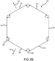
- a common included angle ⁇ exists between each adjacent pair of faces 134 of the first polygon mirror 130 (e.g., Figure 2B ).
- adjacent faces 134 may intersect along a line, any appropriate transition may be used between each adjacent pair of faces 134 (e.g., a chamfer; a rounded or convex transition surface).
- the spacing between a pair of adjacent ends 136 may be referred to as defining a length dimension of the corresponding face 134) will determine where the laser beam 122 impacts the surface 22 of the substrate 20 in the x dimension noted in Figure 2A .
- the mirror 150 may be disposed between the first polygon mirror 130 and the substrate 20 along the optical path of the laser beam 122 proceeding from the laser 120 to the substrate 20, but again the mirror 150 may be disposed at any appropriate position along the noted optical path.
- the position of the mirror 150 is controlled by a drive 160 (e.g., a servomotor or a galvanometer) that rotates the mirror 150 about a rotational axis 152.
- the mirror 150 may be referred to as a galvanometer mirror or scanner 150.
- the position of the mirror 150 controls where the laser beam 122 impacts the surface 22 of the substrate 20 in the y dimension noted in Figure 2A .
- One or more other optical components may be located along the optical path between the mirror 150 and the substrate 20, for instance such that the laser beam 122 impacts the substrate 20 normal to its surface 22.
- Figure 2A shows a plurality of row sets 30 that extend in the x dimension and that are spaced from one another in the y dimension (e.g., the plurality of row sets 30 may be disposed in parallel relation to one another).
- Each row set 30 may be characterized as including a plurality of rows 32 that also extend in the x dimension and that are spaced from one another in the y dimension (e.g., the plurality of rows 32 may be disposed in parallel relation to one another).
- the laser 120 may be activated such that its laser beam 122 impacts the surface 22 of the substrate 20 at each of the locations shown in Figure 2C to define a plurality of perforations 12 in each row set 30, where each of these perforations 12 will ultimately have a predetermined perimeter configuration, and where the perforations 12 in each row set 30 are spaced from one another in any appropriate fashion (e.g., an equally spaced relation within the given row set 30).
- the mirror 150 may be moved to a fixed position where the laser beam 122 will impact the surface 22 of the substrate 20 along one of the rows 32 (or between an adjacent pair of rows 32) of a particular row set 30.
- the laser 120 will be pulsed such that it impacts the surface 22 of the substrate 20 at predetermined locations along the given row 32 (or in the x dimension) to define a corresponding portion of each of the perforations 12, and that is achieved by the laser beam 122 being reflected from a face 134 of the first polygon mirror 130 as it is being rotated at a constant rotational speed about its rotational axis 132.
- the location of where the laser beam 122 impacts a face 134 of the first polygon mirror 130 determines where the laser beam 122 impacts the surface 22 of the substrate 20 in the x dimension.
- the mirror 150 may be incremented between a number of different fixed positions such that the laser beam 122 will impact the surface 22 of the substrate 20 along each of the rows 32 (or between each of the rows 32) of a particular row set 30 to define each of the desired perforations 12 in this row set 30 and where each perforation 12 will ultimately have a predetermined perimeter configuration.
- the mirror 150 may be positioned such that the laser beam 122 will impact the surface 22 of the substrate 20 on the second row 32 (the second down from the top in the view of Figure 2C ) of the upper row set 30 in the view of Figure 2C . With the mirror 150 remaining in this fixed position, the laser 120 may be pulsed and reflected by one or more faces 134 of the rotating first polygon mirror 130 to impact the surface 22 of the substrate 20 at the locations shown in Figure 2C (these locations being spaced from one another in the x dimension but occupying the same position in the y dimension).
- the mirror 150 may be incremented/moved to a position where the laser beam 122 will impact the surface 22 of the substrate 20 on the next row 32 proceeding in the y dimension (e.g., to another location in the y dimension).
- the laser 120 may be pulsed and reflected by one or more faces 134 of the rotating first polygon mirror 130 to impact the surface 22 of the substrate 20 at the locations shown in Figure 2C (these locations being spaced from one another in the x dimension but occupying the same position in the y dimension). This may be repeated until each of the perforations 12 in the row set 30 have been defined, and also may be repeated for each row set 30 in which one or more perforations 12 are to be defined.
- the mirror 150 is moved in increments dy to form the desired perforations 12 in a particular row set 30, and is moved in a larger increment Dy to move from one row set 30 to an adjacent row set 30.
- the perforation system 100 may be operated to scan or sequence in a top-to-down fashion in the view shown in Figure 2C , and where the entire depth of each perforation in a given row 32 may be defined prior to proceeding to the next row 32 in the same row set 30 (or more generally to another location in the y dimension), other operational configurations may be utilized.
- perforations 12 may be partially defined in each row 32 of a given row set 30, although this would require more incremental movements of the mirror 150 (e.g., 1 ⁇ 2 of the desired perforation depth for each perforation 12 in a given row set 30 may be defined by a first set of incremental movements of the mirror 150, and this may then be repeated to define the remainder of the desired perforation depth for each perforation in this same row set 30), and this may apply to each row set 30.
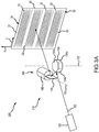
- FIG. 3A A perforation system in accordance with various embodiments is illustrated in Figure 3A , is identified by reference numeral 200, and is configured/operated to form a plurality of perforations of a predetermined perimeter configuration and size on a surface 22 of a substrate 20 in accordance with the foregoing.
- Corresponding components between the perforation system 100 of Figure 2A and the perforation system 200 of Figure 3A are identified by the same reference numeral and the corresponding discussion above remains applicable to the perforation system 200 unless otherwise noted.
- the perforation system 200 may be characterized as including an optical system 210. Components of this optical system 210 include the laser 120, a first polygon mirror 130a, and the mirror 150.
- the first polygon mirror 130a and mirror 150 may be characterized as a scanner 290.
- the first polygon mirror 130a is disposed between the laser 120 and the mirror 150 along the optical path of the laser beam 122 proceeding from the laser 120 to the substrate 20, although both the first polygon mirror 130a and the mirror 150 may be disposed at any appropriate position along the noted optical path.
- Operation of the perforation system 200 may include continuously rotating the first polygon mirror 130a at a constant rotational velocity about its rotational axis 132.
- a plurality of faces 134a are disposed on a perimeter of the first polygon mirror 130a.
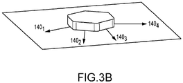
- any appropriate number of faces 134a may be disposed on the perimeter of the first polygon mirror 130a (six in the illustrated embodiment). Each of these faces 134a are flat or planar surfaces in one or more embodiments. Unlike the case of the perforation system 100 discussed above, these faces 134a are each disposed in a different orientation relative to the rotational axis 132 of the first polygon mirror 130a and as shown in Figure 3B .
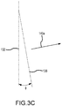
- Figure 3C shows the orientation of the rotational axis 132 of the first polygon mirror 130a, along with a reference plane 138 that corresponds with one of the faces 134a.
- a vector 140a that is orthogonal to this face 134a is disposed in an orientation other than perpendicular to the rotational axis 132 of the first polygon mirror 130a.
- the vector 140a will be in a different orientation for each of the faces 134a of the first polygon mirror 130a when in the same rotational or angular position relative to the rotational axis 132 (see Figure 3B ).
- adjacent faces 134a of the first polygon mirror 130a may intersect along a line
- any appropriate transition may be used between each adjacent pair of faces 134a (e.g., a chamfer; a rounded or convex transition surface).
- a chamfer a rounded or convex transition surface
- the laser beam 122 impacts a given face 134a between its corresponding pair of ends 136 (or along the length dimension of such a face 134a) will determine where the laser beam 122 impacts the surface 22 of the substrate 20 in the x dimension noted in Figure 3A .
- the position of the mirror 150 again is controlled by the drive 160.
- the position of the mirror 150 at least partially controls where the laser beam 122 impacts the surface 22 of the substrate 20 in the y dimension noted in Figure 3A .
- the different orientations of the faces 134a of the first polygon mirror 130 also controls where the laser beam 122 impacts the surface 22 of the substrate 20 in the y dimension noted in Figure 3A .
- One or more other optical components may be located along the optical path between the mirror 150 and the substrate 20, for instance such that the laser beam 122 impacts the substrate 20 normal to its surface 22.
- Figure 3A shows a plurality of row sets 30 that extend in the x dimension and that are spaced from one another in the y dimension (e.g., the plurality of row sets 30 may be disposed in parallel relation to one another).
- Each row set 30 may be characterized as including a plurality of rows 32 that also extend in the x dimension and that are spaced from one another in the y dimension (e.g., the plurality of rows 32 may be disposed in parallel relation to one another).
- the laser 120 may be activated such that its laser beam 122 impacts the surface 22 of the substrate 20 at each of the locations shown in Figure 3D to define a plurality of perforations 12 in each row set 30, where each of these perforations 12 will ultimately have a predetermined perimeter configuration and size, and where the perforations 12 in each row set 30 are spaced from one another in any appropriate fashion (e.g., an equally spaced relation within the given row set 30).
- the mirror 150 may be moved to a fixed position where the laser beam 122 will impact the surface 22 of the substrate 20 within a particular row set 30 at each of a plurality of locations that are spaced in the y dimension (depending upon from which face 134a the laser beam 122 was reflected). That is, each face 134a of the first polygon mirror 130a is associated with a different location in the y dimension shown in Figure 3D .
- the laser 120 will be pulsed such that it impacts the surface 22 of the substrate 20 at predetermined locations (either along a given row 32 or between an adjacent pair of rows 32 in the corresponding row set 30 and as shown in Figure 3D ) to define a corresponding portion of each of the perforations 12 in the row set 30, and that is achieved by the laser beam 122 being reflected from a corresponding face 134a of the first polygon mirror 130a as it is being rotated at a constant rotational speed about its rotational axis 132.
- the location of where the laser beam 122 impacts a face 134a of the first polygon mirror 130a determines where the laser beam 122 impacts the surface 22 of the substrate 20 in the x dimension (and in the corresponding row 32 or between the corresponding pair of adjacent rows 32).
- the mirror 150 of the perforation system 200 of Figure 3A need not be incremented to different fixed positions in order for the laser beam 122 to scan each of the rows 32 of a particular row set 30 to define each of the desired perforations 12 in this row set 30 (and again where each perforation 12 has a predetermined perimeter configuration and size).
- the mirror 150 need not be moved to define the entirety of each perforation 12 in the same row set 30 on the substrate 20 - the different impact locations of the laser beam 122 in the y dimension are provided by having the first polygon mirror 130a include a plurality of faces 134a that are each disposed in a different orientation relative to the rotational axis 132.
- the mirror 150 may be positioned such that the laser beam 122 will impact the surface 22 of the substrate 20 within the upper row set 30 in the view of Figure 3D (location 1). With the mirror 150 remaining in this fixed position, the laser 120 may be pulsed and reflected by the various faces 134a of the rotating first polygon mirror 130 to impact the surface 22 of the substrate 20 at the locations shown in Figure 3D (again, each face 134a of the first polygon mirror 130a will be associated with a different location within the y dimension of a given row set 30). This may need to be repeated a plurality of times in order for each of the perforations 12 (within a common row set 30) to extend to the desired depth within the substrate 20 (including for a given perforation 12 to extend through the entire thickness of the substrate 20).
- the mirror 150 may be moved to a different fixed position where the laser beam 122 will impact the surface 22 of the substrate 20 within a different row set 30 at each of a plurality of locations that are spaced in the y dimension (depending upon from which face 134a the laser beam 122 was reflected), for instance locations 2, 3, 4, and 5 shown in Figure 3D .
- This movement of the mirror 150 is shown as Dy in Figure 3D .
- perforations 12 may be partially defined in each of the row sets 30, although this would require more incremental movements of the mirror 150 (e.g., 1 ⁇ 2 of the desired perforation depth for each perforation 12 in each row set 30 may be defined by a first set of incremental movements of the mirror 150, and this may then be repeated to define the remainder of the desired perforation depth for each perforation 12 in each row set 30 by repeating the noted incremental movements of the mirror 150).
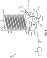
- a perforation system in accordance with various embodiments is illustrated in Figure 4 , is identified by reference numeral 300, and is configured/operated to form a plurality of perforations of a predetermined perimeter configuration and size on a surface 22 of a substrate 20 in accordance with the foregoing.
- Corresponding components between the perforation system 100 of Figure 2A and the perforation system 300 of Figure 4 are identified by the same reference numerals and the corresponding discussion above remains applicable to the perforation system 300 unless otherwise noted.
- the perforation system 300 may be characterized as including an optical system 310.
- Components of this optical system 310 include the laser 120, the first polygon mirror 130, a second polygon mirror 180, and the mirror 150, and each of which may be disposed at any appropriate position along the optical path proceeding from the laser 120 to the substrate 20.
- the first polygon mirror 130, the second polygon mirror 180, and the mirror 150 may be characterized as a scanner 390.
- the first polygon mirror 130 may be disposed between the laser 120 and the second polygon mirror 180 along the optical path of the laser beam 122 proceeding from the laser 120 to the substrate 20, and is rotated at a constant rotational velocity about its rotational axis 132.
- the first polygon mirror 130 of the perforation system 300 of Figure 4 controls where the laser beam 122 impacts the surface 22 of the substrate 20 in the x dimension. More specifically, where the laser beam 122 impacts a given face 134 along its length dimension will determine where the laser beam 122 impacts the surface 22 of the substrate 20 in the x dimension noted in Figure 4 .
- the second polygon mirror 180 may be disposed between the first polygon mirror 130 and the mirror 150 along the optical path of the laser beam 122 proceeding from the laser beam 122 to the substrate 20. Operation of the perforation system 300 may include continuously rotating the second polygon mirror 180 at a constant rotational velocity about its rotational axis 182 (e.g., an appropriate rotational drive may be interconnected with the second polygon mirror 180).
- a plurality of faces 184 are disposed on a perimeter of the second polygon mirror 180. Any appropriate number of faces 184 may be disposed on the perimeter of the second polygon mirror 180 (six in the illustrated embodiment). Each of these faces 184 are flat or planar surfaces in one or more embodiments.
- these faces 184 are disposed parallel to the rotational axis 182 of the second polygon mirror 180 for the case of the perforation system 300 (e.g., in accord with the first polygon mirror 130 and as described above).
- a vector that is normal to its corresponding face 184 is parallel to or colinear with the same vector of each other face 184 of the second polygon mirror 180 when disposed in the same rotational or angular position relative to the rotational axis 182.
- a common included angle exists between each adjacent pair of faces 184 of the second polygon mirror 180, similar to the first polygon mirror 130 discussed above.
- adjacent faces 184 may intersect along a line, any appropriate transition may be used between each adjacent pair of faces 184 (e.g., a chamfer; a rounded or convex transition surface).
- a chamfer a rounded or convex transition surface
- the laser beam 122 impacts a given face 184 between its corresponding pair of ends 186 (and that may be referred to as defining a length dimension of such a face 184) will at least in part determine where the laser beam 122 impacts the surface 22 of the substrate 20 in the y dimension noted in Figure 4 .
- the orientation of the rotational axis 132 for the first polygon mirror 130 is different than the orientation of the rotational axis 182 for the second polygon mirror 180.
- the rotational axis 132 of the first polygon mirror 130 is orientated to control where the laser beam 122 impacts the surface 22 of the substrate 20 in the x dimension noted in Figure 4 .
- the rotational axis 182 of the second polygon mirror 180 is orientated to control where the laser beam 122 impacts the surface 22 of the substrate 20 in the y dimension noted in Figure 4 .
- the first polygon mirror 130 may be rotated at a different rate than the second polygon mirror 180, including where the first polygon mirror 130 is rotated at a higher rotational speed than the second polygon mirror 180 (although both polygon mirrors 130, 180 will typically each be rotated at a constant rotational speed).
- the first polygon mirror 130 and the second polygon mirror 180 could be rotated at a common rotational speed if the number of faces 134 for the first polygon mirror 130 differed from the number of faces 184 for the second polygon mirror 180.
- the mirror 150 may be disposed between the second polygon mirror 180 and the substrate 20 along the optical path of the laser beam 122 proceeding from the laser 120 to the substrate 20.
- the position of the mirror 150 is again controlled by the drive 160 that rotates the mirror 150 about its rotational axis 152.
- the position of the mirror 150 controls in part where the laser beam 122 impacts the surface 22 of the substrate 20 in the y dimension noted on Figure 4 (again, the rotating second polygon mirror 180 also controls in part where the laser beam 122 impacts the surface 22 of the substrate 20 in the y dimension noted on Figure 4 ).
- One or more other optical components may be located along the optical path between the mirror 150 and the substrate 20, for instance such that the laser beam 122 impacts the substrate 20 normal to its surface 22.
- FIG 4 shows a plurality of row sets 30 that each extend in the x dimension and that are spaced from one another in the y dimension (e.g., the plurality of row sets 30 may be disposed in parallel relation to one another).
- Each row set 30 includes a plurality of rows 32 (see Figure 3D ) that also extend in the x dimension and that are spaced from one another in the y dimension (e.g., the plurality of rows in a given row set 30 may be disposed in parallel relation to one another).
- the laser 120 may be activated such that its laser beam 122 impacts the surface 22 of the substrate 20 at each of the locations shown in Figure 3D to define a plurality of perforations 12 in a given row set 30, where each of these perforations 12 will ultimately have a predetermined perimeter configuration and size, and where the perforations 12 in a given row set 30 are spaced from one another in any appropriate fashion (e.g., an equally spaced relation within the given row set 30).
- Each of the row sets 30 are separately scanned by the laser 120 in the case of the perforation system 300 of Figure 4 .
- the mirror 150 in the case of the perforation system 300 of Figure 4 may be moved to a fixed position where the laser beam 122 will impact the surface 22 of the substrate 20 within a particular row set 30 at each of a plurality of locations that are spaced in the y dimension (via the rotating second polygon mirror 180). Within this row set 30, where the laser beam 122 will impact the surface 22 of the substrate 20 in the y dimension will depend upon where the laser beam 122 impacts a face 184 of the second polygon mirror 180 along its length dimension.
- the laser 120 will further be pulsed such that it impacts the surface 22 of the substrate 20 at predetermined locations in the x dimension (either along a given row or between an adjacent pair of rows of a corresponding row set 30) to define a corresponding portion of each of the perforations 12 in the row set 30, and that is achieved by the laser beam 122 being reflected from a corresponding face 134 of the first polygon mirror 130 as it is being rotated at a constant rotational speed about its rotational axis 132.
- the location of where the laser beam 122 impacts a face 134 of the first polygon mirror 130 determines where the laser beam 122 impacts the surface 22 of the substrate 20 in the x dimension (and in the corresponding row or between the corresponding pair of adjacent rows of the current row set 30).
- the mirror 150 of the perforation system 300 of Figure 4 need not be incremented to different fixed positions in order for the laser beam 122 to scan each of the rows of a particular row set 30 to define each of the desired perforations 12 in this row set 30 (and again where each perforation 12 will ultimately have a predetermined perimeter configuration and size).
- This capacity for different locations in the y dimension within a particular row set 30 is provided by the rotating second polygon mirror 180.
- the mirror 150 may be positioned such that the laser beam 122 will impact the surface 22 of the substrate 20 within the upper row set 30 in the view of Figure 3D (i.e., location 1).
- the laser 120 may be pulsed and its laser beam 122 reflected by one or more faces 134 of the rotating first polygon mirror 130 (to have the laser beam 122 impact the surface 22 of the substrate 20 at a particular location in the x dimension in the row set 30) and the laser beam 122 will also be reflected by one or more faces 184 of the rotating second polygon mirror 180 (to have the laser beam 122 impact the surface 22 of the substrate 20 at a particular location in the y dimension in the row set 30).
- each of the perforations 12 may need to be repeated a plurality of times in order for each of the perforations 12 (within a common row set 30 - Figure 3D ) to extend to the desired depth within the substrate 20 (including for a given perforation 12 to extend through the entire thickness of the substrate 20).
- the mirror 150 may be moved to a different fixed position (one of locations 2, 3, 4, and 5 shown in Figure 3D ) for repetition in accordance with the foregoing. This movement of the mirror 150 is shown as Dy in Figure 3D .
- the perforation system 300 of Figure 4 may be operated to scan or sequence in a top-to-down fashion in the view shown in Figure 3D , and where the entire depth of each perforation 12 in a given row set 30 is defined prior to proceeding to the next row set 30, other operational configurations may be utilized.
- perforations 12 may be partially defined in each of the row sets 30, although this would require more incremental movements of the mirror 150 (e.g., 1 ⁇ 2 of the desired perforation depth for each perforation 12 in each row set 30 may be defined by a first set of incremental movements of the mirror 150, and this may then be repeated to define the remainder of the desired perforation depth for each perforation in each row set 30 by repeating the noted incremental movements of the mirror 150).
- the laser 120 may separately scan the various row sets 30 in any order (i.e., it is not required to sequence through the row sets 30 in order).
- a perforation system in accordance with various embodiments is illustrated in Figure 5 , is identified by reference numeral 300a, and is configured/operated to form a plurality of perforations of a predetermined perimeter configuration and size on a surface 22 of a substrate 20 in accordance with the foregoing.
- the perforation system 300a uses the same components as the perforation system 300 of Figure 4 (the first polygon mirror 130, the second polygon mirror 180, and the mirror 150 may be characterized as a scanner 390). However, the perforation system 300a of Figure 5 is operated differently than the perforation system 300 of Figure 4 to form a plurality of perforations of a predetermined perimeter configuration and size on a surface 22 of a substrate 20 in accordance with the foregoing.
- the second polygon mirror 180 may be rotating at a higher rotational speed than in the case of the perforation system 300 of Figure 4 .
- One or more other optical components may be located along the optical path between the mirror 150 and the substrate 20, for instance such that the laser beam 122 impacts the substrate 20 normal to its surface 22.
- the laser beam 122 from the laser 120 will be scanned to impact various locations in multiple row sets 30 (e.g., Figure 3D ).
- the laser beam 122 from the laser 120 may be scanned to impact various locations in each of the row sets 30 shown in Figure 3D (e.g., scanning from top to bottom in the view shown in Figure 3D for a single, fixed position of the mirror 150).
- This scan may need to be repeated a plurality of times in order for the corresponding portions of the perforations 12 (again, within each of multiple row sets 30) to extend to the desired depth within the substrate 20 (including for a given corresponding portion of each perforation 12 to extend through the entire thickness of the substrate 20).
- the location from which the laser beam 122 is reflected by a face 134 of the first polygon mirror 130 will determine the location in the x dimension where the laser beam 122 will impact the surface 22 of the substrate 20, whereas the location from which the laser beam 122 is reflected by a face 184 of the second polygon mirror 130 will determine the location in the y dimension where the laser beam 122 will impact the surface 22 of the substrate 20, all for a given fixed position of the mirror 150.
- each different position of the mirror will change the y dimension of the area of the substrate 20 that is scanned in accordance with the foregoing (see representative different positions a, b, and c in Figure 5A ).
- this will ultimately define a plurality of perforations 12 in the substrate 20, and where each such perforation 12 has a predetermined perimeter configuration and size.
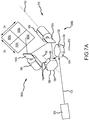
- a perforation system accordance with various embodiments is illustrated in Figure 7A , is identified by reference numeral 300b, and is configured/operated to form a plurality of perforations (e.g., perforations 12 - Figure 7B ) of a predetermined perimeter configuration and size on a surface of a substrate (e.g., substrate 20 - Figure 7B ) in accordance with the foregoing.
- the perforation system 300b includes the first polygon mirror 130 and the second polygon mirror 180 in accordance with the perforation systems 300, 300a.
- the perforation system 300b further includes a first positioning mirror 150a (e.g., in accordance with the mirror 150 discussed above in relation to the perforation systems 300, 300a), and a second positioning mirror 150b.
- the position of the second positioning mirror 150b is controlled by a drive 160 that rotates the second positioning mirror 150b about rotational axis 152b.
- the rotational axis 152a of the first positioning mirror 150a, and the rotational axis 152b of the second positioning mirror 150b are disposed in different orientations.
- the first polygon mirror 130, the second polygon mirror 180, the first positioning mirror 150a, and the second positioning mirror 150b each may be disposed at any appropriate position along the optical path proceeding from the laser 120 to the substrate 20.
- the first polygon mirror 130, the second polygon mirror 180, the first positioning mirror 150a, and the second positioning mirror 150b may be characterized as a scanner 390b.
- the second positioning mirror 150b may be moved/adjusted to accommodate formation of one or more perforations in different quadrants that occupy different positions in a first dimension (e.g., an x dimension).
- the first positioning mirror 150a may be moved/adjusted to accommodate formation of one or more perforations in different quadrants that occupy different positions in a second dimension (e.g., a y dimension) that is orthogonal to the first dimension.
- Figure 7B illustrates four different quadrants 500a, 500b, 500c, and 500d.
- the second positioning mirror 150b provides for an adjustment in the x dimension (DX in Figure 7B ), for instance to move from quadrant 500a to quadrant 500b, or to move from quadrant 500c to quadrant 500d.
- the first positioning mirror 150a provides for an adjustment in the y dimension (DY in Figure 7B ), for instance to move from quadrant 500a to quadrant 500c, or to move from quadrant 500b to quadrant 500d.
- the first polygon mirror 130, the second polygon mirror 180, and the first positioning mirror 150a furthermore may be operated to form one or more perforations 12 in each of these quadrants 500a, 500b, 500c, and 500d in accordance with the perforation system 300 or the perforation system 300b.
- the quadrant 500a and quadrant 500b occupy different positions in the noted first dimension, while the quadrant 500c and quadrant 500d occupy different positions in the noted first dimension.
- the quadrant 500a and the quadrant 500c occupy different positions in the noted second dimension, while the quadrant 500b and quadrant 500d occupy different positions in the noted second dimension.
- the perforation systems 100, 200, 300, 300a discussed above may be used to define a plurality of perforations over an area of a substrate of any appropriate size.
- the perforation system 400 includes an optical system 410, a base 420, and a controller 450.
- the optical system 410 may, for instance, be in accordance with any of the perforation systems 100, 200, 300, 300a discussed above.
- the controller 450 may be operatively interconnected with both the base 420 and the optical system 410, and may be of any appropriate configuration/architecture.
- the controller 450 may be operatively interconnected with the laser 120, the rotational drive source for the polygon mirrors 130/130a, 180, and the drive 160 for the mirror 150.
- the base 420 may be moved in each of an x dimension 430 and a y dimension 440 such that after the optical system 410 has formed perforations on one section of a substrate, the base 420 may be moved such that the optical system 410 may thereafter form perforations on a completely different section of the same substrate. This may be done any appropriate number of times.
- the above-discussed perforation system 100, 200, 300, and 300a are believed to significantly reduce the amount of time to form a plurality of perforations compared to a standard two galvanometer mirror system.
- the advantage becomes more and more relevant as the size of the surface on which perforations are formed increases and when forming at least a certain number of perforations.
- a perforation system is illustrated in Figure 8 and is identified by reference numeral 500.
- Components of the perforation system 500 include a laser system 510 and a scanner 580.
- the laser system 510 creates and outputs a plurality of beamlets 570 (addressed below).
- the scanner 580 moves each of these beamlets 570 in at least two different dimensions on the substrate 20 to define multiple perforations.
- Each beamlet 570 may be moved by the scanner 580 to define a corresponding perforation on the substrate 20.
- the scanner 580 may be of any appropriate configuration, for instance in accordance with the above-described scanners 190, 290, 390, 390a, and 390b.
- the scanner 90 includes a movable first positioning mirror 50a and a movable second positioning mirror 50b.
- Arrow A identifies the direction of a laser system used with the scanner 90
- arrow B identifies the direction of the substrate on which the perforations are formed.
- the output from the laser system includes a plurality of beamlets 40, that are reflected by the first positioning mirror 50a, and then by the second positioning mirror 50b.
- the scanner 90 moves each of these beamlets 40 in at least two different dimensions on the substrate 20 to define multiple perforations in accordance with the foregoing.
- the position of the mirrors 50a, 50b is controlled by a drive 60 (e.g., a servomotor or a galvanometer that rotates the corresponding mirror 50a, 50b about its corresponding rotational axis 52a, 52b).
- the position of the first mirror 50a controls where the beamlets 40 impact the substrate 20 in a first dimension (e.g., an x dimension), while the position of the second mirror 50b controls where the beamlets impact the substrate 20 in a second dimension (e.g., a y dimension) that is orthogonal to the first dimension.
- the rotational axes 52a, 52b are disposed in different orientations.
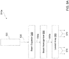
- a representative laser system that may be used by the perforation system 500 of Figure 8 is illustrated in Figure 9A and is identified by reference numeral 510a.
- the laser system 510a includes a laser 520, a beam expander 540, a beam homogenizer 550, and a lenslet array 560 (e.g., an optical beamlet generator).
- the laser 520 outputs a collimated laser beam 530 that is directed to the beam expander 540.
- the beam expander 540 is an optical device that takes the collimated laser beam 530 and expands its size to an expanded laser beam 530a.
- the expanded laser beam 530a is output from the beam expander 540 and is directed to the beam homogenizer 550.
- the beam homogenizer 550 is an optical device that smooths out irregularities in the expanded laser beam 530a output from the beam expander 540, and enhances the uniformity of the expanded laser beam 530a to define an expanded, homogenized laser beam 530b.
- the expanded, homogenized laser beam 530b is output from the beam homogenizer 550 and is directed to the lenslet array 560.
- the lenslet array 560 includes a plurality of lenslets (small lenses) to produce a plurality of beamlets 570 that are directed to the scanner 580 ( Figure 8 ). Each lenslet of the lenslet array 560 produces a corresponding beamlet 570.
- the lenslet array 560 may be configured to generate any appropriate number of beamlets 570, to dispose a plurality of beamlets 570 in any appropriate arrangement/pattern, or both.
- the beamlets 570 are output from the lenslet array 560 in at least substantially parallel relation to one another.
- the lenslet array 560 may generate the plurality of beamlets 570 from a single laser beam (e.g., collimated).
- Beamlets as used herein means a number of discrete laser beams that are generated from a single collimated laser beam (e.g., beamlets may be characterized as a subset of a single collimated laser beam).
- the collective power of the beamlets 570 emitted from the lenslet array 560 at least generally corresponds with the power of the collimated laser beam 530 emitted from the laser 520.
- Various embodiments have the collective power of the beamlets 570 emitted from the lenslet array 560 being at least 90 percent of the power of the collimated laser beam 530.
- a lenslet base or carousel is illustrated in Figure 9B , is identified by reference numeral 600, and may be used in place of the lenslet array 560 for the laser system 510a illustrated in Figure 9A .
- the lenslet carousel 600 includes a plurality of lenslet arrays 560 (e.g., lenslet arrays 560a, 560b, 560c, 560d, and 560e). Any appropriate number of lenslet arrays 560 may be utilized by the lenslet carousel 600.
- Each lenslet array 560 incorporated by carousel 600 includes at least one lenslet.
- lenslet array 560a includes a single lenslet 565a; lenslet array 560b includes three lenslets 565b; lenslet array 560c includes five lenslets 565c; lenslet array 560d includes four lenslets 565d; and lenslet array 560e includes two lenslets 565e.
- Each lenslet array 560 for the carousel 600 may include any appropriate number of lenslets and multiple lenslets may be disposed in any appropriate arrangement/pattern (to output a corresponding arrangement/pattern of beamlets 570 on the substrate 20).
- the lenslet carousel 600 may be moved (e.g., rotated, for instance by a drive 610) to dispose one of its lenslet arrays 560 in the optical path of the laser system 510a of Figure 9A .
- one or more lenslet arrays 560 may be detachably connected to the carousel 600 (e.g., to accommodate changing one lenslet array 560 out for another lenslet array 560). At least some of the lenslet arrays 560 may differ in at least one respect from the other lenslet arrays 560, including where each lenslet array 560 differs from every other lenslet array 560 (e.g., in relation to the number and/or arrangement of the lenslets 565).
- any appropriate number of the lenslet arrays 560 of the carousel 600 could be used to define perforations on the substrate 20 ( Figure 8 ).
- one lenslet array 560 of the carousel 600 could be used to define perforations throughout one region of the substrate 20, while a different lenslet array 560 of the carousel 600 could be used to define perforations throughout a different region of the same substrate 20.
- Two or more lenslet arrays 560 of the carousel 600 could be used to define perforations throughout a common region of the substrate 20.
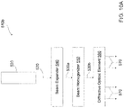
- the laser system 510b includes the laser 520, the beam expander 540, the beam homogenizer 550, and a diffractive optical element 590 (DOE) (e.g., an optical beamlet generator).
- DOE diffractive optical element 590
- the diffractive optical element 590 produces beamlets 570.
- the diffractive optical element 590 may be configured to generate any appropriate number of beamlets 570, to output a plurality of beamlets 570 in any appropriate arrangement/pattern, or both.
- the beamlets 570 are output from the diffractive optical element 590 in at least substantially parallel relation to one another.
- the diffractive optical element 590 may generate the plurality of beamlets 570 from a single laser beam (e.g., collimated).
- a DOE base or carousel is illustrated in Figure 10B , is identified by reference numeral 600', and may be used in place of the diffractive optical element 590 for the laser system 510b illustrated in Figure 10A .
- the DOE carousel 600' includes a plurality of diffractive optical elements 590 (e.g., DOE 590a, DOE 590b, DOE 590c, DOE 590d, and DOE 590e).
- DOEs 590 of the carousel 600' may be of a different configuration, including where each DOE 590 is of a different configuration (e.g., in relation to the number and/or arrangement of the beamlets 570 output from a given DOE 590).
- any appropriate number of diffractive optical elements 590 may be utilized by the DOE carousel 600'.
- Each DOE 590 may be configured to output any appropriate number of beamlets 570 and multiple beamlets 570 may be output from a given DOE 590 in any appropriate arrangement/pattern.
- the DOE carousel 600' may be moved (e.g., rotated, for instance by the drive 610 shown in Figure 9B ) to dispose one of its DOEs 590 in the optical path of the laser system 510b of Figure 10A .
- one or more DOEs 590 may be detachably connected to the carousel 600' (e.g., to accommodate changing one DOE 590 out for another DOE 590).
- any appropriate number of diffractive optical elements 590 of the carousel 600' could be used to define perforations on the substrate 20 ( Figure 8 ).
- one diffractive optical element 590 of the carousel 600' could be used to define perforations throughout one region of the substrate 20, while a different diffractive optical element 590 of the carousel 600' could be used to define perforations throughout a different region of the same substrate 20.
- Two or more diffractive optical elements 590 of the carousel 600' could be used to define perforations throughout a common region of the substrate 20.
- references to "one embodiment,” “an embodiment,” “various embodiments,” etc. indicate that the embodiment described may include a particular feature, structure, or characteristic, but every embodiment may not necessarily include the particular feature, structure, or characteristic. Moreover, such phrases are not necessarily referring to the same embodiment. Further, when a particular feature, structure, or characteristic is described in connection with an embodiment, it is submitted that it is within the knowledge of one skilled in the art to affect such feature, structure, or characteristic in connection with other embodiments whether or not explicitly described. After reading the description, it will be apparent to one skilled in the relevant art(s) how to implement the disclosure in alternative embodiments.
Landscapes
- Physics & Mathematics (AREA)
- Optics & Photonics (AREA)
- Engineering & Computer Science (AREA)
- Plasma & Fusion (AREA)
- Mechanical Engineering (AREA)
- Laser Beam Processing (AREA)
Abstract
Description
- The present disclosure (invention) generally relates to the field of processing substrates and, more particularly, to creating perforations in a substrate.
- Prior technology with laser/scanner perforation on aerostructures materials utilizes a combination of n lasers in conjunction with a galvo-based x-y scanner. Although control of beam direction can be realized with the x-y scanners, it comes at speeds that are much slower than are desired for use in connection with aerostructure production. In a standard two galvanometer mirror system, the mirrors are commanded to some position and the laser is made to emit light. Although flexible in terms of pointing control in two planes, and adequate for many applications, this configuration yields a relatively slow process for creating perforations for aerostructures.
- Various perforation systems are presented herein. Both the configuration of such a perforation system and the operational characteristics of such a perforation system are within the scope of this Summary.
- According to an aspect of the present invention, a perforation system may include a laser system and a scanner. The laser system may include a laser and an optical beamlet generator. The laser system may be configured to input a laser beam (e.g., collimated) to the optical beamlet generator, which then outputs a plurality of beamlets. The scanner (e.g., at least a first movable mirror and a second movable mirror) is configured to simultaneously direct beamlets from the optical beamlet generator toward a substrate and to simultaneously move the plurality of beamlets relative to the substrate in first and second dimensions that are orthogonal to one another. Each beamlet defines a two-dimensional perforation on a surface of the substrate through operation of the scanner. An optical path may be characterized as proceeding from the laser to the substrate on which perforations are formed.
- The optical beamlet generator may be in the form of a lenslet array or a diffractive optical element. The laser system may include a beam expander, a beam homogenizer, or both. The beam expander may be located between the laser and the optical beamlet generator proceeding along the noted optical path. The beam homogenizer may be located between the beam expander and the optical beamlet generator proceeding along the noted optical path. The optical beamlet generator may be located between the beam homogenizer and the scanner proceeding along the noted optical path.
- The perforation system may further include a movable base (e.g., rotatable), which in turn may include a plurality of optical beamlet generators. Each optical beamlet generator may be movable into alignment with the noted optical path by movement of the base. At least one of the optical beamlet generators may be detachably connectable with the base. At least two of the optical beamlet generators may be of a different configuration (e.g., to output a different number of beamlets, a different arrangement/pattern of beamlets, or both).
- Any feature of any other various aspects that is intended to be limited to a "singular" context or the like will be clearly set forth herein by terms such as "only," "single," "limited to," or the like. Merely introducing a feature in accordance with commonly accepted antecedent basis practice does not limit the corresponding feature to the singular (e.g., indicating that a perforation system includes "a lenslet array" alone does not mean that the perforation system includes only a single lenslet array). Moreover, any failure to use phrases such as "at least one" also does not limit the corresponding feature to the singular (e.g., indicating that a perforation system includes "a lenslet array" alone does not mean that the perforation system includes only a single lenslet array). Use of the phrase "at least generally" or the like in relation to a particular feature encompasses the corresponding characteristic and insubstantial variations thereof (e.g., indicating that a mirror surface is at least substantially flat encompasses the mirror surface being flat). Finally, a reference of a feature in conjunction with the phrase "in one embodiment" does not limit the use of the feature to a single embodiment.
- Various aspects are also addressed by the following paragraphs and in the noted combinations:
In one embodiment, there is a perforation system comprising: - a laser system comprising a laser and an optical beamlet generator, wherein said laser system is configured to output a laser beam to said optical beamlet generator, from which said optical beamlet generator outputs a plurality of beamlets; and
- a scanner configured to simultaneously direct said plurality of beamlets from said optical beamlet generator toward a substrate and to simultaneously move said plurality of beamlets relative to the substrate in first and second dimensions that are orthogonal to one another, wherein each beamlet of said plurality of beamlets simultaneously defines a two-dimensional perforation on a surface of the substrate by operation of said scanner, and wherein an optical path extends from said laser to the substrate.
- Optionally, said laser outputs a collimated laser beam.
- Optionally, said laser system further comprises a beam expander.
- Optionally, said beam expander is located between said laser and said optical beamlet generator proceeding along said optical path.
- Optionally, said laser system further comprises a beam homogenizer.
- Optionally, said beam homogenizer is located between said beam expander and said optical beamlet generator proceeding along said optical path.
- Optionally, said optical beamlet generator is located between said beam homogenizer and said scanner proceeding along said optical path.
- Optionally, said scanner comprises a first movable mirror and a second movable mirror.
- Optionally, said first movable mirror controls an impact location of said plurality of beamlets on the substrate in said first dimension, and said second movable mirror controls an impact location of said plurality of beamlets on the substrate in said second dimension.
- Optionally, the perforation system further comprises:
a movable base, wherein said base comprises a plurality of said optical beamlet generators, wherein each said optical beamlet generator is separately movable into alignment with said optical path by movement of said base. - Optionally, at least some of said optical beamlet generators are of a different configuration.
- Optionally, at least one of said optical beamlet generators is detachably connected with said base.
- Optionally, each said optical beamlet generator incorporated by said base is detachably connected with said base.
- Optionally, said optical beamlet generator comprises a lenslet array.
- Optionally, said lenslet array comprises a plurality of lenslets.
- Optionally, said lenslet array generates and outputs said plurality of beamlets.
- Optionally, the perforation system further comprises:
a movable base, wherein said base comprises a plurality of said lenslet arrays, wherein each said lenslet array is separately movable into alignment with said optical path by movement of said base. - Optionally, at least some of said lenslet arrays are of a different configuration.
- Optionally, each said lenslet array comprises at least one lenslet.
- Optionally, each said lenslet array comprises a different number of said at least one lenslet.
- Optionally, each said lenslet array utilizes a different arrangement of said at least one lenslet.
- Optionally, at least one of said lenslet arrays is detachably connected with said base.
- Optionally, each said lenslet array incorporated by said base is detachably connected with said base.
- Optionally, said optical beamlet generator comprises a diffractive optical element.
- Optionally, said diffractive optical element generates and outputs said plurality of beamlets.
- Optionally, the perforation system further comprises:
a movable base, wherein said base comprises a plurality of said diffractive optical elements, wherein each said diffractive optical element is separately movable into alignment with said optical path by movement of said base. - Optionally, at least some of said diffractive optical elements are of a different configuration to provide at least one difference in relation to said plurality of beamlets that are output from a corresponding said diffractive optical element.
- Optionally, at least one of said diffractive optical elements is detachably connected with said base.
- Optionally, each said diffractive optical element incorporated by said base is detachably connected with said base.
- In another embodiment, there is a method of forming a perforation on a substrate comprising:
- generating a plurality of beamlets from a laser beam;
- directing said plurality of beamlets to a scanner;
- operating said scanner to simultaneously contact said plurality of beamlets with said substrate at a plurality of different locations on a substrate within a first dimension and in a second dimension that is orthogonal to said first dimension; and
- forming a plurality of perforations on said substrate using said operating step.
- Optionally, said generating step comprises directing said laser beam to a lenslet array.
- Optionally, said lenslet array comprises a plurality of lenslets, and wherein each lenslet outputs a corresponding beamlet.
- Optionally, said generating step comprises directing said laser beam to a diffractive optical element.
- Optionally, each beamlet defines a different perforation on said substrate from said operating step.
- Optionally, a base comprises a plurality of optical beamlet generators, and said method further comprises:
moving said base to dispose a first optical beamlet generator of said base in an optical path of said laser beam, wherein said generating step comprises directing said laser beam through said first optical beamlet generator. - Optionally, said generating step comprises using said first optical beamlet generator to form a first plurality of perforations on a first region of said substrate by said operating step.
- Optionally, the method further comprises:
moving said base to dispose a second optical beamlet generator of said base in said optical path of said laser beam, wherein said generating step comprises directing said laser beam through said second optical beamlet generator to form a second plurality of perforations in the same said first region of said substrate by said operating step. - Optionally, the method further comprises:
moving said base to dispose a second optical beamlet generator of said base in said optical path of said laser beam, wherein said generating step comprises directing said laser beam through said second optical beamlet generator to form a second plurality of perforations outside of said first region of said substrate by said operating step. - Optionally, said laser beam is a collimated laser beam.
-
-
Figure 1A is a cross-sectional view of a substrate with a perforation in the form of a through-hole; -
Figure 1B is a cross-sectional view of a substrate with a perforation in the form of a recess or blind hole; -
Figure 1C is a plan view of representative perforation with a circular perimeter or perimeter configuration; -
Figure 1D is a plan view of a portion of a substrate with a plurality of perforations of one representative perimeter configuration or perforation profile; - Figure IE is a plan view of a portion of a substrate with a plurality of perforations of another representative perimeter configuration or perforation profile;
-
Figure 2A is a schematic of a perforation system that utilizes an optical system having a rotatable polygon mirror to define a plurality of perforations on a substrate; -
Figure 2B is a top view of the polygon mirror used by the perforation system ofFigure 2A ; -
Figure 2C shows a representative scanning configuration for forming at least generally circular perforations on a substrate using the perforation system ofFigure 2A ; -
Figure 3A is a schematic of a perforation system that utilizes an optical system having a rotatable polygon mirror to define a plurality of perforations on a substrate; -
Figure 3B is a perspective view of the polygon mirror used by the perforation system ofFigure 3A , and illustrating each of the faces of the polygon mirror having normal vectors that are disposed in different orientations when disposed in the same rotational/angular position; -
Figure 3C is a schematic that illustrates an included angle between a rotational axis of the polygon mirror used by the perforation system ofFigure 3A and a vector that is normal to one of its faces; -
Figure 3D shows a representative scanning configuration for forming at least generally circular perforations on a substrate using the perforation system ofFigure 3A ; -
Figure 4 illustrates a perforation system that utilizes an optical system having rotatable polygon mirrors and a first mirror that operates in a first operational mode to define a plurality of perforations on a substrate; -
Figure 5 illustrates a perforation system that utilizes an optical system having rotatable polygon mirrors and a first mirror that operates in a second operational mode to define a plurality of perforations on a substrate (Figure 5A being an enlargement of the noted portion ofFigure 5 ); -
Figure 6 is a schematic of a perforation system that may utilize an optical system, such as the optical systems shown inFigures 2A ,3A ,4 , and5 ; -
Figure 7A illustrates a perforation system that utilizes a first polygon mirror, a second polygon mirror, a first positioning mirror, and a second positioning mirror that accommodates formation of perforations in each of a number of different quadrants; -
Figure 7B is a schematic of perforations formed in different quadrants using the perforation system ofFigure 7A ; -
Figure 8 illustrates a perforation system that utilizes beamlets; -
Figure 8A illustrates a scanner that may be used by the perforation system ofFigure 8 ; -
Figure 9A is a schematic of a laser system that may be used by the perforation system ofFigure 8 , where this laser system utilizes a lenslet array; -
Figure 9B is a perspective view of a movable base that incorporates a plurality of lenslet arrays; -
Figure 10A is a schematic of a laser system that may be used by the perforation system ofFigure 8 , where this laser system utilizes a diffractive optical element; and -
Figure 10B is a perspective view of a movable base that incorporates a plurality of diffractive optical elements. - Various embodiments of perforation systems are disclosed herein that may be configured/operated to form one or more perforations on a substrate of any appropriate configuration (e.g., substrate in the form of a plate or plate-like structure; a substrate in the form of a curved structure), on a substrate formed from any appropriate material or combination of materials (e.g., a composite, CFRP (carbon fiber reinforced polymer), CMC (ceramic matrix composite), GFRP (glass fiber reinforced polymer), metal, alloys, ceramics), and including all combinations thereof. These perforations may be of any desired perimeter configuration (e.g., a shape or profile of the perforation in a plan view) and/or size.
Figure 1A illustrates asubstrate 10a having such aperforation 12a in the form of a through-hole (i.e., theperforation 12a extends completely through thesubstrate 10a), where thisperforation 12a has aperimeter 14a that defines the perimeter configuration of theperforation 12a.Figure 1B illustrates asubstrate 10b having such aperforation 12b in the form of a recess or blind hole (i.e., theperforation 12b fails to extend completely through thesubstrate 10b, so theperforation 12b instead defines a concave recess on a surface of thesubstrate 10b), where thisperforation 12b has aperimeter 14b that defines the perimeter configuration of theperforation 12b.Figure 1C is a plan view of aperforation 12 having acircular perimeter 14, and that may be utilized for theperforation 12a ofFigure 1A or theperforation 12b ofFigure 1B . - The embodiments of perforation systems disclosed herein may be configured/operated to form any appropriate number of perforations on a substrate, in any appropriate layout/arrangement, and with any appropriate spacing between adjacent pairs of perforations. Representative layouts/arrangements of perforations that may be formed by the embodiments of perforation systems disclosed herein are illustrated in
Figures 1D and 1E . Thesubstrate 10c ofFigure 1D includes a plurality ofcircular perforations 12c that are disposed in a plurality of rows that are spaced from one another. Thesubstrate 10d of Figure IE includes a plurality ofsquare perforations 12d that are disposed in a plurality of rows that are spaced from one another. Any appropriate spacing between adjacent pairs of perforations in a given row may be utilized, including a common spacing between adjacent pairs of perforations throughout a given row. The same or a different spacing between adjacent pairs of perforations may be utilized in one or more rows. - Perforations formed by any of the embodiments of perforation systems disclosed herein may provide any appropriate function or combination of functions. Representative functions for these perforations on a surface of a substrate include without limitation addressing acoustics (dampening) (the addition of perforations to a surface of a substrate may be characterized as an acoustic treatment of the substrate), addressing aerodynamic drag (e.g., improving laminar flow), surface conditioning (e.g., to enhance bonding, to enhance hydrophobic properties), cutting, trimming, welding, and the like. One application for the embodiments of perforation systems disclosed herein is to create perforations on a substrate that is used as an aerostructure (e.g., a component of an airframe for an aircraft; an exterior surface of an aerostructure).
- A perforation system in accordance with various embodiments is illustrated in
Figure 2A , is identified byreference numeral 100, and is configured/operated to form a plurality of perforations of a predetermined perimeter configuration and size on asurface 22 of asubstrate 20 in accordance with the foregoing. Theperforation system 100 may be characterized as including anoptical system 110. Components of thisoptical system 110 include alaser 120, afirst polygon mirror 130, and amirror 150. Thefirst polygon mirror 130 andmirror 150 may be characterized as ascanner 190. - The
laser 120 may be of any appropriate type/configuration, of any appropriate pulse repetition rate, pulse width, power, and wavelength (e.g., YAG; 100 kHz, 10 ns, 100 W, 1064 nm), and generates alaser beam 122 that proceeds along an optical path to thesubstrate 20. Thelaser beam 122 may be output by thelaser 120 in the form of a pulse that is issued at any appropriate frequency (e.g., a fixed frequency). One or more embodiments has the position of thelaser 120 being fixed relative to the first polygon mirror 130 - more specifically the position of thelaser 120 may be fixed relative to the position of arotational axis 132 of thefirst polygon mirror 130. The impacting of thelaser beam 122 on thesurface 22 of thesubstrate 20 removes corresponding material from the substrate 20 (e.g., via ablation, vaporization, or the like of the material defining the substrate 20). - The
first polygon mirror 130 may be disposed between thelaser 120 and themirror 150 along the optical path of thelaser beam 122 proceeding from thelaser 120 to thesubstrate 20, although both thefirst polygon mirror 130 and the 150 mirror may be disposed at any appropriate position along the noted optical path. Operation of theperforation system 100 may include continuously rotating thefirst polygon mirror 130 at a constant rotational velocity about its rotational axis 132 (e.g., an appropriate rotational drive may be interconnected with the first polygon mirror 130). A plurality offaces 134 are disposed on a perimeter of thefirst polygon mirror 130. Any appropriate number offaces 134 may be disposed on the perimeter of the first polygon mirror 130 (six in the illustrated embodiment). Each of thesefaces 134 are flat or planar surfaces in one or more embodiments. Moreover, thesefaces 134 are each disposed at least substantially parallel to therotational axis 132 of thefirst polygon mirror 130 for the case of theperforation system 100. As such, avector 140 that is normal to itscorresponding face 134 is parallel to or colinear with thesame vector 140 of eachother face 134 of thefirst polygon mirror 130 when disposed in the same rotational or angular position relative to therotational axis 132. - A common included angle θ exists between each adjacent pair of
faces 134 of the first polygon mirror 130 (e.g.,Figure 2B ). Althoughadjacent faces 134 may intersect along a line, any appropriate transition may be used between each adjacent pair of faces 134 (e.g., a chamfer; a rounded or convex transition surface). Where thelaser beam 122 impacts a givenface 134 between its corresponding pair of ends 136 (the spacing between a pair ofadjacent ends 136 may be referred to as defining a length dimension of the corresponding face 134) will determine where thelaser beam 122 impacts thesurface 22 of thesubstrate 20 in the x dimension noted inFigure 2A . - The
mirror 150 may be disposed between thefirst polygon mirror 130 and thesubstrate 20 along the optical path of thelaser beam 122 proceeding from thelaser 120 to thesubstrate 20, but again themirror 150 may be disposed at any appropriate position along the noted optical path. The position of themirror 150 is controlled by a drive 160 (e.g., a servomotor or a galvanometer) that rotates themirror 150 about arotational axis 152. Themirror 150 may be referred to as a galvanometer mirror orscanner 150. In any case, the position of themirror 150 controls where thelaser beam 122 impacts thesurface 22 of thesubstrate 20 in the y dimension noted inFigure 2A . One or more other optical components may be located along the optical path between themirror 150 and thesubstrate 20, for instance such that thelaser beam 122 impacts thesubstrate 20 normal to itssurface 22. - Operation of the
perforation system 100 will be addressed with regard toFigures 2A and2C .Figure 2A shows a plurality of row sets 30 that extend in the x dimension and that are spaced from one another in the y dimension (e.g., the plurality of row sets 30 may be disposed in parallel relation to one another). Each row set 30 may be characterized as including a plurality ofrows 32 that also extend in the x dimension and that are spaced from one another in the y dimension (e.g., the plurality ofrows 32 may be disposed in parallel relation to one another). Generally and as shown inFigure 2C , thelaser 120 may be activated such that itslaser beam 122 impacts thesurface 22 of thesubstrate 20 at each of the locations shown inFigure 2C to define a plurality ofperforations 12 in each row set 30, where each of theseperforations 12 will ultimately have a predetermined perimeter configuration, and where theperforations 12 in each row set 30 are spaced from one another in any appropriate fashion (e.g., an equally spaced relation within the given row set 30). - Generally, the
mirror 150 may be moved to a fixed position where thelaser beam 122 will impact thesurface 22 of thesubstrate 20 along one of the rows 32 (or between an adjacent pair of rows 32) of a particular row set 30. Thelaser 120 will be pulsed such that it impacts thesurface 22 of thesubstrate 20 at predetermined locations along the given row 32 (or in the x dimension) to define a corresponding portion of each of theperforations 12, and that is achieved by thelaser beam 122 being reflected from aface 134 of thefirst polygon mirror 130 as it is being rotated at a constant rotational speed about itsrotational axis 132. Again, the location of where thelaser beam 122 impacts aface 134 of the first polygon mirror 130 (e.g., where thelaser beam 122 impacts aface 134 along its length dimension), determines where thelaser beam 122 impacts thesurface 22 of thesubstrate 20 in the x dimension. Themirror 150 may be incremented between a number of different fixed positions such that thelaser beam 122 will impact thesurface 22 of thesubstrate 20 along each of the rows 32 (or between each of the rows 32) of a particular row set 30 to define each of the desiredperforations 12 in this row set 30 and where eachperforation 12 will ultimately have a predetermined perimeter configuration. - One way in which the
perforations 12 shown inFigure 2C may be produced will be summarized. Themirror 150 may be positioned such that thelaser beam 122 will impact thesurface 22 of thesubstrate 20 on the second row 32 (the second down from the top in the view ofFigure 2C ) of the upper row set 30 in the view ofFigure 2C . With themirror 150 remaining in this fixed position, thelaser 120 may be pulsed and reflected by one or more faces 134 of the rotatingfirst polygon mirror 130 to impact thesurface 22 of thesubstrate 20 at the locations shown inFigure 2C (these locations being spaced from one another in the x dimension but occupying the same position in the y dimension). This may be repeated a plurality of times in order for each of theperforations 12 to extend to the desired depth within the substrate 20 (including for a givenperforation 12 to extend through the entire thickness of the substrate 20). Thereafter, themirror 150 may be incremented/moved to a position where thelaser beam 122 will impact thesurface 22 of thesubstrate 20 on thenext row 32 proceeding in the y dimension (e.g., to another location in the y dimension). With themirror 150 remaining in this new fixed position, again thelaser 120 may be pulsed and reflected by one or more faces 134 of the rotatingfirst polygon mirror 130 to impact thesurface 22 of thesubstrate 20 at the locations shown inFigure 2C (these locations being spaced from one another in the x dimension but occupying the same position in the y dimension). This may be repeated until each of theperforations 12 in the row set 30 have been defined, and also may be repeated for each row set 30 in which one ormore perforations 12 are to be defined. - Based upon the foregoing, it should be appreciated that the
mirror 150 is moved in increments dy to form the desiredperforations 12 in a particular row set 30, and is moved in a larger increment Dy to move from one row set 30 to an adjacent row set 30. Although theperforation system 100 may be operated to scan or sequence in a top-to-down fashion in the view shown inFigure 2C , and where the entire depth of each perforation in a givenrow 32 may be defined prior to proceeding to thenext row 32 in the same row set 30 (or more generally to another location in the y dimension), other operational configurations may be utilized. For instance,perforations 12 may be partially defined in eachrow 32 of a given row set 30, although this would require more incremental movements of the mirror 150 (e.g., ½ of the desired perforation depth for eachperforation 12 in a given row set 30 may be defined by a first set of incremental movements of themirror 150, and this may then be repeated to define the remainder of the desired perforation depth for each perforation in this same row set 30), and this may apply to each row set 30. - A perforation system in accordance with various embodiments is illustrated in
Figure 3A , is identified byreference numeral 200, and is configured/operated to form a plurality of perforations of a predetermined perimeter configuration and size on asurface 22 of asubstrate 20 in accordance with the foregoing. Corresponding components between theperforation system 100 ofFigure 2A and theperforation system 200 ofFigure 3A are identified by the same reference numeral and the corresponding discussion above remains applicable to theperforation system 200 unless otherwise noted. - The
perforation system 200 may be characterized as including anoptical system 210. Components of thisoptical system 210 include thelaser 120, afirst polygon mirror 130a, and themirror 150. Thefirst polygon mirror 130a andmirror 150 may be characterized as ascanner 290. Thefirst polygon mirror 130a is disposed between thelaser 120 and themirror 150 along the optical path of thelaser beam 122 proceeding from thelaser 120 to thesubstrate 20, although both thefirst polygon mirror 130a and themirror 150 may be disposed at any appropriate position along the noted optical path. Operation of theperforation system 200 may include continuously rotating thefirst polygon mirror 130a at a constant rotational velocity about itsrotational axis 132. A plurality offaces 134a are disposed on a perimeter of thefirst polygon mirror 130a. Any appropriate number offaces 134a may be disposed on the perimeter of thefirst polygon mirror 130a (six in the illustrated embodiment). Each of thesefaces 134a are flat or planar surfaces in one or more embodiments. Unlike the case of theperforation system 100 discussed above, thesefaces 134a are each disposed in a different orientation relative to therotational axis 132 of thefirst polygon mirror 130a and as shown inFigure 3B . -
Figure 3C shows the orientation of therotational axis 132 of thefirst polygon mirror 130a, along with areference plane 138 that corresponds with one of thefaces 134a. As such, avector 140a that is orthogonal to thisface 134a is disposed in an orientation other than perpendicular to therotational axis 132 of thefirst polygon mirror 130a. Stated another way, there is an included angle Φ between therotational axis 132 and thereference plane 138, and this included angle Φ may be any appropriate value that is greater than 0°. Based upon the different orientation of eachface 134a of thefirst polygon mirror 130a, thevector 140a will be in a different orientation for each of thefaces 134a of thefirst polygon mirror 130a when in the same rotational or angular position relative to the rotational axis 132 (seeFigure 3B ). - Although
adjacent faces 134a of thefirst polygon mirror 130a may intersect along a line, any appropriate transition may be used between each adjacent pair offaces 134a (e.g., a chamfer; a rounded or convex transition surface). Again, where thelaser beam 122 impacts a givenface 134a between its corresponding pair of ends 136 (or along the length dimension of such aface 134a) will determine where thelaser beam 122 impacts thesurface 22 of thesubstrate 20 in the x dimension noted inFigure 3A . - The position of the
mirror 150 again is controlled by thedrive 160. Generally, the position of themirror 150 at least partially controls where thelaser beam 122 impacts thesurface 22 of thesubstrate 20 in the y dimension noted inFigure 3A . However, the different orientations of thefaces 134a of thefirst polygon mirror 130 also controls where thelaser beam 122 impacts thesurface 22 of thesubstrate 20 in the y dimension noted inFigure 3A . One or more other optical components may be located along the optical path between themirror 150 and thesubstrate 20, for instance such that thelaser beam 122 impacts thesubstrate 20 normal to itssurface 22. - Operation of the
perforation system 200 will be addressed with regard toFigures 3A and3D .Figure 3A shows a plurality of row sets 30 that extend in the x dimension and that are spaced from one another in the y dimension (e.g., the plurality of row sets 30 may be disposed in parallel relation to one another). Each row set 30 may be characterized as including a plurality ofrows 32 that also extend in the x dimension and that are spaced from one another in the y dimension (e.g., the plurality ofrows 32 may be disposed in parallel relation to one another). Generally and as shown inFigure 3D , thelaser 120 may be activated such that itslaser beam 122 impacts thesurface 22 of thesubstrate 20 at each of the locations shown inFigure 3D to define a plurality ofperforations 12 in each row set 30, where each of theseperforations 12 will ultimately have a predetermined perimeter configuration and size, and where theperforations 12 in each row set 30 are spaced from one another in any appropriate fashion (e.g., an equally spaced relation within the given row set 30). - Generally, the
mirror 150 may be moved to a fixed position where thelaser beam 122 will impact thesurface 22 of thesubstrate 20 within a particular row set 30 at each of a plurality of locations that are spaced in the y dimension (depending upon from which face 134a thelaser beam 122 was reflected). That is, eachface 134a of thefirst polygon mirror 130a is associated with a different location in the y dimension shown inFigure 3D . Thelaser 120 will be pulsed such that it impacts thesurface 22 of thesubstrate 20 at predetermined locations (either along a givenrow 32 or between an adjacent pair ofrows 32 in the corresponding row set 30 and as shown inFigure 3D ) to define a corresponding portion of each of theperforations 12 in the row set 30, and that is achieved by thelaser beam 122 being reflected from acorresponding face 134a of thefirst polygon mirror 130a as it is being rotated at a constant rotational speed about itsrotational axis 132. Again, the location of where thelaser beam 122 impacts aface 134a of thefirst polygon mirror 130a (e.g., where thelaser beam 122 impacts aface 134a along its length dimension), determines where thelaser beam 122 impacts thesurface 22 of thesubstrate 20 in the x dimension (and in the correspondingrow 32 or between the corresponding pair of adjacent rows 32). Unlike theperforation system 100 ofFigure 2A , themirror 150 of theperforation system 200 ofFigure 3A need not be incremented to different fixed positions in order for thelaser beam 122 to scan each of therows 32 of a particular row set 30 to define each of the desiredperforations 12 in this row set 30 (and again where eachperforation 12 has a predetermined perimeter configuration and size). Stated another way, themirror 150 need not be moved to define the entirety of eachperforation 12 in the same row set 30 on the substrate 20 - the different impact locations of thelaser beam 122 in the y dimension are provided by having thefirst polygon mirror 130a include a plurality offaces 134a that are each disposed in a different orientation relative to therotational axis 132. - One way in which the
perforations 12 shown inFigure 3D may be produced will be summarized. Themirror 150 may be positioned such that thelaser beam 122 will impact thesurface 22 of thesubstrate 20 within the upper row set 30 in the view ofFigure 3D (location 1). With themirror 150 remaining in this fixed position, thelaser 120 may be pulsed and reflected by thevarious faces 134a of the rotatingfirst polygon mirror 130 to impact thesurface 22 of thesubstrate 20 at the locations shown inFigure 3D (again, eachface 134a of thefirst polygon mirror 130a will be associated with a different location within the y dimension of a given row set 30). This may need to be repeated a plurality of times in order for each of the perforations 12 (within a common row set 30) to extend to the desired depth within the substrate 20 (including for a givenperforation 12 to extend through the entire thickness of the substrate 20). - After all the
perforations 12 in the row set 30 have been defined in accordance with the foregoing, themirror 150 may be moved to a different fixed position where thelaser beam 122 will impact thesurface 22 of thesubstrate 20 within a different row set 30 at each of a plurality of locations that are spaced in the y dimension (depending upon from which face 134a thelaser beam 122 was reflected), forinstance locations Figure 3D . This movement of themirror 150 is shown as Dy inFigure 3D . Although theperforation system 200 may be operated to sequence in a top-to-down fashion in the view shown inFigure 3D , and where the entire depth of eachperforation 12 in a given row set 30 may be defined prior to proceeding to the next row set 30, other operational configurations may be utilized. For instance,perforations 12 may be partially defined in each of the row sets 30, although this would require more incremental movements of the mirror 150 (e.g., ½ of the desired perforation depth for eachperforation 12 in each row set 30 may be defined by a first set of incremental movements of themirror 150, and this may then be repeated to define the remainder of the desired perforation depth for eachperforation 12 in each row set 30 by repeating the noted incremental movements of the mirror 150). - A perforation system in accordance with various embodiments is illustrated in
Figure 4 , is identified byreference numeral 300, and is configured/operated to form a plurality of perforations of a predetermined perimeter configuration and size on asurface 22 of asubstrate 20 in accordance with the foregoing. Corresponding components between theperforation system 100 ofFigure 2A and theperforation system 300 ofFigure 4 are identified by the same reference numerals and the corresponding discussion above remains applicable to theperforation system 300 unless otherwise noted. - The
perforation system 300 may be characterized as including anoptical system 310. Components of thisoptical system 310 include thelaser 120, thefirst polygon mirror 130, asecond polygon mirror 180, and themirror 150, and each of which may be disposed at any appropriate position along the optical path proceeding from thelaser 120 to thesubstrate 20. Thefirst polygon mirror 130, thesecond polygon mirror 180, and themirror 150 may be characterized as ascanner 390. Thefirst polygon mirror 130 may be disposed between thelaser 120 and thesecond polygon mirror 180 along the optical path of thelaser beam 122 proceeding from thelaser 120 to thesubstrate 20, and is rotated at a constant rotational velocity about itsrotational axis 132. As in the case of theperforation system 100 ofFigure 2A , thefirst polygon mirror 130 of theperforation system 300 ofFigure 4 controls where thelaser beam 122 impacts thesurface 22 of thesubstrate 20 in the x dimension. More specifically, where thelaser beam 122 impacts a givenface 134 along its length dimension will determine where thelaser beam 122 impacts thesurface 22 of thesubstrate 20 in the x dimension noted inFigure 4 . - The
second polygon mirror 180 may be disposed between thefirst polygon mirror 130 and themirror 150 along the optical path of thelaser beam 122 proceeding from thelaser beam 122 to thesubstrate 20. Operation of theperforation system 300 may include continuously rotating thesecond polygon mirror 180 at a constant rotational velocity about its rotational axis 182 (e.g., an appropriate rotational drive may be interconnected with the second polygon mirror 180). A plurality offaces 184 are disposed on a perimeter of thesecond polygon mirror 180. Any appropriate number offaces 184 may be disposed on the perimeter of the second polygon mirror 180 (six in the illustrated embodiment). Each of thesefaces 184 are flat or planar surfaces in one or more embodiments. Moreover, thesefaces 184 are disposed parallel to therotational axis 182 of thesecond polygon mirror 180 for the case of the perforation system 300 (e.g., in accord with thefirst polygon mirror 130 and as described above). As such, a vector that is normal to itscorresponding face 184 is parallel to or colinear with the same vector of eachother face 184 of thesecond polygon mirror 180 when disposed in the same rotational or angular position relative to therotational axis 182. - A common included angle exists between each adjacent pair of
faces 184 of thesecond polygon mirror 180, similar to thefirst polygon mirror 130 discussed above. Althoughadjacent faces 184 may intersect along a line, any appropriate transition may be used between each adjacent pair of faces 184 (e.g., a chamfer; a rounded or convex transition surface). Where thelaser beam 122 impacts a givenface 184 between its corresponding pair of ends 186 (and that may be referred to as defining a length dimension of such a face 184) will at least in part determine where thelaser beam 122 impacts thesurface 22 of thesubstrate 20 in the y dimension noted inFigure 4 . - The orientation of the
rotational axis 132 for thefirst polygon mirror 130 is different than the orientation of therotational axis 182 for thesecond polygon mirror 180. Therotational axis 132 of thefirst polygon mirror 130 is orientated to control where thelaser beam 122 impacts thesurface 22 of thesubstrate 20 in the x dimension noted inFigure 4 . In contrast, therotational axis 182 of thesecond polygon mirror 180 is orientated to control where thelaser beam 122 impacts thesurface 22 of thesubstrate 20 in the y dimension noted inFigure 4 . For the case where the number offaces 134 used byfirst polygon mirror 130 is the same as the number offaces 184 used by thesecond polygon mirror 180, thefirst polygon mirror 130 may be rotated at a different rate than thesecond polygon mirror 180, including where thefirst polygon mirror 130 is rotated at a higher rotational speed than the second polygon mirror 180 (although both polygon mirrors 130, 180 will typically each be rotated at a constant rotational speed). Thefirst polygon mirror 130 and thesecond polygon mirror 180 could be rotated at a common rotational speed if the number offaces 134 for thefirst polygon mirror 130 differed from the number offaces 184 for thesecond polygon mirror 180. - The
mirror 150 may be disposed between thesecond polygon mirror 180 and thesubstrate 20 along the optical path of thelaser beam 122 proceeding from thelaser 120 to thesubstrate 20. The position of themirror 150 is again controlled by thedrive 160 that rotates themirror 150 about itsrotational axis 152. Generally, the position of themirror 150 controls in part where thelaser beam 122 impacts thesurface 22 of thesubstrate 20 in the y dimension noted onFigure 4 (again, the rotatingsecond polygon mirror 180 also controls in part where thelaser beam 122 impacts thesurface 22 of thesubstrate 20 in the y dimension noted onFigure 4 ). One or more other optical components may be located along the optical path between themirror 150 and thesubstrate 20, for instance such that thelaser beam 122 impacts thesubstrate 20 normal to itssurface 22. - Operation of the
perforation system 300 ofFigure 4 is at least somewhat functionally similar to what is shown and described above in relation toFigure 3D and theperforation system 200.Figure 4 shows a plurality of row sets 30 that each extend in the x dimension and that are spaced from one another in the y dimension (e.g., the plurality of row sets 30 may be disposed in parallel relation to one another). Each row set 30 includes a plurality of rows 32 (seeFigure 3D ) that also extend in the x dimension and that are spaced from one another in the y dimension (e.g., the plurality of rows in a given row set 30 may be disposed in parallel relation to one another). Generally and as shown inFigure 4 , thelaser 120 may be activated such that itslaser beam 122 impacts thesurface 22 of thesubstrate 20 at each of the locations shown inFigure 3D to define a plurality ofperforations 12 in a given row set 30, where each of theseperforations 12 will ultimately have a predetermined perimeter configuration and size, and where theperforations 12 in a given row set 30 are spaced from one another in any appropriate fashion (e.g., an equally spaced relation within the given row set 30). Each of the row sets 30 are separately scanned by thelaser 120 in the case of theperforation system 300 ofFigure 4 . - Generally, the
mirror 150 in the case of theperforation system 300 ofFigure 4 may be moved to a fixed position where thelaser beam 122 will impact thesurface 22 of thesubstrate 20 within a particular row set 30 at each of a plurality of locations that are spaced in the y dimension (via the rotating second polygon mirror 180). Within this row set 30, where thelaser beam 122 will impact thesurface 22 of thesubstrate 20 in the y dimension will depend upon where thelaser beam 122 impacts aface 184 of thesecond polygon mirror 180 along its length dimension. Thelaser 120 will further be pulsed such that it impacts thesurface 22 of thesubstrate 20 at predetermined locations in the x dimension (either along a given row or between an adjacent pair of rows of a corresponding row set 30) to define a corresponding portion of each of theperforations 12 in the row set 30, and that is achieved by thelaser beam 122 being reflected from acorresponding face 134 of thefirst polygon mirror 130 as it is being rotated at a constant rotational speed about itsrotational axis 132. Again, the location of where thelaser beam 122 impacts aface 134 of the first polygon mirror 130 (e.g., where thelaser beam 122 impacts aface 134 along its length dimension), determines where thelaser beam 122 impacts thesurface 22 of thesubstrate 20 in the x dimension (and in the corresponding row or between the corresponding pair of adjacent rows of the current row set 30). Unlike theperforation system 100 ofFigure 2A , themirror 150 of theperforation system 300 ofFigure 4 need not be incremented to different fixed positions in order for thelaser beam 122 to scan each of the rows of a particular row set 30 to define each of the desiredperforations 12 in this row set 30 (and again where eachperforation 12 will ultimately have a predetermined perimeter configuration and size). This capacity for different locations in the y dimension within a particular row set 30 is provided by the rotatingsecond polygon mirror 180. - One way in which the
perforations 12 shown inFigure 3D may be produced by theperforation system 300 ofFigure 4 will be summarized. Themirror 150 may be positioned such that thelaser beam 122 will impact thesurface 22 of thesubstrate 20 within the upper row set 30 in the view ofFigure 3D (i.e., location 1). With themirror 150 remaining in this fixed position, thelaser 120 may be pulsed and itslaser beam 122 reflected by one or more faces 134 of the rotating first polygon mirror 130 (to have thelaser beam 122 impact thesurface 22 of thesubstrate 20 at a particular location in the x dimension in the row set 30) and thelaser beam 122 will also be reflected by one or more faces 184 of the rotating second polygon mirror 180 (to have thelaser beam 122 impact thesurface 22 of thesubstrate 20 at a particular location in the y dimension in the row set 30). This may need to be repeated a plurality of times in order for each of the perforations 12 (within a common row set 30 -Figure 3D ) to extend to the desired depth within the substrate 20 (including for a givenperforation 12 to extend through the entire thickness of the substrate 20). - After all the
perforations 12 in the noted row set 30 have been defined in accordance with the foregoing via operation of theperforation system 300 ofFigure 4 , themirror 150 may be moved to a different fixed position (one oflocations Figure 3D ) for repetition in accordance with the foregoing. This movement of themirror 150 is shown as Dy inFigure 3D . Although theperforation system 300 ofFigure 4 may be operated to scan or sequence in a top-to-down fashion in the view shown inFigure 3D , and where the entire depth of eachperforation 12 in a given row set 30 is defined prior to proceeding to the next row set 30, other operational configurations may be utilized. For instance,perforations 12 may be partially defined in each of the row sets 30, although this would require more incremental movements of the mirror 150 (e.g., ½ of the desired perforation depth for eachperforation 12 in each row set 30 may be defined by a first set of incremental movements of themirror 150, and this may then be repeated to define the remainder of the desired perforation depth for each perforation in each row set 30 by repeating the noted incremental movements of the mirror 150). It should also be appreciated that thelaser 120 may separately scan the various row sets 30 in any order (i.e., it is not required to sequence through the row sets 30 in order). - A perforation system in accordance with various embodiments is illustrated in
Figure 5 , is identified byreference numeral 300a, and is configured/operated to form a plurality of perforations of a predetermined perimeter configuration and size on asurface 22 of asubstrate 20 in accordance with the foregoing. Theperforation system 300a uses the same components as theperforation system 300 ofFigure 4 (thefirst polygon mirror 130, thesecond polygon mirror 180, and themirror 150 may be characterized as a scanner 390). However, theperforation system 300a ofFigure 5 is operated differently than theperforation system 300 ofFigure 4 to form a plurality of perforations of a predetermined perimeter configuration and size on asurface 22 of asubstrate 20 in accordance with the foregoing. In the case of theperforation system 300a, thesecond polygon mirror 180 may be rotating at a higher rotational speed than in the case of theperforation system 300 ofFigure 4 . One or more other optical components may be located along the optical path between themirror 150 and thesubstrate 20, for instance such that thelaser beam 122 impacts thesubstrate 20 normal to itssurface 22. - Operation of the
perforation system 300a ofFigure 5 again will be described in relation toFigure 3D . Generally and for a single fixed position of themirror 150, thelaser beam 122 from thelaser 120 will be scanned to impact various locations in multiple row sets 30 (e.g.,Figure 3D ). For instance and again for a single fixed position of themirror 150, thelaser beam 122 from thelaser 120 may be scanned to impact various locations in each of the row sets 30 shown inFigure 3D (e.g., scanning from top to bottom in the view shown inFigure 3D for a single, fixed position of the mirror 150). This scan may need to be repeated a plurality of times in order for the corresponding portions of the perforations 12 (again, within each of multiple row sets 30) to extend to the desired depth within the substrate 20 (including for a given corresponding portion of eachperforation 12 to extend through the entire thickness of the substrate 20). The location from which thelaser beam 122 is reflected by aface 134 of thefirst polygon mirror 130 will determine the location in the x dimension where thelaser beam 122 will impact thesurface 22 of thesubstrate 20, whereas the location from which thelaser beam 122 is reflected by aface 184 of thesecond polygon mirror 130 will determine the location in the y dimension where thelaser beam 122 will impact thesurface 22 of thesubstrate 20, all for a given fixed position of themirror 150. - The foregoing is repeated for each of a plurality of different positions of the
mirror 150, where each different position of the mirror will change the y dimension of the area of thesubstrate 20 that is scanned in accordance with the foregoing (see representative different positions a, b, and c inFigure 5A ). After the above-noted scanning has been repeated for each of certain number of different positions of themirror 150, this will ultimately define a plurality ofperforations 12 in thesubstrate 20, and where eachsuch perforation 12 has a predetermined perimeter configuration and size. - A perforation system accordance with various embodiments is illustrated in
Figure 7A , is identified byreference numeral 300b, and is configured/operated to form a plurality of perforations (e.g., perforations 12 -Figure 7B ) of a predetermined perimeter configuration and size on a surface of a substrate (e.g., substrate 20 -Figure 7B ) in accordance with the foregoing. Theperforation system 300b includes thefirst polygon mirror 130 and thesecond polygon mirror 180 in accordance with theperforation systems perforation system 300b further includes a first positioning mirror 150a (e.g., in accordance with themirror 150 discussed above in relation to theperforation systems second positioning mirror 150b. The position of thesecond positioning mirror 150b is controlled by adrive 160 that rotates thesecond positioning mirror 150b about rotational axis 152b. The rotational axis 152a of the first positioning mirror 150a, and the rotational axis 152b of thesecond positioning mirror 150b are disposed in different orientations. Thefirst polygon mirror 130, thesecond polygon mirror 180, the first positioning mirror 150a, and thesecond positioning mirror 150b each may be disposed at any appropriate position along the optical path proceeding from thelaser 120 to thesubstrate 20. Thefirst polygon mirror 130, thesecond polygon mirror 180, the first positioning mirror 150a, and thesecond positioning mirror 150b may be characterized as ascanner 390b. - Generally, the
second positioning mirror 150b may be moved/adjusted to accommodate formation of one or more perforations in different quadrants that occupy different positions in a first dimension (e.g., an x dimension). The first positioning mirror 150a may be moved/adjusted to accommodate formation of one or more perforations in different quadrants that occupy different positions in a second dimension (e.g., a y dimension) that is orthogonal to the first dimension.Figure 7B illustrates fourdifferent quadrants second positioning mirror 150b provides for an adjustment in the x dimension (DX inFigure 7B ), for instance to move fromquadrant 500a toquadrant 500b, or to move fromquadrant 500c toquadrant 500d. The first positioning mirror 150a provides for an adjustment in the y dimension (DY inFigure 7B ), for instance to move fromquadrant 500a toquadrant 500c, or to move fromquadrant 500b toquadrant 500d. - The
first polygon mirror 130, thesecond polygon mirror 180, and the first positioning mirror 150a furthermore may be operated to form one ormore perforations 12 in each of thesequadrants perforation system 300 or theperforation system 300b. Thequadrant 500a andquadrant 500b occupy different positions in the noted first dimension, while thequadrant 500c andquadrant 500d occupy different positions in the noted first dimension. Thequadrant 500a and thequadrant 500c occupy different positions in the noted second dimension, while thequadrant 500b andquadrant 500d occupy different positions in the noted second dimension. - The
perforation systems perforation system 400 that is schematically presented inFigure 6 . Theperforation system 400 includes anoptical system 410, abase 420, and acontroller 450. Theoptical system 410 may, for instance, be in accordance with any of theperforation systems controller 450 may be operatively interconnected with both thebase 420 and theoptical system 410, and may be of any appropriate configuration/architecture. For instance, thecontroller 450 may be operatively interconnected with thelaser 120, the rotational drive source for the polygon mirrors 130/130a, 180, and thedrive 160 for themirror 150. The base 420 may be moved in each of anx dimension 430 anda y dimension 440 such that after theoptical system 410 has formed perforations on one section of a substrate, thebase 420 may be moved such that theoptical system 410 may thereafter form perforations on a completely different section of the same substrate. This may be done any appropriate number of times. - The above-discussed
perforation system - A perforation system is illustrated in
Figure 8 and is identified byreference numeral 500. Components of theperforation system 500 include alaser system 510 and ascanner 580. Generally, thelaser system 510 creates and outputs a plurality of beamlets 570 (addressed below). Thescanner 580 moves each of thesebeamlets 570 in at least two different dimensions on thesubstrate 20 to define multiple perforations. Eachbeamlet 570 may be moved by thescanner 580 to define a corresponding perforation on thesubstrate 20. Thescanner 580 may be of any appropriate configuration, for instance in accordance with the above-describedscanners - Another scanner that could be used by the
perforation system 500 to form perforations on thesubstrate 20 is illustrated inFigure 8A and is identified byreference numeral 90. Thescanner 90 includes a movablefirst positioning mirror 50a and a movablesecond positioning mirror 50b. Arrow A identifies the direction of a laser system used with thescanner 90, while arrow B identifies the direction of the substrate on which the perforations are formed. The output from the laser system includes a plurality ofbeamlets 40, that are reflected by thefirst positioning mirror 50a, and then by thesecond positioning mirror 50b. Thescanner 90 moves each of thesebeamlets 40 in at least two different dimensions on thesubstrate 20 to define multiple perforations in accordance with the foregoing. - The position of the
mirrors corresponding mirror rotational axis first mirror 50a controls where thebeamlets 40 impact thesubstrate 20 in a first dimension (e.g., an x dimension), while the position of thesecond mirror 50b controls where the beamlets impact thesubstrate 20 in a second dimension (e.g., a y dimension) that is orthogonal to the first dimension. Therotational axes - A representative laser system that may be used by the
perforation system 500 ofFigure 8 is illustrated inFigure 9A and is identified byreference numeral 510a. Thelaser system 510a includes alaser 520, abeam expander 540, abeam homogenizer 550, and a lenslet array 560 (e.g., an optical beamlet generator). Thelaser 520 outputs acollimated laser beam 530 that is directed to thebeam expander 540. Thebeam expander 540 is an optical device that takes the collimatedlaser beam 530 and expands its size to an expandedlaser beam 530a. The expandedlaser beam 530a is output from thebeam expander 540 and is directed to thebeam homogenizer 550. Thebeam homogenizer 550 is an optical device that smooths out irregularities in the expandedlaser beam 530a output from thebeam expander 540, and enhances the uniformity of the expandedlaser beam 530a to define an expanded,homogenized laser beam 530b. The expanded,homogenized laser beam 530b is output from thebeam homogenizer 550 and is directed to thelenslet array 560. - The
lenslet array 560 includes a plurality of lenslets (small lenses) to produce a plurality ofbeamlets 570 that are directed to the scanner 580 (Figure 8 ). Each lenslet of thelenslet array 560 produces acorresponding beamlet 570. Thelenslet array 560 may be configured to generate any appropriate number ofbeamlets 570, to dispose a plurality ofbeamlets 570 in any appropriate arrangement/pattern, or both. In various embodiments thebeamlets 570 are output from thelenslet array 560 in at least substantially parallel relation to one another. Thelenslet array 560 may generate the plurality ofbeamlets 570 from a single laser beam (e.g., collimated). - "Beamlets" as used herein means a number of discrete laser beams that are generated from a single collimated laser beam (e.g., beamlets may be characterized as a subset of a single collimated laser beam). The collective power of the
beamlets 570 emitted from thelenslet array 560 at least generally corresponds with the power of the collimatedlaser beam 530 emitted from thelaser 520. Various embodiments have the collective power of thebeamlets 570 emitted from thelenslet array 560 being at least 90 percent of the power of the collimatedlaser beam 530. - A lenslet base or carousel is illustrated in
Figure 9B , is identified byreference numeral 600, and may be used in place of thelenslet array 560 for thelaser system 510a illustrated inFigure 9A . Thelenslet carousel 600 includes a plurality of lenslet arrays 560 (e.g.,lenslet arrays lenslet arrays 560 may be utilized by thelenslet carousel 600. Eachlenslet array 560 incorporated bycarousel 600 includes at least one lenslet. For instance,lenslet array 560a includes asingle lenslet 565a;lenslet array 560b includes three lenslets 565b;lenslet array 560c includes fivelenslets 565c;lenslet array 560d includes fourlenslets 565d; andlenslet array 560e includes two lenslets 565e. Eachlenslet array 560 for thecarousel 600 may include any appropriate number of lenslets and multiple lenslets may be disposed in any appropriate arrangement/pattern (to output a corresponding arrangement/pattern ofbeamlets 570 on the substrate 20). Generally, thelenslet carousel 600 may be moved (e.g., rotated, for instance by a drive 610) to dispose one of itslenslet arrays 560 in the optical path of thelaser system 510a ofFigure 9A . In various embodiments, one or more lenslet arrays 560 (including each of the lenslet arrays 560) may be detachably connected to the carousel 600 (e.g., to accommodate changing onelenslet array 560 out for another lenslet array 560). At least some of thelenslet arrays 560 may differ in at least one respect from theother lenslet arrays 560, including where eachlenslet array 560 differs from every other lenslet array 560 (e.g., in relation to the number and/or arrangement of the lenslets 565). - Any appropriate number of the
lenslet arrays 560 of thecarousel 600 could be used to define perforations on the substrate 20 (Figure 8 ). For instance, onelenslet array 560 of thecarousel 600 could be used to define perforations throughout one region of thesubstrate 20, while adifferent lenslet array 560 of thecarousel 600 could be used to define perforations throughout a different region of thesame substrate 20. Two ormore lenslet arrays 560 of thecarousel 600 could be used to define perforations throughout a common region of thesubstrate 20. - Another representative laser system that may be used by the
perforation system 500 ofFigure 8 is illustrated inFigure 10A and is identified byreference numeral 510b. Corresponding components betweenFigure 9A and10A are identified by the same reference numerals, and the discussion presented above remains equally applicable unless otherwise noted. Thelaser system 510b includes thelaser 520, thebeam expander 540, thebeam homogenizer 550, and a diffractive optical element 590 (DOE) (e.g., an optical beamlet generator). The diffractiveoptical element 590 producesbeamlets 570. The diffractiveoptical element 590 may be configured to generate any appropriate number ofbeamlets 570, to output a plurality ofbeamlets 570 in any appropriate arrangement/pattern, or both. In various embodiments thebeamlets 570 are output from the diffractiveoptical element 590 in at least substantially parallel relation to one another. The diffractiveoptical element 590 may generate the plurality ofbeamlets 570 from a single laser beam (e.g., collimated). - A DOE base or carousel is illustrated in
Figure 10B , is identified by reference numeral 600', and may be used in place of the diffractiveoptical element 590 for thelaser system 510b illustrated inFigure 10A . The DOE carousel 600' includes a plurality of diffractive optical elements 590 (e.g.,DOE 590a,DOE 590b,DOE 590c,DOE 590d, andDOE 590e). One or more of theDOEs 590 of the carousel 600' may be of a different configuration, including where eachDOE 590 is of a different configuration (e.g., in relation to the number and/or arrangement of thebeamlets 570 output from a given DOE 590). Any appropriate number of diffractiveoptical elements 590 may be utilized by the DOE carousel 600'. EachDOE 590 may be configured to output any appropriate number ofbeamlets 570 andmultiple beamlets 570 may be output from a givenDOE 590 in any appropriate arrangement/pattern. Generally, the DOE carousel 600' may be moved (e.g., rotated, for instance by thedrive 610 shown inFigure 9B ) to dispose one of itsDOEs 590 in the optical path of thelaser system 510b ofFigure 10A . In various embodiments, one or more DOEs 590 (including each of the DOEs 590) may be detachably connected to the carousel 600' (e.g., to accommodate changing oneDOE 590 out for another DOE 590). - Any appropriate number of diffractive
optical elements 590 of the carousel 600' could be used to define perforations on the substrate 20 (Figure 8 ). For instance, one diffractiveoptical element 590 of the carousel 600' could be used to define perforations throughout one region of thesubstrate 20, while a different diffractiveoptical element 590 of the carousel 600' could be used to define perforations throughout a different region of thesame substrate 20. Two or more diffractiveoptical elements 590 of the carousel 600' could be used to define perforations throughout a common region of thesubstrate 20. - The foregoing description has been presented for purposes of illustration and description. Furthermore, the description is not intended to limit the invention to the form disclosed herein. Consequently, variations and modifications commensurate with the above teachings, and skill and knowledge of the relevant art, are within the scope of the present disclosure. Benefits, other advantages, and solutions to problems have been described herein with regard to specific embodiments. Furthermore, the connecting lines shown in the various figures contained herein are intended to represent exemplary functional relationships and/or physical couplings between the various elements. It should be noted that many alternative or additional functional relationships or physical connections may be present in a practical system. However, the benefits, advantages, solutions to problems, and any elements that may cause any benefit, advantage, or solution to occur or become more pronounced are not to be construed as critical, required, or essential features or elements of the disclosure. The scope of the disclosure is accordingly to be limited by nothing other than the appended claims, in which reference to an element in the singular is not intended to mean "one and only one" unless explicitly so stated, but rather "one or more." Moreover, where a phrase similar to "at least one of A, B, or C" is used in the claims, it is intended that the phrase be interpreted to mean that A alone may be present in an embodiment, B alone may be present in an embodiment, C alone may be present in an embodiment, or that any combination of the elements A, B and C may be present in a single embodiment; for example, A and B, A and C, B and C, or A and B and C. Different cross-hatching is used throughout the figures to denote different parts but not necessarily to denote the same or different materials.
- Systems, methods and apparatus are provided herein. In the detailed description herein, references to "one embodiment," "an embodiment," "various embodiments," etc., indicate that the embodiment described may include a particular feature, structure, or characteristic, but every embodiment may not necessarily include the particular feature, structure, or characteristic. Moreover, such phrases are not necessarily referring to the same embodiment. Further, when a particular feature, structure, or characteristic is described in connection with an embodiment, it is submitted that it is within the knowledge of one skilled in the art to affect such feature, structure, or characteristic in connection with other embodiments whether or not explicitly described. After reading the description, it will be apparent to one skilled in the relevant art(s) how to implement the disclosure in alternative embodiments.
- Furthermore, no element, component, or method step in the present disclosure is intended to be dedicated to the public regardless of whether the element, component, or method step is explicitly recited in the claims. As used herein, the terms "comprises," "comprising," or any other variation thereof, are intended to cover a non-exclusive inclusion, such that a process, method, article, or apparatus that comprises a list of elements does not include only those elements but may include other elements not expressly listed or inherent to such process, method, article, or apparatus. Finally, it should be understood that any of the above described concepts can be used alone or in combination with any or all of the other above described concepts. Although various embodiments have been disclosed and described, one of ordinary skill in this art would recognize that certain modifications would come within the scope of this disclosure. Accordingly, the description is not intended to be exhaustive or to limit the principles described or illustrated herein to any precise form. Many modifications and variations are possible in light of the above teaching.
Claims (15)
- A perforation system (500), comprising:a laser system (510) comprising a laser (520) and an optical beamlet generator (560;590), wherein said optical beamlet generator (560;590) is configured to output a plurality of beamlets (570) from a laser beam input (530) to said optical beamlet generator (560;590); anda scanner (580) configured to simultaneously direct said plurality of beamlets (570) from said optical beamlet generator (560;590) toward a substrate (20) and to simultaneously move said plurality of beamlets (570) relative to the substrate (20) in a first dimension and second dimension that are orthogonal to one another, wherein each beamlet (570) of said plurality of beamlets (570) simultaneously defines a two-dimensional perforation (12) on a surface (22) of the substrate (20) by operation of said scanner (580), and wherein an optical path extends from said laser (520) to the substrate (20).
- The perforation system (500) of claim 1, wherein said laser system (510) further comprises:a beam expander (540) that is located between said laser (520) and said optical beamlet generator (560;590) proceeding along said optical path;a beam homogenizer (550) that is located between said beam expander (540) and said optical beamlet generator (560;590) proceeding along said optical path;wherein said optical beamlet generator is located between said beam homogenizer (550) and said scanner (580) proceeding along said optical path.
- The perforation system (500) of claim 1 or 2, wherein said scanner (580) comprises a first movable mirror and a second movable mirror, wherein said first movable mirror controls an impact location of said plurality of beamlets (570) on the substrate (20) in said first dimension, and said second movable mirror controls said impact location of said plurality of beamlets (570) on the substrate (20) in said second dimension.
- The perforation system (500) of claim 1, 2, or 3, further comprising:
a movable base (420), wherein said movable base (420) comprises a plurality of said optical beamlet generators (560;590), wherein each said optical beamlet generator (560;590) is separately movable into alignment with said optical path by movement of said movable base (420), and wherein at least some of said optical beamlet generators (560;590) are of a different configuration. - The perforation system (500) of any of claims 1, 2, or 3, wherein said optical beamlet generator (560;590) comprises a lenslet array (560), wherein said lenslet array (560) comprises a plurality of lenslets, and wherein said lenslet array (560) generates and outputs said plurality of beamlets (570).
- The perforation system (500) of claim 5, further comprising:
a movable base (420), wherein said movable base (420) comprises a plurality of said lenslet arrays (560), wherein each said lenslet array (560) is separately movable into alignment with said optical path by movement of said movable base (420), and wherein at least some of said lenslet arrays (560) are of a different configuration, and wherein each said lenslet array (560) comprises at least one lenslet, and wherein optionally:each said lenslet array (560) utilizes at least one of a different number of said at least one lenslet and a different arrangement of said at least one lenslet compared to each other said lenslet array (560); and/orat least one of said lenslet arrays (560) is detachably connected with said movable base (420). - The perforation system (500) of claim 1, 2, or 3, wherein said optical beamlet generator (560;590) comprises a diffractive optical element (590), and wherein said diffractive optical element (590) generates and outputs said plurality of beamlets (570).
- The perforation system (500) of claim 7, further comprising:a movable base (420), wherein said movable base (420) comprises a plurality of said diffractive optical elements (590), wherein each said diffractive optical element (590) is separately movable into alignment with said optical path by movement of said movable base (420), and wherein at least some of said diffractive optical elements (590) are of a different configuration to provide at least one difference in relation to said plurality of beamlets (570) that are output from a corresponding said diffractive optical element (590), wherein at least one of said diffractive optical elements (590) is optionally detachably connected with said movable base (420).
- A method of forming a perforation (12) on a substrate (20), comprising:generating a plurality of beamlets (570) from a laser beam (530);directing said plurality of beamlets (570) to a scanner (580);operating said scanner (580) to simultaneously contact said plurality of beamlets (570) with said substrate (20) at a plurality of different locations on said substrate (20) within a first dimension and in a second dimension that is orthogonal to said first dimension; andforming a plurality of perforations (12) on said substrate (20) using said operating step.
- The method of claim 9, wherein said generating step comprises directing said laser beam (530) to a lenslet array (560), and wherein said lenslet array (560) optionally comprises a plurality of lenslets, and wherein each lenslet outputs a corresponding beamlet (570).
- The method of claim 9, wherein said generating step comprises directing said laser beam to a diffractive optical element (590)
- The method of claim 9, 10 or 11, wherein each beamlet (570) defines a different perforation (12) on said substrate (20) from said operating step.
- The method of any of claims 9 to 12, wherein a base (420) comprises a plurality of optical beamlet generators (560;590), said method further comprising:
moving said base (420) to dispose a first optical beamlet generator (560;590) of said base (420) in an optical path of said laser beam (530), wherein said generating step comprises directing said laser beam (530) through said first optical beamlet generator (560;590). - The method of claim 13, where said generating step comprises using said first optical beamlet generator (560;590) to form a first plurality of perforations (12) on a first region of said substrate (20) by said operating step.
- The method of claim 14, further comprising:
moving said base (420) to dispose a second optical beamlet generator (560;590) of said base (420) in said optical path of said laser beam (530), wherein said generating step comprises directing said laser beam (530) through said second optical beamlet generator (560;590) to form a second plurality of perforations (12) either in the same said first region of said substrate (20), or outside of said first region of said substrate (20), by said operating step.
Applications Claiming Priority (1)
| Application Number | Priority Date | Filing Date | Title |
|---|---|---|---|
| US16/817,147 US12064830B2 (en) | 2020-03-12 | 2020-03-12 | Substrate perforation system and method using beamlets |
Publications (2)
| Publication Number | Publication Date |
|---|---|
| EP3888838A1 true EP3888838A1 (en) | 2021-10-06 |
| EP3888838B1 EP3888838B1 (en) | 2023-03-08 |
Family
ID=74871309
Family Applications (1)
| Application Number | Title | Priority Date | Filing Date |
|---|---|---|---|
| EP21162124.8A Active EP3888838B1 (en) | 2020-03-12 | 2021-03-11 | Substrate perforation system & method using beamlets and scanner |
Country Status (2)
| Country | Link |
|---|---|
| US (1) | US12064830B2 (en) |
| EP (1) | EP3888838B1 (en) |
Families Citing this family (1)
| Publication number | Priority date | Publication date | Assignee | Title |
|---|---|---|---|---|
| US12064830B2 (en) * | 2020-03-12 | 2024-08-20 | Rohr, Inc. | Substrate perforation system and method using beamlets |
Citations (5)
| Publication number | Priority date | Publication date | Assignee | Title |
|---|---|---|---|---|
| US6635849B1 (en) * | 1999-03-05 | 2003-10-21 | Mitsubishi Denki Kabushiki Kaisha | Laser beam machine for micro-hole machining |
| US6800237B1 (en) * | 1999-04-02 | 2004-10-05 | Murata Manufacturing Co., Ltd. | Method for machining ceramic green sheet |
| JP2008298224A (en) * | 2007-06-01 | 2008-12-11 | Nabtesco Corp | Bearing structure and laser processing apparatus using the same |
| JP2012104679A (en) * | 2010-11-11 | 2012-05-31 | V Technology Co Ltd | Exposure device |
| CA2978123A1 (en) * | 2017-09-05 | 2019-03-05 | Peter Vokhmin | Real time multichannel sted microscopy system |
Family Cites Families (45)
| Publication number | Priority date | Publication date | Assignee | Title |
|---|---|---|---|---|
| US4439663A (en) | 1978-08-10 | 1984-03-27 | Philip Morris Incorporated | Method and system for laser perforation of sheet material |
| JPH082511B2 (en) | 1989-05-08 | 1996-01-17 | 松下電器産業株式会社 | Laser processing equipment |
| DE19513354A1 (en) * | 1994-04-14 | 1995-12-14 | Zeiss Carl | Surface processing equipment |
| US5674414A (en) * | 1994-11-11 | 1997-10-07 | Carl-Zeiss Stiftung | Method and apparatus of irradiating a surface of a workpiece with a plurality of beams |
| JP2001105164A (en) * | 1999-10-07 | 2001-04-17 | Sumitomo Heavy Ind Ltd | Laser drilling method and processing device |
| US6625181B1 (en) * | 2000-10-23 | 2003-09-23 | U.C. Laser Ltd. | Method and apparatus for multi-beam laser machining |
| US6515257B1 (en) * | 2001-03-26 | 2003-02-04 | Anvik Corporation | High-speed maskless via generation system |
| US20050259709A1 (en) * | 2002-05-07 | 2005-11-24 | Cymer, Inc. | Systems and methods for implementing an interaction between a laser shaped as a line beam and a film deposited on a substrate |
| JP2003225786A (en) | 2002-01-30 | 2003-08-12 | Uht Corp | Laser beam machining unit and machining device equipped therewith |
| US7277188B2 (en) * | 2003-04-29 | 2007-10-02 | Cymer, Inc. | Systems and methods for implementing an interaction between a laser shaped as a line beam and a film deposited on a substrate |
| US7521651B2 (en) * | 2003-09-12 | 2009-04-21 | Orbotech Ltd | Multiple beam micro-machining system and method |
| US7372606B2 (en) * | 2003-12-31 | 2008-05-13 | Reliant Technologies, Inc. | Optical pattern generator using a single rotating component |
| EP1931495A4 (en) * | 2005-10-03 | 2009-08-26 | Aradigm Corp | Method and system for laser machining |
| EP1997433B1 (en) | 2006-03-22 | 2013-05-15 | Panasonic Corporation | Laser perforation device and laser perforation method |
| WO2010042833A1 (en) | 2008-10-10 | 2010-04-15 | J.P. Sercel Associates Inc. | Laser machining systems and methods with multiple beamlet laser beam delivery systems |
| US8680430B2 (en) * | 2008-12-08 | 2014-03-25 | Electro Scientific Industries, Inc. | Controlling dynamic and thermal loads on laser beam positioning system to achieve high-throughput laser processing of workpiece features |
| US7964453B2 (en) * | 2009-05-15 | 2011-06-21 | Potomac Photonics, Inc. | Method and system for spatially selective crystallization of amorphous silicon |
| CN102714150B (en) * | 2009-12-07 | 2016-01-20 | Ipg微系统有限公司 | Laser lift-off system and method |
| US20150034613A1 (en) * | 2013-08-02 | 2015-02-05 | Rofin-Sinar Technologies Inc. | System for performing laser filamentation within transparent materials |
| US9950392B2 (en) | 2014-03-04 | 2018-04-24 | Rohr, Inc. | Forming one or more apertures in a fiber-reinforced composite object with a laser |
| WO2016033494A1 (en) * | 2014-08-28 | 2016-03-03 | Ipg Photonics Corporation | System and method for laser beveling and/or polishing |
| US9855626B2 (en) | 2015-01-29 | 2018-01-02 | Rohr, Inc. | Forming a pattern of apertures in an object with a plurality of laser beams |
| EP3261796A4 (en) * | 2015-02-23 | 2018-12-19 | Electro Scientific Industries, Inc. | Laser systems and methods for large area modification |
| US9648698B2 (en) * | 2015-05-20 | 2017-05-09 | Facebook, Inc. | Method and system for generating light pattern using polygons |
| KR102781391B1 (en) * | 2015-09-09 | 2025-03-17 | 일렉트로 싸이언티픽 인더스트리이즈 인코포레이티드 | Laser processing apparatus, methods of laser-processing workpieces and related arrangements |
| BE1024182B1 (en) * | 2016-05-02 | 2017-12-04 | LASER ENGINEERING APPLICATIONS S.A. en abrégé LASEA S.A. | METHOD OF STRUCTURING A SUBSTRATE |
| US10732439B2 (en) * | 2016-09-29 | 2020-08-04 | Nlight, Inc. | Fiber-coupled device for varying beam characteristics |
| US11260472B2 (en) * | 2016-12-30 | 2022-03-01 | Electro Scientific Industries, Inc. | Method and system for extending optics lifetime in laser processing apparatus |
| JP6857669B2 (en) * | 2017-01-17 | 2021-04-14 | ギガフォトン株式会社 | Laser machining system and laser machining method |
| KR101902991B1 (en) * | 2017-02-20 | 2018-10-02 | (주)큐엠씨 | Laser scribing device |
| CA3060349A1 (en) * | 2017-06-15 | 2018-12-20 | Alcon Inc. | Birefringent lens for laser beam delivery |
| US20190151993A1 (en) * | 2017-11-22 | 2019-05-23 | Asm Technology Singapore Pte Ltd | Laser-cutting using selective polarization |
| JP7188886B2 (en) * | 2018-01-29 | 2022-12-13 | 浜松ホトニクス株式会社 | processing equipment |
| GB201807830D0 (en) * | 2018-05-15 | 2018-06-27 | Renishaw Plc | Laser beam scanner |
| WO2019220666A1 (en) * | 2018-05-17 | 2019-11-21 | 信越エンジニアリング株式会社 | Workpiece separation device and workpiece separation method |
| JP7105639B2 (en) * | 2018-07-05 | 2022-07-25 | 浜松ホトニクス株式会社 | Laser processing equipment |
| WO2020072512A1 (en) * | 2018-10-01 | 2020-04-09 | Lsp Technologies, Inc. | Systems, methods and apparatuses for launching laser beams into multiple fibers and/or combining beams |
| JP6587115B1 (en) * | 2018-10-10 | 2019-10-09 | 株式会社東京精密 | Laser processing apparatus and laser processing method |
| US10615044B1 (en) * | 2018-10-18 | 2020-04-07 | Asm Technology Singapore Pte Ltd | Material cutting using laser pulses |
| US12304001B2 (en) * | 2019-04-02 | 2025-05-20 | Asmpt Singapore Pte. Ltd. | Optimised laser cutting |
| CN111940910B (en) * | 2019-05-16 | 2024-08-30 | 松下知识产权经营株式会社 | Laser processing device, laser processing method and correction data generating method |
| CN110181179B (en) * | 2019-05-31 | 2021-12-14 | 大族激光科技产业集团股份有限公司 | Laser cutting equipment and laser cutting method |
| KR20210057265A (en) * | 2019-11-11 | 2021-05-21 | 삼성전자주식회사 | laser annealing apparatus and manufacturing method of semiconductor device using the same |
| US11237386B2 (en) * | 2020-03-11 | 2022-02-01 | Rohr, Inc. | Substrate perforation system and method using polygon mirror(s) |
| US12064830B2 (en) * | 2020-03-12 | 2024-08-20 | Rohr, Inc. | Substrate perforation system and method using beamlets |
-
2020
- 2020-03-12 US US16/817,147 patent/US12064830B2/en active Active
-
2021
- 2021-03-11 EP EP21162124.8A patent/EP3888838B1/en active Active
Patent Citations (5)
| Publication number | Priority date | Publication date | Assignee | Title |
|---|---|---|---|---|
| US6635849B1 (en) * | 1999-03-05 | 2003-10-21 | Mitsubishi Denki Kabushiki Kaisha | Laser beam machine for micro-hole machining |
| US6800237B1 (en) * | 1999-04-02 | 2004-10-05 | Murata Manufacturing Co., Ltd. | Method for machining ceramic green sheet |
| JP2008298224A (en) * | 2007-06-01 | 2008-12-11 | Nabtesco Corp | Bearing structure and laser processing apparatus using the same |
| JP2012104679A (en) * | 2010-11-11 | 2012-05-31 | V Technology Co Ltd | Exposure device |
| CA2978123A1 (en) * | 2017-09-05 | 2019-03-05 | Peter Vokhmin | Real time multichannel sted microscopy system |
Also Published As
| Publication number | Publication date |
|---|---|
| US12064830B2 (en) | 2024-08-20 |
| EP3888838B1 (en) | 2023-03-08 |
| US20210283719A1 (en) | 2021-09-16 |
Similar Documents
| Publication | Publication Date | Title |
|---|---|---|
| US6706998B2 (en) | Simulated laser spot enlargement | |
| JP5265375B2 (en) | Apparatus and method for X & Y two-dimensional cutting direction machining with set beam splitting using 45 degree beam splitting orientation | |
| US6720524B1 (en) | Method and apparatus for laser drilling | |
| JP5555250B2 (en) | A method for controlling the dynamic thermal load on a laser beam positioning system to achieve high throughput laser machining of workpieces | |
| EP4043142B1 (en) | Method for batch processing of 3d objects using laser treatment and a system implementing the method | |
| Wang et al. | Study of laser precision ablating texture patterns on large-scale freeform surface | |
| JP4340745B2 (en) | Laser machining method for workpieces that expand the laser spot | |
| JP2005161398A (en) | Multi-beam micromachining system and method | |
| EP3050664B1 (en) | Laser machining system and method | |
| KR20150126603A (en) | Coordination of beam angle and workpiece movement for taper control | |
| CN113579517B (en) | Four-vibrating-mirror group hole machining method | |
| JP2005532908A5 (en) | ||
| KR20210154813A (en) | Laser processing equipment, laser processing system, rotator unit device, laser processing method and probe card production method | |
| EP4219064B1 (en) | Substrate perforation system using polygon mirror(s) | |
| EP3888838B1 (en) | Substrate perforation system & method using beamlets and scanner | |
| TWI899143B (en) | Laser processing device and method for laser-processing a workpiece | |
| JP4614844B2 (en) | Laser processing method and laser processing apparatus | |
| KR100603904B1 (en) | Multi laser processing equipment using polygon mirror | |
| JP2002346775A (en) | Laser processing apparatus and method | |
| WO2001051245A1 (en) | Web treatment | |
| JP3524855B2 (en) | Laser irradiation apparatus and laser processing method | |
| CN119703337B (en) | A laser micro/nano fabrication device and method based on an acousto-optic deflector and a rotating mirror | |
| KR20060089790A (en) | Laser processing apparatus and method | |
| JP2025067025A (en) | Laser annealing device, laser annealing method, and storage media | |
| KR20030025044A (en) | 3-Dimensional Figure Marking System and Method for the Same |
Legal Events
| Date | Code | Title | Description |
|---|---|---|---|
| PUAI | Public reference made under article 153(3) epc to a published international application that has entered the european phase |
Free format text: ORIGINAL CODE: 0009012 |
|
| STAA | Information on the status of an ep patent application or granted ep patent |
Free format text: STATUS: THE APPLICATION HAS BEEN PUBLISHED |
|
| AK | Designated contracting states |
Kind code of ref document: A1 Designated state(s): AL AT BE BG CH CY CZ DE DK EE ES FI FR GB GR HR HU IE IS IT LI LT LU LV MC MK MT NL NO PL PT RO RS SE SI SK SM TR |
|
| STAA | Information on the status of an ep patent application or granted ep patent |
Free format text: STATUS: REQUEST FOR EXAMINATION WAS MADE |
|
| 17P | Request for examination filed |
Effective date: 20220406 |
|
| RBV | Designated contracting states (corrected) |
Designated state(s): AL AT BE BG CH CY CZ DE DK EE ES FI FR GB GR HR HU IE IS IT LI LT LU LV MC MK MT NL NO PL PT RO RS SE SI SK SM TR |
|
| RIC1 | Information provided on ipc code assigned before grant |
Ipc: B23K 103/00 20060101ALN20220804BHEP Ipc: B23K 103/16 20060101ALN20220804BHEP Ipc: B23K 26/402 20140101ALI20220804BHEP Ipc: B23K 26/40 20140101ALI20220804BHEP Ipc: B23K 26/382 20140101ALI20220804BHEP Ipc: B23K 26/082 20140101ALI20220804BHEP Ipc: B23K 26/067 20060101AFI20220804BHEP |
|
| GRAP | Despatch of communication of intention to grant a patent |
Free format text: ORIGINAL CODE: EPIDOSNIGR1 |
|
| STAA | Information on the status of an ep patent application or granted ep patent |
Free format text: STATUS: GRANT OF PATENT IS INTENDED |
|
| RIC1 | Information provided on ipc code assigned before grant |
Ipc: B23K 103/00 20060101ALN20220816BHEP Ipc: B23K 103/16 20060101ALN20220816BHEP Ipc: B23K 26/402 20140101ALI20220816BHEP Ipc: B23K 26/40 20140101ALI20220816BHEP Ipc: B23K 26/382 20140101ALI20220816BHEP Ipc: B23K 26/082 20140101ALI20220816BHEP Ipc: B23K 26/067 20060101AFI20220816BHEP |
|
| RIC1 | Information provided on ipc code assigned before grant |
Ipc: B23K 103/00 20060101ALN20220830BHEP Ipc: B23K 103/16 20060101ALN20220830BHEP Ipc: B23K 26/402 20140101ALI20220830BHEP Ipc: B23K 26/40 20140101ALI20220830BHEP Ipc: B23K 26/382 20140101ALI20220830BHEP Ipc: B23K 26/082 20140101ALI20220830BHEP Ipc: B23K 26/067 20060101AFI20220830BHEP |
|
| INTG | Intention to grant announced |
Effective date: 20220912 |
|
| GRAS | Grant fee paid |
Free format text: ORIGINAL CODE: EPIDOSNIGR3 |
|
| GRAA | (expected) grant |
Free format text: ORIGINAL CODE: 0009210 |
|
| STAA | Information on the status of an ep patent application or granted ep patent |
Free format text: STATUS: THE PATENT HAS BEEN GRANTED |
|
| AK | Designated contracting states |
Kind code of ref document: B1 Designated state(s): AL AT BE BG CH CY CZ DE DK EE ES FI FR GB GR HR HU IE IS IT LI LT LU LV MC MK MT NL NO PL PT RO RS SE SI SK SM TR |
|
| REG | Reference to a national code |
Ref country code: CH Ref legal event code: EP Ref country code: AT Ref legal event code: REF Ref document number: 1552248 Country of ref document: AT Kind code of ref document: T Effective date: 20230315 |
|
| REG | Reference to a national code |
Ref country code: IE Ref legal event code: FG4D |
|
| REG | Reference to a national code |
Ref country code: DE Ref legal event code: R096 Ref document number: 602021001537 Country of ref document: DE |
|
| REG | Reference to a national code |
Ref country code: LT Ref legal event code: MG9D |
|
| REG | Reference to a national code |
Ref country code: NL Ref legal event code: MP Effective date: 20230308 |
|
| PG25 | Lapsed in a contracting state [announced via postgrant information from national office to epo] |
Ref country code: RS Free format text: LAPSE BECAUSE OF FAILURE TO SUBMIT A TRANSLATION OF THE DESCRIPTION OR TO PAY THE FEE WITHIN THE PRESCRIBED TIME-LIMIT Effective date: 20230308 Ref country code: NO Free format text: LAPSE BECAUSE OF FAILURE TO SUBMIT A TRANSLATION OF THE DESCRIPTION OR TO PAY THE FEE WITHIN THE PRESCRIBED TIME-LIMIT Effective date: 20230608 Ref country code: LV Free format text: LAPSE BECAUSE OF FAILURE TO SUBMIT A TRANSLATION OF THE DESCRIPTION OR TO PAY THE FEE WITHIN THE PRESCRIBED TIME-LIMIT Effective date: 20230308 Ref country code: LT Free format text: LAPSE BECAUSE OF FAILURE TO SUBMIT A TRANSLATION OF THE DESCRIPTION OR TO PAY THE FEE WITHIN THE PRESCRIBED TIME-LIMIT Effective date: 20230308 Ref country code: HR Free format text: LAPSE BECAUSE OF FAILURE TO SUBMIT A TRANSLATION OF THE DESCRIPTION OR TO PAY THE FEE WITHIN THE PRESCRIBED TIME-LIMIT Effective date: 20230308 Ref country code: ES Free format text: LAPSE BECAUSE OF FAILURE TO SUBMIT A TRANSLATION OF THE DESCRIPTION OR TO PAY THE FEE WITHIN THE PRESCRIBED TIME-LIMIT Effective date: 20230308 |
|
| REG | Reference to a national code |
Ref country code: AT Ref legal event code: MK05 Ref document number: 1552248 Country of ref document: AT Kind code of ref document: T Effective date: 20230308 |
|
| PG25 | Lapsed in a contracting state [announced via postgrant information from national office to epo] |
Ref country code: SE Free format text: LAPSE BECAUSE OF FAILURE TO SUBMIT A TRANSLATION OF THE DESCRIPTION OR TO PAY THE FEE WITHIN THE PRESCRIBED TIME-LIMIT Effective date: 20230308 Ref country code: NL Free format text: LAPSE BECAUSE OF FAILURE TO SUBMIT A TRANSLATION OF THE DESCRIPTION OR TO PAY THE FEE WITHIN THE PRESCRIBED TIME-LIMIT Effective date: 20230308 Ref country code: GR Free format text: LAPSE BECAUSE OF FAILURE TO SUBMIT A TRANSLATION OF THE DESCRIPTION OR TO PAY THE FEE WITHIN THE PRESCRIBED TIME-LIMIT Effective date: 20230609 Ref country code: FI Free format text: LAPSE BECAUSE OF FAILURE TO SUBMIT A TRANSLATION OF THE DESCRIPTION OR TO PAY THE FEE WITHIN THE PRESCRIBED TIME-LIMIT Effective date: 20230308 |
|
| PG25 | Lapsed in a contracting state [announced via postgrant information from national office to epo] |
Ref country code: SM Free format text: LAPSE BECAUSE OF FAILURE TO SUBMIT A TRANSLATION OF THE DESCRIPTION OR TO PAY THE FEE WITHIN THE PRESCRIBED TIME-LIMIT Effective date: 20230308 Ref country code: RO Free format text: LAPSE BECAUSE OF FAILURE TO SUBMIT A TRANSLATION OF THE DESCRIPTION OR TO PAY THE FEE WITHIN THE PRESCRIBED TIME-LIMIT Effective date: 20230308 Ref country code: PT Free format text: LAPSE BECAUSE OF FAILURE TO SUBMIT A TRANSLATION OF THE DESCRIPTION OR TO PAY THE FEE WITHIN THE PRESCRIBED TIME-LIMIT Effective date: 20230710 Ref country code: EE Free format text: LAPSE BECAUSE OF FAILURE TO SUBMIT A TRANSLATION OF THE DESCRIPTION OR TO PAY THE FEE WITHIN THE PRESCRIBED TIME-LIMIT Effective date: 20230308 Ref country code: CZ Free format text: LAPSE BECAUSE OF FAILURE TO SUBMIT A TRANSLATION OF THE DESCRIPTION OR TO PAY THE FEE WITHIN THE PRESCRIBED TIME-LIMIT Effective date: 20230308 Ref country code: AT Free format text: LAPSE BECAUSE OF FAILURE TO SUBMIT A TRANSLATION OF THE DESCRIPTION OR TO PAY THE FEE WITHIN THE PRESCRIBED TIME-LIMIT Effective date: 20230308 |
|
| PG25 | Lapsed in a contracting state [announced via postgrant information from national office to epo] |
Ref country code: SK Free format text: LAPSE BECAUSE OF FAILURE TO SUBMIT A TRANSLATION OF THE DESCRIPTION OR TO PAY THE FEE WITHIN THE PRESCRIBED TIME-LIMIT Effective date: 20230308 Ref country code: PL Free format text: LAPSE BECAUSE OF FAILURE TO SUBMIT A TRANSLATION OF THE DESCRIPTION OR TO PAY THE FEE WITHIN THE PRESCRIBED TIME-LIMIT Effective date: 20230308 Ref country code: IS Free format text: LAPSE BECAUSE OF FAILURE TO SUBMIT A TRANSLATION OF THE DESCRIPTION OR TO PAY THE FEE WITHIN THE PRESCRIBED TIME-LIMIT Effective date: 20230708 |
|
| REG | Reference to a national code |
Ref country code: BE Ref legal event code: MM Effective date: 20230331 |
|
| REG | Reference to a national code |
Ref country code: DE Ref legal event code: R097 Ref document number: 602021001537 Country of ref document: DE |
|
| PG25 | Lapsed in a contracting state [announced via postgrant information from national office to epo] |
Ref country code: LU Free format text: LAPSE BECAUSE OF NON-PAYMENT OF DUE FEES Effective date: 20230311 |
|
| PLBE | No opposition filed within time limit |
Free format text: ORIGINAL CODE: 0009261 |
|
| STAA | Information on the status of an ep patent application or granted ep patent |
Free format text: STATUS: NO OPPOSITION FILED WITHIN TIME LIMIT |
|
| PG25 | Lapsed in a contracting state [announced via postgrant information from national office to epo] |
Ref country code: MC Free format text: LAPSE BECAUSE OF FAILURE TO SUBMIT A TRANSLATION OF THE DESCRIPTION OR TO PAY THE FEE WITHIN THE PRESCRIBED TIME-LIMIT Effective date: 20230308 |
|
| REG | Reference to a national code |
Ref country code: IE Ref legal event code: MM4A |
|
| PG25 | Lapsed in a contracting state [announced via postgrant information from national office to epo] |
Ref country code: SI Free format text: LAPSE BECAUSE OF FAILURE TO SUBMIT A TRANSLATION OF THE DESCRIPTION OR TO PAY THE FEE WITHIN THE PRESCRIBED TIME-LIMIT Effective date: 20230308 Ref country code: MC Free format text: LAPSE BECAUSE OF FAILURE TO SUBMIT A TRANSLATION OF THE DESCRIPTION OR TO PAY THE FEE WITHIN THE PRESCRIBED TIME-LIMIT Effective date: 20230308 Ref country code: IE Free format text: LAPSE BECAUSE OF NON-PAYMENT OF DUE FEES Effective date: 20230311 Ref country code: DK Free format text: LAPSE BECAUSE OF FAILURE TO SUBMIT A TRANSLATION OF THE DESCRIPTION OR TO PAY THE FEE WITHIN THE PRESCRIBED TIME-LIMIT Effective date: 20230308 |
|
| 26N | No opposition filed |
Effective date: 20231211 |
|
| PG25 | Lapsed in a contracting state [announced via postgrant information from national office to epo] |
Ref country code: BE Free format text: LAPSE BECAUSE OF NON-PAYMENT OF DUE FEES Effective date: 20230331 |
|
| PG25 | Lapsed in a contracting state [announced via postgrant information from national office to epo] |
Ref country code: IT Free format text: LAPSE BECAUSE OF FAILURE TO SUBMIT A TRANSLATION OF THE DESCRIPTION OR TO PAY THE FEE WITHIN THE PRESCRIBED TIME-LIMIT Effective date: 20230308 |
|
| REG | Reference to a national code |
Ref country code: CH Ref legal event code: PL |
|
| PG25 | Lapsed in a contracting state [announced via postgrant information from national office to epo] |
Ref country code: BG Free format text: LAPSE BECAUSE OF FAILURE TO SUBMIT A TRANSLATION OF THE DESCRIPTION OR TO PAY THE FEE WITHIN THE PRESCRIBED TIME-LIMIT Effective date: 20230308 |
|
| PG25 | Lapsed in a contracting state [announced via postgrant information from national office to epo] |
Ref country code: BG Free format text: LAPSE BECAUSE OF FAILURE TO SUBMIT A TRANSLATION OF THE DESCRIPTION OR TO PAY THE FEE WITHIN THE PRESCRIBED TIME-LIMIT Effective date: 20230308 |
|
| PG25 | Lapsed in a contracting state [announced via postgrant information from national office to epo] |
Ref country code: CH Free format text: LAPSE BECAUSE OF NON-PAYMENT OF DUE FEES Effective date: 20240331 |
|
| PG25 | Lapsed in a contracting state [announced via postgrant information from national office to epo] |
Ref country code: CY Free format text: LAPSE BECAUSE OF FAILURE TO SUBMIT A TRANSLATION OF THE DESCRIPTION OR TO PAY THE FEE WITHIN THE PRESCRIBED TIME-LIMIT; INVALID AB INITIO Effective date: 20210311 |
|
| PG25 | Lapsed in a contracting state [announced via postgrant information from national office to epo] |
Ref country code: HU Free format text: LAPSE BECAUSE OF FAILURE TO SUBMIT A TRANSLATION OF THE DESCRIPTION OR TO PAY THE FEE WITHIN THE PRESCRIBED TIME-LIMIT; INVALID AB INITIO Effective date: 20210311 |
|
| PG25 | Lapsed in a contracting state [announced via postgrant information from national office to epo] |
Ref country code: TR Free format text: LAPSE BECAUSE OF FAILURE TO SUBMIT A TRANSLATION OF THE DESCRIPTION OR TO PAY THE FEE WITHIN THE PRESCRIBED TIME-LIMIT Effective date: 20230308 |
|
| P01 | Opt-out of the competence of the unified patent court (upc) registered |
Free format text: CASE NUMBER: UPC_APP_0018750_3888838/2025 Effective date: 20251221 |
|
| PGFP | Annual fee paid to national office [announced via postgrant information from national office to epo] |
Ref country code: GB Payment date: 20260219 Year of fee payment: 6 |
|
| PGFP | Annual fee paid to national office [announced via postgrant information from national office to epo] |
Ref country code: DE Payment date: 20260219 Year of fee payment: 6 |
|
| PGFP | Annual fee paid to national office [announced via postgrant information from national office to epo] |
Ref country code: FR Payment date: 20260220 Year of fee payment: 6 |