EP3887899B1 - Verfahren zur herstellung von dispergierten polymerflüssigkristallfilmen - Google Patents
Verfahren zur herstellung von dispergierten polymerflüssigkristallfilmen Download PDFInfo
- Publication number
- EP3887899B1 EP3887899B1 EP19816393.3A EP19816393A EP3887899B1 EP 3887899 B1 EP3887899 B1 EP 3887899B1 EP 19816393 A EP19816393 A EP 19816393A EP 3887899 B1 EP3887899 B1 EP 3887899B1
- Authority
- EP
- European Patent Office
- Prior art keywords
- polymer
- liquid
- liquid crystal
- curing
- formulations
- Prior art date
- Legal status (The legal status is an assumption and is not a legal conclusion. Google has not performed a legal analysis and makes no representation as to the accuracy of the status listed.)
- Active
Links
Images




Classifications
-
- G—PHYSICS
- G02—OPTICS
- G02F—OPTICAL DEVICES OR ARRANGEMENTS FOR THE CONTROL OF LIGHT BY MODIFICATION OF THE OPTICAL PROPERTIES OF THE MEDIA OF THE ELEMENTS INVOLVED THEREIN; NON-LINEAR OPTICS; FREQUENCY-CHANGING OF LIGHT; OPTICAL LOGIC ELEMENTS; OPTICAL ANALOGUE/DIGITAL CONVERTERS
- G02F1/00—Devices or arrangements for the control of the intensity, colour, phase, polarisation or direction of light arriving from an independent light source, e.g. switching, gating or modulating; Non-linear optics
- G02F1/01—Devices or arrangements for the control of the intensity, colour, phase, polarisation or direction of light arriving from an independent light source, e.g. switching, gating or modulating; Non-linear optics for the control of the intensity, phase, polarisation or colour
- G02F1/13—Devices or arrangements for the control of the intensity, colour, phase, polarisation or direction of light arriving from an independent light source, e.g. switching, gating or modulating; Non-linear optics for the control of the intensity, phase, polarisation or colour based on liquid crystals, e.g. single liquid crystal display cells
- G02F1/133—Constructional arrangements; Operation of liquid crystal cells; Circuit arrangements
- G02F1/1333—Constructional arrangements; Manufacturing methods
- G02F1/1334—Constructional arrangements; Manufacturing methods based on polymer dispersed liquid crystals, e.g. microencapsulated liquid crystals
-
- G—PHYSICS
- G02—OPTICS
- G02F—OPTICAL DEVICES OR ARRANGEMENTS FOR THE CONTROL OF LIGHT BY MODIFICATION OF THE OPTICAL PROPERTIES OF THE MEDIA OF THE ELEMENTS INVOLVED THEREIN; NON-LINEAR OPTICS; FREQUENCY-CHANGING OF LIGHT; OPTICAL LOGIC ELEMENTS; OPTICAL ANALOGUE/DIGITAL CONVERTERS
- G02F1/00—Devices or arrangements for the control of the intensity, colour, phase, polarisation or direction of light arriving from an independent light source, e.g. switching, gating or modulating; Non-linear optics
- G02F1/01—Devices or arrangements for the control of the intensity, colour, phase, polarisation or direction of light arriving from an independent light source, e.g. switching, gating or modulating; Non-linear optics for the control of the intensity, phase, polarisation or colour
- G02F1/13—Devices or arrangements for the control of the intensity, colour, phase, polarisation or direction of light arriving from an independent light source, e.g. switching, gating or modulating; Non-linear optics for the control of the intensity, phase, polarisation or colour based on liquid crystals, e.g. single liquid crystal display cells
- G02F1/133—Constructional arrangements; Operation of liquid crystal cells; Circuit arrangements
- G02F1/1333—Constructional arrangements; Manufacturing methods
- G02F1/1341—Filling or closing of cells
- G02F1/13415—Drop filling process
Definitions
- the present invention relates to polymer dispersed liquid crystals (PDLCs) and more specifically to PDLC films and droplets, and methods of manufacturing same.
- PDLCs polymer dispersed liquid crystals
- a PDLC film consists of droplets of liquid crystal (LC) that are suspended in a polymer matrix. Many of the electro-optical properties of a PDLC film are determined by the alignment of the LC molecules within the droplets. Typically, the independent LC droplets lack any preferential macroscopic orientation between LC domains within the droplet. However, the orientation of the LC molecules can be switched under the application of an external electric field. By matching the refractive index of the polymer matrix to one of the refractive indices of the LC, a scattering or transparent state can be obtained by reorienting the LC domains under an applied electric field.
- LC liquid crystal
- a homogenous mixture of LC and polymer is initially formed and then phase-separated either via thermal or photo-polymerization processes.
- Photopolymerization-induced phase separation has gained interest as it can be triggered upon irradiation of ultraviolet light, allowing for some control over the LC droplet size, orientation and shape.
- One of the many benefits of PDLCs is their suitability for large-scale manufacturing of large-area films.
- a glass cell can be filled with the mixture or it can be deposited as a thin film (e.g. by bar-coating or roll-to-roll processes) and photopolymerized. Once cured, the film is fully encapsulated and ready to use.
- JP H11 142862 A discloses a liquid crystal display element and its manufacturing process, wherein the element consists of a pair of substrates which are opposing to each other, with a liquid crystal layer held between the substates.
- the liquid crystal layer is manufactured by depositing LC material from microcapsules into a dried transparent resin film.
- US 2004/ 189893 A1 discloses a colour polymer dispersed liquid crystal display and a method for manufacture thereof, wherein liquid crystal-polymer films are prepared by foaming polymer films mixed with red, green and blue pigment to form porous films, and depositing LC material in the pores of the films.
- Parry, Ellis et al "Formation of radial aligned and uniform nematic liquid crystal droplets via drop-on-demand inkjet printing into a partially-wet polymer layer", Optical Materials vol. 80, 2018, pg. 71-76 , discloses a liquid crystal inkjet printing method wherein radial alignment of the director and uniformity of the droplet boundary are achieved in combination.
- a drawback with known processes for producing PDLC films is the inherent homogeneity that results from the mixing and coating process. This results in films consisting of a single, homogenous LC and polymer formulation. Because of the inherent homogeneity, typical PDLC smart window panels (e.g. panels of 30-120 cm in width/height), are switched from a transparent to an opaque state across the entire window pane and the subdivision or patterning of the transmission state and/or colour of the panel is not readily possible.
- a method of manufacturing a polymer dispersed liquid crystal, PDLC, film comprising:
- the liquid polymer region which may be layer or a droplet, is first deposited onto a substrate and then subsequently, one or more liquid crystal, LC, formulations are deposited into the liquid polymer region (e.g. so that the LC formulations are encapsulated by, or dissolved into, the liquid polymer region).
- LC liquid crystal
- This enables a patterned PDLC film to be produced, as well as a PDLC film having PDLC regions made using different liquid crystal formulations. This allows for designs, motifs and additional information such as company logos or advertisements to be imprinted on the film which will be apparent when used in applications such as smart windows.
- Curing and phase separation may be performed at least partially by photo-polymerization, or substantially entirely by photo-polymerization.
- Curing and phase separation may be performed at least partially by thermal curing, or substantially entirely by thermal curing.
- Photo-polymerization may be performed using an ultraviolet, UV, light source having an intensity in the range 10mW/m 2 to 200 mw/m 2 at the surface of the liquid polymer.
- Photo-polymerization may be performed for a duration in the range 1 minute to 10 minutes, preferably 4 minutes.
- a time delay between depositing a liquid crystal formulation and performing photo-polymerization may be in the range 1s to 60s, preferably 5s to 15s.
- Depositing one or more liquid crystal formulations may comprise inkjet printing liquid crystal droplets from a print head into the liquid polymer.
- the inkjet printing process may be a drop-on-demand inkjet process, continuous inkjet printing process or other droplet-based inkjet process such as an electrohydrodynamic jet, e-jet, printing process.
- the inkjet printing process may be performed using a print head having a nozzle diameter in the range 50 ⁇ m to 180 ⁇ m, preferably 120 ⁇ m.
- the temperature of the print head may be held in the range 20°C to 80°C, preferably 65°C, during depositing the one or more liquid crystal formulations.
- the temperature of the print head is raised to a level such that the liquid crystal is printed when in the isotropic liquid phase.
- An actuation voltage applied to the print head may be in the range 40V to 100V, preferably 80V.
- the temperature of the substrate may be held in the range 20°C to 80°C, preferably 65°C.
- the region of liquid polymer may be a layer and may have a thickness in the range 40 ⁇ m to 100 ⁇ m, preferably 70 ⁇ m.
- the liquid polymer may comprise or consist of a thiolene-based optical adhesive.
- the refractive index of the liquid polymer may be in the range 1.50 to 1.54, preferably 1.52.
- the liquid crystal formulations may comprise nematic liquid crystals having an ordinary refractive index in the range 1.50 to 1.54, preferably 1.52, and an extraordinary refractive index in the range 1.78 to 1.82, preferably 1.80.
- the refractive index of the liquid polymer may be selected to match a refractive index of the liquid crystal, e.g. either the ordinary or extraordinary refractive index of the liquid crystal, for a wavelength range over which the PDLC film is intended to be operated, e.g. visible light in the range of approximately 400 nm to 700 nm or a subband thereof.
- a deposition velocity of the one or more liquid crystal formulations may be in the range 0.5ms -1 to 2.0ms -1 immediately before impact with the region of liquid polymer.
- the method may further comprise monitoring the formation and deposition of the liquid crystal formulations using a video camera, for instance in a shadowgraphy configuration.
- the method may further comprise performing thermal curing after photo-polymerization.
- Thermal curing may be performed for a duration in the range 1 hour to 10 hours at a temperature in the range 60°C to 80°C, preferably for 4 hours at a temperature of 70°C.
- the method may further comprise applying an external electric field to the substrate during the step of photo-polymerization.
- the method may further comprise positioning a top substrate over the polymer after the step of curing.
- the method may further comprise, after the step of curing, coating the region of polymer with a conductive polymer and, optionally, affixing electrodes to the conductive polymer.
- the conductive polymer may be inkjet printed and may be a layer.
- the region of liquid polymer may be deposited by a thin-film deposition technique or inkjet printing process.
- the LC formulations may comprise one or more of the following: nematic liquid crystals; and/or chiral nematic liquid crystals; and/or smectic liquid crystals; and/or blue phase liquid crystals; and/or reactive mesogens.
- the LC formulations may further comprise one or more of the following: colour dyes; and/or additional particles to increase light scattering properties; and/or ionic dopants; and/or surfactants to improve printability of the LC formulations.
- the nematic liquid crystal may have either a positive or negative dielectric anisotropy. Either in-plane or transverse electric fields can be used to switch a PDLC film transmission state.
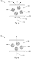
- FIGs 1a and 1b illustrate the light scattering properties of a PDLC film 100 in an off and on state respectively.
- Liquid crystals 104 are formed in droplets 102 held within a polymer matrix 106 which is itself contained between outer surfaces 108.
- Liquid crystals 104 are birefringent with a refractive index that is dependent on the orientation of the liquid crystal molecules. Under an applied electric field, the liquid crystal molecules 104 re-orient.
- the refractive index of the polymer binder 106 is matched to one refractive index of the liquid crystal 104 in a particular orientation.
- no external electric field is applied to the film 100, i.e. it is in an off state.
- the orientation of the liquid crystal 104 within droplets 102 is random meaning that there is a refractive index mismatch between the liquid crystal 104 and the surrounding polymer binder 106.
- This refractive index mismatch results in scattering of the incident light 110 to produce scattered light 112 both at the front and rear surfaces of the PDLC film 100. If the amount of scattering is sufficient then the PDLC film 100 can appear opaque in the off state.
- Figure 1b shows the PDLC film 100 under an applied electric field, i.e. in the on state. In this state the liquid crystals 104 orient themselves with the applied electric field such that the there is no refractive index mismatch between the liquid crystals 104 and the surrounding polymer binder 106.
- a PDLC film may also be switched optically (e.g. by incident sunlight) using materials that undergo photoisomerization resulting in a change in the refractive index properties.
- Drop-on-demand (DoD) inkjet printing is a fabrication process that allows for small droplets of a fluid to be deposited at well-defined, localized, locations on a substrate.
- DoD inkjet printing (or alternatively also a continuous inkjet printing process or other droplet-based inkjet process) is a suitable platform for the manufacture of PDLC films.
- Figure 2 illustrates schematically an apparatus 200 used to manufacture PDLC films by DoD inkjet printing according to the present invention.
- a print head 202 deposits LC droplets onto a region of a liquid, UV-curable polymer 206.
- the region may be a substantially uniform layer or a droplet of UV-curable polymer.
- a syringe pump 204 is used to supply the LC to the print head 202.
- a first heating unit 208 is used to heat the print head 202 and a second heating unit 210 is used to heat a substrate 212 on which the layer of polymer 206 is situated.
- LC droplets 214 are formed at the nozzle 216 of the print head 202, from where they are emitted and impact with the polymer 206. Accurate positioning of the droplet may be achieved using an x-y motorized stage 224 arranged to move the substrate/polymer layer relative to the print head 202. An ultraviolet light source 226 is used to photocure the polymer 206 containing the deposited LC droplets 214. In this manner phase separation between the polymer 206 and LC droplets 214 is induced by photo-polymerization.
- FIGS 3a to 3c Three process steps for forming a PDLC film according to an embodiment of the invention are illustrated in Figures 3a to 3c .
- the uncured polymer 206 is drop casted onto a channel formed on the substrate 212, e.g. with walls 232 at the edges of the substrate to contain the liquid polymer 206.
- the LC droplets 214 are printed onto the uncured liquid polymer 206 in the manner described above.
- UV radiation 234 is applied to perform photo-curing of the sample resulting in PDLC pixels 236 which are phase separated from the surrounding, cured polymer - thereby producing a PDLC film.
- the print head 202 used was a MJ-ABP-01-120 dispenser (Microfab Technologies Inc.) with a 120 ⁇ m nozzle diameter.
- the nematic LC chosen was the commercial nematic mixture, BL006 (Merck KGaA), which was supplied to the dispenser/print head 202 via a static pressure syringe pump 204.
- the thiolene-based optical adhesive NOA65 (Norland Products inc.), which involves a step-growth polymerization process, was selected as the UV-curable polymer binder 206.
- This nematic LC and UV-curable polymer combination was chosen because the ordinary refractive index (n o ) of BL006 is roughly matched to the refractive index of the polymer binder (n p ) ⁇ 1.52.
- LCs and UV-curable and thermal-curable polymers may be selected without departing from the invention.
- Two heating units 208 and 210 with 20W heating elements (DBK-HPOS, DBK Enclosures) and K-type thermocouples were used to control both the print-head 202 and printing substrate 212 temperatures to within 1°C of accuracy.
- drop 214 formation at the nozzle 216 as well as the subsequent impact onto the substrate was captured using a combination of a high-speed camera 218 (Phantom V12.1) and a halogen high-intensity white light source 220 (OSL2 3200K, Thorlabs), which was directed through a UV filter 222 and arranged in a shadowgraphy configuration.
- a high-speed camera 218 Pantom V12.1
- OSL2 3200K halogen high-intensity white light source 220
- the samples were photo-cured using a high-powered UV LED 226 (Thorlabs, CS2010 UV high power UV curing LED system) held at a fixed distance of 50 mm above the sample.
- the UV curing duration, power, temperature and time delay after printing were altered to investigate the effects on the resulting PDLC film. Timing synchronization, temperature control and droplet positioning, speed and volume were controlled using a purpose-built LabVIEW program in combination with a computer-controlled DAQ card 228 (NI USB-6351, National Instruments).
- the temperature of the print head was maintained at 65°C, since at this temperature the viscosity of the LC was sufficiently reduced to deposit via printing.
- other print head temperatures may also be suitable.
- a square-wave voltage pulse of 55V was supplied to the print head by an amplifier 230 in order to generate a single well-defined LC droplet (via push-mode, DoD) without the formation of satellite droplets.
- the resulting droplet velocity which was determined from the analysis of the high-speed images, was found to be 0.9 ⁇ 0.1ms -1 .
- the diameter of the droplets produced was slightly less than the nozzle diameter, ranging between 100-110 ⁇ m.
- the substrate 212 was prepared by first applying a spacer to the microscope slides to form 70 ⁇ m-thick 'walls' (using one or two layers) at the edges of the substrates. However, it should be appreciated that depending on the application the walls may have different heights/thicknesses or may not be required at all.
- the uncured polymer binder was then drop casted onto the channel that had been formed and coated using doctor blading to form a film of even thickness.
- the temperature of the substrate was controlled to within 20-70°C using heater 210.
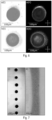
- FIG. 4 shows high-speed images of a droplet of the nematic LC, BL006, impacting the polymer binder, NOA65, according to one example.
- panel a) Shows an LC droplet printed at 65°C impacting the 70 ⁇ m-thick photo-curable polymer layer that was held at a temperature of 22°C by means of the substrate heater described above.
- Panel b) of Figure 4 shows the subsequent polarized microscopy image of the photocured polymer-LC sample captured after deposition and the photopolymerization process. The image shows that the LC did not fully dissolve into the polymer binder nor did extensive phase separation occur during the photopolymerization process.
- the centre of the image in panel b) of Figure 4 shows a pure LC region with a horizontal width of 220 ⁇ m.
- the area of this domain is comparatively large with respect to the printed droplet and in addition to the high-speed images, indicates that a portion of the LC may have spread on top of the polymer film without dissolving fully into the polymer binder prior to photopolymerization. This was confirmed experimentally, since upon gentle agitation of this central region with a cotton bud, the LC domain was easily disturbed, i.e. it is situated at the surface.
- the presence of small PDLC droplets, particularly around the fringes of the main body of the droplet indicates that a degree of mixing and photo-induced phase separation has occurred.
- the sample was thermally cured for 4 hours at 70°C and then re-examined using polarized microscopy. There was no identifiable difference between the images taken before and after thermal curing, indicating the sample had undergone near complete photopolymerization without necessarily requiring any further curing, e.g. by thermal means. Therefore, it should be appreciated that subsequent thermal curing of the sample is not essential to the formation of PDLC films according to the invention. However, a post UV or thermal process may be beneficial to ensure that the polymer is fully cross-linked.
- the actuation voltage of the print head was increased to 80V, resulting in a droplet velocity of 1.6ms -1 ⁇ 0.1ms -1 .
- the increased velocity did not appear to yield any observable improvements to the miscibility of the LC and polymer when the photo-curable layer was held at a temperature of 22°C.
- the temperature of the substrate 212 was increased further by means of the heater 210.
- Panel c) of Figure 4 shows the impact between a LC droplet, printed at 65°C, with a photo-curable polymer layer held at 55°C.
- the LC droplets within this region are polydisperse, with diameters ranging from approximately 1 to 8 ⁇ m.
- the full encapsulation of the LC domains was confirmed by agitating the polymer surface with no change in the LC droplets observed.
- the size of the LC droplets in the region are still typically too large, and the density of the domains too low, to efficiently scatter visible light.
- the macroscopic director within the nematic LC droplets is randomly oriented, with no correlation of the macroscopic preferential orientation across different LC domains.
- n o one component of the refractive index of the nematic LC
- n p the refractive index of the polymer
- incident light experiences a refractive index mismatch on propagating through the LC droplets and polymer binder.
- Figure 5 results in the scattering of light as it passes through the film, where the same reference numerals as Figures 1a and 1b have been adopted for like features.
- the LC domain size should preferably be slightly larger than the wavelength of the incident light.
- the size of the LC domains in a PDLC film are primarily determined by the UV curing intensity, duration of exposure to UV light, curing temperature, nematic LC concentration, and the physical properties of the LC and polymer phases such as the elastic coefficients, interfacial tension and viscosity.
- the delay between the deposition of the droplet and photo-polymerization process is a further parameter which influences the size of the LC domains. In general, increasing the UV curing intensity and/or curing temperature increases the rate at which polymerization occurs, resulting in smaller LC domains.
- panels a)i) and a)ii) show the resulting microscopy and polarized microscopy images of a printed PDLC element, which was formed by printing the nematic LC, BL006, onto a 70 ⁇ m-thick wet polymer substrate (NOA65) and photo-cured when the sample was held at the higher temperature of 65°C with a UV light intensity of 40 mW/m 2 for 4 minutes.
- the initial delay between printing and curing was 1 second.
- volume fraction of LC to photopolymer of the PDLC pixel can be estimated by comparing the volume of the printed LC droplet to that of a cylinder with a diameter equal to that of the high-density regime and a height equal to that of the photo-polymer (NOA65) layer. For a droplet diameter of 100 ⁇ m, this gives a volume fraction of 66% LC to photopolymer, which is consistent with typical fractions used for PDLC light-scattering applications.
- the area of the high-density central regime is of a comparable size to that of the previous sample, with a diameter of 120 ⁇ m.
- the results suggest that the majority of the LC is effectively pinned to an area close to that of the maximum area of the droplet as it initially spreads on top of the photopolymer (NOA65) layer during droplet impact. It is suspected that the mobility of the LC molecules is hindered due to the large, high molecular weight polymer chains of the photopolymer.
- the increased substrate temperature should increase the mobility of the LC molecules, it may in fact also initiate partial cross-linking of the photopolymer, thereby further impeding the mobility of the LC molecules.
- inkjet printing makes it possible to form arrays of pixels as shown in Figure 7 panel c).
- the line array was printed with the wet photopolymer layer held at a temperature of 65°C, e.g. by substrate heater 210. After a 10s delay, the sample was then cured at 65°C using a UV-light source with a power density of 185 mW/m 2 at the exit of the source, which was held at a distance of 2 cm from the sample.
- the printed line seen in Figure 7 panel d) was deposited by supplying the print head with a step-input voltage pulse. This results in an extended fluid ligament, which combined with translation of the printing substrate, results in the ability to print lines. Additionally, line geometries could also be produced by printing LC droplets close to each other. Tests have been carried out using smaller nozzles printing, with results indicating that feature sizes at least as small as 15 ⁇ m could be produced.
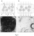
- the LC molecules In order for the PDLC pixels to switch from an OFF, scattering state, shown in Figure 8 panel a), to an ON, non-scattering state, shown in Figure 8 panel b), the LC molecules should be able to re-orient under the application of an electric field. When the LC molecules orient parallel to an applied electric field, incident light will experience only the ordinary component of the LC refractive index, n o. Since this is matched to the refractive index of the cured photopolymer, n p , the incident light is then not scattered by the sample as shown in Figure 8 panel b).
- the films were carefully peeled away from the printing substrate using a scalpel and sandwiched between ITO-coated glass. To ensure a constant cell gap of 70 ⁇ m, spacer tape was used around the perimeter of the cell and optical glue was then used to bind the substrates together.
- Panels c) and d) in Figure 8 show optical microscopy images of a single PDLC pixel in the off/dark state and on/transparent state, respectively.
- a photo-diode 908 (PDA36A-EC, Thorlabs) was then positioned at an angle of 8° from the laser beam propagation direction so as to measure the forward off-axis scattered light.
- Figure 10 shows the effective transmission of the PDLC pixel as the voltage is increased. As seen, the PDLC pixel effectively changes from a dark to transparent state under application of the external electric field.
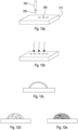
- FIGS 11a to 11c Three process steps for forming a PDLC film not according to the invention are illustrated in Figures 11a to 11c .
- a premixed formulation 250 composed of an LC formulation and a UV-curable polymer is printed using a print head 202 directly onto a substrate 212, Figure 11a .
- the inkjet printing is arranged to directly print a film 252 onto the substrate. This is achieved by arranging the printing substrate and printing conditions so as to encourage full wetting of the printing substrate 212. After deposition of the thin film 252 it is irradiated with UV light in a similar manner as described above, Figure 11b .
- a PDLC film is manufactured by inkjet printing a pre-mixed formulation of LC and UV-curable polymer in one step, rather than first providing a liquid, UV-curable polymer layer and subsequently adding the LC formulations.
- the PDLC film manufactured according to the method described with reference to Figures 11a to 11c is essentially homogenous, in that it does not contain discrete PDLC pixels as described previously.
- the printing substrate and printing conditions can be arranged to encourage the pre-mixed LC formulation and UV-curable polymer to form sessile droplets on the surface of the substrate.
- This is illustrated in Figures 12a to 12c .
- a premixed formulation 250 composed of an LC formulation and a UV-curable polymer is printed using a print head 202 directly onto a substrate 212, Figure 12a . This results in a number of discrete sessile droplets 256 of LC formulation and UV-curable polymer on the surface on the substrate.
- the UV-curing may result in either an encapsulated LC droplet, Figure 12c , a PDLC droplet with micron-sized domains, Figure 12d , or a PDLC droplet with nano-sized domains, Figure 12d .
Landscapes
- Physics & Mathematics (AREA)
- Nonlinear Science (AREA)
- Chemical & Material Sciences (AREA)
- Mathematical Physics (AREA)
- Crystallography & Structural Chemistry (AREA)
- General Physics & Mathematics (AREA)
- Optics & Photonics (AREA)
- Dispersion Chemistry (AREA)
- Liquid Crystal (AREA)
- Application Of Or Painting With Fluid Materials (AREA)
Claims (15)
- Verfahren zur Herstellung eines Polymerdispergierter-Flüssigkristall(PDLC)-Films (100), wobei das Verfahren umfasst:Bilden eines Bereichs von flüssigem Polymer (206) auf einem Substrat (212);Abscheiden einer oder mehrerer Flüssigkristall(LC)-Formulierungen (214) in das flüssige Polymer (206); undanschließend Härten des flüssigen Polymers (206), um Phasentrennung zwischen dem Polymer (206) und den Flüssigkristallformulierungen (214) zu induzieren.
- Verfahren gemäß Anspruch 1, wobei Härten und Phasentrennung wenigstens zum Teil durch Photopolymerisation durchgeführt werden.
- Verfahren gemäß einem der vorstehenden Ansprüche, wobei Härten und Phasentrennung wenigstens zum Teil durch Wärmehärten durchgeführt werden.
- Verfahren gemäß einem der vorstehenden Ansprüche, wobei der Schritt des Abscheidens einer oder mehrerer Flüssigkristallformulierungen (214) Tintenstrahldrucken von Flüssigkristalltröpfchen (214) aus einem Druckkopf (202) in das flüssige Polymer (206) umfasst.
- Verfahren gemäß Anspruch 4, wobei das Tintenstrahldruckverfahren ein Drop-on-Demand-Tintenstrahldruckverfahren, ein kontinuierliches Tintenstrahldruckverfahren oder ein elektrohydrodynamisches Strahldruckverfahren ist.
- Verfahren gemäß einem der vorstehenden Ansprüche, wobei der Bereich von flüssigem Polymer (206) eine Schicht von flüssigem Polymer (206) oder alternativ ein Tröpfchen von flüssigem Polymer (206) ist.
- Verfahren gemäß einem der vorstehenden Ansprüche, wobei das flüssige Polymer (206) ein optischer Klebstoff auf Thiolenbasis ist.
- Verfahren gemäß einem der vorstehenden Ansprüche, wobei ein Brechungsindex des flüssigen Polymers (206) ausgewählt ist, um einem Brechungsindex der Flüssigkristallformulierungen (214) zu entsprechen.
- Verfahren gemäß einem der vorstehenden Ansprüche, ferner umfassend den Schritt des Überwachens des Bildens und der Abscheidung der Flüssigkristallformulierungen (214) unter Verwendung einer Videokamera (218), gegebenenfalls in einer Schattenabbildungskonfiguration.
- Verfahren gemäß einem der Ansprüche 2 bis 9, ferner umfassend:i) Durchführen von Wärmehärtung nach Photopolymerisation; und/oderii) Anlegen eines externen elektrischen Felds an das Substrat während des Schritts der Photopolymerisation.
- Verfahren gemäß einem der vorstehenden Ansprüche, ferner umfassend Positionieren eines oberen Substrats über dem Polymer (206) nach dem Schritt des Härtens.
- Verfahren gemäß einem der vorstehenden Ansprüche, ferner umfassend, nach dem Schritt des Härtens, Beschichten des Bereichs von Polymer (206) mit einem leitfähigen Polymer und gegebenenfalls Anbringen von Elektroden an dem leitfähigen Polymer.
- Verfahren gemäß einem der vorstehenden Ansprüche, wobei der Bereich von flüssigem Polymer (206) durch ein Dünnfilmabscheidungsverfahren oder Tintenstrahldruckverfahren abgeschieden wird.
- Verfahren gemäß einem der vorstehenden Ansprüche, wobei die LC-Formulierungen (206) eines oder mehrere von folgendem umfassen:nematische Flüssigkristalle;chirale nematische Flüssigkristalle;smektische Flüssigkristalle;Blauphasen-Flüssigkristalle; und/oderreaktionsfähige Mesogene.
- Verfahren gemäß einem der vorstehenden Ansprüche, wobei die LC-Formulierungen (206) ferner eines oder mehrere von folgendem umfassen:einen oder mehrere Farbstoffe;zusätzliche Partikel zum Erhöhen der Lichtstreuungseigenschaften;ionische Dotierstoffe; und/oderTenside zum Verbessern der Druckbarkeit der LC-Formulierungen.
Applications Claiming Priority (2)
| Application Number | Priority Date | Filing Date | Title |
|---|---|---|---|
| GBGB1819634.5A GB201819634D0 (en) | 2018-11-30 | 2018-11-30 | Polymer dispersed liquid crystals |
| PCT/GB2019/053323 WO2020109763A1 (en) | 2018-11-30 | 2019-11-26 | Methods of manufacturing polymer dispersed liquid crystal films |
Publications (2)
| Publication Number | Publication Date |
|---|---|
| EP3887899A1 EP3887899A1 (de) | 2021-10-06 |
| EP3887899B1 true EP3887899B1 (de) | 2024-05-29 |
Family
ID=65024877
Family Applications (1)
| Application Number | Title | Priority Date | Filing Date |
|---|---|---|---|
| EP19816393.3A Active EP3887899B1 (de) | 2018-11-30 | 2019-11-26 | Verfahren zur herstellung von dispergierten polymerflüssigkristallfilmen |
Country Status (4)
| Country | Link |
|---|---|
| US (1) | US11500238B2 (de) |
| EP (1) | EP3887899B1 (de) |
| GB (1) | GB201819634D0 (de) |
| WO (1) | WO2020109763A1 (de) |
Families Citing this family (1)
| Publication number | Priority date | Publication date | Assignee | Title |
|---|---|---|---|---|
| EP4318112A4 (de) * | 2021-03-30 | 2025-03-26 | Nitto Denko Corporation | Polymerdispergierte flüssigkristallfolie und herstellungsverfahren dafür |
Family Cites Families (14)
| Publication number | Priority date | Publication date | Assignee | Title |
|---|---|---|---|---|
| US6104448A (en) * | 1991-05-02 | 2000-08-15 | Kent State University | Pressure sensitive liquid crystalline light modulating device and material |
| JP3455091B2 (ja) | 1997-11-11 | 2003-10-06 | 株式会社東芝 | 液晶表示素子及びその製造方法 |
| JP2000122042A (ja) | 1998-10-20 | 2000-04-28 | Matsushita Electric Ind Co Ltd | 液晶表示素子及びその製造方法 |
| KR100653471B1 (ko) | 2003-03-31 | 2006-12-04 | 비오이 하이디스 테크놀로지 주식회사 | 컬러 고분자 분산 액정표시장치 및 그 제조방법 |
| GB0319908D0 (en) * | 2003-08-23 | 2003-09-24 | Koninkl Philips Electronics Nv | Method of producing an electronic device, electronic device and apparatus for implementing the method |
| WO2008110316A1 (en) | 2007-03-13 | 2008-09-18 | Technische Universitei Eindhoven | Polarization selective scattering security device and method for manufacturing the same |
| CN101373286B (zh) | 2007-08-22 | 2010-12-08 | 比亚迪股份有限公司 | 一种聚合物分散液晶薄膜的制备方法 |
| KR102011913B1 (ko) * | 2012-11-19 | 2019-08-20 | 삼성디스플레이 주식회사 | 잉크젯 장치 |
| US10031364B2 (en) * | 2013-06-25 | 2018-07-24 | Kent State University | Polymer-dispersed blue-phase liquid crystal films |
| KR20150083742A (ko) * | 2014-01-10 | 2015-07-20 | 삼성전자주식회사 | 디스플레이 장치 및 이의 제조방법 |
| US10520787B2 (en) * | 2016-11-21 | 2019-12-31 | Gopro, Inc. | Tunable polymer dispersed liquid crystal grin lens |
| KR102549136B1 (ko) * | 2017-12-22 | 2023-06-30 | 삼성전자주식회사 | 디스플레이 장치 및 그 제어 방법 |
| US20210208450A1 (en) * | 2018-09-18 | 2021-07-08 | Hewlett-Packard Development Company, L.P. | Privacy films for electronic displays |
| CN111983863B (zh) * | 2019-05-24 | 2025-08-26 | 北京京东方晟视科技有限公司 | 调光玻璃 |
-
2018
- 2018-11-30 GB GBGB1819634.5A patent/GB201819634D0/en not_active Ceased
-
2019
- 2019-11-26 US US17/296,285 patent/US11500238B2/en active Active
- 2019-11-26 WO PCT/GB2019/053323 patent/WO2020109763A1/en not_active Ceased
- 2019-11-26 EP EP19816393.3A patent/EP3887899B1/de active Active
Also Published As
| Publication number | Publication date |
|---|---|
| EP3887899A1 (de) | 2021-10-06 |
| US20220011609A1 (en) | 2022-01-13 |
| GB201819634D0 (en) | 2019-01-16 |
| US11500238B2 (en) | 2022-11-15 |
| WO2020109763A1 (en) | 2020-06-04 |
Similar Documents
| Publication | Publication Date | Title |
|---|---|---|
| Kamal et al. | Spatially patterned polymer dispersed liquid crystals for image‐integrated smart windows | |
| KR101063919B1 (ko) | 위상차 판의 제조 방법 | |
| TWI297089B (en) | A composition for the preparation of microcups used in a liquid crystal display, a liquid crystal display comprising two or more layers of microcup array and process for its manufacture | |
| JP5890390B2 (ja) | ポリマ安定化型サーモトロピック液晶デバイス | |
| JP4720946B2 (ja) | 3次元ディスプレイの位相差板に用いられる凹凸基材の製造方法 | |
| KR20020079602A (ko) | 액정 조성물, 컬러필터 및 액정표시장치 | |
| De Sio et al. | Composite Holographic Gratings Containing Light‐Responsive Liquid Crystals for Visible Bichromatic Switching | |
| Dogra et al. | Evaporation induced self-assembly of silica nanoparticles on ITO substrates in a confined cell for vertical alignment of liquid crystals and performance analysis | |
| CN104777651A (zh) | 一种胆甾相液晶光栅图案聚合方法 | |
| US11500238B2 (en) | Methods of manufacturing polymer dispersed liquid crystal films | |
| WO2015010429A1 (zh) | 一种液晶显示面板的制备方法 | |
| US20210046586A1 (en) | Additive manufacturing systems and methods | |
| Ma et al. | Advanced Image‐Integrated Smart Windows using Printed Electrochromic Polymer‐Dispersed Liquid Crystal Droplets | |
| US11581691B2 (en) | All-optical, optically addressable liquid crystal-based light valve employing photoswitchable alignment layer for high-power and/or large aperture laser applications | |
| Pagidi et al. | Reduced driving electric field of ionic salt doped nano-structured polymer dispersed liquid crystals device | |
| Boniello et al. | Making Smectic Defect Patterns Electrically Reversible and Dynamically Tunable Using In Situ Polymer‐Templated Nematic Liquid Crystals | |
| CN102702548A (zh) | 一种含孔聚合物分散液晶薄膜的制备方法及性能测试装置 | |
| Pikas et al. | Electrically switchable reflection holograms formed using two-photon photopolymerization | |
| Kim et al. | Effect of cell gap on electro-optical properties of polymer dispersed liquid crystal lens for smart electronic glasses | |
| JP2009300844A (ja) | 液晶表示パネルの製造方法 | |
| Marinov et al. | Single‐layered microscale linear‐gradient PDLC material for electro‐optics | |
| Tatipamula et al. | Electro-Optical properties of photoaligned Liquid Crystal cells prepared with obliquely irradiated Chalcogenide glasses | |
| CN106597702A (zh) | 液晶装置的制造方法与由此方法所制造出的液晶装置 | |
| Shimamura et al. | Photoinduced bending upon pulsed irradiation in azobenzene-containing crosslinked liquid-crystalline polymers | |
| Bella et al. | Phase separation and image recording in UV laser cured PDLC |
Legal Events
| Date | Code | Title | Description |
|---|---|---|---|
| STAA | Information on the status of an ep patent application or granted ep patent |
Free format text: STATUS: UNKNOWN |
|
| STAA | Information on the status of an ep patent application or granted ep patent |
Free format text: STATUS: THE INTERNATIONAL PUBLICATION HAS BEEN MADE |
|
| PUAI | Public reference made under article 153(3) epc to a published international application that has entered the european phase |
Free format text: ORIGINAL CODE: 0009012 |
|
| STAA | Information on the status of an ep patent application or granted ep patent |
Free format text: STATUS: REQUEST FOR EXAMINATION WAS MADE |
|
| 17P | Request for examination filed |
Effective date: 20210630 |
|
| AK | Designated contracting states |
Kind code of ref document: A1 Designated state(s): AL AT BE BG CH CY CZ DE DK EE ES FI FR GB GR HR HU IE IS IT LI LT LU LV MC MK MT NL NO PL PT RO RS SE SI SK SM TR |
|
| DAV | Request for validation of the european patent (deleted) | ||
| DAX | Request for extension of the european patent (deleted) | ||
| GRAP | Despatch of communication of intention to grant a patent |
Free format text: ORIGINAL CODE: EPIDOSNIGR1 |
|
| STAA | Information on the status of an ep patent application or granted ep patent |
Free format text: STATUS: GRANT OF PATENT IS INTENDED |
|
| INTG | Intention to grant announced |
Effective date: 20231222 |
|
| GRAS | Grant fee paid |
Free format text: ORIGINAL CODE: EPIDOSNIGR3 |
|
| GRAA | (expected) grant |
Free format text: ORIGINAL CODE: 0009210 |
|
| STAA | Information on the status of an ep patent application or granted ep patent |
Free format text: STATUS: THE PATENT HAS BEEN GRANTED |
|
| AK | Designated contracting states |
Kind code of ref document: B1 Designated state(s): AL AT BE BG CH CY CZ DE DK EE ES FI FR GB GR HR HU IE IS IT LI LT LU LV MC MK MT NL NO PL PT RO RS SE SI SK SM TR |
|
| REG | Reference to a national code |
Ref country code: CH Ref legal event code: EP |
|
| REG | Reference to a national code |
Ref country code: IE Ref legal event code: FG4D |
|
| REG | Reference to a national code |
Ref country code: DE Ref legal event code: R096 Ref document number: 602019053016 Country of ref document: DE |
|
| REG | Reference to a national code |
Ref country code: LT Ref legal event code: MG9D |
|
| REG | Reference to a national code |
Ref country code: NL Ref legal event code: MP Effective date: 20240529 |
|
| PG25 | Lapsed in a contracting state [announced via postgrant information from national office to epo] |
Ref country code: IS Free format text: LAPSE BECAUSE OF FAILURE TO SUBMIT A TRANSLATION OF THE DESCRIPTION OR TO PAY THE FEE WITHIN THE PRESCRIBED TIME-LIMIT Effective date: 20240929 |
|
| PG25 | Lapsed in a contracting state [announced via postgrant information from national office to epo] |
Ref country code: BG Free format text: LAPSE BECAUSE OF FAILURE TO SUBMIT A TRANSLATION OF THE DESCRIPTION OR TO PAY THE FEE WITHIN THE PRESCRIBED TIME-LIMIT Effective date: 20240529 |
|
| PG25 | Lapsed in a contracting state [announced via postgrant information from national office to epo] |
Ref country code: HR Free format text: LAPSE BECAUSE OF FAILURE TO SUBMIT A TRANSLATION OF THE DESCRIPTION OR TO PAY THE FEE WITHIN THE PRESCRIBED TIME-LIMIT Effective date: 20240529 Ref country code: FI Free format text: LAPSE BECAUSE OF FAILURE TO SUBMIT A TRANSLATION OF THE DESCRIPTION OR TO PAY THE FEE WITHIN THE PRESCRIBED TIME-LIMIT Effective date: 20240529 |
|
| PG25 | Lapsed in a contracting state [announced via postgrant information from national office to epo] |
Ref country code: GR Free format text: LAPSE BECAUSE OF FAILURE TO SUBMIT A TRANSLATION OF THE DESCRIPTION OR TO PAY THE FEE WITHIN THE PRESCRIBED TIME-LIMIT Effective date: 20240830 |
|
| REG | Reference to a national code |
Ref country code: AT Ref legal event code: MK05 Ref document number: 1691136 Country of ref document: AT Kind code of ref document: T Effective date: 20240529 |
|
| PG25 | Lapsed in a contracting state [announced via postgrant information from national office to epo] |
Ref country code: ES Free format text: LAPSE BECAUSE OF FAILURE TO SUBMIT A TRANSLATION OF THE DESCRIPTION OR TO PAY THE FEE WITHIN THE PRESCRIBED TIME-LIMIT Effective date: 20240529 |
|
| PG25 | Lapsed in a contracting state [announced via postgrant information from national office to epo] |
Ref country code: AT Free format text: LAPSE BECAUSE OF FAILURE TO SUBMIT A TRANSLATION OF THE DESCRIPTION OR TO PAY THE FEE WITHIN THE PRESCRIBED TIME-LIMIT Effective date: 20240529 |
|
| PG25 | Lapsed in a contracting state [announced via postgrant information from national office to epo] |
Ref country code: PL Free format text: LAPSE BECAUSE OF FAILURE TO SUBMIT A TRANSLATION OF THE DESCRIPTION OR TO PAY THE FEE WITHIN THE PRESCRIBED TIME-LIMIT Effective date: 20240529 |
|
| PG25 | Lapsed in a contracting state [announced via postgrant information from national office to epo] |
Ref country code: LV Free format text: LAPSE BECAUSE OF FAILURE TO SUBMIT A TRANSLATION OF THE DESCRIPTION OR TO PAY THE FEE WITHIN THE PRESCRIBED TIME-LIMIT Effective date: 20240529 |
|
| PG25 | Lapsed in a contracting state [announced via postgrant information from national office to epo] |
Ref country code: PL Free format text: LAPSE BECAUSE OF FAILURE TO SUBMIT A TRANSLATION OF THE DESCRIPTION OR TO PAY THE FEE WITHIN THE PRESCRIBED TIME-LIMIT Effective date: 20240529 Ref country code: NO Free format text: LAPSE BECAUSE OF FAILURE TO SUBMIT A TRANSLATION OF THE DESCRIPTION OR TO PAY THE FEE WITHIN THE PRESCRIBED TIME-LIMIT Effective date: 20240829 Ref country code: LV Free format text: LAPSE BECAUSE OF FAILURE TO SUBMIT A TRANSLATION OF THE DESCRIPTION OR TO PAY THE FEE WITHIN THE PRESCRIBED TIME-LIMIT Effective date: 20240529 Ref country code: IS Free format text: LAPSE BECAUSE OF FAILURE TO SUBMIT A TRANSLATION OF THE DESCRIPTION OR TO PAY THE FEE WITHIN THE PRESCRIBED TIME-LIMIT Effective date: 20240929 Ref country code: HR Free format text: LAPSE BECAUSE OF FAILURE TO SUBMIT A TRANSLATION OF THE DESCRIPTION OR TO PAY THE FEE WITHIN THE PRESCRIBED TIME-LIMIT Effective date: 20240529 Ref country code: GR Free format text: LAPSE BECAUSE OF FAILURE TO SUBMIT A TRANSLATION OF THE DESCRIPTION OR TO PAY THE FEE WITHIN THE PRESCRIBED TIME-LIMIT Effective date: 20240830 Ref country code: FI Free format text: LAPSE BECAUSE OF FAILURE TO SUBMIT A TRANSLATION OF THE DESCRIPTION OR TO PAY THE FEE WITHIN THE PRESCRIBED TIME-LIMIT Effective date: 20240529 Ref country code: ES Free format text: LAPSE BECAUSE OF FAILURE TO SUBMIT A TRANSLATION OF THE DESCRIPTION OR TO PAY THE FEE WITHIN THE PRESCRIBED TIME-LIMIT Effective date: 20240529 Ref country code: BG Free format text: LAPSE BECAUSE OF FAILURE TO SUBMIT A TRANSLATION OF THE DESCRIPTION OR TO PAY THE FEE WITHIN THE PRESCRIBED TIME-LIMIT Effective date: 20240529 Ref country code: AT Free format text: LAPSE BECAUSE OF FAILURE TO SUBMIT A TRANSLATION OF THE DESCRIPTION OR TO PAY THE FEE WITHIN THE PRESCRIBED TIME-LIMIT Effective date: 20240529 Ref country code: RS Free format text: LAPSE BECAUSE OF FAILURE TO SUBMIT A TRANSLATION OF THE DESCRIPTION OR TO PAY THE FEE WITHIN THE PRESCRIBED TIME-LIMIT Effective date: 20240829 |
|
| PG25 | Lapsed in a contracting state [announced via postgrant information from national office to epo] |
Ref country code: NL Free format text: LAPSE BECAUSE OF FAILURE TO SUBMIT A TRANSLATION OF THE DESCRIPTION OR TO PAY THE FEE WITHIN THE PRESCRIBED TIME-LIMIT Effective date: 20240529 |
|
| PG25 | Lapsed in a contracting state [announced via postgrant information from national office to epo] |
Ref country code: NL Free format text: LAPSE BECAUSE OF FAILURE TO SUBMIT A TRANSLATION OF THE DESCRIPTION OR TO PAY THE FEE WITHIN THE PRESCRIBED TIME-LIMIT Effective date: 20240529 |
|
| PG25 | Lapsed in a contracting state [announced via postgrant information from national office to epo] |
Ref country code: DK Free format text: LAPSE BECAUSE OF FAILURE TO SUBMIT A TRANSLATION OF THE DESCRIPTION OR TO PAY THE FEE WITHIN THE PRESCRIBED TIME-LIMIT Effective date: 20240529 |
|
| PG25 | Lapsed in a contracting state [announced via postgrant information from national office to epo] |
Ref country code: EE Free format text: LAPSE BECAUSE OF FAILURE TO SUBMIT A TRANSLATION OF THE DESCRIPTION OR TO PAY THE FEE WITHIN THE PRESCRIBED TIME-LIMIT Effective date: 20240529 |
|
| PG25 | Lapsed in a contracting state [announced via postgrant information from national office to epo] |
Ref country code: CZ Free format text: LAPSE BECAUSE OF FAILURE TO SUBMIT A TRANSLATION OF THE DESCRIPTION OR TO PAY THE FEE WITHIN THE PRESCRIBED TIME-LIMIT Effective date: 20240529 |
|
| PG25 | Lapsed in a contracting state [announced via postgrant information from national office to epo] |
Ref country code: SK Free format text: LAPSE BECAUSE OF FAILURE TO SUBMIT A TRANSLATION OF THE DESCRIPTION OR TO PAY THE FEE WITHIN THE PRESCRIBED TIME-LIMIT Effective date: 20240529 Ref country code: RO Free format text: LAPSE BECAUSE OF FAILURE TO SUBMIT A TRANSLATION OF THE DESCRIPTION OR TO PAY THE FEE WITHIN THE PRESCRIBED TIME-LIMIT Effective date: 20240529 |
|
| PG25 | Lapsed in a contracting state [announced via postgrant information from national office to epo] |
Ref country code: SM Free format text: LAPSE BECAUSE OF FAILURE TO SUBMIT A TRANSLATION OF THE DESCRIPTION OR TO PAY THE FEE WITHIN THE PRESCRIBED TIME-LIMIT Effective date: 20240529 |
|
| PG25 | Lapsed in a contracting state [announced via postgrant information from national office to epo] |
Ref country code: SM Free format text: LAPSE BECAUSE OF FAILURE TO SUBMIT A TRANSLATION OF THE DESCRIPTION OR TO PAY THE FEE WITHIN THE PRESCRIBED TIME-LIMIT Effective date: 20240529 Ref country code: SK Free format text: LAPSE BECAUSE OF FAILURE TO SUBMIT A TRANSLATION OF THE DESCRIPTION OR TO PAY THE FEE WITHIN THE PRESCRIBED TIME-LIMIT Effective date: 20240529 Ref country code: RO Free format text: LAPSE BECAUSE OF FAILURE TO SUBMIT A TRANSLATION OF THE DESCRIPTION OR TO PAY THE FEE WITHIN THE PRESCRIBED TIME-LIMIT Effective date: 20240529 Ref country code: EE Free format text: LAPSE BECAUSE OF FAILURE TO SUBMIT A TRANSLATION OF THE DESCRIPTION OR TO PAY THE FEE WITHIN THE PRESCRIBED TIME-LIMIT Effective date: 20240529 Ref country code: DK Free format text: LAPSE BECAUSE OF FAILURE TO SUBMIT A TRANSLATION OF THE DESCRIPTION OR TO PAY THE FEE WITHIN THE PRESCRIBED TIME-LIMIT Effective date: 20240529 Ref country code: CZ Free format text: LAPSE BECAUSE OF FAILURE TO SUBMIT A TRANSLATION OF THE DESCRIPTION OR TO PAY THE FEE WITHIN THE PRESCRIBED TIME-LIMIT Effective date: 20240529 |
|
| PG25 | Lapsed in a contracting state [announced via postgrant information from national office to epo] |
Ref country code: IT Free format text: LAPSE BECAUSE OF FAILURE TO SUBMIT A TRANSLATION OF THE DESCRIPTION OR TO PAY THE FEE WITHIN THE PRESCRIBED TIME-LIMIT Effective date: 20240529 |
|
| REG | Reference to a national code |
Ref country code: DE Ref legal event code: R097 Ref document number: 602019053016 Country of ref document: DE |
|
| PLBE | No opposition filed within time limit |
Free format text: ORIGINAL CODE: 0009261 |
|
| STAA | Information on the status of an ep patent application or granted ep patent |
Free format text: STATUS: NO OPPOSITION FILED WITHIN TIME LIMIT |
|
| PG25 | Lapsed in a contracting state [announced via postgrant information from national office to epo] |
Ref country code: SI Free format text: LAPSE BECAUSE OF FAILURE TO SUBMIT A TRANSLATION OF THE DESCRIPTION OR TO PAY THE FEE WITHIN THE PRESCRIBED TIME-LIMIT Effective date: 20240529 |
|
| 26N | No opposition filed |
Effective date: 20250303 |
|
| REG | Reference to a national code |
Ref country code: DE Ref legal event code: R119 Ref document number: 602019053016 Country of ref document: DE |
|
| REG | Reference to a national code |
Ref country code: CH Ref legal event code: PL |
|
| PG25 | Lapsed in a contracting state [announced via postgrant information from national office to epo] |
Ref country code: MC Free format text: LAPSE BECAUSE OF FAILURE TO SUBMIT A TRANSLATION OF THE DESCRIPTION OR TO PAY THE FEE WITHIN THE PRESCRIBED TIME-LIMIT Effective date: 20240529 |
|
| PG25 | Lapsed in a contracting state [announced via postgrant information from national office to epo] |
Ref country code: LU Free format text: LAPSE BECAUSE OF NON-PAYMENT OF DUE FEES Effective date: 20241126 |
|
| REG | Reference to a national code |
Ref country code: CH Ref legal event code: PL |
|
| GBPC | Gb: european patent ceased through non-payment of renewal fee |
Effective date: 20241126 |
|
| PG25 | Lapsed in a contracting state [announced via postgrant information from national office to epo] |
Ref country code: CH Free format text: LAPSE BECAUSE OF NON-PAYMENT OF DUE FEES Effective date: 20241130 |
|
| REG | Reference to a national code |
Ref country code: BE Ref legal event code: MM Effective date: 20241130 |
|
| PG25 | Lapsed in a contracting state [announced via postgrant information from national office to epo] |
Ref country code: SE Free format text: LAPSE BECAUSE OF FAILURE TO SUBMIT A TRANSLATION OF THE DESCRIPTION OR TO PAY THE FEE WITHIN THE PRESCRIBED TIME-LIMIT Effective date: 20240529 |
|
| PG25 | Lapsed in a contracting state [announced via postgrant information from national office to epo] |
Ref country code: DE Free format text: LAPSE BECAUSE OF NON-PAYMENT OF DUE FEES Effective date: 20250603 |
|
| PG25 | Lapsed in a contracting state [announced via postgrant information from national office to epo] |
Ref country code: GB Free format text: LAPSE BECAUSE OF NON-PAYMENT OF DUE FEES Effective date: 20241126 Ref country code: BE Free format text: LAPSE BECAUSE OF NON-PAYMENT OF DUE FEES Effective date: 20241130 |
|
| PG25 | Lapsed in a contracting state [announced via postgrant information from national office to epo] |
Ref country code: FR Free format text: LAPSE BECAUSE OF NON-PAYMENT OF DUE FEES Effective date: 20241130 |
|
| PG25 | Lapsed in a contracting state [announced via postgrant information from national office to epo] |
Ref country code: IE Free format text: LAPSE BECAUSE OF NON-PAYMENT OF DUE FEES Effective date: 20241126 |
|
| PG25 | Lapsed in a contracting state [announced via postgrant information from national office to epo] |
Ref country code: PT Free format text: LAPSE BECAUSE OF NON-PAYMENT OF DUE FEES Effective date: 20240529 |
|
| PG25 | Lapsed in a contracting state [announced via postgrant information from national office to epo] |
Ref country code: HU Free format text: LAPSE BECAUSE OF FAILURE TO SUBMIT A TRANSLATION OF THE DESCRIPTION OR TO PAY THE FEE WITHIN THE PRESCRIBED TIME-LIMIT; INVALID AB INITIO Effective date: 20191126 |
|
| PG25 | Lapsed in a contracting state [announced via postgrant information from national office to epo] |
Ref country code: CY Free format text: LAPSE BECAUSE OF FAILURE TO SUBMIT A TRANSLATION OF THE DESCRIPTION OR TO PAY THE FEE WITHIN THE PRESCRIBED TIME-LIMIT; INVALID AB INITIO Effective date: 20191126 |