EP3887743B1 - Procédé de fabrication d'un échangeur thermique ou d'un caloduc - Google Patents
Procédé de fabrication d'un échangeur thermique ou d'un caloduc Download PDFInfo
- Publication number
- EP3887743B1 EP3887743B1 EP19805692.1A EP19805692A EP3887743B1 EP 3887743 B1 EP3887743 B1 EP 3887743B1 EP 19805692 A EP19805692 A EP 19805692A EP 3887743 B1 EP3887743 B1 EP 3887743B1
- Authority
- EP
- European Patent Office
- Prior art keywords
- assembly
- interstices
- manufacturing
- plates
- defining
- Prior art date
- Legal status (The legal status is an assumption and is not a legal conclusion. Google has not performed a legal analysis and makes no representation as to the accuracy of the status listed.)
- Not-in-force
Links
Images



Classifications
-
- F—MECHANICAL ENGINEERING; LIGHTING; HEATING; WEAPONS; BLASTING
- F28—HEAT EXCHANGE IN GENERAL
- F28D—HEAT-EXCHANGE APPARATUS, NOT PROVIDED FOR IN ANOTHER SUBCLASS, IN WHICH THE HEAT-EXCHANGE MEDIA DO NOT COME INTO DIRECT CONTACT
- F28D9/00—Heat-exchange apparatus having stationary plate-like or laminated conduit assemblies for both heat-exchange media, the media being in contact with different sides of a conduit wall
- F28D9/0025—Heat-exchange apparatus having stationary plate-like or laminated conduit assemblies for both heat-exchange media, the media being in contact with different sides of a conduit wall the conduits being formed by zig-zag bend plates
-
- C—CHEMISTRY; METALLURGY
- C25—ELECTROLYTIC OR ELECTROPHORETIC PROCESSES; APPARATUS THEREFOR
- C25D—PROCESSES FOR THE ELECTROLYTIC OR ELECTROPHORETIC PRODUCTION OF COATINGS; ELECTROFORMING; APPARATUS THEREFOR
- C25D1/00—Electroforming
-
- C—CHEMISTRY; METALLURGY
- C25—ELECTROLYTIC OR ELECTROPHORETIC PROCESSES; APPARATUS THEREFOR
- C25D—PROCESSES FOR THE ELECTROLYTIC OR ELECTROPHORETIC PRODUCTION OF COATINGS; ELECTROFORMING; APPARATUS THEREFOR
- C25D3/00—Electroplating: Baths therefor
- C25D3/02—Electroplating: Baths therefor from solutions
- C25D3/12—Electroplating: Baths therefor from solutions of nickel or cobalt
-
- C—CHEMISTRY; METALLURGY
- C25—ELECTROLYTIC OR ELECTROPHORETIC PROCESSES; APPARATUS THEREFOR
- C25D—PROCESSES FOR THE ELECTROLYTIC OR ELECTROPHORETIC PRODUCTION OF COATINGS; ELECTROFORMING; APPARATUS THEREFOR
- C25D5/00—Electroplating characterised by the process; Pretreatment or after-treatment of workpieces
- C25D5/10—Electroplating with more than one layer of the same or of different metals
- C25D5/12—Electroplating with more than one layer of the same or of different metals at least one layer being of nickel or chromium
- C25D5/14—Electroplating with more than one layer of the same or of different metals at least one layer being of nickel or chromium two or more layers being of nickel or chromium, e.g. duplex or triplex layers
-
- C—CHEMISTRY; METALLURGY
- C25—ELECTROLYTIC OR ELECTROPHORETIC PROCESSES; APPARATUS THEREFOR
- C25D—PROCESSES FOR THE ELECTROLYTIC OR ELECTROPHORETIC PRODUCTION OF COATINGS; ELECTROFORMING; APPARATUS THEREFOR
- C25D5/00—Electroplating characterised by the process; Pretreatment or after-treatment of workpieces
- C25D5/34—Pretreatment of metallic surfaces to be electroplated
-
- C—CHEMISTRY; METALLURGY
- C25—ELECTROLYTIC OR ELECTROPHORETIC PROCESSES; APPARATUS THEREFOR
- C25D—PROCESSES FOR THE ELECTROLYTIC OR ELECTROPHORETIC PRODUCTION OF COATINGS; ELECTROFORMING; APPARATUS THEREFOR
- C25D5/00—Electroplating characterised by the process; Pretreatment or after-treatment of workpieces
- C25D5/34—Pretreatment of metallic surfaces to be electroplated
- C25D5/36—Pretreatment of metallic surfaces to be electroplated of iron or steel
-
- C—CHEMISTRY; METALLURGY
- C25—ELECTROLYTIC OR ELECTROPHORETIC PROCESSES; APPARATUS THEREFOR
- C25D—PROCESSES FOR THE ELECTROLYTIC OR ELECTROPHORETIC PRODUCTION OF COATINGS; ELECTROFORMING; APPARATUS THEREFOR
- C25D5/00—Electroplating characterised by the process; Pretreatment or after-treatment of workpieces
- C25D5/34—Pretreatment of metallic surfaces to be electroplated
- C25D5/38—Pretreatment of metallic surfaces to be electroplated of refractory metals or nickel
-
- C—CHEMISTRY; METALLURGY
- C25—ELECTROLYTIC OR ELECTROPHORETIC PROCESSES; APPARATUS THEREFOR
- C25D—PROCESSES FOR THE ELECTROLYTIC OR ELECTROPHORETIC PRODUCTION OF COATINGS; ELECTROFORMING; APPARATUS THEREFOR
- C25D5/00—Electroplating characterised by the process; Pretreatment or after-treatment of workpieces
- C25D5/34—Pretreatment of metallic surfaces to be electroplated
- C25D5/42—Pretreatment of metallic surfaces to be electroplated of light metals
- C25D5/44—Aluminium
-
- C—CHEMISTRY; METALLURGY
- C25—ELECTROLYTIC OR ELECTROPHORETIC PROCESSES; APPARATUS THEREFOR
- C25D—PROCESSES FOR THE ELECTROLYTIC OR ELECTROPHORETIC PRODUCTION OF COATINGS; ELECTROFORMING; APPARATUS THEREFOR
- C25D7/00—Electroplating characterised by the article coated
-
- F—MECHANICAL ENGINEERING; LIGHTING; HEATING; WEAPONS; BLASTING
- F28—HEAT EXCHANGE IN GENERAL
- F28D—HEAT-EXCHANGE APPARATUS, NOT PROVIDED FOR IN ANOTHER SUBCLASS, IN WHICH THE HEAT-EXCHANGE MEDIA DO NOT COME INTO DIRECT CONTACT
- F28D15/00—Heat-exchange apparatus with the intermediate heat-transfer medium in closed tubes passing into or through the conduit walls ; Heat-exchange apparatus employing intermediate heat-transfer medium or bodies
- F28D15/02—Heat-exchange apparatus with the intermediate heat-transfer medium in closed tubes passing into or through the conduit walls ; Heat-exchange apparatus employing intermediate heat-transfer medium or bodies in which the medium condenses and evaporates, e.g. heat pipes
- F28D15/0233—Heat-exchange apparatus with the intermediate heat-transfer medium in closed tubes passing into or through the conduit walls ; Heat-exchange apparatus employing intermediate heat-transfer medium or bodies in which the medium condenses and evaporates, e.g. heat pipes the conduits having a particular shape, e.g. non-circular cross-section, annular
-
- F—MECHANICAL ENGINEERING; LIGHTING; HEATING; WEAPONS; BLASTING
- F28—HEAT EXCHANGE IN GENERAL
- F28F—DETAILS OF HEAT-EXCHANGE AND HEAT-TRANSFER APPARATUS, OF GENERAL APPLICATION
- F28F21/00—Constructions of heat-exchange apparatus characterised by the selection of particular materials
- F28F21/08—Constructions of heat-exchange apparatus characterised by the selection of particular materials of metal
-
- C—CHEMISTRY; METALLURGY
- C25—ELECTROLYTIC OR ELECTROPHORETIC PROCESSES; APPARATUS THEREFOR
- C25D—PROCESSES FOR THE ELECTROLYTIC OR ELECTROPHORETIC PRODUCTION OF COATINGS; ELECTROFORMING; APPARATUS THEREFOR
- C25D3/00—Electroplating: Baths therefor
- C25D3/02—Electroplating: Baths therefor from solutions
- C25D3/38—Electroplating: Baths therefor from solutions of copper
-
- C—CHEMISTRY; METALLURGY
- C25—ELECTROLYTIC OR ELECTROPHORETIC PROCESSES; APPARATUS THEREFOR
- C25D—PROCESSES FOR THE ELECTROLYTIC OR ELECTROPHORETIC PRODUCTION OF COATINGS; ELECTROFORMING; APPARATUS THEREFOR
- C25D3/00—Electroplating: Baths therefor
- C25D3/02—Electroplating: Baths therefor from solutions
- C25D3/42—Electroplating: Baths therefor from solutions of light metals
- C25D3/44—Aluminium
-
- F—MECHANICAL ENGINEERING; LIGHTING; HEATING; WEAPONS; BLASTING
- F28—HEAT EXCHANGE IN GENERAL
- F28D—HEAT-EXCHANGE APPARATUS, NOT PROVIDED FOR IN ANOTHER SUBCLASS, IN WHICH THE HEAT-EXCHANGE MEDIA DO NOT COME INTO DIRECT CONTACT
- F28D9/00—Heat-exchange apparatus having stationary plate-like or laminated conduit assemblies for both heat-exchange media, the media being in contact with different sides of a conduit wall
- F28D9/0062—Heat-exchange apparatus having stationary plate-like or laminated conduit assemblies for both heat-exchange media, the media being in contact with different sides of a conduit wall the conduits for one heat-exchange medium being formed by spaced plates with inserted elements
-
- F—MECHANICAL ENGINEERING; LIGHTING; HEATING; WEAPONS; BLASTING
- F28—HEAT EXCHANGE IN GENERAL
- F28F—DETAILS OF HEAT-EXCHANGE AND HEAT-TRANSFER APPARATUS, OF GENERAL APPLICATION
- F28F2220/00—Closure means, e.g. end caps on header boxes or plugs on conduits
-
- F—MECHANICAL ENGINEERING; LIGHTING; HEATING; WEAPONS; BLASTING
- F28—HEAT EXCHANGE IN GENERAL
- F28F—DETAILS OF HEAT-EXCHANGE AND HEAT-TRANSFER APPARATUS, OF GENERAL APPLICATION
- F28F3/00—Plate-like or laminated elements; Assemblies of plate-like or laminated elements
- F28F3/02—Elements or assemblies thereof with means for increasing heat-transfer area, e.g. with fins, with recesses, with corrugations
- F28F3/025—Elements or assemblies thereof with means for increasing heat-transfer area, e.g. with fins, with recesses, with corrugations the means being corrugated, plate-like elements
Definitions
- the present invention relates to a method for manufacturing an exchanger or a heat pipe comprising an assembly comprising at least one part comprising at least 90% by mass of a metal or an alloy of metals, the part defining a plurality of circulation for one or more fluids.
- the invention also relates to a corresponding heat exchanger or heat pipe.
- a known type of heat exchanger implements a part consisting of a metal sheet folded on itself accordion.
- Two plates fixed on either side of the metal sheet define circulation channels parallel to each other and located on each side of the metal sheet.
- the longitudinal ends of the channels open onto faces of the concertina sheet in which the channels define interstices.
- the channels located on one side of the metal sheet are traversed by a cold fluid, while those located on the other side are traversed by a hot fluid.
- a cold fluid In the case of a heat exchanger, the channels located on one side of the metal sheet are traversed by a cold fluid, while those located on the other side are traversed by a hot fluid.
- the concertina sheets and the plates covered on both sides with a solder film are alternately stacked on top of each other so as to form a block called a “matrix” or “set”.
- This stack is then assembled in a first step in a brazing furnace.
- the assembly generally comprises a first and last plate of greater thickness than the plates.
- closure bars are generally fixed to the matrix. Fluid supply heads are then added to the matrix to form the exchanger.
- brazing steps are generally carried out, between which machining operations are carried out so as to guarantee the clearances between the parts.
- This practice requires a great mastery of the grades of filler alloys so as not to degrade during the next step the junctions made in the previous step.
- a first method consists in making, at first, a closed or semi-open frame in which we will insert an accordion sheet to assemble it by soldering for the first time.
- a set of these frames is assembled by brazing in order to form the matrix of the exchanger.
- the fluid connection tubes are brazed onto the die.
- a second method consists, initially, in assembling by brazing all the accordion sheets on all the plates, to which the longitudinally oriented closure bars are optionally attached.
- the faces of the accordion sheets are machined to align them perfectly, in order to assemble them by brazing with the closing bars oriented transversely.
- the matrix of the exchanger is thus obtained.
- the fluid connection tubes are welded or brazed on the matrix.
- the document KR 101 891 444 B1 which is considered to represent the state of the art closest to the subject of claim 1 describes a conventional method of manufacturing a heat exchanger.
- An object of the invention is therefore to provide a method of manufacturing a heat exchanger or a heat pipe integrating a part such as the aforementioned concertina part, that is to say having micro-interstices, in particular when the exchanger or the heat pipe is of small dimensions.
- the invention relates to a method of manufacturing a heat exchanger or a heat pipe according to claim 1.
- the method comprises one or more of the characteristics corresponding to claims 2 to 9, taken separately or according to all the technically possible combinations.
- the invention also relates to a heat exchanger or a heat pipe according to claim 10.
- the exchanger or the heat pipe can be obtained, or are actually obtained, by a manufacturing process as described above.
- the heat exchanger 1 comprises an assembly 5 (matrix), and four members 7, 9, 11, 13 for respectively supplying a cold fluid F1, recovering a heated fluid F1', supplying a hot fluid F2, and recovering a cooled fluid F2'.
- the cold fluid is for example water or a mixture of water and glycol.
- the hot fluid is, for example, a refrigerant liquid of the HFE (hydrofluoroether) or HFO (hydrofluoroolefin) type, as is the case in a heat pump.
- HFE hydrofluoroether
- HFO hydrofluoroolefin
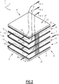
- the assembly 5 comprises for example four stages 15, 17, 19, 21 superimposed in a direction Z, for example vertical, and two end plates 23, 25 respectively forming an upper face 27 and a lower face 29 of the assembly.
- the assembly 5 is for example of generally parallelepipedal shape.
- the assembly 5 comprises two side faces 31, 33 ( picture 2 ) opposite in a direction Y substantially perpendicular to the direction Z, and two side faces 35, 37 opposite in a direction X substantially perpendicular to the direction Z and to the direction Y.
- the side faces 31, 33, 35, 37 are for example rectangular, and two of them consecutive around the direction Z advantageously form a substantially right angle.
- the side face 31 comprises for example three inlets E1, E2, E3 for three flows F11, F12 and F13 from the cold fluid F1, and two outlets S1', S2' for two flows F21' and F22' intended to form the cooled fluid F2'.
- the side face 33 has two entrances (not visible on the figure 2 because located at the rear) for two flows F21 and F22 from the hot fluid F2, and three outlets (also not visible on the figure 2 ) for three streams F11', F12' and F13' intended to form the heated fluid F1'.
- the stages 15, 17, 19, 21 are substantially similar to each other.
- inlets and outlets are presented for example as slots extending along the direction X on the side faces 31, 33.
- the inputs E1, E2 and E3 are for example aligned along the direction Z and located opposite the member 7.
- the outputs S1 'and S2' are for example superimposed in the direction Z and located vis-à-vis the member 13. The same applies to the outputs located on the side face 33, except that 'they are located opposite the organ 9.
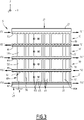
- Stages 15 to 21 are formed by plates 39, 41, 43, 45, 47 ( picture 3 ) substantially perpendicular to the Z direction and alternating with parts 49, 51, 53, 55.
- parts 49, 51, 53, 55 are similar to each other, so only part 53 belonging to the floor 19 will be described below with reference to the figures 3 to 5 .
- Part 53 comprises at least 90% by weight of a metal or a metal alloy.
- Advantageously part 53 is made of stainless steel, for example 316L.
- part 53 is made of copper, aluminum or titanium.
- the part 53 is formed by a metal sheet 58 folded on itself accordion-like, in the example parallel to the direction X.
- the part 53 defines a plurality of circulation channels 63 located above the metal sheet 58 and intended to receive the flow F12, and a plurality of circulation channels 65 located under the metal sheet and intended to receive the flow F22.
- Part 53 is fixed to plates 43, 45, advantageously by brazing.
- part 53 is bonded to the rest of assembly 5, in particular if the latter is not entirely metallic.
- Part 53 has two opposite faces 59, 60 along direction X, on which a corrugated edge 60A of sheet 58 defines interstices 61.
- the faces 59, 60 are for example perpendicular to the direction X.
- the circulation channels 63, 65 are oriented substantially along the X direction.
- the interstices 61 have two edges 67, 69 ( picture 3 ) opposite in the direction Y and separated by a maximum distance D less than or equal to 550 ⁇ m, preferably less than or equal to 250 ⁇ m, and for example less than 150 ⁇ m.
- Plates 39, 41, 43, 45, 47 are structurally analogous to each other.
- the plates 39, 43, 47 have the same orientation in space, while the plates 41 and 45 have another orientation in space, deduced from the first for example by a rotation of 180° around the direction X .
- Each of the plates 39, 41, 43, 45, 47 has for example a generally rectangular shape in view along the direction Z.
- Each of the plates comprises two cutouts 71, 73 ( figure 5 ) for example symmetrical to each other with respect to a point S located at the center of the plate.
- Each of the cutouts 71, 73 extends in the example along the Y direction from one of the side faces 31 or 33 of the assembly 5, above or below the circulation channels 63, 65.
- the plates 39, 41, 43, 45, 47 are made of metal or a metal alloy, for example stainless steel, advantageously 316L.
- the plates are fixed respectively on the parts 49, 51, 53, 55, for example by conventional brazing.
- the plates are made of copper, aluminum, or titanium.
- the plates are made of the same material as parts 49, 51, 53, 55.
- the bodies 7, 9, 11, 13 are advantageously similar to each other. Also, only the member 7 will be described in detail below.
- the member 7 is made of metal or a metal alloy, for example stainless steel, advantageously 316L.
- member 7 is made of copper, aluminum or titanium.
- member 7 is made of the same material as plates 39, 41, 43, 45, 47.
- the member 7 comprises a tubular upper part 79, and a lower part 81 situated in the extension of the first part in the direction Z and obtained by cutting according to a plane corresponding to the upper face 27 and according to a plane corresponding to the lateral face 31.
- the member 7 further comprises a bottom 83.
- the heat exchanger 1 also comprises metal layers 85 electro-deposited in particular on the faces 59 and 60 of the parts 49, 51, 53, 55, and possibly on other faces.
- the layers 85 are adapted to block the interstices 61 on the faces 59, 60.
- the layers 85 are for example made of nickel.
- the layers 85 are made of copper, copper-nickel alloy, or aluminum.
- the thickness of layer 85 is advantageously between 0.5 mm and 5 mm, and is for example around 1 mm.
- the heat exchanger 1 comprises other electro-deposited layers (not shown).
- assembly 5 or heat exchanger 1 are covered by one or more electrodeposited layers.
- a heat pipe according to the invention is also described. This is not strictly represented in the figures, but is easily deduced therefrom.
- the plates 43, 45 are replaced by plates without cutting.
- the circulation channels 63, 65 respectively define an upper space located above the part 53, and a lower space located below the part 53. These spaces are closed in the X direction by the electro-deposited layers 85, and along the Y direction by the extreme folds of the part 53. Suitable fluids, distinct or not, are present in these spaces and free to circulate in the circulation channels 63, 65.
- the heat pipe contains a fluid injected by a hermetic filling device (not shown), for example a tapping made on the plate 43.
- the heat pipe is used in a vertical position, i.e. the X direction is then vertical.
- face 60 is in the high position and face 59 in the low position.
- the lower face 59 is placed on an object (not shown) to be cooled, for example an electronic component whose temperature must be maintained between 20 and 30°C.
- the heat thus collected at the face 59 causes the boiling of the fluid, in the liquid phase in the lower part of the heat pipe.
- the steam propagates up to the upper part, towards the face 58, which itself is cooled on its external part by a cooling/refrigerating device. Consequently, on this upper face 60, the vapor condenses and falls by gravity towards the lower part. State changes by successive evaporations and condensations make it possible to extract a very large quantity of heat from the object in contact with the face 59 in the lower part.
- the heat pipe is particularly efficient, because both in the lower zone (evaporation) and in the upper zone (condensation), the exchange surface/volume ratio is very high.
- the manufacture of the heat exchanger 1 will now be described. It illustrates a method of manufacture according to the invention.
- the parts 49, 51, 53, 55 are provided, as well as the plates 39, 41, 43, 45, 47 spacers, the end plates 23, 25, and the organs 7, 9, 11, 13.
- Brazing sheets 87 are made of brazing alloy, for example BNi-2 alloy, or any other material suitable for the composition of parts 49, 51, 53, 55 and plates 39, 41, 43, 45, for example in eutectic copper-silver alloy for brazing copper parts.
- brazing alloy for example BNi-2 alloy, or any other material suitable for the composition of parts 49, 51, 53, 55 and plates 39, 41, 43, 45, for example in eutectic copper-silver alloy for brazing copper parts.
- the assembly of the parts 49, 51, 53, 55, of the plates 39, 41, 43, 45, 47, of the end plates 23 and 25, and of the brazing sheets 87 is carried out by stacking, and held mechanically using tools suitable (not shown).
- assembly is heated to a brazing temperature to obtain assembly 5.
- the assembly is not obtained by brazing, but for example by bonding.
- the assembly 5 then undergoes chemical degreasing and electrolytic degreasing. These operations are known per se to those skilled in the art in order to clean surfaces with a view to carrying out deposits by electrolysis.
- the electrolytic degreasing is for example carried out in a conventional bath for stainless steel and nickel in cathodic polarization, with a current density of 4A/dm 2 for 10 minutes at 35°C.
- the assembly 5 then undergoes anodic activation in an acid medium, for example for two minutes.
- the assembly 5 thus cleaned and activated undergoes electrolytic pre-nickel plating by immersion in a Wood bath, for example at 25° C., with a cathodic current density of 6 A/dm 2 for 8 minutes.
- Wood's bath comprises, for example, nickel chloride NiCl 2 .6H 2 O at 100-250 g/liter, and hydrochloric acid HCl at 85-125 cm 3 /liter.
- the assembly 5 thus prepared is immersed in an electrolytic bath 89, and the layer 85 is electro-deposited on the faces 59, 60 of the parts 49, 51, 53, 55.
- the electrolytic bath 89 advantageously comprises nickel sulfamate.
- the electrolytic bath 89 is for example a mixture of copper sulphate and sulfuric acid.
- the electrolytic bath 89 comprises for example an organic solvent, such as a mixture of tetrahydrofuran and benzene, in which is advantageously dissolved aluminum chloride AlCl 3 and lithium aluminum hydride LiAlH 4 .
- assembly 5 is electrically connected to the cathode of a generator 91. Assembly 5 therefore plays the role of cathode in the electrolysis.
- a consumable anode 93 is immersed in the electrolytic bath 89 and connected to the anode of the generator 91.
- the anode 93 is for example made up of sulfur-depolarized nickel balls.
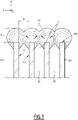
- metallic seeds 95 appear almost exclusively at the level of the interstices 61 on the corrugated edge 60A of the parts 49, 51, 53, 55.
- the seeds 95 grow by forming a blister of the corrugated edge.
- the seeds 95 meet in the Y direction and grow further to form the layer 85, which completely blocks the interstices 61 of the faces 59, 60.
- the seeds 85 grow little in the direction X towards the inside of the circulation channels 63, 65.
- the members 7, 9, 11, 13 are then fixed to the assembly 5 by brazing, welding, gluing or any other process suitable for the heat exchanger 1.
- the members 7, 9, 11, 13 are fixed to the assembly 5 during the assembly operation, before the electroplating step or steps.
- the heat pipe described above is made in a similar way. It is for example composed of five parts: the sheet 58, the two distribution plates 43 and 45 provided with opening 71 closed on their outer edge and two end plates 23 and 25. Initially, the parts 23, 25 , 43, 45 and 53 are assembled by brazing, analogously to the case of the exchanger. Secondly, faces 59 and 60 are sealed by electrodeposition. Thirdly, the end plates 23 and 25 are drilled to allow the attachment by welding or brazing of tubes used to fill the fluid. This last operation can also take place before the deposition step.
- the cold fluid F1 ( figure 1 ) enters the member 7.
- the cold fluid F1 flows along the side face 31 of the assembly 5 and is divided into the flows F11, F12 and F13 ( picture 2 ).
- Flows F11, F12 and F13 enter set 5 through inputs E1, E2, E3.
- the flow F12 flows substantially along the Y direction in the cutout 73 of the plate 43 which acts as a distributor ( figure 5 ). Flowing F12 then enters circulation channels 63 (upper) in room 53 and circulation channels 65 (lower) in room 51 ( picture 3 ). As it flows in the direction X in the circulation channels 63, 65, the cold fluid exchanges heat with the hot fluid F2 located respectively on the other side of each of the parts 51, 53, and cools and becomes flux F12'. Flow F12' leaves assembly 5 via face 33 at the level of cutout 71 of plate 43.
- flows F11 and F13 flow through assembly 5 from side face 31 to side face 33 by exchanging heat in countercurrent with flows F21 and F22.
- the hot fluid F2 enters the member 11 and is divided into the flows F21 and F22 which enter the assembly 5 through the side face 33.
- the flow F22 enters through the cutout 73 of the plate 45 and enters the channels 65 (lower) defined by the part 53 and the channels 63 of the part 55.
- the flows F21 and F22 are cooled by heat exchange through the parts 49, 51 on the one hand and 53, 55 on the other hand and come out in the form of cooled flows F21' and F22'.
- Streams F21' and F22' combine in member 13 to form cooled fluid F2'.
- the method allows the manufacture of the heat exchanger 1 or of the heat pipe described above, by treating the parts 49, 51, 53, 55 having the micro-interstices 61. This allows in particular to give small dimensions to the heat exchanger 1 and to the heat pipe described above.
- the method allows the manufacture of the heat exchanger 1 or of the heat pipe by minimizing the number of brazing steps. This makes it possible to obtain exchangers of small dimensions, at reduced cost, and possibly in a single brazing step.
Landscapes
- Chemical & Material Sciences (AREA)
- Engineering & Computer Science (AREA)
- Organic Chemistry (AREA)
- Metallurgy (AREA)
- Materials Engineering (AREA)
- Electrochemistry (AREA)
- Chemical Kinetics & Catalysis (AREA)
- Mechanical Engineering (AREA)
- General Engineering & Computer Science (AREA)
- Physics & Mathematics (AREA)
- Thermal Sciences (AREA)
- Sustainable Development (AREA)
- Life Sciences & Earth Sciences (AREA)
- Heat-Exchange Devices With Radiators And Conduit Assemblies (AREA)
- Electroplating Methods And Accessories (AREA)
Description
- La présente invention concerne un procédé de fabrication d'un échangeur ou d'un caloduc comprenant un ensemble comprenant au moins une pièce comportant au moins 90% en masse d'un métal ou un alliage de métaux, la pièce définissant une pluralité de canaux de circulation pour un ou plusieurs fluides.
- L'invention concerne aussi un échangeur ou un caloduc correspondant.
- Il est bien connu recourir au brasage pour assembler des pièces, en particulier en vue d'assembler un échangeur thermique ou un caloduc.
- En outre, un type connu d'échangeur thermique met en œuvre une pièce constituée d'une feuille métallique repliée sur elle-même en accordéon. Deux plaques fixées de part et d'autre de la feuille métallique définissent des canaux de circulation parallèles entre eux et situés de chaque côté de la feuille métallique. Les extrémités longitudinales des canaux débouchent sur des faces de la feuille en accordéon dans lesquelles les canaux définissent des interstices.
- Dans le cas d'un échangeur thermique, les canaux situés d'un côté de la feuille métallique sont parcourus par un fluide froid, tandis que ceux situés de l'autre côté sont parcourus par un fluide chaud. Ainsi, entre deux plaques circulent deux fluides, séparés l'un de l'autre par la feuille métallique et échangeant de la chaleur l'un avec l'autre au travers de la feuille métallique.
- Les feuilles en accordéon, et les plaques recouvertes sur leurs deux faces d'un film de brasure sont alternativement empilées les unes sur les autres de façon à constituer un bloc appelé « matrice » ou « ensemble ». Cet empilement est ensuite assemblé en une première étape dans un four de brasage. L'ensemble comprend généralement une première et dernière plaque d'une épaisseur plus importante que les plaques.
- Pour étanchéifier l'ensemble sur son pourtour, des barres, appelées "barres de fermeture" sont généralement fixées sur la matrice. Des têtes d'alimentation en fluides sont ensuite ajoutées à la matrice pour constituer l'échangeur.
- Du fait des différentiels de dilatation entre les pièces, qui empêchent de trop contraindre géométriquement les constituants du futur échangeur, il est généralement pratiqué plusieurs étapes de brasage, entre lesquelles des opérations d'usinage sont réalisées de façon à garantir les jeux entre pièces. Cette pratique nécessite une grande maîtrise des nuances d'alliages d'apport de façon à ne pas dégrader lors de l'étape suivante les jonctions réalisées à l'étape précédente.
- Une première méthode consiste à réaliser, dans un premier temps, un cadre fermé ou semi-ouvert dans lequel on va insérer une feuille en accordéon pour l'assembler par brasage une première fois. Dans un deuxième temps, on assemble par brasage un ensemble de ces cadres afin de constituer la matrice de l'échangeur. Dans un troisième temps, les tubes de connexion des fluides sont brasés sur la matrice.
- Une seconde méthode consiste, dans un premier temps, à assembler par brasage l'ensemble des feuilles en accordéon sur l'ensemble des plaques, auxquelles sont jointes éventuellement les barres de fermeture orientées longitudinalement. Dans un deuxième temps, on usine les faces des feuilles en accordéon pour les aligner parfaitement, afin de les assembler par brasage avec les barres de fermetures orientées transversalement. On obtient ainsi la matrice de l'échangeur. Enfin, dans un troisième temps, les tubes de connexion des fluides sont soudés ou brasés sur la matrice.
- Par ailleurs, il existe un besoin, dans différents secteurs industriels, tels que l'automobile ou l'aéronautique, de réduire, d'une part, l'encombrement créé par les circuits thermiques et leur masse et, d'autre part, la quantité de fluides impliqués dans les échanges. En effet, ces fluides ont parfois une incidence sur l'environnement, qu'il convient de réduire au maximum.
- Les mêmes remarques valent pour des caloducs intégrant de telles feuilles en accordéon ou plus généralement des pièces métalliques comportant des micro-interstices.
- Le document
KR 101 891 444 B1 - Toutefois, plus les échangeurs sont de dimensions réduites, plus la deuxième étape s'avère difficile, c'est-à-dire le brasage des barres de fermeture sur la face des feuilles en accordéon présentant les interstices décrits plus haut.
- Un but de l'invention est donc de fournir un procédé de fabrication d'un échangeur thermique ou d'un caloduc intégrant une pièce telle que la pièce en accordéon précitée, c'est-à-dire présentant des micro-interstices, en particulier lorsque l'échangeur ou le caloduc est de faibles dimensions.
- A cet effet, l'invention concerne un procédé de fabrication d'un échangeur thermique ou d'un caloduc selon la revendication 1.
- Selon des modes particuliers de réalisation, le procédé comprend l'une ou plusieurs des caractéristiques correspondant aux revendications 2 à 9, prise(s) isolément ou selon toutes les combinaisons techniquement possibles.
- L'invention concerne aussi un échangeur thermique ou un caloduc selon la revendication 10.
- Selon des modes particuliers de réalisation, l'échangeur ou le caloduc sont susceptibles d'être obtenus, ou sont effectivement obtenus, par un procédé de fabrication tel que décrit ci-dessus.
- L'invention sera mieux comprise à la lecture de la description qui va suivre, donnée uniquement à titre d'exemple et faite en se référant aux dessins annexés, sur lesquels :
- la
figure 1 est une vue en perspective d'un échangeur thermique selon l'invention, - la
figure 2 est une vue en perspective d'un ensemble (matrice) de l'échangeur thermique représenté sur lafigure 1 , les collecteurs de fluide ayant été supprimés, - la
figure 3 est une vue de face, partielle, de l'ensemble représenté sur lesfigures 1 et2 , - la
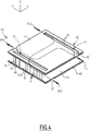
figure 4 est une vue en perspective d'un des étages de l'ensemble représenté sur lesfigures 2 et3 , - la
figure 5 est une vue en perspective éclatée de l'étage représenté sur lafigure 4 , et de couches électro-déposées, - la
figure 6 est une vue schématique illustrant une étape d'immersion de l'ensemble dans un bain électrolytique d'un procédé selon l'invention, et - la
figure 7 est une vue schématique, en section, illustrant une étape d'électrodéposition d'un procédé selon l'invention. - En référence aux
figures 1 à 3 , on décrit un échangeur thermique 1 selon l'invention. - Comme visible sur la
figure 1 , l'échangeur thermique 1 comprend un ensemble 5 (matrice), et quatre organes 7, 9, 11, 13 pour respectivement apporter un fluide froid F1, récupérer un fluide réchauffé F1', amener un fluide chaud F2, et récupérer un fluide refroidi F2'. - Le fluide froid est par exemple de l'eau ou un mélange d'eau et de glycol.
- Le fluide chaud est par exemple un liquide frigorigène de type HFE (hydrofluoroéther) ou HFO (hydrofluorooléfine), comme c'est le cas dans une pompe à chaleur. Dans le cas du refroidissement de l'huile d'un moteur thermique, le fluide chaud est l'huile à refroidir.
- Comme visible sur les
figures 2 et3 , l'ensemble 5 comprend par exemple quatre étages 15, 17, 19, 21 superposés selon une direction Z par exemple verticale, et deux plaques extrêmes 23, 25 formant respectivement une face supérieure 27 et une face inférieure 29 de l'ensemble. - L'ensemble 5 est par exemple de forme générale parallélépipédique. L'ensemble 5 comporte deux faces latérales 31, 33 (
figure 2 ) opposées selon une direction Y sensiblement perpendiculaire à la direction Z, et deux faces latérales 35, 37 opposées selon une direction X sensiblement perpendiculaire à la direction Z et à la direction Y. - Les faces latérales 31, 33, 35, 37 sont par exemple rectangulaires, et deux d'entre elles consécutives autour de la direction Z forment avantageusement un angle sensiblement droit.
- La face latérale 31 comporte par exemple trois entrées E1, E2, E3 pour trois flux F11, F12 et F13 issus du fluide froid F1, et deux sorties S1', S2' pour deux flux F21' et F22' destinés à former le fluide refroidi F2'.
- La face latérale 33 comporte deux entrées (non visibles sur la
figure 2 car situées à l'arrière) pour deux flux F21 et F22 issus du fluide chaud F2, et trois sorties (également non visibles sur lafigure 2 ) pour trois flux F11', F12' et F13' destinés à former le fluide réchauffé F1'. - Comme visible sur les
figures 2 et3 , les étages 15, 17, 19, 21 sont sensiblement analogues les uns aux autres. - Les entrées et les sorties précitées se présentent par exemple comme des fentes s'étendant selon la direction X sur les faces latérales 31, 33.
- Les entrées E1, E2 et E3 sont par exemple alignées selon la direction Z et situées en vis-à-vis de l'organe 7.
- Il en va de même pour les entrées situées sur la face latérale 33, si ce n'est qu'elles sont situées en vis-à-vis de l'organe 11.
- Les sorties S1' et S2' sont par exemple superposées selon la direction Z et situées en vis-à-vis de l'organe 13. Il en va de même pour les sorties situées sur la face latérale 33, si ce n'est qu'elles sont situées en vis-à-vis de l'organe 9.
- Les étages 15 à 21 sont formés par des plaques 39, 41, 43, 45, 47 (
figure 3 ) sensiblement perpendiculaires à la direction Z et alternant avec des pièces 49, 51, 53, 55. Dans l'exemple représenté, les pièces 49, 51, 53, 55 sont analogues entre elles, aussi seule la pièce 53 appartenant à l'étage 19 sera décrite ci-après en référence auxfigures 3 à 5 . - La pièce 53 comprend au moins 90% en masse d'un métal ou d'un alliage métallique. Avantageusement la pièce 53 est en acier inoxydable, par exemple en 316L.
- Selon des variantes, la pièce 53 est en cuivre, en aluminium, ou en titane.
- La pièce 53 est formée par une feuille métallique 58 repliée sur elle-même en accordéon, dans l'exemple parallèlement à la direction X. La pièce 53 définit une pluralité de canaux de circulation 63 situés au-dessus de la feuille métallique 58 et destinés à recevoir le flux F12, et une pluralité de canaux de circulation 65 situés sous la feuille métallique et destinés à recevoir le flux F22.
- La pièce 53 est fixée sur les plaques 43, 45, avantageusement par brasage.
- Selon un mode de réalisation particulier, la pièce 53 est collée sur le reste de l'ensemble 5, notamment si celui-ci n'est pas intégralement métallique.
- La pièce 53 comporte deux faces 59, 60 opposées selon la direction X, sur lesquelles un bord ondulé 60A de la feuille 58 définit des interstices 61.
- Les faces 59, 60 sont par exemple perpendiculaires à la direction X.
- Les canaux de circulation 63, 65 sont orientés sensiblement selon la direction X.
- Les interstices 61 comportent deux bords 67, 69 (
figure 3 ) opposés selon la direction Y et séparés par une distance maximale D inférieure ou égale à 550 µm, de préférence inférieure ou égale à 250 µm, et par exemple inférieure à 150 µm. - Les plaques 39, 41, 43, 45, 47 sont structurellement analogues les unes aux autres. Les plaques 39, 43, 47 présentent la même orientation dans l'espace, tandis que les plaques 41 et 45 présentent une autre orientation dans l'espace, se déduisant de la première par exemple par une rotation de 180° autour de la direction X.
- Chacune des plaques 39, 41, 43, 45, 47 présente par exemple une forme générale rectangulaire en vue selon la direction Z. Chacune des plaques comprend deux découpes 71, 73 (
figure 5 ) par exemple symétriques l'une de l'autre par rapport à un point S situé au centre de la plaque. - Chacune des découpes 71, 73 s'étend dans l'exemple selon la direction Y à partir d'une des faces latérales 31 ou 33 l'ensemble 5, au-dessus ou en-dessous des canaux de circulation 63, 65.
- Les plaques 39, 41, 43, 45, 47 sont en métal ou en alliage métallique, par exemple en acier inoxydable, avantageusement en 316L. Les plaques sont fixées respectivement sur les pièces 49, 51, 53, 55, par exemple par un brasage classique.
- En variante, les plaques sont en cuivre, en aluminium, ou en titane.
- Avantageusement, les plaques sont réalisées dans le même matériau que les pièces 49, 51, 53, 55.
- Les organes 7, 9, 11, 13 sont avantageusement analogues les uns aux autres. Aussi, seul l'organe 7 sera décrit en détail ci-après.
- L'organe 7 est en métal ou en alliage métallique, par exemple en acier inoxydable, avantageusement en 316L.
- En variante, l'organe 7 est en cuivre, en aluminium, ou en titane.
- Avantageusement, l'organe 7 est réalisé dans le même matériau que les plaques 39, 41, 43, 45, 47.
- L'organe 7 comprend une partie supérieure 79 tubulaire, et une partie inférieure 81 située dans le prolongement de la première partie selon la direction Z et obtenue par découpe selon un plan correspondant à la face supérieure 27 et selon un plan correspondant à la face latérale 31. L'organe 7 comprend en outre un fond 83.
- L'échangeur thermique 1 comprend aussi des couches 85 métalliques électro-déposées notamment sur les faces 59 et 60 des pièces 49, 51, 53, 55, et éventuellement sur d'autres faces.
- Les couches 85 sont adaptées pour boucher les interstices 61 sur les faces 59 ,60.
- Les couches 85 sont par exemple en nickel.
- Selon des variantes, les couches 85 sont en cuivre, alliage cuivre-nickel, ou en aluminium.
- L'épaisseur de la couche 85 est avantageusement comprise entre 0,5 mm et 5mm, et est par exemple d'environ 1 mm.
- Avantageusement, l'échangeur thermique 1 comporte d'autres couches électro-déposées (non représentées). Par exemple l'ensemble 5 ou l'échangeur thermique 1 sont recouverts par une ou plusieurs couches électro-déposées.
- On décrit aussi un caloduc selon l'invention. Celui-ci n'est pas strictement représenté sur les figures, mais s'en déduit facilement. Par exemple, sur la
figure 5 , on remplace les plaques 43, 45 par des plaques sans découpe. Les canaux de circulation 63, 65 définissent respectivement un espace supérieur situé au-dessus de la pièce 53, et un espace inférieur situé en dessous de la pièce 53. Ces espaces sont fermés selon la direction X par les couches 85 électro-déposées, et selon la direction Y par les plis extrêmes de la pièce 53. Des fluides adaptés, distincts ou non, sont présent dans ces espaces et libres de circuler dans les canaux de circulation 63, 65. - Le caloduc contient un fluide injecté par un dispositif de remplissage hermétique (non représenté), par exemple un piquage réalisé sur la plaque 43.
- Le caloduc est utilisé en position verticale, c'est-à-dire que la direction X est alors verticale. Par exemple, la face 60 est en position haute et la face 59 en position basse.
- La face basse 59 est posée sur un objet (non représenté) à refroidir, par exemple un composant électronique dont la température doit être maintenue entre 20 et 30°C.
- La chaleur ainsi récoltée au niveau de la face 59 provoque l'ébullition du fluide, en phase liquide dans la partie basse du caloduc. La vapeur se propage jusqu'en partie haute, en direction de la face 58, qui elle-même est refroidie sur sa partie externe par un dispositif réfrigérant/frigorigène. En conséquence, sur cette face 60supérieure, la vapeur condense et retombe par gravité vers la partie basse. Les changements d'état par évaporations et condensations successives permettent d'extraire une très grande quantité de chaleur de l'objet en contact avec la face 59 dans la partie basse.
- Le caloduc est particulièrement efficace, car aussi bien dans la zone basse (évaporation) que dans la zone haute (condensation), le ratio surface d'échange/volume est très important.
- La fabrication de l'échangeur thermique 1 va maintenant être décrite. Elle illustre un procédé de fabrication selon l'invention.
- On fournit tout d'abord les pièces 49, 51, 53, 55, ainsi que les plaques 39, 41, 43, 45, 47 intercalaires, les plaques extrêmes 23, 25, et les organes 7, 9, 11, 13.
- Ces éléments sont empilés comme représenté sur les
figures 3 et4 selon la direction Z, en intercalant entre chacun des feuilles de brasage 87 comme représenté sur lafigure 5 . - Les feuilles de brasage 87 sont en alliage de brasure, par exemple en alliage BNi-2, ou dans tout autre matériau adapté à la composition des pièces 49, 51, 53, 55 et des plaques 39, 41, 43, 45, par exemple en alliage eutectique cuivre-argent pour braser des pièces en cuivre.
- L'assemblage des pièces 49, 51, 53, 55, des plaques 39, 41, 43, 45, 47, des plaques extrêmes 23 et 25, et des feuilles de brasage 87 est réalisé par empilement, et maintenu mécaniquement grâce à un outillage adapté (non représenté).
- Puis, on chauffe l'assemblage à une température de brasage pour obtenir l'ensemble 5.
- En variante, l'assemblage n'est pas obtenu par brasage, mais par exemple par collage.
- Avantageusement, l'ensemble 5 subit ensuite un dégraissage chimique et un dégraissage électrolytique. Ces opérations sont connues en elles-mêmes de l'homme du métier afin de nettoyer des surfaces en vue de réaliser des dépôts par électrolyse.
- Le dégraissage électrolytique est par exemple réalisé dans un bain classique pour acier inoxydable et nickel en polarisation cathodique, avec une densité de courant de 4A/dm2 pendant 10 minutes à 35°C.
- Avantageusement, l'ensemble 5 subit ensuite une activation anodique en milieu acide, par exemple pendant deux minutes.
- Optionnellement, l'ensemble 5 ainsi nettoyé et activé subit un pré-nickelage électrolytique par immersion dans un bain de Wood, par exemple à 25°C, avec une densité de courant cathodique de 6A/dm2 pendant 8 minutes.
- Le bain de Wood comprend, par exemple, du chlorure de nickel NiCl2.6H2O à 100-250 g/litre, et de l'acide chlorhydrique HCl à 85-125 cm3/litre.
- Ensuite, comme représenté schématiquement sur la
figure 6 , l'ensemble 5 ainsi préparé est immergé dans un bain électrolytique 89, et la couche 85 est électro-déposée sur les faces 59, 60 des pièces 49, 51, 53, 55. - Le bain électrolytique 89 comprend avantageusement du sulfamate de nickel.
- En variante, si les pièces 49, 51, 53, 55 sont en cuivre, le bain électrolytique 89 est par exemple un mélange de sulfate de cuivre et d'acide sulfurique.
- En variante, si les pièces 49, 51, 53, 55 sont en aluminium, le bain électrolytique 89 comporte par exemple un solvant organique, tel qu'un mélange de tétrahydrofurane et de benzène, dans lequel est avantageusement dissous du chlorure d'aluminium AlCl3 et de l'hydrure d'aluminium lithium LiAlH4.
- Pendant l'électrodéposition de la couche 85, l'ensemble 5 est relié électriquement à la cathode d'un générateur 91. L'ensemble 5 joue donc le rôle de cathode dans l'électrolyse.
- Une anode 93 consommable est immergée dans le bain électrolytique 89 et reliée à l'anode du générateur 91. L'anode 93 est par exemple constituée de billes de nickel dépolarisées au soufre.
- De manière surprenante, comme visible sur la
figure 7 , des germes 95 métalliques apparaissent presque uniquement au niveau des interstice 61 sur le bord ondulé 60A des pièces 49, 51, 53, 55. Les germes 95 grandissent en formant une boursoufflure du bord ondulé. Puis, les germes 95 se rejoignent dans la direction Y et croissent encore pour former la couche 85, laquelle bouche totalement les interstices 61 des faces 59, 60. - De manière surprenante également, les germes 85 croissent peu dans la direction X vers l'intérieur des canaux de circulation 63, 65.
- Ainsi, les interstices 61 des faces 59, 60 sont obturés de manière simple et avantageuse.
- Les organes 7, 9, 11, 13 sont ensuite fixés sur l'ensemble 5 par brasage, soudure, collage ou tout autre procédé adapté à l'échangeur thermique 1.
- Selon une variante, les organes 7, 9, 11, 13 sont fixés sur l'ensemble 5 pendant l'opération d'assemblage, avant la ou les étapes d'électrodéposition.
- Optionnellement, d'autres étapes d'électrodéposition sont réalisées pour parachever l'échangeur thermique 1.
- Le caloduc décrit plus haut est fabriqué de manière analogue. Il est par exemple composé de cinq pièces : la feuille 58, les deux plaques de distribution 43 et 45 dotées d'ouverture 71 fermées sur leur bord extérieur et de deux plaques extrêmes 23 et 25. Dans un premier temps, les pièces 23, 25, 43, 45 et 53 sont assemblées par brasage, de manière analogue au cas de l'échangeur. Dans un deuxième temps, les faces 59 et 60 sont obturées par électrodéposition. Dans un troisième temps, les plaques extrêmes 23 et 25 sont percées pour permettre la fixation par soudage ou brasage de tubes servant au remplissage du fluide. Cette dernière opération peut aussi avoir lieu avant l'étape de dépôt.
- Le fonctionnement de l'échangeur thermique 1 se déduit de sa structure et va maintenant être brièvement décrit.
- Le fluide froid F1 (
figure 1 ) pénètre dans l'organe 7. Le fluide froid F1 s'écoule le long de la face latérale 31 de l'ensemble 5 et se divise en les flux F11, F12 et F13 (figure 2 ). - Les flux F11, F12 et F13 entrent dans l'ensemble 5 par les entrées E1, E2, E3.
- Le flux F12 s'écoule sensiblement selon la direction Y dans la découpe 73 de la plaque 43 qui joue le rôle de distributeur (
figure 5 ). Le flux F12 s'écoule pénètre alors dans les canaux de circulation 63 (supérieurs) de la pièce 53 et dans les canaux de circulation 65 (inférieurs) de la pièce 51 (figure 3 ). A mesure qu'il s'écoule dans la direction X dans les canaux de circulation 63, 65, le fluide froid échange de la chaleur avec le fluide chaud F2 situé respectivement de l'autre côté de chacune des pièces 51, 53, et se refroidit et devient le flux F12'. Le flux F12' sort de l'ensemble 5 par la face 33 au niveau de la découpe 71 de la plaque 43. - De même, les flux F11 et F13 s'écoulent au travers de l'ensemble 5 depuis la face latérale 31 jusqu'à la face latérale 33 en échangeant de la chaleur à contre-courant avec les flux F21 et F22.
- Une fois réchauffés, les flux F11, F12, F13 deviennent des flux réchauffés F11', F12' et F13' qui débouchent dans l'organe 9 et se combinent pour former le fluide réchauffé F1'.
- De même, le fluide chaud F2 pénètre dans l'organe 11 et se divise en les flux F21 et F22 qui entrent dans l'ensemble 5 par la face latérale 33.
- Par exemple, comme visible sur la
figure 4 , le flux F22 pénètre par la découpe 73 de la plaque 45 et entre dans les canaux 65 (inférieurs) définis par la pièce 53 et dans les canaux 63 de la pièce 55. Les flux F21 et F22 se refroidissent par échange thermique à travers les pièces 49, 51 d'une part et 53, 55 d'autre part et ressortent sous la forme de flux refroidis F21' et F22'. Les flux F21' et F22' se combinent dans l'organe 13 pour former le fluide refroidi F2'. - Ainsi, grâce aux caractéristiques décrites ci-dessus, le procédé permet la fabrication de l'échangeur thermique 1 ou du caloduc décrit ci-dessus, en traitant les pièces 49, 51, 53, 55 présentant les micro-interstices 61. Ceci permet en particulier de donner de faibles dimensions à l'échangeur thermique 1 et au caloduc décrits ci-dessus.
- En outre, le procédé permet la fabrication de l'échangeur thermique 1 ou du caloduc en minimisant le nombre d'étapes de brasage. Ceci permet d'obtenir des échangeurs de faibles dimensions, à coût réduit, et possiblement en une seule étape de brasage.
Claims (10)
- Procédé de fabrication d'un échangeur thermique (1) ou d'un caloduc, comprenant au moins les étapes suivantes :- obtention d'un ensemble (5) comprenant au moins une pièce (53) comportant au moins 90% en masse d'un métal ou un alliage de métaux, la pièce (53) ayant au moins une face (59) définissant une pluralité d'interstices (61), chacun des interstices (61) comportant au moins deux bords opposés (67, 69) séparés sur la face (59) par une distance maximale (D) inférieure ou égale à 550 micromètres, la pièce (53) définissant une pluralité de canaux de circulation (63, 65) pour des fluides (F1, F2), chacun des canaux de circulation (63, 65) définissant l'un des interstices, et- immersion de l'ensemble (5) dans un bain électrolytique (89) et électrodéposition d'une couche (85) métallique sur ladite face (59), ladite couche (85) étant adaptée pour boucher les interstices (61).
- Procédé de fabrication selon la revendication 1, dans lequel la pièce (53) comprend une feuille (58) métallique pliée en accordéon, un bord ondulé (60A) de la feuille (58) formant les bords (67, 69) des interstices (61), les canaux de circulation (63, 65) s'étendant parallèlement à, et de part et d'autre de la feuille (58).
- Procédé de fabrication selon l'une quelconque des revendications 1 ou 2, dans lequel la pièce (53) est en acier inoxydable, en cuivre, en aluminium, ou en titane.
- Procédé de fabrication selon l'une quelconque des revendications 1 à 3, dans lequel l'étape d'obtention de l'ensemble (5) comprend une sous-étape de fixation de la pièce (53) sur au moins deux plaques (43, 45), la pièce (53) étant située entre les deux plaques (43, 45) selon une direction (Z).
- Procédé de fabrication selon la revendication 4, dans lequel la sous-étape de fixation comprend un brasage de la pièce (53) sur lesdites au moins deux plaques (43, 45).
- Procédé de fabrication selon l'une quelconque des revendications 1 à 5, dans lequel le procédé comprend en outre l'une ou plusieurs des étapes suivantes préalablement à l'étape d'immersion et d'électrodéposition :- dégraissage chimique de l'ensemble (5),- dégraissage électrolytique de l'ensemble (5), et/ou- activation anodique acide de l'ensemble (5).
- Procédé de fabrication selon l'une quelconque des revendications 1 à 6, dans lequel le bain électrolytique (89) comprend du nickel, la couche (85) comportant majoritairement du nickel.
- Procédé de fabrication selon la revendication 7, dans lequel le bain électrolytique (89) comprend du sulfamate de nickel.
- Procédé de fabrication selon l'une quelconque des revendications 1 à 8, comprenant en outre une étape d'immersion de l'ensemble (5) dans un bain de Wood pour réaliser un pré-nickelage de la pièce (53) préalablement à ladite étape d'immersion de l'ensemble (5) dans un bain électrolytique (89) et d'électrodéposition.
- Echangeur thermique (1) ou caloduc comprenant un ensemble (5) comprenant au moins une pièce (53) comportant au moins 90% en masse d'un métal ou un alliage de métaux, la pièce (53) ayant au moins une face (59) définissant une pluralité d'interstices (61),caractérisé en ce que chacun des interstices (61) comporte au moins deux bords opposés (67, 69) séparés sur la face (59) par une distance maximale (D) inférieure ou égale à 550 micromètres, la pièce (53) définissant une pluralité de canaux de circulation (63, 65) pour des fluides (F1, F2), chacun des canaux de circulation (63, 65) définissant l'un des interstices (61),l'ensemble (5) comprenant une couche (85) métallique électro-déposée sur ladite face (59) et bouchant les interstices (61).
Applications Claiming Priority (2)
| Application Number | Priority Date | Filing Date | Title |
|---|---|---|---|
| FR1871828A FR3088999B1 (fr) | 2018-11-26 | 2018-11-26 | Procédé de fabrication d’un échangeur thermique ou d’un caloduc |
| PCT/EP2019/082195 WO2020109155A1 (fr) | 2018-11-26 | 2019-11-22 | Procédé de fabrication d'un échangeur thermique ou d'un caloduc |
Publications (2)
| Publication Number | Publication Date |
|---|---|
| EP3887743A1 EP3887743A1 (fr) | 2021-10-06 |
| EP3887743B1 true EP3887743B1 (fr) | 2022-05-18 |
Family
ID=65861459
Family Applications (1)
| Application Number | Title | Priority Date | Filing Date |
|---|---|---|---|
| EP19805692.1A Not-in-force EP3887743B1 (fr) | 2018-11-26 | 2019-11-22 | Procédé de fabrication d'un échangeur thermique ou d'un caloduc |
Country Status (3)
| Country | Link |
|---|---|
| EP (1) | EP3887743B1 (fr) |
| FR (1) | FR3088999B1 (fr) |
| WO (1) | WO2020109155A1 (fr) |
Families Citing this family (1)
| Publication number | Priority date | Publication date | Assignee | Title |
|---|---|---|---|---|
| CN112522747B (zh) * | 2020-11-19 | 2022-01-07 | 瑞声科技(南京)有限公司 | 均温板上盖板的制备方法以及均温板 |
Family Cites Families (4)
| Publication number | Priority date | Publication date | Assignee | Title |
|---|---|---|---|---|
| US20050263273A1 (en) * | 2004-05-26 | 2005-12-01 | Crumly William R | Electroformed microchannel cooler and methods of making same |
| KR100992961B1 (ko) * | 2010-07-30 | 2010-11-08 | 주식회사 동화엔텍 | 플레이트형 열교환기 제조방법 |
| FR3026890B1 (fr) * | 2014-10-03 | 2017-12-22 | Commissariat Energie Atomique | Procede de controle de la fermeture de cavite par depot non conforme d'une couche |
| KR101891444B1 (ko) * | 2017-09-29 | 2018-08-23 | 주식회사프로스트 | 니켈 도금에 의해 내식성이 강한 번들타입의 판형 열교환모듈 및 이의 제조방법 |
-
2018
- 2018-11-26 FR FR1871828A patent/FR3088999B1/fr not_active Expired - Fee Related
-
2019
- 2019-11-22 EP EP19805692.1A patent/EP3887743B1/fr not_active Not-in-force
- 2019-11-22 WO PCT/EP2019/082195 patent/WO2020109155A1/fr not_active Ceased
Also Published As
| Publication number | Publication date |
|---|---|
| EP3887743A1 (fr) | 2021-10-06 |
| FR3088999A1 (fr) | 2020-05-29 |
| WO2020109155A1 (fr) | 2020-06-04 |
| FR3088999B1 (fr) | 2020-12-11 |
Similar Documents
| Publication | Publication Date | Title |
|---|---|---|
| US6959853B2 (en) | Fluxless brazing method and method for manufacturing layered material systems for fluxless brazing | |
| EP0611235B1 (fr) | Echangeur de chaleur pour composants électroniques et appareillages électrotechniques | |
| EP3113902B1 (fr) | Tôle de brasage à placages multiples | |
| EP2710162B1 (fr) | Ensemble plaqué en alliages d'aluminium pour tube d'echangeur thermique a placage interne protecteur et a perturbateur brase | |
| EP3630403B1 (fr) | Procédé de brasage ou rechargement d'une pièce à micro-interstices, et échangeur thermique obtenu par un tel procédé | |
| FR2892038A1 (fr) | Tole multicouche a brasage | |
| FR2681419A1 (fr) | Echangeur de chaleur a faisceau tubulaire comportant plusieurs circuits de fluides. | |
| FR2967765A1 (fr) | Composant brasable et echangeur de chaleur le comportant | |
| EP3887743A1 (fr) | Procédé de fabrication d'un échangeur thermique ou d'un caloduc | |
| FR2953919A1 (fr) | Echangeur de chaleur en aluminium brase | |
| WO2021156233A1 (fr) | Procédé de fabrication d'un échangeur thermique ou d'un caloduc | |
| EP3728978B1 (fr) | Echangeur de chaleur avec éléments intercalaires superposés | |
| WO2019170868A1 (fr) | Echangeur thermique, ainsi que procédé de fabrication d'un tel échangeur thermique | |
| WO2024121005A1 (fr) | Echangeur de chaleur à structure alvéolaire | |
| FR3095692A1 (fr) | Elément pour échangeur de chaleur ou caloduc, et procédé de fabrication | |
| FR3009985A1 (fr) | Depot de brasure par pulverisation cathodique ou par depot en phase chimique | |
| FR3100058A1 (fr) | Echangeur de chaleur notamment pour véhicule automobile et procédé de fabrication d’un tel échangeur de chaleur | |
| FR2598794A1 (fr) | Condenseur notamment du type condenseur a plaques | |
| FR3075341A1 (fr) | Echangeur de chaleur avec elements intercalaires a texturation de surface | |
| WO2017109349A1 (fr) | Échangeur thermique, notamment pour véhicule automobile | |
| BE611402A (fr) |
Legal Events
| Date | Code | Title | Description |
|---|---|---|---|
| STAA | Information on the status of an ep patent application or granted ep patent |
Free format text: STATUS: UNKNOWN |
|
| STAA | Information on the status of an ep patent application or granted ep patent |
Free format text: STATUS: THE INTERNATIONAL PUBLICATION HAS BEEN MADE |
|
| PUAI | Public reference made under article 153(3) epc to a published international application that has entered the european phase |
Free format text: ORIGINAL CODE: 0009012 |
|
| STAA | Information on the status of an ep patent application or granted ep patent |
Free format text: STATUS: REQUEST FOR EXAMINATION WAS MADE |
|
| 17P | Request for examination filed |
Effective date: 20210525 |
|
| AK | Designated contracting states |
Kind code of ref document: A1 Designated state(s): AL AT BE BG CH CY CZ DE DK EE ES FI FR GB GR HR HU IE IS IT LI LT LU LV MC MK MT NL NO PL PT RO RS SE SI SK SM TR |
|
| GRAP | Despatch of communication of intention to grant a patent |
Free format text: ORIGINAL CODE: EPIDOSNIGR1 |
|
| STAA | Information on the status of an ep patent application or granted ep patent |
Free format text: STATUS: GRANT OF PATENT IS INTENDED |
|
| DAV | Request for validation of the european patent (deleted) | ||
| DAX | Request for extension of the european patent (deleted) | ||
| INTG | Intention to grant announced |
Effective date: 20211022 |
|
| RIN1 | Information on inventor provided before grant (corrected) |
Inventor name: BILLAT, PIERRE |
|
| GRAJ | Information related to disapproval of communication of intention to grant by the applicant or resumption of examination proceedings by the epo deleted |
Free format text: ORIGINAL CODE: EPIDOSDIGR1 |
|
| STAA | Information on the status of an ep patent application or granted ep patent |
Free format text: STATUS: REQUEST FOR EXAMINATION WAS MADE |
|
| GRAP | Despatch of communication of intention to grant a patent |
Free format text: ORIGINAL CODE: EPIDOSNIGR1 |
|
| STAA | Information on the status of an ep patent application or granted ep patent |
Free format text: STATUS: GRANT OF PATENT IS INTENDED |
|
| INTC | Intention to grant announced (deleted) | ||
| INTG | Intention to grant announced |
Effective date: 20211222 |
|
| GRAS | Grant fee paid |
Free format text: ORIGINAL CODE: EPIDOSNIGR3 |
|
| GRAA | (expected) grant |
Free format text: ORIGINAL CODE: 0009210 |
|
| STAA | Information on the status of an ep patent application or granted ep patent |
Free format text: STATUS: THE PATENT HAS BEEN GRANTED |
|
| AK | Designated contracting states |
Kind code of ref document: B1 Designated state(s): AL AT BE BG CH CY CZ DE DK EE ES FI FR GB GR HR HU IE IS IT LI LT LU LV MC MK MT NL NO PL PT RO RS SE SI SK SM TR |
|
| REG | Reference to a national code |
Ref country code: GB Ref legal event code: FG4D Free format text: NOT ENGLISH |
|
| REG | Reference to a national code |
Ref country code: CH Ref legal event code: EP |
|
| REG | Reference to a national code |
Ref country code: IE Ref legal event code: FG4D Free format text: LANGUAGE OF EP DOCUMENT: FRENCH |
|
| REG | Reference to a national code |
Ref country code: DE Ref legal event code: R096 Ref document number: 602019015150 Country of ref document: DE |
|
| REG | Reference to a national code |
Ref country code: AT Ref legal event code: REF Ref document number: 1493383 Country of ref document: AT Kind code of ref document: T Effective date: 20220615 |
|
| REG | Reference to a national code |
Ref country code: LT Ref legal event code: MG9D |
|
| REG | Reference to a national code |
Ref country code: NL Ref legal event code: MP Effective date: 20220518 |
|
| REG | Reference to a national code |
Ref country code: AT Ref legal event code: MK05 Ref document number: 1493383 Country of ref document: AT Kind code of ref document: T Effective date: 20220518 |
|
| PG25 | Lapsed in a contracting state [announced via postgrant information from national office to epo] |
Ref country code: SE Free format text: LAPSE BECAUSE OF FAILURE TO SUBMIT A TRANSLATION OF THE DESCRIPTION OR TO PAY THE FEE WITHIN THE PRESCRIBED TIME-LIMIT Effective date: 20220518 Ref country code: PT Free format text: LAPSE BECAUSE OF FAILURE TO SUBMIT A TRANSLATION OF THE DESCRIPTION OR TO PAY THE FEE WITHIN THE PRESCRIBED TIME-LIMIT Effective date: 20220919 Ref country code: NO Free format text: LAPSE BECAUSE OF FAILURE TO SUBMIT A TRANSLATION OF THE DESCRIPTION OR TO PAY THE FEE WITHIN THE PRESCRIBED TIME-LIMIT Effective date: 20220818 Ref country code: NL Free format text: LAPSE BECAUSE OF FAILURE TO SUBMIT A TRANSLATION OF THE DESCRIPTION OR TO PAY THE FEE WITHIN THE PRESCRIBED TIME-LIMIT Effective date: 20220518 Ref country code: LT Free format text: LAPSE BECAUSE OF FAILURE TO SUBMIT A TRANSLATION OF THE DESCRIPTION OR TO PAY THE FEE WITHIN THE PRESCRIBED TIME-LIMIT Effective date: 20220518 Ref country code: HR Free format text: LAPSE BECAUSE OF FAILURE TO SUBMIT A TRANSLATION OF THE DESCRIPTION OR TO PAY THE FEE WITHIN THE PRESCRIBED TIME-LIMIT Effective date: 20220518 Ref country code: GR Free format text: LAPSE BECAUSE OF FAILURE TO SUBMIT A TRANSLATION OF THE DESCRIPTION OR TO PAY THE FEE WITHIN THE PRESCRIBED TIME-LIMIT Effective date: 20220819 Ref country code: FI Free format text: LAPSE BECAUSE OF FAILURE TO SUBMIT A TRANSLATION OF THE DESCRIPTION OR TO PAY THE FEE WITHIN THE PRESCRIBED TIME-LIMIT Effective date: 20220518 Ref country code: BG Free format text: LAPSE BECAUSE OF FAILURE TO SUBMIT A TRANSLATION OF THE DESCRIPTION OR TO PAY THE FEE WITHIN THE PRESCRIBED TIME-LIMIT Effective date: 20220818 Ref country code: AT Free format text: LAPSE BECAUSE OF FAILURE TO SUBMIT A TRANSLATION OF THE DESCRIPTION OR TO PAY THE FEE WITHIN THE PRESCRIBED TIME-LIMIT Effective date: 20220518 |
|
| PG25 | Lapsed in a contracting state [announced via postgrant information from national office to epo] |
Ref country code: RS Free format text: LAPSE BECAUSE OF FAILURE TO SUBMIT A TRANSLATION OF THE DESCRIPTION OR TO PAY THE FEE WITHIN THE PRESCRIBED TIME-LIMIT Effective date: 20220518 Ref country code: PL Free format text: LAPSE BECAUSE OF FAILURE TO SUBMIT A TRANSLATION OF THE DESCRIPTION OR TO PAY THE FEE WITHIN THE PRESCRIBED TIME-LIMIT Effective date: 20220518 Ref country code: LV Free format text: LAPSE BECAUSE OF FAILURE TO SUBMIT A TRANSLATION OF THE DESCRIPTION OR TO PAY THE FEE WITHIN THE PRESCRIBED TIME-LIMIT Effective date: 20220518 Ref country code: IS Free format text: LAPSE BECAUSE OF FAILURE TO SUBMIT A TRANSLATION OF THE DESCRIPTION OR TO PAY THE FEE WITHIN THE PRESCRIBED TIME-LIMIT Effective date: 20220918 |
|
| PGFP | Annual fee paid to national office [announced via postgrant information from national office to epo] |
Ref country code: FR Payment date: 20220928 Year of fee payment: 4 |
|
| PG25 | Lapsed in a contracting state [announced via postgrant information from national office to epo] |
Ref country code: SM Free format text: LAPSE BECAUSE OF FAILURE TO SUBMIT A TRANSLATION OF THE DESCRIPTION OR TO PAY THE FEE WITHIN THE PRESCRIBED TIME-LIMIT Effective date: 20220518 Ref country code: SK Free format text: LAPSE BECAUSE OF FAILURE TO SUBMIT A TRANSLATION OF THE DESCRIPTION OR TO PAY THE FEE WITHIN THE PRESCRIBED TIME-LIMIT Effective date: 20220518 Ref country code: RO Free format text: LAPSE BECAUSE OF FAILURE TO SUBMIT A TRANSLATION OF THE DESCRIPTION OR TO PAY THE FEE WITHIN THE PRESCRIBED TIME-LIMIT Effective date: 20220518 Ref country code: ES Free format text: LAPSE BECAUSE OF FAILURE TO SUBMIT A TRANSLATION OF THE DESCRIPTION OR TO PAY THE FEE WITHIN THE PRESCRIBED TIME-LIMIT Effective date: 20220518 Ref country code: EE Free format text: LAPSE BECAUSE OF FAILURE TO SUBMIT A TRANSLATION OF THE DESCRIPTION OR TO PAY THE FEE WITHIN THE PRESCRIBED TIME-LIMIT Effective date: 20220518 Ref country code: DK Free format text: LAPSE BECAUSE OF FAILURE TO SUBMIT A TRANSLATION OF THE DESCRIPTION OR TO PAY THE FEE WITHIN THE PRESCRIBED TIME-LIMIT Effective date: 20220518 Ref country code: CZ Free format text: LAPSE BECAUSE OF FAILURE TO SUBMIT A TRANSLATION OF THE DESCRIPTION OR TO PAY THE FEE WITHIN THE PRESCRIBED TIME-LIMIT Effective date: 20220518 |
|
| PGFP | Annual fee paid to national office [announced via postgrant information from national office to epo] |
Ref country code: DE Payment date: 20221114 Year of fee payment: 4 |
|
| REG | Reference to a national code |
Ref country code: DE Ref legal event code: R097 Ref document number: 602019015150 Country of ref document: DE |
|
| PLBE | No opposition filed within time limit |
Free format text: ORIGINAL CODE: 0009261 |
|
| STAA | Information on the status of an ep patent application or granted ep patent |
Free format text: STATUS: NO OPPOSITION FILED WITHIN TIME LIMIT |
|
| PG25 | Lapsed in a contracting state [announced via postgrant information from national office to epo] |
Ref country code: AL Free format text: LAPSE BECAUSE OF FAILURE TO SUBMIT A TRANSLATION OF THE DESCRIPTION OR TO PAY THE FEE WITHIN THE PRESCRIBED TIME-LIMIT Effective date: 20220518 |
|
| 26N | No opposition filed |
Effective date: 20230221 |
|
| PG25 | Lapsed in a contracting state [announced via postgrant information from national office to epo] |
Ref country code: MC Free format text: LAPSE BECAUSE OF FAILURE TO SUBMIT A TRANSLATION OF THE DESCRIPTION OR TO PAY THE FEE WITHIN THE PRESCRIBED TIME-LIMIT Effective date: 20220518 |
|
| REG | Reference to a national code |
Ref country code: CH Ref legal event code: PL |
|
| REG | Reference to a national code |
Ref country code: BE Ref legal event code: MM Effective date: 20221130 |
|
| PG25 | Lapsed in a contracting state [announced via postgrant information from national office to epo] |
Ref country code: LI Free format text: LAPSE BECAUSE OF NON-PAYMENT OF DUE FEES Effective date: 20221130 Ref country code: CH Free format text: LAPSE BECAUSE OF NON-PAYMENT OF DUE FEES Effective date: 20221130 |
|
| PG25 | Lapsed in a contracting state [announced via postgrant information from national office to epo] |
Ref country code: LU Free format text: LAPSE BECAUSE OF NON-PAYMENT OF DUE FEES Effective date: 20221122 |
|
| PG25 | Lapsed in a contracting state [announced via postgrant information from national office to epo] |
Ref country code: IE Free format text: LAPSE BECAUSE OF NON-PAYMENT OF DUE FEES Effective date: 20221122 |
|
| PG25 | Lapsed in a contracting state [announced via postgrant information from national office to epo] |
Ref country code: BE Free format text: LAPSE BECAUSE OF NON-PAYMENT OF DUE FEES Effective date: 20221130 |
|
| PG25 | Lapsed in a contracting state [announced via postgrant information from national office to epo] |
Ref country code: IT Free format text: LAPSE BECAUSE OF FAILURE TO SUBMIT A TRANSLATION OF THE DESCRIPTION OR TO PAY THE FEE WITHIN THE PRESCRIBED TIME-LIMIT Effective date: 20220518 |
|
| PG25 | Lapsed in a contracting state [announced via postgrant information from national office to epo] |
Ref country code: CY Free format text: LAPSE BECAUSE OF FAILURE TO SUBMIT A TRANSLATION OF THE DESCRIPTION OR TO PAY THE FEE WITHIN THE PRESCRIBED TIME-LIMIT Effective date: 20220511 |
|
| PG25 | Lapsed in a contracting state [announced via postgrant information from national office to epo] |
Ref country code: MK Free format text: LAPSE BECAUSE OF FAILURE TO SUBMIT A TRANSLATION OF THE DESCRIPTION OR TO PAY THE FEE WITHIN THE PRESCRIBED TIME-LIMIT Effective date: 20220511 Ref country code: HU Free format text: LAPSE BECAUSE OF FAILURE TO SUBMIT A TRANSLATION OF THE DESCRIPTION OR TO PAY THE FEE WITHIN THE PRESCRIBED TIME-LIMIT; INVALID AB INITIO Effective date: 20191122 |
|
| REG | Reference to a national code |
Ref country code: DE Ref legal event code: R119 Ref document number: 602019015150 Country of ref document: DE |
|
| PG25 | Lapsed in a contracting state [announced via postgrant information from national office to epo] |
Ref country code: TR Free format text: LAPSE BECAUSE OF FAILURE TO SUBMIT A TRANSLATION OF THE DESCRIPTION OR TO PAY THE FEE WITHIN THE PRESCRIBED TIME-LIMIT Effective date: 20220511 |
|
| GBPC | Gb: european patent ceased through non-payment of renewal fee |
Effective date: 20231122 |
|
| PG25 | Lapsed in a contracting state [announced via postgrant information from national office to epo] |
Ref country code: MT Free format text: LAPSE BECAUSE OF FAILURE TO SUBMIT A TRANSLATION OF THE DESCRIPTION OR TO PAY THE FEE WITHIN THE PRESCRIBED TIME-LIMIT Effective date: 20220511 |
|
| PG25 | Lapsed in a contracting state [announced via postgrant information from national office to epo] |
Ref country code: DE Free format text: LAPSE BECAUSE OF NON-PAYMENT OF DUE FEES Effective date: 20240601 |
|
| PG25 | Lapsed in a contracting state [announced via postgrant information from national office to epo] |
Ref country code: GB Free format text: LAPSE BECAUSE OF NON-PAYMENT OF DUE FEES Effective date: 20231122 |
|
| PG25 | Lapsed in a contracting state [announced via postgrant information from national office to epo] |
Ref country code: FR Free format text: LAPSE BECAUSE OF NON-PAYMENT OF DUE FEES Effective date: 20231130 |
|
| PG25 | Lapsed in a contracting state [announced via postgrant information from national office to epo] |
Ref country code: GB Free format text: LAPSE BECAUSE OF NON-PAYMENT OF DUE FEES Effective date: 20231122 Ref country code: FR Free format text: LAPSE BECAUSE OF NON-PAYMENT OF DUE FEES Effective date: 20231130 Ref country code: DE Free format text: LAPSE BECAUSE OF NON-PAYMENT OF DUE FEES Effective date: 20240601 |
|
| PG25 | Lapsed in a contracting state [announced via postgrant information from national office to epo] |
Ref country code: BG Free format text: LAPSE BECAUSE OF FAILURE TO SUBMIT A TRANSLATION OF THE DESCRIPTION OR TO PAY THE FEE WITHIN THE PRESCRIBED TIME-LIMIT Effective date: 20220518 |
|
| PG25 | Lapsed in a contracting state [announced via postgrant information from national office to epo] |
Ref country code: BG Free format text: LAPSE BECAUSE OF FAILURE TO SUBMIT A TRANSLATION OF THE DESCRIPTION OR TO PAY THE FEE WITHIN THE PRESCRIBED TIME-LIMIT Effective date: 20220518 |
|
| PG25 | Lapsed in a contracting state [announced via postgrant information from national office to epo] |
Ref country code: SI Free format text: LAPSE BECAUSE OF FAILURE TO SUBMIT A TRANSLATION OF THE DESCRIPTION OR TO PAY THE FEE WITHIN THE PRESCRIBED TIME-LIMIT Effective date: 20220518 |