EP3887660B1 - Steuerungsverfahren einer antriebsvorrichtung für ein automobiles fahrzeug beinhaltend ein elektrisch beheiztes abgasnachbehandlungssystem - Google Patents
Steuerungsverfahren einer antriebsvorrichtung für ein automobiles fahrzeug beinhaltend ein elektrisch beheiztes abgasnachbehandlungssystem Download PDFInfo
- Publication number
- EP3887660B1 EP3887660B1 EP19805706.9A EP19805706A EP3887660B1 EP 3887660 B1 EP3887660 B1 EP 3887660B1 EP 19805706 A EP19805706 A EP 19805706A EP 3887660 B1 EP3887660 B1 EP 3887660B1
- Authority
- EP
- European Patent Office
- Prior art keywords
- temperature
- traction device
- treatment device
- engine
- traction
- Prior art date
- Legal status (The legal status is an assumption and is not a legal conclusion. Google has not performed a legal analysis and makes no representation as to the accuracy of the status listed.)
- Active
Links
- 238000000034 method Methods 0.000 title claims description 17
- 238000002485 combustion reaction Methods 0.000 claims description 42
- 239000000446 fuel Substances 0.000 claims description 40
- 239000000567 combustion gas Substances 0.000 claims description 26
- 238000010438 heat treatment Methods 0.000 claims description 14
- 238000005485 electric heating Methods 0.000 claims description 4
- 239000003054 catalyst Substances 0.000 description 26
- 230000004913 activation Effects 0.000 description 13
- 239000003344 environmental pollutant Substances 0.000 description 10
- 231100000719 pollutant Toxicity 0.000 description 10
- 238000012545 processing Methods 0.000 description 10
- 239000007789 gas Substances 0.000 description 9
- MWUXSHHQAYIFBG-UHFFFAOYSA-N nitrogen oxide Inorganic materials O=[N] MWUXSHHQAYIFBG-UHFFFAOYSA-N 0.000 description 9
- 238000002347 injection Methods 0.000 description 8
- 239000007924 injection Substances 0.000 description 8
- 230000006835 compression Effects 0.000 description 7
- 238000007906 compression Methods 0.000 description 7
- 230000003197 catalytic effect Effects 0.000 description 6
- 238000009826 distribution Methods 0.000 description 4
- 229930195733 hydrocarbon Natural products 0.000 description 3
- 150000002430 hydrocarbons Chemical class 0.000 description 3
- UGFAIRIUMAVXCW-UHFFFAOYSA-N Carbon monoxide Chemical class [O+]#[C-] UGFAIRIUMAVXCW-UHFFFAOYSA-N 0.000 description 2
- 230000009471 action Effects 0.000 description 2
- 229910002091 carbon monoxide Inorganic materials 0.000 description 2
- 238000004519 manufacturing process Methods 0.000 description 2
- 230000004048 modification Effects 0.000 description 2
- 238000012986 modification Methods 0.000 description 2
- 230000003647 oxidation Effects 0.000 description 2
- 238000007254 oxidation reaction Methods 0.000 description 2
- 230000009467 reduction Effects 0.000 description 2
- 239000000243 solution Substances 0.000 description 2
- 238000011144 upstream manufacturing Methods 0.000 description 2
- 239000004215 Carbon black (E152) Substances 0.000 description 1
- LFQSCWFLJHTTHZ-UHFFFAOYSA-N Ethanol Chemical compound CCO LFQSCWFLJHTTHZ-UHFFFAOYSA-N 0.000 description 1
- 238000013459 approach Methods 0.000 description 1
- 239000002826 coolant Substances 0.000 description 1
- 230000009849 deactivation Effects 0.000 description 1
- 230000007423 decrease Effects 0.000 description 1
- 230000003111 delayed effect Effects 0.000 description 1
- 239000002283 diesel fuel Substances 0.000 description 1
- 230000000694 effects Effects 0.000 description 1
- 238000010348 incorporation Methods 0.000 description 1
- 238000009434 installation Methods 0.000 description 1
- 238000003825 pressing Methods 0.000 description 1
- 230000001737 promoting effect Effects 0.000 description 1
Images


Classifications
-
- F—MECHANICAL ENGINEERING; LIGHTING; HEATING; WEAPONS; BLASTING
- F01—MACHINES OR ENGINES IN GENERAL; ENGINE PLANTS IN GENERAL; STEAM ENGINES
- F01N—GAS-FLOW SILENCERS OR EXHAUST APPARATUS FOR MACHINES OR ENGINES IN GENERAL; GAS-FLOW SILENCERS OR EXHAUST APPARATUS FOR INTERNAL COMBUSTION ENGINES
- F01N9/00—Electrical control of exhaust gas treating apparatus
-
- B—PERFORMING OPERATIONS; TRANSPORTING
- B60—VEHICLES IN GENERAL
- B60W—CONJOINT CONTROL OF VEHICLE SUB-UNITS OF DIFFERENT TYPE OR DIFFERENT FUNCTION; CONTROL SYSTEMS SPECIALLY ADAPTED FOR HYBRID VEHICLES; ROAD VEHICLE DRIVE CONTROL SYSTEMS FOR PURPOSES NOT RELATED TO THE CONTROL OF A PARTICULAR SUB-UNIT
- B60W10/00—Conjoint control of vehicle sub-units of different type or different function
- B60W10/04—Conjoint control of vehicle sub-units of different type or different function including control of propulsion units
- B60W10/06—Conjoint control of vehicle sub-units of different type or different function including control of propulsion units including control of combustion engines
-
- F—MECHANICAL ENGINEERING; LIGHTING; HEATING; WEAPONS; BLASTING
- F01—MACHINES OR ENGINES IN GENERAL; ENGINE PLANTS IN GENERAL; STEAM ENGINES
- F01N—GAS-FLOW SILENCERS OR EXHAUST APPARATUS FOR MACHINES OR ENGINES IN GENERAL; GAS-FLOW SILENCERS OR EXHAUST APPARATUS FOR INTERNAL COMBUSTION ENGINES
- F01N3/00—Exhaust or silencing apparatus having means for purifying, rendering innocuous, or otherwise treating exhaust
- F01N3/08—Exhaust or silencing apparatus having means for purifying, rendering innocuous, or otherwise treating exhaust for rendering innocuous
- F01N3/10—Exhaust or silencing apparatus having means for purifying, rendering innocuous, or otherwise treating exhaust for rendering innocuous by thermal or catalytic conversion of noxious components of exhaust
- F01N3/18—Exhaust or silencing apparatus having means for purifying, rendering innocuous, or otherwise treating exhaust for rendering innocuous by thermal or catalytic conversion of noxious components of exhaust characterised by methods of operation; Control
- F01N3/20—Exhaust or silencing apparatus having means for purifying, rendering innocuous, or otherwise treating exhaust for rendering innocuous by thermal or catalytic conversion of noxious components of exhaust characterised by methods of operation; Control specially adapted for catalytic conversion ; Methods of operation or control of catalytic converters
- F01N3/2006—Periodically heating or cooling catalytic reactors, e.g. at cold starting or overheating
- F01N3/2013—Periodically heating or cooling catalytic reactors, e.g. at cold starting or overheating using electric or magnetic heating means
-
- F—MECHANICAL ENGINEERING; LIGHTING; HEATING; WEAPONS; BLASTING
- F02—COMBUSTION ENGINES; HOT-GAS OR COMBUSTION-PRODUCT ENGINE PLANTS
- F02D—CONTROLLING COMBUSTION ENGINES
- F02D13/00—Controlling the engine output power by varying inlet or exhaust valve operating characteristics, e.g. timing
- F02D13/02—Controlling the engine output power by varying inlet or exhaust valve operating characteristics, e.g. timing during engine operation
- F02D13/0203—Variable control of intake and exhaust valves
-
- F—MECHANICAL ENGINEERING; LIGHTING; HEATING; WEAPONS; BLASTING
- F02—COMBUSTION ENGINES; HOT-GAS OR COMBUSTION-PRODUCT ENGINE PLANTS
- F02D—CONTROLLING COMBUSTION ENGINES
- F02D41/00—Electrical control of supply of combustible mixture or its constituents
- F02D41/008—Controlling each cylinder individually
- F02D41/0087—Selective cylinder activation, i.e. partial cylinder operation
-
- F—MECHANICAL ENGINEERING; LIGHTING; HEATING; WEAPONS; BLASTING
- F02—COMBUSTION ENGINES; HOT-GAS OR COMBUSTION-PRODUCT ENGINE PLANTS
- F02D—CONTROLLING COMBUSTION ENGINES
- F02D41/00—Electrical control of supply of combustible mixture or its constituents
- F02D41/02—Circuit arrangements for generating control signals
- F02D41/021—Introducing corrections for particular conditions exterior to the engine
- F02D41/0215—Introducing corrections for particular conditions exterior to the engine in relation with elements of the transmission
- F02D41/0225—Introducing corrections for particular conditions exterior to the engine in relation with elements of the transmission in relation with the gear ratio or shift lever position
-
- F—MECHANICAL ENGINEERING; LIGHTING; HEATING; WEAPONS; BLASTING
- F02—COMBUSTION ENGINES; HOT-GAS OR COMBUSTION-PRODUCT ENGINE PLANTS
- F02D—CONTROLLING COMBUSTION ENGINES
- F02D41/00—Electrical control of supply of combustible mixture or its constituents
- F02D41/02—Circuit arrangements for generating control signals
- F02D41/021—Introducing corrections for particular conditions exterior to the engine
- F02D41/0235—Introducing corrections for particular conditions exterior to the engine in relation with the state of the exhaust gas treating apparatus
- F02D41/024—Introducing corrections for particular conditions exterior to the engine in relation with the state of the exhaust gas treating apparatus to increase temperature of the exhaust gas treating apparatus
- F02D41/0255—Introducing corrections for particular conditions exterior to the engine in relation with the state of the exhaust gas treating apparatus to increase temperature of the exhaust gas treating apparatus to accelerate the warming-up of the exhaust gas treating apparatus at engine start
-
- F—MECHANICAL ENGINEERING; LIGHTING; HEATING; WEAPONS; BLASTING
- F02—COMBUSTION ENGINES; HOT-GAS OR COMBUSTION-PRODUCT ENGINE PLANTS
- F02D—CONTROLLING COMBUSTION ENGINES
- F02D41/00—Electrical control of supply of combustible mixture or its constituents
- F02D41/30—Controlling fuel injection
- F02D41/38—Controlling fuel injection of the high pressure type
-
- B—PERFORMING OPERATIONS; TRANSPORTING
- B60—VEHICLES IN GENERAL
- B60W—CONJOINT CONTROL OF VEHICLE SUB-UNITS OF DIFFERENT TYPE OR DIFFERENT FUNCTION; CONTROL SYSTEMS SPECIALLY ADAPTED FOR HYBRID VEHICLES; ROAD VEHICLE DRIVE CONTROL SYSTEMS FOR PURPOSES NOT RELATED TO THE CONTROL OF A PARTICULAR SUB-UNIT
- B60W2540/00—Input parameters relating to occupants
- B60W2540/10—Accelerator pedal position
-
- F—MECHANICAL ENGINEERING; LIGHTING; HEATING; WEAPONS; BLASTING
- F01—MACHINES OR ENGINES IN GENERAL; ENGINE PLANTS IN GENERAL; STEAM ENGINES
- F01N—GAS-FLOW SILENCERS OR EXHAUST APPARATUS FOR MACHINES OR ENGINES IN GENERAL; GAS-FLOW SILENCERS OR EXHAUST APPARATUS FOR INTERNAL COMBUSTION ENGINES
- F01N2240/00—Combination or association of two or more different exhaust treating devices, or of at least one such device with an auxiliary device, not covered by indexing codes F01N2230/00 or F01N2250/00, one of the devices being
- F01N2240/16—Combination or association of two or more different exhaust treating devices, or of at least one such device with an auxiliary device, not covered by indexing codes F01N2230/00 or F01N2250/00, one of the devices being an electric heater, i.e. a resistance heater
-
- F—MECHANICAL ENGINEERING; LIGHTING; HEATING; WEAPONS; BLASTING
- F01—MACHINES OR ENGINES IN GENERAL; ENGINE PLANTS IN GENERAL; STEAM ENGINES
- F01N—GAS-FLOW SILENCERS OR EXHAUST APPARATUS FOR MACHINES OR ENGINES IN GENERAL; GAS-FLOW SILENCERS OR EXHAUST APPARATUS FOR INTERNAL COMBUSTION ENGINES
- F01N2260/00—Exhaust treating devices having provisions not otherwise provided for
- F01N2260/08—Exhaust treating devices having provisions not otherwise provided for for preventing heat loss or temperature drop, using other means than layers of heat-insulating material
-
- F—MECHANICAL ENGINEERING; LIGHTING; HEATING; WEAPONS; BLASTING
- F01—MACHINES OR ENGINES IN GENERAL; ENGINE PLANTS IN GENERAL; STEAM ENGINES
- F01N—GAS-FLOW SILENCERS OR EXHAUST APPARATUS FOR MACHINES OR ENGINES IN GENERAL; GAS-FLOW SILENCERS OR EXHAUST APPARATUS FOR INTERNAL COMBUSTION ENGINES
- F01N2430/00—Influencing exhaust purification, e.g. starting of catalytic reaction, filter regeneration, or the like, by controlling engine operating characteristics
- F01N2430/02—Influencing exhaust purification, e.g. starting of catalytic reaction, filter regeneration, or the like, by controlling engine operating characteristics by cutting out a part of engine cylinders
-
- F—MECHANICAL ENGINEERING; LIGHTING; HEATING; WEAPONS; BLASTING
- F01—MACHINES OR ENGINES IN GENERAL; ENGINE PLANTS IN GENERAL; STEAM ENGINES
- F01N—GAS-FLOW SILENCERS OR EXHAUST APPARATUS FOR MACHINES OR ENGINES IN GENERAL; GAS-FLOW SILENCERS OR EXHAUST APPARATUS FOR INTERNAL COMBUSTION ENGINES
- F01N2430/00—Influencing exhaust purification, e.g. starting of catalytic reaction, filter regeneration, or the like, by controlling engine operating characteristics
- F01N2430/10—Influencing exhaust purification, e.g. starting of catalytic reaction, filter regeneration, or the like, by controlling engine operating characteristics by modifying inlet or exhaust valve timing
-
- F—MECHANICAL ENGINEERING; LIGHTING; HEATING; WEAPONS; BLASTING
- F01—MACHINES OR ENGINES IN GENERAL; ENGINE PLANTS IN GENERAL; STEAM ENGINES
- F01N—GAS-FLOW SILENCERS OR EXHAUST APPARATUS FOR MACHINES OR ENGINES IN GENERAL; GAS-FLOW SILENCERS OR EXHAUST APPARATUS FOR INTERNAL COMBUSTION ENGINES
- F01N2560/00—Exhaust systems with means for detecting or measuring exhaust gas components or characteristics
- F01N2560/06—Exhaust systems with means for detecting or measuring exhaust gas components or characteristics the means being a temperature sensor
-
- F—MECHANICAL ENGINEERING; LIGHTING; HEATING; WEAPONS; BLASTING
- F01—MACHINES OR ENGINES IN GENERAL; ENGINE PLANTS IN GENERAL; STEAM ENGINES
- F01N—GAS-FLOW SILENCERS OR EXHAUST APPARATUS FOR MACHINES OR ENGINES IN GENERAL; GAS-FLOW SILENCERS OR EXHAUST APPARATUS FOR INTERNAL COMBUSTION ENGINES
- F01N2590/00—Exhaust or silencing apparatus adapted to particular use, e.g. for military applications, airplanes, submarines
- F01N2590/11—Exhaust or silencing apparatus adapted to particular use, e.g. for military applications, airplanes, submarines for hybrid vehicles
-
- F—MECHANICAL ENGINEERING; LIGHTING; HEATING; WEAPONS; BLASTING
- F01—MACHINES OR ENGINES IN GENERAL; ENGINE PLANTS IN GENERAL; STEAM ENGINES
- F01N—GAS-FLOW SILENCERS OR EXHAUST APPARATUS FOR MACHINES OR ENGINES IN GENERAL; GAS-FLOW SILENCERS OR EXHAUST APPARATUS FOR INTERNAL COMBUSTION ENGINES
- F01N2900/00—Details of electrical control or of the monitoring of the exhaust gas treating apparatus
- F01N2900/06—Parameters used for exhaust control or diagnosing
- F01N2900/0602—Electrical exhaust heater signals
-
- F—MECHANICAL ENGINEERING; LIGHTING; HEATING; WEAPONS; BLASTING
- F01—MACHINES OR ENGINES IN GENERAL; ENGINE PLANTS IN GENERAL; STEAM ENGINES
- F01N—GAS-FLOW SILENCERS OR EXHAUST APPARATUS FOR MACHINES OR ENGINES IN GENERAL; GAS-FLOW SILENCERS OR EXHAUST APPARATUS FOR INTERNAL COMBUSTION ENGINES
- F01N2900/00—Details of electrical control or of the monitoring of the exhaust gas treating apparatus
- F01N2900/06—Parameters used for exhaust control or diagnosing
- F01N2900/08—Parameters used for exhaust control or diagnosing said parameters being related to the engine
-
- F—MECHANICAL ENGINEERING; LIGHTING; HEATING; WEAPONS; BLASTING
- F01—MACHINES OR ENGINES IN GENERAL; ENGINE PLANTS IN GENERAL; STEAM ENGINES
- F01N—GAS-FLOW SILENCERS OR EXHAUST APPARATUS FOR MACHINES OR ENGINES IN GENERAL; GAS-FLOW SILENCERS OR EXHAUST APPARATUS FOR INTERNAL COMBUSTION ENGINES
- F01N2900/00—Details of electrical control or of the monitoring of the exhaust gas treating apparatus
- F01N2900/06—Parameters used for exhaust control or diagnosing
- F01N2900/10—Parameters used for exhaust control or diagnosing said parameters being related to the vehicle or its components
-
- F—MECHANICAL ENGINEERING; LIGHTING; HEATING; WEAPONS; BLASTING
- F01—MACHINES OR ENGINES IN GENERAL; ENGINE PLANTS IN GENERAL; STEAM ENGINES
- F01N—GAS-FLOW SILENCERS OR EXHAUST APPARATUS FOR MACHINES OR ENGINES IN GENERAL; GAS-FLOW SILENCERS OR EXHAUST APPARATUS FOR INTERNAL COMBUSTION ENGINES
- F01N2900/00—Details of electrical control or of the monitoring of the exhaust gas treating apparatus
- F01N2900/06—Parameters used for exhaust control or diagnosing
- F01N2900/16—Parameters used for exhaust control or diagnosing said parameters being related to the exhaust apparatus, e.g. particulate filter or catalyst
- F01N2900/1602—Temperature of exhaust gas apparatus
-
- F—MECHANICAL ENGINEERING; LIGHTING; HEATING; WEAPONS; BLASTING
- F01—MACHINES OR ENGINES IN GENERAL; ENGINE PLANTS IN GENERAL; STEAM ENGINES
- F01N—GAS-FLOW SILENCERS OR EXHAUST APPARATUS FOR MACHINES OR ENGINES IN GENERAL; GAS-FLOW SILENCERS OR EXHAUST APPARATUS FOR INTERNAL COMBUSTION ENGINES
- F01N2900/00—Details of electrical control or of the monitoring of the exhaust gas treating apparatus
- F01N2900/06—Parameters used for exhaust control or diagnosing
- F01N2900/16—Parameters used for exhaust control or diagnosing said parameters being related to the exhaust apparatus, e.g. particulate filter or catalyst
- F01N2900/1626—Catalyst activation temperature
-
- F—MECHANICAL ENGINEERING; LIGHTING; HEATING; WEAPONS; BLASTING
- F02—COMBUSTION ENGINES; HOT-GAS OR COMBUSTION-PRODUCT ENGINE PLANTS
- F02D—CONTROLLING COMBUSTION ENGINES
- F02D2200/00—Input parameters for engine control
- F02D2200/02—Input parameters for engine control the parameters being related to the engine
- F02D2200/08—Exhaust gas treatment apparatus parameters
- F02D2200/0802—Temperature of the exhaust gas treatment apparatus
-
- F—MECHANICAL ENGINEERING; LIGHTING; HEATING; WEAPONS; BLASTING
- F02—COMBUSTION ENGINES; HOT-GAS OR COMBUSTION-PRODUCT ENGINE PLANTS
- F02D—CONTROLLING COMBUSTION ENGINES
- F02D2200/00—Input parameters for engine control
- F02D2200/60—Input parameters for engine control said parameters being related to the driver demands or status
- F02D2200/602—Pedal position
-
- Y—GENERAL TAGGING OF NEW TECHNOLOGICAL DEVELOPMENTS; GENERAL TAGGING OF CROSS-SECTIONAL TECHNOLOGIES SPANNING OVER SEVERAL SECTIONS OF THE IPC; TECHNICAL SUBJECTS COVERED BY FORMER USPC CROSS-REFERENCE ART COLLECTIONS [XRACs] AND DIGESTS
- Y02—TECHNOLOGIES OR APPLICATIONS FOR MITIGATION OR ADAPTATION AGAINST CLIMATE CHANGE
- Y02A—TECHNOLOGIES FOR ADAPTATION TO CLIMATE CHANGE
- Y02A50/00—TECHNOLOGIES FOR ADAPTATION TO CLIMATE CHANGE in human health protection, e.g. against extreme weather
- Y02A50/20—Air quality improvement or preservation, e.g. vehicle emission control or emission reduction by using catalytic converters
-
- Y—GENERAL TAGGING OF NEW TECHNOLOGICAL DEVELOPMENTS; GENERAL TAGGING OF CROSS-SECTIONAL TECHNOLOGIES SPANNING OVER SEVERAL SECTIONS OF THE IPC; TECHNICAL SUBJECTS COVERED BY FORMER USPC CROSS-REFERENCE ART COLLECTIONS [XRACs] AND DIGESTS
- Y02—TECHNOLOGIES OR APPLICATIONS FOR MITIGATION OR ADAPTATION AGAINST CLIMATE CHANGE
- Y02T—CLIMATE CHANGE MITIGATION TECHNOLOGIES RELATED TO TRANSPORTATION
- Y02T10/00—Road transport of goods or passengers
- Y02T10/10—Internal combustion engine [ICE] based vehicles
- Y02T10/12—Improving ICE efficiencies
-
- Y—GENERAL TAGGING OF NEW TECHNOLOGICAL DEVELOPMENTS; GENERAL TAGGING OF CROSS-SECTIONAL TECHNOLOGIES SPANNING OVER SEVERAL SECTIONS OF THE IPC; TECHNICAL SUBJECTS COVERED BY FORMER USPC CROSS-REFERENCE ART COLLECTIONS [XRACs] AND DIGESTS
- Y02—TECHNOLOGIES OR APPLICATIONS FOR MITIGATION OR ADAPTATION AGAINST CLIMATE CHANGE
- Y02T—CLIMATE CHANGE MITIGATION TECHNOLOGIES RELATED TO TRANSPORTATION
- Y02T10/00—Road transport of goods or passengers
- Y02T10/10—Internal combustion engine [ICE] based vehicles
- Y02T10/40—Engine management systems
Definitions
- the present invention relates, in general, to the reduction of pollutant emissions by an internal combustion engine of a motor vehicle.
- the invention relates to a method for controlling a traction device for a motor vehicle for the reduction of pollutant emissions by an internal combustion engine, in particular with controlled ignition or compression ignition, as well as with an associated traction device.
- spark-ignition engine any internal combustion engine whose combustion is initiated by a spark plug in the combustion chambers of the engine, for example, a gasoline, alcohol, LPG or gas engine.
- compression ignition engine any internal combustion engine whose combustion is initiated by increasing the pressure in the combustion chambers of the engine, for example a diesel engine consuming diesel fuel.
- At least one combustion gas treatment device is mounted on the exhaust of the engine and treats the combustion gases such as hydrocarbons, carbon monoxides, or even nitrogen oxides, emitted by the engine.
- a spark-ignition engine it may be a three-way catalyst.
- it may be an oxidation catalyst.
- the efficiency of the catalyst is related to its temperature. When the catalyst is cold, i.e. at a temperature below its actuation temperature, it is not or only slightly active. Consequently, cold starting and operation during the first seconds of the engine generate a significant emission of pollutants.
- a commonly used engine tune is to degrade the combustion efficiency of the engine.
- this generally consists of adjusting the advance of the engine on ignition, and thus shifting the combustion towards the expansion of the gases, conventionally called under-advance. This results in an increase in the temperature of the exhaust gases, and consequently of that of the catalyst which reaches its actuation temperature more quickly.
- the same combustion lag can generally be obtained by providing a late fuel injection phase into the cylinders of the engine.
- Another strategy making it possible to reduce the operation of the engine with a degraded combustion efficiency consists in equipping the traction device of the vehicle with an electrically heated catalyst in which the heating is carried out by convection between a heating grid and the monolith or monoliths forming the catalyst.
- the quality of the heat exchange between the grid and the catalyst is therefore essential to rapidly reach the temperature at which the catalyst is put into action.
- one solution is to inject an additional flow of air upstream of the catalyst through an annular space located at the inlet of the catalyst.
- the document US 2017/305411 A1 describes a method for controlling the operation of a hybrid vehicle engine, the vehicle engine comprising one or more cylinders dedicated to the recirculation of exhaust gases to an intake manifold.
- the vehicle engine comprising one or more cylinders dedicated to the recirculation of exhaust gases to an intake manifold.
- fuel injection to the or the dedicated exhaust gas recirculation cylinders are kept off, while the intake and exhaust valves are kept on.
- This allows dedicated exhaust gas recirculation cylinders to route air to the engine's intake manifold, resulting in stoichiometric exhaust gas that can be used to heat the catalyst.
- combustion stability issues can be avoided and the or exhaust catalysts can be quickly heated, thereby reducing unwanted exhaust emissions.
- the document US 9,970,364 B2 describes a vehicle comprising a generator, an internal combustion engine to drive the generator, a catalytic device and a controller to control the operation of the internal combustion engine.
- the document US 2003/154711 discloses a vehicle engine control system including a catalytic converter.
- a controller deactivates at least one of the engine's cylinders before the catalytic converter reaches ignition temperature to accelerate the ignition of the catalytic converter.
- the document EP 0 852 289 describes a system in which the fuel supply to at least one of the cylinders is cut off.
- the object of the invention is therefore to remedy these drawbacks and to propose a method of controlling a traction device making it possible to promote the heating of the catalyst and to reach the temperature at which the catalyst is put into action more quickly without increasing the emission of pollutants.
- a traction device for a motor vehicle comprising an internal combustion engine, the engine comprising a plurality of cylinders each provided with at least one air intake valve, at least an exhaust valve for the combustion gases generated by the internal combustion engine and a fuel injector, and a combustion gas treatment device active from an actuation temperature, said treatment device being placed downstream of the exhaust valve.
- the traction device comprises an electric heating means of the combustion gas treatment device and a control device.
- the temperature of the combustion gas treatment device is compared with the actuation threshold temperature and, as long as the temperature of the combustion gas treatment device is below the threshold temperature, the heating means of the combustion gas treatment device and cuts off the fuel supply to one or more of the engine cylinders.
- control device can carry out the following steps: the determination of the speed of the traction device and pressing an accelerator pedal; the first calculation of a torque setpoint of the traction device as a function of the speed of the traction device and of the depression of the determined pedal; and controlling the stopping of the fuel supply to one or more of the cylinders as a function of the torque setpoint of the calculated traction device.
- control method may comprise the control by the control device of the percentage of opening of the intake and exhaust valves of the cylinders whose fuel supply is cut off.
- control method may comprise the distribution by the control device of the torque of the traction device to be supplied between an electric motor of the traction device and the controlled ignition engine, when the temperature of the treatment device is below the activation threshold temperature.
- control device shuts off the fuel supply to all of the cylinders of the positive-ignition engine and all of the torque of the traction device is supplied by the electric motor, when the temperature of the treatment device is below the activation threshold temperature.
- control method comprises the determination by the control device of the difference between the temperature of the treatment device and the activation threshold temperature and the distribution of the torque of the traction device to be supplied respectively by the electric motor and the internal combustion engine based on the determined deviation.
- the invention also relates to a traction device for a motor vehicle comprising an internal combustion engine, the engine comprising a plurality of cylinders each provided with at least one air intake valve, at least one exhaust valve combustion gases generated by the engine and a fuel injector, and a combustion gas treatment device active from an actuation temperature, said treatment device being placed downstream of the valve exhaust.
- the traction device comprises means for electrically heating said processing device, a temperature sensor configured to detect the temperature of said processing device and a control device configured to activate the heating means of the processing device and cut off the fuel supply in one or more of the cylinders of the engine, as long as the temperature of the treatment device is lower than the temperature of threshold of actuation.
- control device is configured to: determine the speed of the traction device and of the depression of an accelerator pedal; calculating a torque setpoint of the traction device as a function of the determined speed and depression; and controlling the stopping of the fuel supply in one or more of the cylinders as a function of the torque setpoint of the calculated traction device.
- control device can be able to control the percentage of opening of the intake and exhaust valves of the cylinders whose fuel supply is cut off.
- the traction device may comprise an electric motor, the control device being configured to order the traction of the motor vehicle at least partly by an electric motor, as long as the temperature of the treatment device is below the activation threshold temperature.
- control device is configured to cut off the fuel supply in all the cylinders of the internal combustion engine and to order the supply of all the torque of the traction device by the electric motor, when the temperature of the device treatment is below the activation threshold temperature.
- control device is configured to determine the difference between the temperature of the treatment device and the actuation threshold temperature and to determine the distribution of the torque to be supplied respectively by the electric motor and the internal combustion engine in based on the determined deviation.
- the invention further relates to a motor vehicle comprising a traction device as described above.
- an internal combustion engine 1 of a traction device comprises a plurality of cylinders 2, 3 and 4.
- the engine 1 is provided with three cylinders 2, 3 and 4.
- the engine is of the controlled ignition type, but it could also be a compression ignition engine without departing from the scope of the invention.
- Each cylinder 2, 3 and 4 comprises a fuel injector, respectively 6, 7 and 8, which can be supplied with fuel by a conduit 5, for example a common fuel supply rail 5.
- a supply conduit 9, supplied with air 10, advantageously opens into each cylinder 2, 3 and 4 via an intake conduit, respectively 11, 12 and 13.
- an exhaust duct 14, 15, 16 for the combustion gases generated by the engine 1 emerges from each cylinder 2, 3 and 4.
- the three exhaust ducts 14, 15, 16 emerge towards a common conduit 17 connected to a device 18 for processing the combustion gases generated by engine 1.
- the treatment device 18 active from an actuation temperature corresponds, for example, to a three-way catalyst for the simultaneous treatment of nitrogen oxide, carbon monoxide and hydrocarbon.
- Other types of treatment devices 18 can be envisaged as a variant: for example, it can be, in a non-limiting manner, a nitrogen oxide trap.
- the processing device 18 comprises means 21 for determining the temperature of the device 18, for example a temperature sensor 21.
- it can also be a model which is for example a function a set of engine operating parameters, comprising at least the engine speed, the engine torque, and a temperature of the engine coolant, making it possible to obtain the temperature of the catalyst 18.
- the treatment device 18 is arranged upstream of an exhaust pipe 19 intended for the exhaust of the gases treated 20 by the treatment device 18.
- FIG. 2 illustrates a sectional view of one of the cylinders 2, 3, 4 of the engine 1.
- the three cylinders 2, 3 and 4 are configured in a similar manner.
- the cylinder 2 shown comprises a combustion chamber 24, a piston 25 and a spark plug 26.
- the cylinder 2 comprises an air intake valve 22 and an exhaust valve 23 for the combustion gases generated by the engine 1.
- each cylinder 2, 3 and 4 is provided intake valve 22 and exhaust valve 23 additional. Valves 22 and 23 are shown in the open state.
- the fuel injectors 6, 7 and 8 are connected to a control device 27.
- the intake valves 22, the exhaust valves 23, as well as the temperature sensor 21 are also linked to the control device 27.
- the traction device comprises means 28 for electric heating of the treatment device 18.
- the treatment device 18 comprises a heating grid 28 placed opposite a monolith 29 of the treatment device 18.
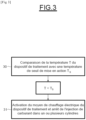
- the temperature T of the combustion gas treatment device is compared with the actuation threshold temperature T S .
- the temperature of the catalyst is generally lower than its activation threshold temperature when the engine 1 is cold, which is particularly the case during start-up and the first seconds of operation of the latter.
- the heating means of the treatment device are activated in a step 30 and the fuel supply is cut off in one or more of cylinders 2, 3 and 4.
- the heating means 28 is activated by the control device 27 which cuts the injection of fuel into one of the cylinders, cylinder 2.
- the ignition of the spark plugs in the cylinders where the fuel injection is cut off is also cut off. Only the opening and closing of the intake 22 and exhaust 23 valves continue to operate normally.
- the air 10 injected into the intake duct 11 passes, via the cylinder 2, towards the exhaust duct 14 when the intake 22 and exhaust 23 valves open in accordance with normal operation. of the motor.
- the air can then be directed towards the treatment device 18.
- the fuel supply to all the cylinders 2, 3, 4 is restored when the processing device 18 reaches its temperature of activation threshold, from which it effectively treats the polluting emissions of engine 1.
- the opening of the intake 22 and exhaust 23 valves of the cylinders not supplied with fuel thus allows the passage of air towards the treatment device 18.
- This increase in the flow of air and its contact with the heating means 18 have the consequence of promoting heat exchange between the heating means 28, here a heating grid, and the catalyst monolith 18 which leads to a more rapid increase in the temperature of the processing device 18.
- the processing device 18, in in particular the monolith reaches its activation threshold temperature T S more quickly and the production of hydrocarbons is reduced. This results in a reduced emission of polluting gases.
- control method according to the invention is applicable both to direct injection and indirect injection engines.
- control device 27 may be capable of controlling the percentage of opening of the inlet 22 and exhaust 23 valves of the cylinders 2, 3, 4 whose fuel supply is cut off. In this way, the valves 22, 23 can be opened either totally or partially.
- control device 27 can be configured to control the stopping of the fuel supply in one or more of the cylinders according to a torque set point of the traction device.
- control device 27 calculates the torque setpoint of the traction device as a function of the speed of the traction device and the depression of an accelerator pedal determined beforehand.
- control device 27 may also be configured to control the distribution of the torque of the traction device to be supplied between an electric motor and the internal combustion engine, when the temperature of the treatment device is lower than the actuation threshold temperature.
- control device 27 cuts off the fuel supply to all of the cylinders 2, 3, 4 of the internal combustion engine 1 and the entire torque of the traction device is supplied by the electric motor, when the temperature of the treatment device is below the activation threshold temperature.
- the electric motor operates alone as long as the treatment device 18 is not active and capable of treating the pollutants emitted by the internal combustion engine in operation, and the torque of the traction device is ensured without emission of pollutants.
- control device 27 determines the difference between the temperature T of the treatment device and the activation threshold temperature T S and distributes the torque of the traction device to be supplied respectively by the electric motor and the internal combustion engine according to the determined temperature difference.
- the more the temperature T of the processing device 18 approaches its activation threshold temperature T S that is to say the more the determined temperature difference decreases, the more the torque to be supplied by the device traction will be allocated by the control device 27 to the internal combustion engine 1 which gradually restores the injection of fuel into the plurality of cylinders 2, 3, 4.
- the internal combustion engine 1 then starts gradually with an emission of pollutants thus minimized.
Landscapes
- Engineering & Computer Science (AREA)
- Chemical & Material Sciences (AREA)
- Combustion & Propulsion (AREA)
- Mechanical Engineering (AREA)
- General Engineering & Computer Science (AREA)
- Chemical Kinetics & Catalysis (AREA)
- Health & Medical Sciences (AREA)
- Toxicology (AREA)
- Transportation (AREA)
- Output Control And Ontrol Of Special Type Engine (AREA)
- Control Of Vehicle Engines Or Engines For Specific Uses (AREA)
- Electrical Control Of Air Or Fuel Supplied To Internal-Combustion Engine (AREA)
- Hybrid Electric Vehicles (AREA)
- Combined Controls Of Internal Combustion Engines (AREA)
- Exhaust Gas After Treatment (AREA)
- Automation & Control Theory (AREA)
Claims (13)
- Verfahren zur Steuerung einer Antriebsvorrichtung für ein einen Verbrennungsmotor (1) enthaltendes Kraftfahrzeug, wobei der Motor (1) eine Vielzahl von Zylindern (2, 3, 4), die je mit mindestens einem Lufteinlassventil (22), mindestens einem Auslassventil (23) der vom Verbrennungsmotor (1) erzeugten Abgase und einer Kraftstoffeinspritzdüse (6, 7, 8) versehen sind, und eine Verarbeitungsvorrichtung (18) der Abgase aufweist, die ausgehend von einer Anspringtemperatur (TS) aktiv ist, wobei die Verarbeitungsvorrichtung (18) dem Auslassventil (23) nachgelagert ist, wobei die Antriebsvorrichtung eine Steuervorrichtung (27) enthält, und die Temperatur (T) der Verarbeitungsvorrichtung (18) der Abgase mit einer Anspringschwellentemperatur (TS) verglichen wird (30), und so lange die Temperatur (T) der Verarbeitungsvorrichtung (18) der Abgase niedriger ist als die Schwellentemperatur (TS), die Kraftstoffversorgung in einem oder mehreren der Zylinder (2) des Motors (1) unterbrochen wird, dadurch gekennzeichnet, dass die Antriebsvorrichtung außerdem eine elektrische Heizeinrichtung (28) der Verarbeitungsvorrichtung (18) der Abgase enthält, und so lange die Temperatur (T) der Verarbeitungsvorrichtung (18) der Abgase niedriger ist als die Schwellentemperatur (TS), die Heizeinrichtung (28) der Verarbeitungsvorrichtung (18) der Abgase aktiviert wird (31) .
- Verfahren nach Anspruch 1, dadurch gekennzeichnet, dass die Steuervorrichtung (27) die folgenden Schritte durchführt:Bestimmung des Betriebszustands der Antriebsvorrichtung und des Herunterdrückens eines Gaspedals;Berechnung eines Drehmomentsollwerts der Antriebsvorrichtung abhängig vom bestimmten Betriebszustand der Antriebsvorrichtung und vom bestimmten Herunterdrücken des Pedals; unddie Steuerung des Sperrens der Kraftstoffversorgung eines oder mehrerer der Zylinder (2) abhängig vom berechneten Drehmomentsollwert der Antriebsvorrichtung.
- Verfahren nach einem der Ansprüche 1 oder 2, dadurch gekennzeichnet, dass es die Steuerung durch die Steuervorrichtung (27) des Öffnungsprozentsatzes der Einlass- (22) und Auslassventile (23) der Zylinder (2) enthält, deren Kraftstoffversorgung unterbrochen ist.
- Verfahren nach einem der vorhergehenden Ansprüche, dadurch gekennzeichnet, dass es die Verteilung durch die Steuervorrichtung (27) des zu liefernden Drehmoments der Antriebsvorrichtung zwischen einem Elektromotor der Antriebsvorrichtung und dem Verbrennungsmotor (1) enthält, wenn die Temperatur (T) der Verarbeitungsvorrichtung (18) niedriger ist als die Anspringschwellentemperatur (TS).
- Verfahren nach Anspruch 4, dadurch gekennzeichnet, dass die Steuervorrichtung (27) die Kraftstoffversorgung in der Einheit der Zylinder (2, 3, 4) des Verbrennungsmotor (1) unterbricht und die Gesamtheit des Drehmoments der Antriebsvorrichtung vom Elektromotor geliefert wird, wenn die Temperatur (T) der Verarbeitungsvorrichtung (18) niedriger ist als die Anspringschwellentemperatur (TS).
- Verfahren nach Anspruch 4 oder 5, dadurch gekennzeichnet, dass es die Bestimmung durch die Steuervorrichtung (27) der Abweichung zwischen der Temperatur (T) der Verarbeitungsvorrichtung (18) und der Anspringschwellentemperatur (TS) und die Verteilung des Drehmoments der Antriebsvorrichtung enthält, das vom Elektromotor bzw. vom Verbrennungsmotor (1) abhängig von der bestimmten Abweichung zu liefern ist.
- Antriebsvorrichtung für ein einen Verbrennungsmotor (1) enthaltendes Kraftfahrzeug, wobei der Motor (1) eine Vielzahl von Zylindern (2, 3, 4), die je mit mindestens einem Lufteinlassventil (22), mindestens einem Auslassventil (23) der vom Verbrennungsmotor (1) erzeugten Abgase und einer Kraftstoffeinspritzdüse (6, 7, 8) versehen sind, und eine Verarbeitungsvorrichtung (18) der Abgase aufweist, die ausgehend von einer Anspringtemperatur (TS) aktiv ist, wobei die Verarbeitungsvorrichtung (18) dem Auslassventil (23) nachgelagert ist, wobei die Antriebsvorrichtung außerdem einen Temperaturfühler (21), der konfiguriert ist, die Temperatur der Verarbeitungsvorrichtung (18) zu erfassen, und eine Steuervorrichtung (27) enthält, die konfiguriert ist, die Kraftstoffversorgung in einem oder mehreren der Zylinder (2) des Motors (1) zu unterbrechen, so lange die Temperatur (T) der Verarbeitungsvorrichtung (18) der Abgase niedriger ist als eine Anspringschwellentemperatur (TS), dadurch gekennzeichnet, dass sie eine elektrische Heizeinrichtung (28) der Verarbeitungsvorrichtung (18) enthält, wobei die Steuervorrichtung (27) konfiguriert ist, die Heizeinrichtung (28) der Verarbeitungsvorrichtung (18) zu aktivieren, so lange die Temperatur (T) der Verarbeitungsvorrichtung niedriger ist als eine Anspringschwellentemperatur (TS).
- Antriebsvorrichtung nach Anspruch 7, dadurch gekennzeichnet, dass die Steuervorrichtung konfiguriert ist, um:den Betriebszustand der Antriebsvorrichtung und des Herunterdrückens eines Gaspedals zu bestimmen;einen Drehmomentsollwert der Antriebsvorrichtung abhängig vom bestimmten Betriebszustand und vom bestimmten Herunterdrücken zu berechnen; unddas Sperren der Kraftstoffversorgung in einem oder mehreren der Zylinder (2) abhängig vom berechneten Drehmomentsollwert der Antriebsvorrichtung zu steuern.
- Antriebsvorrichtung nach Anspruch 7 oder 8, dadurch gekennzeichnet, dass die Steuervorrichtung (27) geeignet ist, den Öffnungsprozentsatz der Einlass- (22) und Auslassventile (23) der Zylinder (2) zu steuern, deren Kraftstoffversorgung unterbrochen ist.
- Antriebsvorrichtung nach einem der Ansprüche 7 bis 9, dadurch gekennzeichnet, dass sie einen Elektromotor enthält, wobei die Steuervorrichtung (27) konfiguriert ist, den Antrieb des Kraftfahrzeugs mindestens zum Teil von einem Elektromotor anzuordnen, so lange die Temperatur (T) der Verarbeitungsvorrichtung (18) niedriger ist als die Anspringschwellentemperatur (TS).
- Antriebsvorrichtung nach Anspruch 10, dadurch gekennzeichnet, dass die Steuervorrichtung (27) konfiguriert ist, die Kraftstoffversorgung in der Einheit der Zylinder (2, 3, 4) des Verbrennungsmotors (1) zu unterbrechen und das Liefern der Gesamtheit des Drehmoments der Antriebsvorrichtung vom Elektromotor anzuordnen, wenn die Temperatur (T) der Verarbeitungsvorrichtung (18) niedriger ist als die Anspringschwellentemperatur (TS).
- Antriebsvorrichtung nach Anspruch 10 oder 11, dadurch gekennzeichnet, dass die Steuervorrichtung (27) konfiguriert ist, die Abweichung zwischen der Temperatur (T) der Verarbeitungsvorrichtung (18) und der Anspringschwellentemperatur (TS) zu bestimmen und die Verteilung des vom Elektromotor bzw. vom Verbrennungsmotor (1) zu liefernden Drehmoments abhängig von der bestimmten Abweichung zu bestimmen.
- Kraftfahrzeug, das eine Antriebsvorrichtung nach einem der Ansprüche 7 bis 12 enthält.
Applications Claiming Priority (2)
| Application Number | Priority Date | Filing Date | Title |
|---|---|---|---|
| FR1871888A FR3088959B1 (fr) | 2018-11-27 | 2018-11-27 | Procédé de commande d’un dispositif de traction pour véhicule automobile comprenant un dispositif de traitement des gaz de combustion chauffé électriquement |
| PCT/EP2019/082361 WO2020109204A1 (fr) | 2018-11-27 | 2019-11-25 | Procédé de commande d'un dispositif de traction pour véhicule automobile comprenant un dispositif de traitement des gaz de combustion chauffé électriquement |
Publications (2)
| Publication Number | Publication Date |
|---|---|
| EP3887660A1 EP3887660A1 (de) | 2021-10-06 |
| EP3887660B1 true EP3887660B1 (de) | 2023-08-30 |
Family
ID=66218196
Family Applications (1)
| Application Number | Title | Priority Date | Filing Date |
|---|---|---|---|
| EP19805706.9A Active EP3887660B1 (de) | 2018-11-27 | 2019-11-25 | Steuerungsverfahren einer antriebsvorrichtung für ein automobiles fahrzeug beinhaltend ein elektrisch beheiztes abgasnachbehandlungssystem |
Country Status (7)
| Country | Link |
|---|---|
| US (1) | US11879376B2 (de) |
| EP (1) | EP3887660B1 (de) |
| JP (1) | JP2022507964A (de) |
| KR (1) | KR20210094621A (de) |
| CN (1) | CN113167164B (de) |
| FR (1) | FR3088959B1 (de) |
| WO (1) | WO2020109204A1 (de) |
Families Citing this family (1)
| Publication number | Priority date | Publication date | Assignee | Title |
|---|---|---|---|---|
| WO2023104341A1 (en) * | 2021-12-08 | 2023-06-15 | Eaton Intelligent Power Limited | Aftertreatment heat up strategies in vehicles with hybrid powertrains |
Family Cites Families (20)
| Publication number | Priority date | Publication date | Assignee | Title |
|---|---|---|---|---|
| DE69309767T2 (de) * | 1992-05-15 | 1997-10-23 | Mitsubishi Motors Corp | Verfahren zum Betrieb eines hybriden Fahrzeugs |
| US5357752A (en) | 1993-08-17 | 1994-10-25 | Exxon Research And Engineering Company | Control of secondary air to an electrically heated catalyst using feedback control |
| US6018694A (en) * | 1996-07-30 | 2000-01-25 | Denso Corporation | Controller for hybrid vehicle |
| FR2758160B1 (fr) * | 1997-01-06 | 1999-03-26 | Renault | Procede de gestion d'un moteur a combustion interne et moteur correspondant |
| JP4080620B2 (ja) * | 1998-12-11 | 2008-04-23 | 本田技研工業株式会社 | 気筒休止エンジンの排気ガス浄化装置 |
| JP3705361B2 (ja) * | 2002-01-31 | 2005-10-12 | 三菱自動車工業株式会社 | ハイブリッド車両の制御装置 |
| US6668546B2 (en) * | 2002-02-19 | 2003-12-30 | General Motors Corporation | Utilization of air-assisted direct injection, cylinder deactivation and camshaft phasing for improved catalytic converter light-off in internal combustion engines |
| US6907725B2 (en) * | 2003-04-30 | 2005-06-21 | General Motors Corporation | Method for reducing engine exhaust emissions |
| JP4758391B2 (ja) * | 2007-05-09 | 2011-08-24 | トヨタ自動車株式会社 | 排ガス浄化用触媒の再生装置及び再生方法 |
| JP2009035117A (ja) * | 2007-08-01 | 2009-02-19 | Nissan Motor Co Ltd | ハイブリッド車両における内燃機関の排気浄化制御装置 |
| US8104269B2 (en) * | 2008-11-11 | 2012-01-31 | GM Global Technology Operations LLC | Catalytic combustor strategy using HC adsorber |
| DE102008063449A1 (de) * | 2008-12-17 | 2010-07-01 | Dr. Ing. H.C. F. Porsche Aktiengesellschaft | Verfahren zum Betreiben eines Hybridantriebs |
| JP2011196231A (ja) * | 2010-03-18 | 2011-10-06 | Toyota Motor Corp | 内燃機関の触媒ヒータ制御装置 |
| US8756924B2 (en) * | 2010-05-19 | 2014-06-24 | GM Global Technology Operations LLC | Hybrid catalyst convective preheating system |
| US8475333B2 (en) * | 2011-05-05 | 2013-07-02 | GM Global Technology Operations LLC | Method and apparatus for effecting light-off of a catalytic converter in a hybrid powertrain system |
| FR2995466B1 (fr) * | 2012-09-13 | 2014-08-29 | Renault Sa | Systeme et procede de gestion de l'alimentation electrique d'au moins un equipement au redemarrage automatique d'un moteur thermique de vehicule |
| KR101628508B1 (ko) * | 2014-10-30 | 2016-06-08 | 현대자동차주식회사 | 차량의 가속토크 제어 장치 및 방법 |
| JP6319241B2 (ja) * | 2015-09-11 | 2018-05-09 | マツダ株式会社 | 発電機駆動用エンジン搭載の自動車 |
| US9925974B2 (en) * | 2016-04-26 | 2018-03-27 | Ford Global Technologies, Llc | System and methods for improving fuel economy |
| US11199118B2 (en) * | 2018-08-27 | 2021-12-14 | Ford Global Technologies, Llc | Systems and methods for reducing cold start emissions for autonomous vehicles |
-
2018
- 2018-11-27 FR FR1871888A patent/FR3088959B1/fr active Active
-
2019
- 2019-11-25 US US17/285,970 patent/US11879376B2/en active Active
- 2019-11-25 JP JP2021529301A patent/JP2022507964A/ja active Pending
- 2019-11-25 KR KR1020217019747A patent/KR20210094621A/ko not_active Application Discontinuation
- 2019-11-25 CN CN201980077875.2A patent/CN113167164B/zh active Active
- 2019-11-25 WO PCT/EP2019/082361 patent/WO2020109204A1/fr unknown
- 2019-11-25 EP EP19805706.9A patent/EP3887660B1/de active Active
Also Published As
| Publication number | Publication date |
|---|---|
| CN113167164A (zh) | 2021-07-23 |
| KR20210094621A (ko) | 2021-07-29 |
| FR3088959A1 (fr) | 2020-05-29 |
| JP2022507964A (ja) | 2022-01-18 |
| FR3088959B1 (fr) | 2020-12-11 |
| US20210339734A1 (en) | 2021-11-04 |
| US11879376B2 (en) | 2024-01-23 |
| CN113167164B (zh) | 2023-08-15 |
| EP3887660A1 (de) | 2021-10-06 |
| WO2020109204A1 (fr) | 2020-06-04 |
Similar Documents
| Publication | Publication Date | Title |
|---|---|---|
| FR2899932A1 (fr) | Procede et dispositif de controle de la regeneration d'un systeme de depollution | |
| FR3064683B1 (fr) | Procede de controle d'un moteur a allumage commande suralimente avec recirculation partielle des gaz d'echappement, et dispositif de motorisation associe | |
| EP3887660B1 (de) | Steuerungsverfahren einer antriebsvorrichtung für ein automobiles fahrzeug beinhaltend ein elektrisch beheiztes abgasnachbehandlungssystem | |
| FR3072418A1 (fr) | Procede de controle d'un moteur a combustion interne a allumage commande, a l'etat non allume | |
| FR3051227A1 (fr) | Procede de commande d'un moteur a allumage commande | |
| EP2078839B1 (de) | Strategie der Schnellerhitzung, um die Deaktivierung eines Oxidationskatalysators eines Dieselmotors zu kompensieren | |
| FR3109798A1 (fr) | Procédé de gestion de l’amorçage d’un dispositif de post-traitement des gaz d’échappement de véhicule automobile | |
| FR3020837A1 (fr) | Procede de gestion d'un moteur a combustion interne de vehicule automobile en mode de poussee pour reduire la consommation de carburant et les emissions | |
| FR3088957A1 (fr) | Dispositif et procédé de commande de la régénération d'un filtre à particules d'une ligne d'échappement d'un moteur à combustion interne | |
| EP1709312B1 (de) | Verfahren zur steuerung der einlassventile eines verbrennungsmotors | |
| FR3072726A3 (fr) | Procede de controle d'un moteur a combustion interne suralimente a allumage par compression, a l'etat non allume | |
| FR2926518A1 (fr) | Procede de commande d'un moteur hybride et moteur correspondant | |
| FR2902832A1 (fr) | Procede de pilotage d'un moteur a combustion interne comportant des moyens de filtrage lors d'une phase de regeneration de ces moyens de filtrage et pour un regime au ralenti | |
| FR2867514A1 (fr) | Procede et dispositif de gestion d'un moteur a combustion interne | |
| EP2562400A1 (de) | Verfahren zur Regeneration eines Partikelfilters einer Brennkraftmaschine | |
| WO2024079298A1 (fr) | Procédé de chauffage d'un catalyseur dans un véhicule à motirisation hybride | |
| WO2022223893A1 (fr) | Moteur a combustion interne equipe d'un dispositif d'injection d'air a l'echappement | |
| WO2022184480A1 (fr) | Procédé et système de commande d'un moteur à combustion interne à allumage commandé en phase de levé de pied. | |
| FR3085717A1 (fr) | Ensemble moteur a dispositif de chauffage electrique des gaz | |
| FR3122699A1 (fr) | Moteur à combustion interne | |
| FR2927657A3 (fr) | Alimentation en carburant du systeme d'admission de reducteurs dans l'echappement et dispositif de depollution des gaz d'echappement d'un vehicule automobile. | |
| FR2836514A1 (fr) | Procede et dispositif de commande du fonctionnement d'un moteur a combustion interne | |
| FR2919668A1 (fr) | Moteur thermique comportant un dispositif d'injection d'air par l'echappement | |
| EP2444640A1 (de) | Regelverfahren für die Regeneration eines Partikelfilters | |
| FR3086333A1 (fr) | Procede de pilotage d’un dispositif de chauffage d’un catalyseur de reduction selective des oxydes d’azote |
Legal Events
| Date | Code | Title | Description |
|---|---|---|---|
| STAA | Information on the status of an ep patent application or granted ep patent |
Free format text: STATUS: UNKNOWN |
|
| STAA | Information on the status of an ep patent application or granted ep patent |
Free format text: STATUS: THE INTERNATIONAL PUBLICATION HAS BEEN MADE |
|
| PUAI | Public reference made under article 153(3) epc to a published international application that has entered the european phase |
Free format text: ORIGINAL CODE: 0009012 |
|
| STAA | Information on the status of an ep patent application or granted ep patent |
Free format text: STATUS: REQUEST FOR EXAMINATION WAS MADE |
|
| 17P | Request for examination filed |
Effective date: 20210520 |
|
| AK | Designated contracting states |
Kind code of ref document: A1 Designated state(s): AL AT BE BG CH CY CZ DE DK EE ES FI FR GB GR HR HU IE IS IT LI LT LU LV MC MK MT NL NO PL PT RO RS SE SI SK SM TR |
|
| DAV | Request for validation of the european patent (deleted) | ||
| DAX | Request for extension of the european patent (deleted) | ||
| RAP3 | Party data changed (applicant data changed or rights of an application transferred) |
Owner name: NISSAN MOTOR CO., LTD. Owner name: RENAULT S.A.S |
|
| RAP3 | Party data changed (applicant data changed or rights of an application transferred) |
Owner name: NISSAN MOTOR CO., LTD. Owner name: RENAULT S.A.S |
|
| GRAP | Despatch of communication of intention to grant a patent |
Free format text: ORIGINAL CODE: EPIDOSNIGR1 |
|
| STAA | Information on the status of an ep patent application or granted ep patent |
Free format text: STATUS: GRANT OF PATENT IS INTENDED |
|
| INTG | Intention to grant announced |
Effective date: 20230314 |
|
| GRAS | Grant fee paid |
Free format text: ORIGINAL CODE: EPIDOSNIGR3 |
|
| GRAA | (expected) grant |
Free format text: ORIGINAL CODE: 0009210 |
|
| STAA | Information on the status of an ep patent application or granted ep patent |
Free format text: STATUS: THE PATENT HAS BEEN GRANTED |
|
| AK | Designated contracting states |
Kind code of ref document: B1 Designated state(s): AL AT BE BG CH CY CZ DE DK EE ES FI FR GB GR HR HU IE IS IT LI LT LU LV MC MK MT NL NO PL PT RO RS SE SI SK SM TR |
|
| REG | Reference to a national code |
Ref country code: GB Ref legal event code: FG4D Free format text: NOT ENGLISH |
|
| REG | Reference to a national code |
Ref country code: CH Ref legal event code: EP |
|
| REG | Reference to a national code |
Ref country code: DE Ref legal event code: R096 Ref document number: 602019036299 Country of ref document: DE |
|
| REG | Reference to a national code |
Ref country code: IE Ref legal event code: FG4D Free format text: LANGUAGE OF EP DOCUMENT: FRENCH |
|
| REG | Reference to a national code |
Ref country code: LT Ref legal event code: MG9D |
|
| REG | Reference to a national code |
Ref country code: NL Ref legal event code: MP Effective date: 20230830 |
|
| REG | Reference to a national code |
Ref country code: AT Ref legal event code: MK05 Ref document number: 1605713 Country of ref document: AT Kind code of ref document: T Effective date: 20230830 |
|
| PG25 | Lapsed in a contracting state [announced via postgrant information from national office to epo] |
Ref country code: GR Free format text: LAPSE BECAUSE OF FAILURE TO SUBMIT A TRANSLATION OF THE DESCRIPTION OR TO PAY THE FEE WITHIN THE PRESCRIBED TIME-LIMIT Effective date: 20231201 |
|
| PGFP | Annual fee paid to national office [announced via postgrant information from national office to epo] |
Ref country code: GB Payment date: 20231123 Year of fee payment: 5 |
|
| PG25 | Lapsed in a contracting state [announced via postgrant information from national office to epo] |
Ref country code: IS Free format text: LAPSE BECAUSE OF FAILURE TO SUBMIT A TRANSLATION OF THE DESCRIPTION OR TO PAY THE FEE WITHIN THE PRESCRIBED TIME-LIMIT Effective date: 20231230 |
|
| PG25 | Lapsed in a contracting state [announced via postgrant information from national office to epo] |
Ref country code: SE Free format text: LAPSE BECAUSE OF FAILURE TO SUBMIT A TRANSLATION OF THE DESCRIPTION OR TO PAY THE FEE WITHIN THE PRESCRIBED TIME-LIMIT Effective date: 20230830 Ref country code: RS Free format text: LAPSE BECAUSE OF FAILURE TO SUBMIT A TRANSLATION OF THE DESCRIPTION OR TO PAY THE FEE WITHIN THE PRESCRIBED TIME-LIMIT Effective date: 20230830 Ref country code: NO Free format text: LAPSE BECAUSE OF FAILURE TO SUBMIT A TRANSLATION OF THE DESCRIPTION OR TO PAY THE FEE WITHIN THE PRESCRIBED TIME-LIMIT Effective date: 20231130 Ref country code: LV Free format text: LAPSE BECAUSE OF FAILURE TO SUBMIT A TRANSLATION OF THE DESCRIPTION OR TO PAY THE FEE WITHIN THE PRESCRIBED TIME-LIMIT Effective date: 20230830 Ref country code: LT Free format text: LAPSE BECAUSE OF FAILURE TO SUBMIT A TRANSLATION OF THE DESCRIPTION OR TO PAY THE FEE WITHIN THE PRESCRIBED TIME-LIMIT Effective date: 20230830 Ref country code: IS Free format text: LAPSE BECAUSE OF FAILURE TO SUBMIT A TRANSLATION OF THE DESCRIPTION OR TO PAY THE FEE WITHIN THE PRESCRIBED TIME-LIMIT Effective date: 20231230 Ref country code: HR Free format text: LAPSE BECAUSE OF FAILURE TO SUBMIT A TRANSLATION OF THE DESCRIPTION OR TO PAY THE FEE WITHIN THE PRESCRIBED TIME-LIMIT Effective date: 20230830 Ref country code: GR Free format text: LAPSE BECAUSE OF FAILURE TO SUBMIT A TRANSLATION OF THE DESCRIPTION OR TO PAY THE FEE WITHIN THE PRESCRIBED TIME-LIMIT Effective date: 20231201 Ref country code: FI Free format text: LAPSE BECAUSE OF FAILURE TO SUBMIT A TRANSLATION OF THE DESCRIPTION OR TO PAY THE FEE WITHIN THE PRESCRIBED TIME-LIMIT Effective date: 20230830 Ref country code: AT Free format text: LAPSE BECAUSE OF FAILURE TO SUBMIT A TRANSLATION OF THE DESCRIPTION OR TO PAY THE FEE WITHIN THE PRESCRIBED TIME-LIMIT Effective date: 20230830 |
|
| PGFP | Annual fee paid to national office [announced via postgrant information from national office to epo] |
Ref country code: FR Payment date: 20231120 Year of fee payment: 5 Ref country code: DE Payment date: 20231121 Year of fee payment: 5 |
|
| PG25 | Lapsed in a contracting state [announced via postgrant information from national office to epo] |
Ref country code: PL Free format text: LAPSE BECAUSE OF FAILURE TO SUBMIT A TRANSLATION OF THE DESCRIPTION OR TO PAY THE FEE WITHIN THE PRESCRIBED TIME-LIMIT Effective date: 20230830 Ref country code: NL Free format text: LAPSE BECAUSE OF FAILURE TO SUBMIT A TRANSLATION OF THE DESCRIPTION OR TO PAY THE FEE WITHIN THE PRESCRIBED TIME-LIMIT Effective date: 20230830 |
|
| PG25 | Lapsed in a contracting state [announced via postgrant information from national office to epo] |
Ref country code: ES Free format text: LAPSE BECAUSE OF FAILURE TO SUBMIT A TRANSLATION OF THE DESCRIPTION OR TO PAY THE FEE WITHIN THE PRESCRIBED TIME-LIMIT Effective date: 20230830 |
|
| PG25 | Lapsed in a contracting state [announced via postgrant information from national office to epo] |
Ref country code: SM Free format text: LAPSE BECAUSE OF FAILURE TO SUBMIT A TRANSLATION OF THE DESCRIPTION OR TO PAY THE FEE WITHIN THE PRESCRIBED TIME-LIMIT Effective date: 20230830 Ref country code: RO Free format text: LAPSE BECAUSE OF FAILURE TO SUBMIT A TRANSLATION OF THE DESCRIPTION OR TO PAY THE FEE WITHIN THE PRESCRIBED TIME-LIMIT Effective date: 20230830 Ref country code: ES Free format text: LAPSE BECAUSE OF FAILURE TO SUBMIT A TRANSLATION OF THE DESCRIPTION OR TO PAY THE FEE WITHIN THE PRESCRIBED TIME-LIMIT Effective date: 20230830 Ref country code: EE Free format text: LAPSE BECAUSE OF FAILURE TO SUBMIT A TRANSLATION OF THE DESCRIPTION OR TO PAY THE FEE WITHIN THE PRESCRIBED TIME-LIMIT Effective date: 20230830 Ref country code: DK Free format text: LAPSE BECAUSE OF FAILURE TO SUBMIT A TRANSLATION OF THE DESCRIPTION OR TO PAY THE FEE WITHIN THE PRESCRIBED TIME-LIMIT Effective date: 20230830 Ref country code: CZ Free format text: LAPSE BECAUSE OF FAILURE TO SUBMIT A TRANSLATION OF THE DESCRIPTION OR TO PAY THE FEE WITHIN THE PRESCRIBED TIME-LIMIT Effective date: 20230830 Ref country code: SK Free format text: LAPSE BECAUSE OF FAILURE TO SUBMIT A TRANSLATION OF THE DESCRIPTION OR TO PAY THE FEE WITHIN THE PRESCRIBED TIME-LIMIT Effective date: 20230830 Ref country code: PT Free format text: LAPSE BECAUSE OF FAILURE TO SUBMIT A TRANSLATION OF THE DESCRIPTION OR TO PAY THE FEE WITHIN THE PRESCRIBED TIME-LIMIT Effective date: 20240102 |
|
| PG25 | Lapsed in a contracting state [announced via postgrant information from national office to epo] |
Ref country code: IT Free format text: LAPSE BECAUSE OF FAILURE TO SUBMIT A TRANSLATION OF THE DESCRIPTION OR TO PAY THE FEE WITHIN THE PRESCRIBED TIME-LIMIT Effective date: 20230830 |
|
| REG | Reference to a national code |
Ref country code: DE Ref legal event code: R097 Ref document number: 602019036299 Country of ref document: DE |
|
| REG | Reference to a national code |
Ref country code: CH Ref legal event code: PL |
|
| PG25 | Lapsed in a contracting state [announced via postgrant information from national office to epo] |
Ref country code: MC Free format text: LAPSE BECAUSE OF FAILURE TO SUBMIT A TRANSLATION OF THE DESCRIPTION OR TO PAY THE FEE WITHIN THE PRESCRIBED TIME-LIMIT Effective date: 20230830 |
|
| PLBE | No opposition filed within time limit |
Free format text: ORIGINAL CODE: 0009261 |
|
| STAA | Information on the status of an ep patent application or granted ep patent |
Free format text: STATUS: NO OPPOSITION FILED WITHIN TIME LIMIT |
|
| PG25 | Lapsed in a contracting state [announced via postgrant information from national office to epo] |
Ref country code: LU Free format text: LAPSE BECAUSE OF NON-PAYMENT OF DUE FEES Effective date: 20231125 |
|
| PG25 | Lapsed in a contracting state [announced via postgrant information from national office to epo] |
Ref country code: CH Free format text: LAPSE BECAUSE OF NON-PAYMENT OF DUE FEES Effective date: 20231130 |
|
| PG25 | Lapsed in a contracting state [announced via postgrant information from national office to epo] |
Ref country code: MC Free format text: LAPSE BECAUSE OF FAILURE TO SUBMIT A TRANSLATION OF THE DESCRIPTION OR TO PAY THE FEE WITHIN THE PRESCRIBED TIME-LIMIT Effective date: 20230830 Ref country code: LU Free format text: LAPSE BECAUSE OF NON-PAYMENT OF DUE FEES Effective date: 20231125 Ref country code: CH Free format text: LAPSE BECAUSE OF NON-PAYMENT OF DUE FEES Effective date: 20231130 Ref country code: SI Free format text: LAPSE BECAUSE OF FAILURE TO SUBMIT A TRANSLATION OF THE DESCRIPTION OR TO PAY THE FEE WITHIN THE PRESCRIBED TIME-LIMIT Effective date: 20230830 |
|
| REG | Reference to a national code |
Ref country code: BE Ref legal event code: MM Effective date: 20231130 |
|
| 26N | No opposition filed |
Effective date: 20240603 |