EP3886965B1 - Befestigungsvorrichtung für eine vorstehende mund- oder nasenvorrichtung - Google Patents
Befestigungsvorrichtung für eine vorstehende mund- oder nasenvorrichtung Download PDFInfo
- Publication number
- EP3886965B1 EP3886965B1 EP19816403.0A EP19816403A EP3886965B1 EP 3886965 B1 EP3886965 B1 EP 3886965B1 EP 19816403 A EP19816403 A EP 19816403A EP 3886965 B1 EP3886965 B1 EP 3886965B1
- Authority
- EP
- European Patent Office
- Prior art keywords
- bridge portion
- securement device
- patient
- oral
- anchor portion
- Prior art date
- Legal status (The legal status is an assumption and is not a legal conclusion. Google has not performed a legal analysis and makes no representation as to the accuracy of the status listed.)
- Active
Links
Images


Classifications
-
- A—HUMAN NECESSITIES
- A61—MEDICAL OR VETERINARY SCIENCE; HYGIENE
- A61M—DEVICES FOR INTRODUCING MEDIA INTO, OR ONTO, THE BODY; DEVICES FOR TRANSDUCING BODY MEDIA OR FOR TAKING MEDIA FROM THE BODY; DEVICES FOR PRODUCING OR ENDING SLEEP OR STUPOR
- A61M16/00—Devices for influencing the respiratory system of patients by gas treatment, e.g. ventilators; Tracheal tubes
- A61M16/04—Tracheal tubes
- A61M16/0488—Mouthpieces; Means for guiding, securing or introducing the tubes
- A61M16/0497—Tube stabilizer
-
- A—HUMAN NECESSITIES
- A61—MEDICAL OR VETERINARY SCIENCE; HYGIENE
- A61M—DEVICES FOR INTRODUCING MEDIA INTO, OR ONTO, THE BODY; DEVICES FOR TRANSDUCING BODY MEDIA OR FOR TAKING MEDIA FROM THE BODY; DEVICES FOR PRODUCING OR ENDING SLEEP OR STUPOR
- A61M16/00—Devices for influencing the respiratory system of patients by gas treatment, e.g. ventilators; Tracheal tubes
- A61M16/06—Respiratory or anaesthetic masks
- A61M16/0666—Nasal cannulas or tubing
-
- A—HUMAN NECESSITIES
- A61—MEDICAL OR VETERINARY SCIENCE; HYGIENE
- A61M—DEVICES FOR INTRODUCING MEDIA INTO, OR ONTO, THE BODY; DEVICES FOR TRANSDUCING BODY MEDIA OR FOR TAKING MEDIA FROM THE BODY; DEVICES FOR PRODUCING OR ENDING SLEEP OR STUPOR
- A61M16/00—Devices for influencing the respiratory system of patients by gas treatment, e.g. ventilators; Tracheal tubes
- A61M16/06—Respiratory or anaesthetic masks
- A61M16/0683—Holding devices therefor
- A61M16/0688—Holding devices therefor by means of an adhesive
-
- A—HUMAN NECESSITIES
- A61—MEDICAL OR VETERINARY SCIENCE; HYGIENE
- A61M—DEVICES FOR INTRODUCING MEDIA INTO, OR ONTO, THE BODY; DEVICES FOR TRANSDUCING BODY MEDIA OR FOR TAKING MEDIA FROM THE BODY; DEVICES FOR PRODUCING OR ENDING SLEEP OR STUPOR
- A61M25/00—Catheters; Hollow probes
- A61M25/01—Introducing, guiding, advancing, emplacing or holding catheters
- A61M25/02—Holding devices, e.g. on the body
- A61M2025/0213—Holding devices, e.g. on the body where the catheter is attached by means specifically adapted to a part of the human body
- A61M2025/022—Holding devices, e.g. on the body where the catheter is attached by means specifically adapted to a part of the human body specifically adapted for the mouth
-
- A—HUMAN NECESSITIES
- A61—MEDICAL OR VETERINARY SCIENCE; HYGIENE
- A61M—DEVICES FOR INTRODUCING MEDIA INTO, OR ONTO, THE BODY; DEVICES FOR TRANSDUCING BODY MEDIA OR FOR TAKING MEDIA FROM THE BODY; DEVICES FOR PRODUCING OR ENDING SLEEP OR STUPOR
- A61M25/00—Catheters; Hollow probes
- A61M25/01—Introducing, guiding, advancing, emplacing or holding catheters
- A61M25/02—Holding devices, e.g. on the body
- A61M2025/0213—Holding devices, e.g. on the body where the catheter is attached by means specifically adapted to a part of the human body
- A61M2025/0226—Holding devices, e.g. on the body where the catheter is attached by means specifically adapted to a part of the human body specifically adapted for the nose
-
- A—HUMAN NECESSITIES
- A61—MEDICAL OR VETERINARY SCIENCE; HYGIENE
- A61M—DEVICES FOR INTRODUCING MEDIA INTO, OR ONTO, THE BODY; DEVICES FOR TRANSDUCING BODY MEDIA OR FOR TAKING MEDIA FROM THE BODY; DEVICES FOR PRODUCING OR ENDING SLEEP OR STUPOR
- A61M25/00—Catheters; Hollow probes
- A61M25/01—Introducing, guiding, advancing, emplacing or holding catheters
- A61M25/02—Holding devices, e.g. on the body
- A61M2025/0266—Holding devices, e.g. on the body using pads, patches, tapes or the like
Definitions
- the present invention relates to a securement device for a protruding oral or nasal device including but not limited to an endotracheal tube, and in particular, to a securement device that comprises a continuous strip with an adhesive for affixing the strip to a patient.
- Endotracheal intubation is an important procedure in both anaesthetized and critically ill patients. Endotracheal tube displacement is one of the leading causes for airway relates complications. Securing the endotracheal tube, therefore, is critically important in preventing accidental extubation, which can be life threatening.
- Rates of unintentional extubation are found to range from 1.6% to 21% between anaesthesia and intensive care.
- ICU intensive care unit
- US patent application publication US-A-2010/0199997 (McInnes et al. ) describes a tracheal tube support apparatus that includes a pair of oppositely disposed adhesively mountable flanges for releasably mounting to the face of the patient. A pair of adhesive-backed wings is provided for releasable mounting to a portion of the tracheal tube once intubated.
- US patent 5308339 describes an example of a clamp for adapted for use with so called Hepburn type locks for catheter needles. The clamp includes a one piece substrate having a medical grade double sided adhesive base.
- An endotracheal tube is not the only device for which secure tube fixation is important. Secure fixation is also required for protruding oral or nasal devices such as supraglottic airways, oral monitoring devices such and naso-gastric tubes. It is an object of certain embodiments of the present invention to provide a securement device for a protruding oral or nasal device that overcomes at least some advantages associated with the prior art. It is an object of certain embodiments of the present invention to provide an alternative securement device for a protruding oral or nasal device relative to the prior art.
- a securement device for a protruding oral or nasal device comprising a continuous strip extending along a longitudinal axis between a first end and a second end, the continuous strip having:
- first anchor portion and the second anchor portion are offset from one another relative to the longitudinal axis.
- the first bridge portion may be substantially aligned with the longitudinal axis.
- the securement device may comprise a third bridge portion disposed between the second bridge portion and the second anchor portion, wherein the third bridge portion may be substantially aligned with the longitudinal axis.
- Either or both of the first anchor portion and second anchor portion may include a plurality of limbs.
- the plurality of limbs may comprise a pair of limbs extending from one another, where the pair of limbs may form a V-shape.
- the pair of limbs may form an intersection angle of between 70° and 110°.
- the strip may have a length along the longitudinal axis between 15 cm and 45 cm, and optionally about 30 cm.
- the first bridge portion may extend along a length between 1 cm and 4 cm, and optionally about 2 cm.
- the second bridge portion may extend along a length between 1 cm and 4 cm, and optionally about 2 cm.
- the second bridge portion may extend at an angle of between 10° and 80°, and optionally about 45° relative to the longitudinal axis.
- the adhesive is provided on a back side of the strip.
- the adhesive may be provided in selected regions of the back side of the strip. Alternatively, the adhesive may be provided substantially over the entire back side of the strip.
- the adhesive may comprise multiple adhesives or an adhesive having varying strengths across the strip.
- kits comprising a packaging containing a securement device as defined above.
- the securement device may be in a sterile state in the packaging prior to opening of the packaging.
- an assembly comprising an oral or nasal device and a securement device as defined above, wherein the securement device is wound around the oral or nasal device such that the first anchor portion and the second anchor portion extend from opposite sides of the oral or nasal device.
- the second bridge portion of the securement device may be wound around the oral or nasal device.
- a securement device to a protruding oral or nasal device and a patient comprising:
- winding the securement device around the tube may comprise winding the second bridge portion around the oral or nasal device.
- the securement device may be wound around the oral or nasal device and the first anchor portion may be adhered to the patient so that the first bridge portion leads away from the first anchor portion towards the lips of the patient.
- first anchor portion and second anchor portion when either or both of the first anchor portion and second anchor portion include a plurality of limbs, a first limb of the plurality of limbs may be adhered in the region of the cheek bone of the patient and a second limb of the plurality of limbs may be adhered in the region of the jaw bone of the patient.
- a securement device 10 is shown in Figure 1 .
- the securement device 10 is suitable for the securement of a protruding oral or nasal device (not shown in Figure 1 ).
- the securement device 10 comprises a strip 12 that extends along a longitudinal axis 100 between a first end 12a and a second end 12b.
- An adhesive (not visible in the Figures) is provided on a back side of the strip 12 for affixing the strip 12 to a patient.
- the strip 12 includes a first anchor portion 14 at the first end 12a and a second anchor portion 26 at the second end 12b.
- the strip 12 includes a first bridge portion 20, a second bridge portion 22 and a third bridge portion 24. More specifically, the first bridge portion 20 is disposed between the first anchor portion 14 and the second bridge portion 22, the second bridge portion 22 is disposed between the first bridge portion 20 and the third bridge portion 24, and the third bridge portion 24 is disposed between the second bridge portion 22 and the second anchor portion 26.
- each of the first bridge portion 20 and the third bridge portion 24 is substantially parallel to the longitudinal axis 100 (and one another).
- the second bridge portion 22 extends at an inclined angle ⁇ relative to the longitudinal axis 100 and each of the first bridge portion 20 and the third bridge portion 24.
- the first anchor portion 14 and the second anchor portion 26 are offset from one another relative to the longitudinal axis 100. That is, the first anchor portion 14 extends from the longitudinal axis 100 by an amount that differs from the amount that the second anchor portion 26 extends from the longitudinal axis 100 in the same direction.
- the strip 12 has a length L1 (taken along its longitudinal axis 100 between the first end 12a and second end 12b).
- the first bridge portion 20 has a length L2
- the second bridge portion 22 extends along a length L3
- the third bridge portion 24 extends along a length L4.
- L1 is between 15 cm and 45 cm and is optionally around 30 cm
- L2 is between 1 cm and 4 cm and is optionally around 2 cm
- L3 is between 1 cm and 4 cm and is optionally around 2 cm
- L4 is between 4 cm and 12 cm and is optionally around 8 cm.
- the inclination angle ⁇ of the second bridge portion 22 relative to the longitudinal axis 100 is between 10° and 80° and is optionally around 45°. Notwithstanding the above mentioned example lengths and angles, embodiments of the present invention may encompass other lengths and angles.
- the first anchor portion 14 comprises a first limb 16 and a second limb 18 that extend from one another in a V-shape and form an intersection angle ⁇ .
- the intersection angle ⁇ may be between 70° and 110° and may optionally be around 90°.
- the first limb 16 is configured to attach to the face of a patient in the region of the patient's cheek bone whilst the second limb 18 is configured to attach to the face of the patient face in the region of the jaw bone.
- the relative lengths of the first limb 16 and second limb 18 and the magnitude of the intersection angle ⁇ may therefore be configured so that the first anchor portion 14 may affix to the cheek and jaw bone of a certain patient or group of patients.
- first limb 16, second limb 18 and intersection angle ⁇ may be configured so that the first anchor portion 14 may affix to the cheek and jaw bone of an adult patient, whereas in other embodiments, the first limb 16, second limb 18 and intersection angle ⁇ may be configured so that the first anchor portion 14 may affix to the cheek and jaw bone of an infant patient.
- the second anchor portion 26 comprises a single limb that extends substantially parallel to the longitudinal axis 100 away from the third bridge portion 24.
- first anchor portion 14 and the second anchor portion 26 may include any number of limbs that extend from one another.
- the limbs may form a V-shape or other configuration, and the limbs may form any suitable intersection angle.
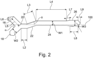
- FIG. 2 A non-limiting example of the relative lengths of the bridge portions and anchor portions of the securement device 10 is shown in Figure 2 .
- the width W1 of the third bridge portion 24 is shown as equal to 1.00 and all other dimensions in the example are provided relative to W1.
- the first bridge portion 20 has a length L2 equal to 1.25
- the second bridge portion has a length L3 equal to 2.00
- the third bridge portion has a length L4 equal to 6.50.
- the inclination angle ⁇ of the second bridge portion 22 relative to the longitudinal axis 100 is 18.97°.
- the first anchor portion 14 comprises a first limb 16 and a second limb 18.
- the first limb 16 and the second limb 18 have a width W2 equal to 1.25 and a length L5 equal to 2.25.
- the first and second limbs are each inclined at an angle of 135.20° relative to the longitudinal axis 100, as such, the intersection angle ⁇ is 89.60°.
- the first limb and second limb each have a tapered portion at the first end 12a of the strip 12, the tapered portions have a length L6 equal to 0.80.
- the second anchor portion comprises: a first portion with a length L7 equal to 0.75 which inclined at an angle of 9.59° relative to the longitudinal axis 100; a second portion substantially parallel to the longitudinal axis 100 with a length L8 equal to 1.75 and a width W3 equal to 1.25; and a third tapered portion at the second end 12b of the strip 12 that has a length L9 equal to 0.50 in the direction parallel to the longitudinal axis 100.
- the strip 12 is wound around a protruding oral or nasal device and is affixed to the patient's face by the adhesive on the back side of the strip 12.
- the protruding oral or nasal devices may include but are not limited to: endotracheal tubes such as standard endotracheal tubes, south facing endotracheal tubes, north facing endotracheal tubes, armoured or flexible endotracheal tubes, microlaryngoscopy tubes, double lumen endotracheal tubes, nasal endotracheal tubes and low pressure endotracheal tubes; supraglottic airways including standard laryngeal mask and flexible or armoured laryngeal masks; oral monitoring devices such as temperature probes and oesophogeal dopplers; and naso-gastric tubes.
- the protruding oral or nasal device may include any device that protrudes form a patient's oral or nasal cavity.
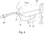
- Figures 3 and 4 show examples of an endotracheal tube 300 secured to a patient 200 using a securement device 10 in accordance with an embodiment of the present invention.
- the strip 12 is wound around the endotracheal tube 300 and is adhered to the face of the patient 200.
- the first limb 16 is adhered to the face of the patient 200 in the region of the cheek bone and the second limb 18 is adhered to the patient 200 in the region of the jaw bone.
- the first bridge portion 20 leads away from the first anchor portion 14 towards the lips 202 of the patient 200.
- the second bridge portion 22 is wound around the endotracheal tube 300.
- the second bridge portion 22 may wind around the endotracheal tube 300 such that the adhesive back side of the strip 12 is substantially affixed to the endotracheal tube 300 rather than the strip 12 itself. That is, the configuration of the second bridge portion 22 relative to the first bridge portion 20 may facilitate a secure winding of the strip 12 around the endotracheal tube 300 whilst avoiding winding of the strip 12 on itself. In particular, this configuration may also maximise the contact of the adhesive back side of the strip 12 to the endotracheal tube 300 whilst avoiding kinks being formed in the strip 12 as it is wound around the endotracheal tube 300.
- the configuration of the second bridge portion 22 relative to the first bridge portion 20 permits the strip 12 to be wound below the endotracheal tube 300 such that the strip 12 may be affixed to the face of the patient 200 below the lips 202 of the patient.
- This is advantageous as it may permit the lips 202 of the patient 200 to remain visible during surgical procedures thereby allowing any colour change of the lips 202, which may be an indication of blood oxygen levels, to be monitored.
- a further advantage of a winding around the endotracheal tube 300 that is below the lips 202 of the patient 200 is that the potential infection risk to the patient 200 is reduced since the securement device 10 is not in close proximity to the nose of the patient 200 (which is a major entry point for infection).
- the third bridge portion 24 extends substantially parallel to the longitudinal axis 100 beneath the lips 202. By extending substantially parallel to the longitudinal axis 100, the third bridge portion 24 may extend so that (at least) the entire top lip 202 remains visible. In other embodiments, the third bridge portion 24 may not be substantially parallel to the longitudinal axis 100 such that at least some of the lips 202 may be obscured by the third bridge portion 24.
- the third bridge portion 24 may be omitted entirely. That is, two bridge portions may be present between the first anchor portion 14 and the second anchor portion 26, where one of the bridge portions may be inclined relative to the longitudinal axis 100 of the strip 12. In such embodiments, one of the two bridge portions may extend between the endotracheal tube 300 (when attached thereto) and the second anchor portion 26. In other embodiments, additional bridge portions may be provided between the first anchor portion 14 and the second anchor portion 26. The additional bridge portions may be parallel to or inclined relative to the longitudinal axis 100.
- the endotracheal tube 300 may be secured at one side of the patient's mouth.
- the relative lengths of the bridge portions 20, 22, 24 may be such that the endotracheal tube 300 is secured around the centre of the patient's mouth.
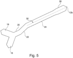
- the securement device 10 may be perforated along the longitudinal axis 100.
- the perforation of the securement device 10 may extend along the longitudinal axis from the second end 12b.
- the perforation may extend along the length of the second anchor portion 26.
- the perforation may also extend at least partially into the third bridge portion 24.
- the perforation of the securement device 10 extends along the second anchor portion 26 and the third bridge portion 24, and is illustrated by a dashed line 30 which lies on the longitudinal axis (not shown).
- the perforation of the securement device 10 enables the second anchor portion 26 to be separated into two strips.
- the separation of the second anchor portion 26 may advantageously improve the fixation of the securement device 10 to a patient for certain positions of the oral or nasal device.
- the adhesive may be provided on the back side of the strip 12 and may be initially covered with a removable cover material. When the securement device 10 is to be used, the cover material may be removed to expose the adhesive and the adhesive may subsequently be used to affix the strip 12 to the oral or nasal device, and the strip 12 to the face of the patient 200.
- the adhesive may be provided over the entire surface of the back side of the strip 12 or the adhesive may be provided on one or more selected regions of the back side of the strip 12.
- the adhesive is preferably one that provides an adequate securement of the strip 12 to the patient and/or the oral or nasal device but is not so strong that the skin of the patient is significantly damaged when the strip 12 is removed therefrom. Ideally, the adhesive strikes a balance between providing security of fitting whilst minimizing skin damage.
- multiple adhesives or an adhesive having varying strengths may be provided on the strip 12.
- a different adhesive may be provided for securing the strip 12 to the oral or nasal device relative to the adhesive provided for affixing the strip 12 to the face of the patient 200.
- the securement device 10 may comprise any suitable material.
- a suitable material for the securement device 10 consideration may be given to: the integrity of the material (i.e. signs of peeling, wrinkling or moisture absorption of the material during use); the ease of removal from a patient; and the kindness of the material to the patient's skin (i.e. whether the tape causes redness, soreness, irritation, abrasions or tearing of the skin).
- An example of a suitable material for the securement device 10 is a medical tape.
- a preferred example of a suitable medical tape for the securement device 10 is 3M TM Microfoam Surgical Tape 1528.
- 3M TM Microfoam Surgical Tape 1528 performs better than other examples of medical tapes with regard to material integrity, ease of removal and kindness to skin.
- the tape comprises a poly(vinyl chloride) foam layer with an acrylate adhesive.
- An alternative example of a suitable medical tape is the 3M TM Medical White Rayon Nonwoven Tape 1530 which comprises a non-woven rayon tape with a pressure sensitive, hypoallergenic acrylate adhesive.
- Another example of a suitable medical tape is the 3M TM Single Coated Polyilefin Medical Tape 1527 which comprises a perforated polyolefin tape coated with a pressure sensitive, hypoallergenic acrylate adhesive.
- the securement device 10 may be sterile and be provided in a sterile package that may be opened when required to provide the sterile securement device 10.
- the securement device 10 may be intended for a single use and may be disposed after a single use.
- Embodiments of the present invention may improve patient safety by reducing rates of infection and/or accidental extubation. Additionally or alternatively, patient experience may be improved by reducing the likelihood and severity of skin tears on the face (e.g. the lips). As such, the length of stay in hospital may be reduced for patients and costs associated with hospital acquired infections (HAls) may be reduced.
- Hls hospital acquired infections
- Embodiments of the present invention may be less costly in comparison to prior art securement devices which include multiple materials and/or moulded parts. Additionally, embodiments of the present invention may provide improved versatility relative to prior art devices, since the present invention is not necessarily limited to use with oral or nasal devices of any particular diameter. Securement devices 10 according to embodiments of the present invention may be more secure and less damaging to the skin relative to standard medical tape. Furthermore, securement devices 10 according to embodiments of the present invention may reduce infection risk relative to a roll of tape which may be used on multiple patients. Indeed, the use of a securement device 10 in accordance with embodiments of the present invention may help to introduce new best practice in hospitals given its suitability to single usage.
Landscapes
- Health & Medical Sciences (AREA)
- Pulmonology (AREA)
- Life Sciences & Earth Sciences (AREA)
- Hematology (AREA)
- Animal Behavior & Ethology (AREA)
- Anesthesiology (AREA)
- Biomedical Technology (AREA)
- Heart & Thoracic Surgery (AREA)
- Veterinary Medicine (AREA)
- Public Health (AREA)
- Engineering & Computer Science (AREA)
- General Health & Medical Sciences (AREA)
- Emergency Medicine (AREA)
- Otolaryngology (AREA)
- Biophysics (AREA)
- Orthopedics, Nursing, And Contraception (AREA)
- Media Introduction/Drainage Providing Device (AREA)
Claims (15)
- Befestigungsvorrichtung (10) für eine vorstehende Mund- oder Nasenvorrichtung (300), die einen durchgehenden Streifen (12) umfasst, der sich entlang einer Längsachse (100) zwischen einem ersten Ende (12a) und einem zweiten Ende (12b) erstreckt, wobei der durchgehende Streifen aufweist:einen ersten Ankerabschnitt (14) am ersten Ende;einen zweiten Ankerabschnitt (26) am zweiten Ende;einen ersten Brückenabschnitt (20);einen zweiten Brückenabschnitt (22); undeinen Klebstoff zum Anheften des Streifens an einem Patienten (200);wobei der erste Brückenabschnitt (20) zwischen dem ersten Ankerabschnitt (14) und dem zweiten Brückenabschnitt (22) angeordnet ist, der zweite Brückenabschnitt (22) zwischen dem ersten Brückenabschnitt (20) und dem zweiten Ankerabschnitt (26) angeordnet ist, sich der zweite Brückenabschnitt (22) in einem Winkel relativ zur Längsachse (100) erstreckt und der erste Ankerabschnitt (14) und der zweite Ankerabschnitt (26) relativ zur Längsachse (100) gegeneinander versetzt sind.
- Befestigungsvorrichtung (10) nach Anspruch 1, wobei der erste Brückenabschnitt (20) im Wesentlichen mit der Längsachse (100) ausgerichtet ist.
- Befestigungsvorrichtung (10) nach Anspruch 1 oder 2, umfassend einen dritten Brückenabschnitt (24), der zwischen dem zweiten Brückenabschnitt (22) und dem zweiten Ankerabschnitt (26) angeordnet ist, und optional wobei der dritte Brückenabschnitt (24) im Wesentlichen mit der Längsachse (100) ausgerichtet ist.
- Befestigungsvorrichtung (10) nach einem der vorhergehenden Ansprüche, wobei der erste Ankerabschnitt (14) und/oder der zweite Ankerabschnitt (26) eine Vielzahl von Gliedern (16, 18) beinhalten und optional wobei die Vielzahl von Gliedern (16, 18) ein Paar von Gliedern umfasst, die sich voneinander erstrecken.
- Befestigungsvorrichtung (10) nach Anspruch 4, wobei die Vielzahl von Gliedern (16, 18) das Paar von Gliedern umfasst, die sich voneinander erstrecken, und wobei das Paar von Gliedern (16, 18) eine V-Form bildet, und optional wobei das Paar von Gliedern (16, 18) einen Schnittwinkel zwischen 70° und 110° bildet.
- Befestigungsvorrichtung (10) nach einem der vorhergehenden Ansprüche, wobei der Streifen (12) entlang der Längsachse (100) eine Länge zwischen 15 cm und 45 cm, und optional von etwa 30 cm aufweist und/oder wobei sich der erste Brückenabschnitt (20) über eine Länge zwischen 1 cm und 4 cm und optional von etwa 2 cm erstreckt.
- Befestigungsvorrichtung (10) nach einem der vorhergehenden Ansprüche, wobei sich der zweite Brückenabschnitt (22) über eine Länge zwischen 1 cm und 4 cm, und optional von etwa 2 cm erstreckt und/oder wobei sich der zweite Brückenabschnitt (22) in einem Winkel zwischen 10° und 80° und optional von etwa 45° relativ zur Längsachse (100) erstreckt.
- Befestigungsvorrichtung (10) nach einem der vorhergehenden Ansprüche, wobei der Klebstoff auf einer Rückseite des Streifens (12) vorgesehen ist und optional wobei der Klebstoff in ausgewählten Bereichen der Rückseite des Streifens (12) vorgesehen ist oder der Klebstoff im Wesentlichen über der gesamten Rückseite des Streifens (12) vorgesehen ist.
- Befestigungsvorrichtung (10) nach einem der vorhergehenden Ansprüche, umfassend eine Perforation (30) entlang des zweiten Ankerabschnitts (26).
- Befestigungsvorrichtung (10) nach Anspruch 9, wobei sich die Perforation (30) vom zweiten Ende (12b) entlang der Längsachse (100) erstreckt und/oder wobei sich die Perforation (30) in den Brückenabschnitt neben dem zweiten Ankerabschnitt (26) erstreckt.
- Kit, umfassend eine Verpackung, die eine Befestigungsvorrichtung (10) nach einem der vorhergehenden Ansprüche enthält, und optional wobei sich die Befestigungsvorrichtung (10) in einem sterilen Zustand in der Verpackung vor dem Öffnen der Verpackung befindet.
- Anordnung, umfassend:eine Mund- oder Nasenvorrichtung (300);eine Befestigungsvorrichtung (10) nach einem der Ansprüche 1 bis 10; wobei die Befestigungsvorrichtung (10) um die Mund- oder Nasenvorrichtung (300) so gewickelt ist, dass sich der erste Ankerabschnitt (14) und der zweite Ankerabschnitt (26) von gegenüberliegenden Seiten der Mund- oder Nasenvorrichtung (300) erstrecken, und optionalwobei der zweite Brückenabschnitt (22) der Befestigungsvorrichtung (10) um die Mund- oder Nasenvorrichtung (300) gewickelt ist.
- Verfahren zum Anbringen einer Befestigungsvorrichtung (10) an einer vorstehenden Mund- oder Nasenvorrichtung (300) und einem Patienten, umfassend:Bereitstellen einer Mund- oder Nasenvorrichtung (300), die aus einem Patienten (200) vorsteht;Bereitstellen einer Befestigungsvorrichtung (10) nach einem der Ansprüche 1 bis 10; Wickeln der Befestigungsvorrichtung (10) um die aus einem Patienten (200) vorstehende Mund- und Nasenvorrichtung (300) und Ankleben des ersten Ankerabschnitts (14) und des zweiten Ankerabschnitts (26) an dem Patienten (200) auf gegenüberliegenden Seiten der Mund- oder Nasenvorrichtung (300).
- Verfahren nach Anspruch 13, wobei das Wickeln der Befestigungsvorrichtung (10) um das Rohr (300) das Wickeln des zweiten Brückenabschnitts (22) um die Mund- oder Nasenvorrichtung (300) umfasst und/oder wobei die Befestigungsvorrichtung (10) um die Mund- oder Nasenvorrichtung (300) gewickelt wird und der erste Ankerabschnitt (14) so am Patienten (200) angeklebt wird, dass der erste Brückenabschnitt (20) von dem ersten Ankerabschnitt (14) weg in Richtung der Lippen (202) des Patienten (200) führt.
- Verfahren nach einem der Ansprüche 13 bis 14, wenn abhängig von einem der Ansprüche 4 bis 5, wobei ein erstes Glied (16) der Vielzahl von Gliedern (16, 18) im Bereich des Wangenknochens des Patienten (200) angeklebt wird und ein zweites Glied (18) der Vielzahl von Gliedern (16, 18) im Bereich des Kieferknochens des Patienten (200) angeklebt wird.
Applications Claiming Priority (2)
| Application Number | Priority Date | Filing Date | Title |
|---|---|---|---|
| GBGB1819185.8A GB201819185D0 (en) | 2018-11-26 | 2018-11-26 | Securement device for an endotracheal tube |
| PCT/GB2019/053336 WO2020109775A1 (en) | 2018-11-26 | 2019-11-26 | Securement device for a protruding oral or nasal device |
Publications (3)
| Publication Number | Publication Date |
|---|---|
| EP3886965A1 EP3886965A1 (de) | 2021-10-06 |
| EP3886965B1 true EP3886965B1 (de) | 2024-12-04 |
| EP3886965C0 EP3886965C0 (de) | 2024-12-04 |
Family
ID=65024490
Family Applications (1)
| Application Number | Title | Priority Date | Filing Date |
|---|---|---|---|
| EP19816403.0A Active EP3886965B1 (de) | 2018-11-26 | 2019-11-26 | Befestigungsvorrichtung für eine vorstehende mund- oder nasenvorrichtung |
Country Status (6)
| Country | Link |
|---|---|
| US (1) | US12115312B2 (de) |
| EP (1) | EP3886965B1 (de) |
| CN (2) | CN113164714B (de) |
| ES (1) | ES2998392T3 (de) |
| GB (1) | GB201819185D0 (de) |
| WO (1) | WO2020109775A1 (de) |
Families Citing this family (2)
| Publication number | Priority date | Publication date | Assignee | Title |
|---|---|---|---|---|
| EP3938022A1 (de) * | 2019-03-13 | 2022-01-19 | 3M Innovative Properties Company | Rohrbefestigungsvorrichtung |
| US12036367B2 (en) * | 2020-06-05 | 2024-07-16 | Kelcor, Llc | Airway and eye taping system and method of its use |
Family Cites Families (27)
| Publication number | Priority date | Publication date | Assignee | Title |
|---|---|---|---|---|
| US5308339A (en) * | 1985-05-03 | 1994-05-03 | Medical Distributors, Inc. | Universal clamp |
| US5300037A (en) * | 1993-01-13 | 1994-04-05 | Ansley Medical Products, Inc. | Medical conduit holder |
| DK9400004U3 (da) * | 1994-01-06 | 1994-02-25 | Nikomed Aps | Specielt udviklet plaster til fixering af orale, endo-tracheale anæstesi-tuber |
| US5546938A (en) | 1995-08-24 | 1996-08-20 | Mckenzie; Shirley T. | ICU patients ventilator tube holding device |
| WO1998010823A1 (en) * | 1996-09-10 | 1998-03-19 | Nikomed Aps | A bandage for fixating a cannula of a venous catheter to a skin surface part of a person |
| US5735272A (en) * | 1997-01-22 | 1998-04-07 | Dillon; Michael M. | Nasal tube holder having a nasal dilator attached thereto |
| US5797394A (en) * | 1997-02-04 | 1998-08-25 | Avail Medical Products, Inc. | Tracheal tube securing strap |
| US20050171482A1 (en) * | 2003-09-08 | 2005-08-04 | Russo Ronald D. | Medical tube holder with angled tabs |
| US8230862B2 (en) | 2009-02-10 | 2012-07-31 | Mcinnes John Gordon | Tracheal tube support apparatus |
| US8794240B1 (en) * | 2010-02-16 | 2014-08-05 | Majorus Medical, Inc. | Apparatus for securing a tracheal tube or the like to a patient |
| CN203029790U (zh) | 2012-12-31 | 2013-07-03 | 青岛木易科贸有限公司 | 一种用于鼻管固定的鼻贴 |
| CN203139349U (zh) | 2013-03-22 | 2013-08-21 | 武汉大学 | 一种固定胃管的保护套管 |
| DE102013012365B4 (de) | 2013-07-25 | 2019-06-13 | Fresenius Medical Care Deutschland Gmbh | Sterile Schlauchabdeckung für ein medizinisches Schlauchleitungssystem |
| CN203507284U (zh) | 2013-08-30 | 2014-04-02 | 中国人民解放军总医院 | 一种胃管固定装置 |
| CN203694318U (zh) | 2014-01-13 | 2014-07-09 | 常州市儿童医院 | 一种h型气管导管的固定胶布 |
| CN203694352U (zh) | 2014-01-26 | 2014-07-09 | 常州市儿童医院 | 一种导管的x型固定胶布 |
| CN203694353U (zh) | 2014-01-26 | 2014-07-09 | 常州市儿童医院 | 一种导管的t型固定胶布 |
| WO2015187995A2 (en) * | 2014-06-04 | 2015-12-10 | Revolutionary Medical Devices, Inc. | Combined nasal and mouth ventilation mask |
| ES3059021T3 (en) * | 2014-09-19 | 2026-03-16 | Fisher & Paykel Healthcare Ltd | Patient interface |
| TWM498596U (zh) | 2014-12-18 | 2015-04-11 | Jie-Fu Chen | 鼻胃管固定貼之結構 |
| CN204766966U (zh) | 2015-06-30 | 2015-11-18 | 中国人民解放军第四军医大学 | 一种用于固定经鼻气管插管的鼻贴 |
| EP3337546B1 (de) | 2015-08-21 | 2020-09-23 | 3M Innovative Properties Company | Systeme zur sicherung eines transnasalen magenbandes |
| EP3337548B1 (de) * | 2015-08-21 | 2021-09-29 | 3M Innovative Properties Company | Systeme zur sicherung eines transnasalen magenbandes |
| CN105879180B (zh) | 2016-05-24 | 2019-04-05 | 刘义 | 一种经鼻插管导管固定器 |
| TWM531845U (zh) | 2016-06-08 | 2016-11-11 | Univ Chang Gung Science & Technology | 鼻胃管固定貼片 |
| CN106823104A (zh) | 2017-02-27 | 2017-06-13 | 徐辉 | 一种胃管固定贴、固定方法及其拉力实验方法 |
| CN208114906U (zh) | 2017-04-19 | 2018-11-20 | 无锡康特佳健康科技有限公司 | 一种插管固定贴 |
-
2018
- 2018-11-26 GB GBGB1819185.8A patent/GB201819185D0/en not_active Ceased
-
2019
- 2019-11-26 EP EP19816403.0A patent/EP3886965B1/de active Active
- 2019-11-26 CN CN201980077651.1A patent/CN113164714B/zh active Active
- 2019-11-26 CN CN202410188553.8A patent/CN118022140A/zh active Pending
- 2019-11-26 US US17/296,273 patent/US12115312B2/en active Active
- 2019-11-26 ES ES19816403T patent/ES2998392T3/es active Active
- 2019-11-26 WO PCT/GB2019/053336 patent/WO2020109775A1/en not_active Ceased
Also Published As
| Publication number | Publication date |
|---|---|
| US12115312B2 (en) | 2024-10-15 |
| WO2020109775A1 (en) | 2020-06-04 |
| EP3886965A1 (de) | 2021-10-06 |
| US20220339384A1 (en) | 2022-10-27 |
| ES2998392T3 (en) | 2025-02-20 |
| ES2998392T8 (es) | 2025-03-04 |
| CN113164714B (zh) | 2024-03-08 |
| CN113164714A (zh) | 2021-07-23 |
| CN118022140A (zh) | 2024-05-14 |
| GB201819185D0 (en) | 2019-01-09 |
| EP3886965C0 (de) | 2024-12-04 |
Similar Documents
| Publication | Publication Date | Title |
|---|---|---|
| US6561192B2 (en) | Nasal oral respiratory interface | |
| US6551285B1 (en) | Medical line securement device for use with neonates | |
| US20080140044A1 (en) | Infant CPAP nasal cannula seal | |
| US5341802A (en) | Endotracheal tube stabilizing device | |
| US20020143296A1 (en) | Medical tube holder | |
| EP3886965B1 (de) | Befestigungsvorrichtung für eine vorstehende mund- oder nasenvorrichtung | |
| US20090211573A1 (en) | Endotracheal tube holder with improved locking device | |
| HK40053285A (en) | Securement device for a protruding oral or nasal device | |
| HK40053285B (en) | Securement device for a protruding oral or nasal device | |
| US12036367B2 (en) | Airway and eye taping system and method of its use | |
| HK40111434A (zh) | 用於突出的口部或鼻部装置的固定装置 | |
| US20170173287A1 (en) | Endotracheal tube securing device and method | |
| CN222853836U (zh) | 一种胃镜检查用改良牙垫 | |
| EP1047469A1 (de) | Vorrichtung zum befestigen eines schlauchelementes | |
| CN110975100B (zh) | 气管切开后插管固定装置 | |
| US20240066245A1 (en) | Device for Collecting Seepage from a Tracheal Incision | |
| CN211724168U (zh) | 一种医用痰液遮挡器 | |
| CN217391350U (zh) | 一种气管插管固定套 | |
| CN213491386U (zh) | 一种经鼻气管插管固定装置 | |
| CN222383526U (zh) | 一种睡眠监测用管线固定小胶贴 | |
| CN222056109U (zh) | 气管插管固定装置 | |
| CN217886729U (zh) | 一种经鼻气管导管用固定装置 | |
| EP4140526B1 (de) | Narkosegasspülungs- und sanitäre beatmungsschlauchbefestigungsvorrichtung | |
| CN211272979U (zh) | 一种工字型经口气管插管固定贴组 | |
| CN104043175B (zh) | 一种口鼻插管固定器 |
Legal Events
| Date | Code | Title | Description |
|---|---|---|---|
| STAA | Information on the status of an ep patent application or granted ep patent |
Free format text: STATUS: UNKNOWN |
|
| STAA | Information on the status of an ep patent application or granted ep patent |
Free format text: STATUS: THE INTERNATIONAL PUBLICATION HAS BEEN MADE |
|
| PUAI | Public reference made under article 153(3) epc to a published international application that has entered the european phase |
Free format text: ORIGINAL CODE: 0009012 |
|
| STAA | Information on the status of an ep patent application or granted ep patent |
Free format text: STATUS: REQUEST FOR EXAMINATION WAS MADE |
|
| 17P | Request for examination filed |
Effective date: 20210512 |
|
| AK | Designated contracting states |
Kind code of ref document: A1 Designated state(s): AL AT BE BG CH CY CZ DE DK EE ES FI FR GB GR HR HU IE IS IT LI LT LU LV MC MK MT NL NO PL PT RO RS SE SI SK SM TR |
|
| REG | Reference to a national code |
Ref country code: HK Ref legal event code: DE Ref document number: 40053285 Country of ref document: HK |
|
| DAV | Request for validation of the european patent (deleted) | ||
| DAX | Request for extension of the european patent (deleted) | ||
| GRAP | Despatch of communication of intention to grant a patent |
Free format text: ORIGINAL CODE: EPIDOSNIGR1 |
|
| STAA | Information on the status of an ep patent application or granted ep patent |
Free format text: STATUS: GRANT OF PATENT IS INTENDED |
|
| INTG | Intention to grant announced |
Effective date: 20240117 |
|
| GRAJ | Information related to disapproval of communication of intention to grant by the applicant or resumption of examination proceedings by the epo deleted |
Free format text: ORIGINAL CODE: EPIDOSDIGR1 |
|
| STAA | Information on the status of an ep patent application or granted ep patent |
Free format text: STATUS: REQUEST FOR EXAMINATION WAS MADE |
|
| INTC | Intention to grant announced (deleted) | ||
| RIN1 | Information on inventor provided before grant (corrected) |
Inventor name: BROTHWOOD, ROBERT Inventor name: CULLINANE, MATTHEW JOHN |
|
| GRAP | Despatch of communication of intention to grant a patent |
Free format text: ORIGINAL CODE: EPIDOSNIGR1 |
|
| STAA | Information on the status of an ep patent application or granted ep patent |
Free format text: STATUS: GRANT OF PATENT IS INTENDED |
|
| INTG | Intention to grant announced |
Effective date: 20240704 |
|
| RAP3 | Party data changed (applicant data changed or rights of an application transferred) |
Owner name: LIVERPOOL UNIVERSITY HOSPITALS NHS FOUNDATIONTRUST |
|
| GRAS | Grant fee paid |
Free format text: ORIGINAL CODE: EPIDOSNIGR3 |
|
| GRAA | (expected) grant |
Free format text: ORIGINAL CODE: 0009210 |
|
| STAA | Information on the status of an ep patent application or granted ep patent |
Free format text: STATUS: THE PATENT HAS BEEN GRANTED |
|
| AK | Designated contracting states |
Kind code of ref document: B1 Designated state(s): AL AT BE BG CH CY CZ DE DK EE ES FI FR GB GR HR HU IE IS IT LI LT LU LV MC MK MT NL NO PL PT RO RS SE SI SK SM TR |
|
| REG | Reference to a national code |
Ref country code: CH Ref legal event code: EP |
|
| REG | Reference to a national code |
Ref country code: DE Ref legal event code: R096 Ref document number: 602019063074 Country of ref document: DE |
|
| REG | Reference to a national code |
Ref country code: IE Ref legal event code: FG4D |
|
| U01 | Request for unitary effect filed |
Effective date: 20241210 |
|
| U07 | Unitary effect registered |
Designated state(s): AT BE BG DE DK EE FI FR IT LT LU LV MT NL PT RO SE SI Effective date: 20241220 |
|
| REG | Reference to a national code |
Ref country code: ES Ref legal event code: FG2A Ref document number: 2998392 Country of ref document: ES Kind code of ref document: T3 Effective date: 20250220 |
|
| PG25 | Lapsed in a contracting state [announced via postgrant information from national office to epo] |
Ref country code: HR Free format text: LAPSE BECAUSE OF FAILURE TO SUBMIT A TRANSLATION OF THE DESCRIPTION OR TO PAY THE FEE WITHIN THE PRESCRIBED TIME-LIMIT Effective date: 20241204 |
|
| PG25 | Lapsed in a contracting state [announced via postgrant information from national office to epo] |
Ref country code: NO Free format text: LAPSE BECAUSE OF FAILURE TO SUBMIT A TRANSLATION OF THE DESCRIPTION OR TO PAY THE FEE WITHIN THE PRESCRIBED TIME-LIMIT Effective date: 20250304 |
|
| PG25 | Lapsed in a contracting state [announced via postgrant information from national office to epo] |
Ref country code: RS Free format text: LAPSE BECAUSE OF FAILURE TO SUBMIT A TRANSLATION OF THE DESCRIPTION OR TO PAY THE FEE WITHIN THE PRESCRIBED TIME-LIMIT Effective date: 20250304 |
|
| REG | Reference to a national code |
Ref country code: GR Ref legal event code: EP Ref document number: 20250400466 Country of ref document: GR Effective date: 20250409 |
|
| PG25 | Lapsed in a contracting state [announced via postgrant information from national office to epo] |
Ref country code: SM Free format text: LAPSE BECAUSE OF FAILURE TO SUBMIT A TRANSLATION OF THE DESCRIPTION OR TO PAY THE FEE WITHIN THE PRESCRIBED TIME-LIMIT Effective date: 20241204 |
|
| PG25 | Lapsed in a contracting state [announced via postgrant information from national office to epo] |
Ref country code: PL Free format text: LAPSE BECAUSE OF FAILURE TO SUBMIT A TRANSLATION OF THE DESCRIPTION OR TO PAY THE FEE WITHIN THE PRESCRIBED TIME-LIMIT Effective date: 20241204 |
|
| PG25 | Lapsed in a contracting state [announced via postgrant information from national office to epo] |
Ref country code: IS Free format text: LAPSE BECAUSE OF FAILURE TO SUBMIT A TRANSLATION OF THE DESCRIPTION OR TO PAY THE FEE WITHIN THE PRESCRIBED TIME-LIMIT Effective date: 20250404 |
|
| PG25 | Lapsed in a contracting state [announced via postgrant information from national office to epo] |
Ref country code: SK Free format text: LAPSE BECAUSE OF FAILURE TO SUBMIT A TRANSLATION OF THE DESCRIPTION OR TO PAY THE FEE WITHIN THE PRESCRIBED TIME-LIMIT Effective date: 20241204 |
|
| PG25 | Lapsed in a contracting state [announced via postgrant information from national office to epo] |
Ref country code: CZ Free format text: LAPSE BECAUSE OF FAILURE TO SUBMIT A TRANSLATION OF THE DESCRIPTION OR TO PAY THE FEE WITHIN THE PRESCRIBED TIME-LIMIT Effective date: 20241204 |
|
| PLBE | No opposition filed within time limit |
Free format text: ORIGINAL CODE: 0009261 |
|
| STAA | Information on the status of an ep patent application or granted ep patent |
Free format text: STATUS: NO OPPOSITION FILED WITHIN TIME LIMIT |
|
| 26N | No opposition filed |
Effective date: 20250905 |
|
| U20 | Renewal fee for the european patent with unitary effect paid |
Year of fee payment: 7 Effective date: 20251030 |
|
| PGFP | Annual fee paid to national office [announced via postgrant information from national office to epo] |
Ref country code: GB Payment date: 20251106 Year of fee payment: 7 |
|
| PGFP | Annual fee paid to national office [announced via postgrant information from national office to epo] |
Ref country code: TR Payment date: 20251112 Year of fee payment: 7 Ref country code: GR Payment date: 20251112 Year of fee payment: 7 |
|
| PGFP | Annual fee paid to national office [announced via postgrant information from national office to epo] |
Ref country code: ES Payment date: 20251202 Year of fee payment: 7 |