EP3886271B1 - Leckageschutzvorrichtung - Google Patents
Leckageschutzvorrichtung Download PDFInfo
- Publication number
- EP3886271B1 EP3886271B1 EP20172918.3A EP20172918A EP3886271B1 EP 3886271 B1 EP3886271 B1 EP 3886271B1 EP 20172918 A EP20172918 A EP 20172918A EP 3886271 B1 EP3886271 B1 EP 3886271B1
- Authority
- EP
- European Patent Office
- Prior art keywords
- assembly
- housing
- leakage protection
- protection device
- output
- Prior art date
- Legal status (The legal status is an assumption and is not a legal conclusion. Google has not performed a legal analysis and makes no representation as to the accuracy of the status listed.)
- Active
Links
Images


Classifications
-
- H—ELECTRICITY
- H01—ELECTRIC ELEMENTS
- H01H—ELECTRIC SWITCHES; RELAYS; SELECTORS; EMERGENCY PROTECTIVE DEVICES
- H01H83/00—Protective switches, e.g. circuit-breaking switches, or protective relays operated by abnormal electrical conditions otherwise than solely by excess current
- H01H83/02—Protective switches, e.g. circuit-breaking switches, or protective relays operated by abnormal electrical conditions otherwise than solely by excess current operated by earth fault currents
- H01H83/04—Protective switches, e.g. circuit-breaking switches, or protective relays operated by abnormal electrical conditions otherwise than solely by excess current operated by earth fault currents with testing means for indicating the ability of the switch or relay to function properly
-
- H—ELECTRICITY
- H01—ELECTRIC ELEMENTS
- H01R—ELECTRICALLY-CONDUCTIVE CONNECTIONS; STRUCTURAL ASSOCIATIONS OF A PLURALITY OF MUTUALLY-INSULATED ELECTRICAL CONNECTING ELEMENTS; COUPLING DEVICES; CURRENT COLLECTORS
- H01R13/00—Details of coupling devices of the kinds covered by groups H01R12/70 or H01R24/00 - H01R33/00
- H01R13/02—Contact members
- H01R13/04—Pins or blades for co-operation with sockets
-
- H—ELECTRICITY
- H01—ELECTRIC ELEMENTS
- H01R—ELECTRICALLY-CONDUCTIVE CONNECTIONS; STRUCTURAL ASSOCIATIONS OF A PLURALITY OF MUTUALLY-INSULATED ELECTRICAL CONNECTING ELEMENTS; COUPLING DEVICES; CURRENT COLLECTORS
- H01R13/00—Details of coupling devices of the kinds covered by groups H01R12/70 or H01R24/00 - H01R33/00
- H01R13/46—Bases; Cases
- H01R13/502—Bases; Cases composed of different pieces
-
- H—ELECTRICITY
- H01—ELECTRIC ELEMENTS
- H01R—ELECTRICALLY-CONDUCTIVE CONNECTIONS; STRUCTURAL ASSOCIATIONS OF A PLURALITY OF MUTUALLY-INSULATED ELECTRICAL CONNECTING ELEMENTS; COUPLING DEVICES; CURRENT COLLECTORS
- H01R13/00—Details of coupling devices of the kinds covered by groups H01R12/70 or H01R24/00 - H01R33/00
- H01R13/46—Bases; Cases
- H01R13/52—Dustproof, splashproof, drip-proof, waterproof, or flameproof cases
-
- H—ELECTRICITY
- H01—ELECTRIC ELEMENTS
- H01R—ELECTRICALLY-CONDUCTIVE CONNECTIONS; STRUCTURAL ASSOCIATIONS OF A PLURALITY OF MUTUALLY-INSULATED ELECTRICAL CONNECTING ELEMENTS; COUPLING DEVICES; CURRENT COLLECTORS
- H01R13/00—Details of coupling devices of the kinds covered by groups H01R12/70 or H01R24/00 - H01R33/00
- H01R13/66—Structural association with built-in electrical component
- H01R13/665—Structural association with built-in electrical component with built-in electronic circuit
- H01R13/6691—Structural association with built-in electrical component with built-in electronic circuit with built-in signalling means
-
- H—ELECTRICITY
- H01—ELECTRIC ELEMENTS
- H01R—ELECTRICALLY-CONDUCTIVE CONNECTIONS; STRUCTURAL ASSOCIATIONS OF A PLURALITY OF MUTUALLY-INSULATED ELECTRICAL CONNECTING ELEMENTS; COUPLING DEVICES; CURRENT COLLECTORS
- H01R13/00—Details of coupling devices of the kinds covered by groups H01R12/70 or H01R24/00 - H01R33/00
- H01R13/66—Structural association with built-in electrical component
- H01R13/70—Structural association with built-in electrical component with built-in switch
- H01R13/703—Structural association with built-in electrical component with built-in switch operated by engagement or disengagement of coupling parts, e.g. dual-continuity coupling part
- H01R13/7031—Shorting, shunting or bussing of different terminals interrupted or effected on engagement of coupling part, e.g. for ESD protection, line continuity
-
- H—ELECTRICITY
- H01—ELECTRIC ELEMENTS
- H01R—ELECTRICALLY-CONDUCTIVE CONNECTIONS; STRUCTURAL ASSOCIATIONS OF A PLURALITY OF MUTUALLY-INSULATED ELECTRICAL CONNECTING ELEMENTS; COUPLING DEVICES; CURRENT COLLECTORS
- H01R13/00—Details of coupling devices of the kinds covered by groups H01R12/70 or H01R24/00 - H01R33/00
- H01R13/66—Structural association with built-in electrical component
- H01R13/70—Structural association with built-in electrical component with built-in switch
- H01R13/713—Structural association with built-in electrical component with built-in switch the switch being a safety switch
- H01R13/7135—Structural association with built-in electrical component with built-in switch the switch being a safety switch with ground fault protector
-
- H—ELECTRICITY
- H01—ELECTRIC ELEMENTS
- H01R—ELECTRICALLY-CONDUCTIVE CONNECTIONS; STRUCTURAL ASSOCIATIONS OF A PLURALITY OF MUTUALLY-INSULATED ELECTRICAL CONNECTING ELEMENTS; COUPLING DEVICES; CURRENT COLLECTORS
- H01R24/00—Two-part coupling devices, or either of their cooperating parts, characterised by their overall structure
- H01R24/28—Coupling parts carrying pins, blades or analogous contacts and secured only to wire or cable
- H01R24/30—Coupling parts carrying pins, blades or analogous contacts and secured only to wire or cable with additional earth or shield contacts
-
- H—ELECTRICITY
- H02—GENERATION; CONVERSION OR DISTRIBUTION OF ELECTRIC POWER
- H02H—EMERGENCY PROTECTIVE CIRCUIT ARRANGEMENTS
- H02H3/00—Emergency protective circuit arrangements for automatic disconnection directly responsive to an undesired change from normal electric working condition with or without subsequent reconnection ; integrated protection
- H02H3/02—Details
- H02H3/04—Details with warning or supervision in addition to disconnection, e.g. for indicating that protective apparatus has functioned
-
- H—ELECTRICITY
- H02—GENERATION; CONVERSION OR DISTRIBUTION OF ELECTRIC POWER
- H02H—EMERGENCY PROTECTIVE CIRCUIT ARRANGEMENTS
- H02H3/00—Emergency protective circuit arrangements for automatic disconnection directly responsive to an undesired change from normal electric working condition with or without subsequent reconnection ; integrated protection
- H02H3/26—Emergency protective circuit arrangements for automatic disconnection directly responsive to an undesired change from normal electric working condition with or without subsequent reconnection ; integrated protection responsive to difference between voltages or between currents; responsive to phase angle between voltages or between currents
- H02H3/32—Emergency protective circuit arrangements for automatic disconnection directly responsive to an undesired change from normal electric working condition with or without subsequent reconnection ; integrated protection responsive to difference between voltages or between currents; responsive to phase angle between voltages or between currents involving comparison of the voltage or current values at corresponding points in different conductors of a single system, e.g. of currents in go and return conductors
-
- H—ELECTRICITY
- H01—ELECTRIC ELEMENTS
- H01R—ELECTRICALLY-CONDUCTIVE CONNECTIONS; STRUCTURAL ASSOCIATIONS OF A PLURALITY OF MUTUALLY-INSULATED ELECTRICAL CONNECTING ELEMENTS; COUPLING DEVICES; CURRENT COLLECTORS
- H01R12/00—Structural associations of a plurality of mutually-insulated electrical connecting elements, specially adapted for printed circuits, e.g. printed circuit boards [PCB], flat or ribbon cables, or like generally planar structures, e.g. terminal strips, terminal blocks; Coupling devices specially adapted for printed circuits, flat or ribbon cables, or like generally planar structures; Terminals specially adapted for contact with, or insertion into, printed circuits, flat or ribbon cables, or like generally planar structures
- H01R12/70—Coupling devices
- H01R12/71—Coupling devices for rigid printing circuits or like structures
- H01R12/712—Coupling devices for rigid printing circuits or like structures co-operating with the surface of the printed circuit or with a coupling device exclusively provided on the surface of the printed circuit
- H01R12/714—Coupling devices for rigid printing circuits or like structures co-operating with the surface of the printed circuit or with a coupling device exclusively provided on the surface of the printed circuit with contacts abutting directly the printed circuit; Button contacts therefore provided on the printed circuit
-
- H—ELECTRICITY
- H01—ELECTRIC ELEMENTS
- H01R—ELECTRICALLY-CONDUCTIVE CONNECTIONS; STRUCTURAL ASSOCIATIONS OF A PLURALITY OF MUTUALLY-INSULATED ELECTRICAL CONNECTING ELEMENTS; COUPLING DEVICES; CURRENT COLLECTORS
- H01R13/00—Details of coupling devices of the kinds covered by groups H01R12/70 or H01R24/00 - H01R33/00
- H01R13/46—Bases; Cases
- H01R13/52—Dustproof, splashproof, drip-proof, waterproof, or flameproof cases
- H01R13/5205—Sealing means between cable and housing, e.g. grommet
-
- H—ELECTRICITY
- H02—GENERATION; CONVERSION OR DISTRIBUTION OF ELECTRIC POWER
- H02H—EMERGENCY PROTECTIVE CIRCUIT ARRANGEMENTS
- H02H3/00—Emergency protective circuit arrangements for automatic disconnection directly responsive to an undesired change from normal electric working condition with or without subsequent reconnection ; integrated protection
- H02H3/26—Emergency protective circuit arrangements for automatic disconnection directly responsive to an undesired change from normal electric working condition with or without subsequent reconnection ; integrated protection responsive to difference between voltages or between currents; responsive to phase angle between voltages or between currents
- H02H3/32—Emergency protective circuit arrangements for automatic disconnection directly responsive to an undesired change from normal electric working condition with or without subsequent reconnection ; integrated protection responsive to difference between voltages or between currents; responsive to phase angle between voltages or between currents involving comparison of the voltage or current values at corresponding points in different conductors of a single system, e.g. of currents in go and return conductors
- H02H3/33—Emergency protective circuit arrangements for automatic disconnection directly responsive to an undesired change from normal electric working condition with or without subsequent reconnection ; integrated protection responsive to difference between voltages or between currents; responsive to phase angle between voltages or between currents involving comparison of the voltage or current values at corresponding points in different conductors of a single system, e.g. of currents in go and return conductors using summation current transformers
- H02H3/334—Emergency protective circuit arrangements for automatic disconnection directly responsive to an undesired change from normal electric working condition with or without subsequent reconnection ; integrated protection responsive to difference between voltages or between currents; responsive to phase angle between voltages or between currents involving comparison of the voltage or current values at corresponding points in different conductors of a single system, e.g. of currents in go and return conductors using summation current transformers with means to produce an artificial imbalance for other protection or monitoring reasons or remote control
- H02H3/335—Emergency protective circuit arrangements for automatic disconnection directly responsive to an undesired change from normal electric working condition with or without subsequent reconnection ; integrated protection responsive to difference between voltages or between currents; responsive to phase angle between voltages or between currents involving comparison of the voltage or current values at corresponding points in different conductors of a single system, e.g. of currents in go and return conductors using summation current transformers with means to produce an artificial imbalance for other protection or monitoring reasons or remote control the main function being self testing of the device
Definitions
- the housing is configured to have a circular, square, rectangular or polygonal cross-sectional shape in a direction perpendicular to the first direction.
- Couple and “connect” should be understood broadly.
- connect can be a fixed connection, a detachable connection, or an integral connection
- Couple can be a direct connection or an indirect connection through an intermediate medium.
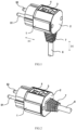
- Figs. 1 to 4 show leakage protection devices according to various alternative embodiments of the present disclosure.
- a plug is taken as an example, however, it should be understood that any other leakage protection devices applicable to the concept of the present disclosure is not excluded.
- the leakage protection device of the present disclosure includes a housing and a core assembly 8 disposed in the housing.
- the housing may include a housing base 1 and a housing cover 2 which are snap-fitted fixedly together by a plurality of fasteners or mechanical structures.
- the fasteners may be screws 21 and screw plugs 22 exemplarily shown in Figs. 5 and 6 .
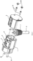
- the core assembly 8 includes a control circuit board, an input assembly and an output assembly which are coupled to the control circuit board, thereby realizing electrical connection between the input end and the output end.
- the input assembly includes plug blades 51, 52 extending out of the housing base 1 of the housing in a first direction D1
- the output assembly includes an output wiring device 6 extending out of the housing base 1 of the housing in a second direction.
- the second direction may be parallel to or angled with the first direction D1.
- the second direction is a direction D2 substantially perpendicular to the first direction D1
- the output assembly can further include a wire card 7 connected to the housing and extending out of the housing.
- the output wiring device 6 can realize electrical connection of the leakage protection device via the wire card 7, and has waterproof performance and improves bending resistance and service life of the output wiring device 6.
- the output wiring device 6 can include an output wire coupled to the core assembly or a wiring assembly connected to the output wire so that a user can freely connect the output wire.
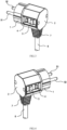
- the output wiring device 6 extends out of the housing cover 2 of the housing in the second direction, that is, the second direction in which the output wiring device 6 extends out of the housing may be parallel to the first direction D1, thereby enabling the leakage protection device to be suitable for more application environments.
- the leakage protection device includes a rest assembly (RESET) and a test assembly (TEST), wherein the reset assembly is used for controlling the core assembly to turn on the power supply and includes a reset button 3 arranged outside the housing, and the test assembly is used for simulating and testing leakage current and includes a test button 4 arranged outside the housing.
- the reset button 3 and the test button 4 are arranged on the outer peripheral surface of the housing parallel to the first direction D1 so that the operation directions or working directions of the reset button 3 and the test button 4 can be angled with the first direction D1, that is, angled with the extension direction of the plug blades 51, 52 of the input assembly.
- the operation directions of the reset button 3 and the test button 4 are configured to be perpendicular to the extension direction of the plug pieces 51, 52.
- the operation directions of the reset button 3 and the test button 4 are configured as along the direction D2. In this way, the internal structure of the leakage protection device can be designed to be more compact, and after the plug pieces 51, 52 being inserted into the mating socket, the external whole of the leakage protection device would not occupy too much space.
- the reset button 3 and the test button 4 can be arranged in parallel on the outer peripheral surface of the housing along the first direction D1, as shown in Figs. 1 and 2 .
- the reset button 3 and the test button 4 can also be arranged in parallel on the outer peripheral surface of the housing perpendicular to the first direction D1, that is, in parallel around the outer peripheral surface of the housing.
- the outer periphery of the housing can be configured as various forms.
- the housing is configured to have a circular, square, rectangular or polygonal cross-sectional shape in a direction perpendicular to the first direction D1.
- the polygonal cross-sectional shape is shown in the figures.
- the housing cover 2 is provided with an opening through which the reset button 3 and the test button 4 protrude.
- the distance that the reset button 3 and the test button 4 protrude out of the opening can be configured to not exceed the outer peripheral surface of the housing, thus making the overall appearance of the product more beautiful and the size more compact.
- the reset button 3 and the test button 4 are both configured as a substantially rectangular shape and have different sizes.
- the reset button 3 and the test button 4 can also be designed in any other suitable shapes or sizes.
- one or both of the two buttons may be circular, square or polygonal in shape, or the two buttons may have the same size.
- the input assembly in the leakage protection device, includes a pair of elastic contact arms for connecting to a power supply. It should be understood that the input assembly may be other similar electrical coupling structures.
- the input assembly can be L-elastic contact arm 871 and N-elastic contact arm 872 connected to the plug blades 51, 52 via plug connection wires 51A, 52A, and each elastic contact arm is provided with a movable electrical contact.
- the output assembly includes a pair of contact arms, which are optionally neutral (N) blade 861 and live wire (L) blade 862 connected to the output wiring device 6 through output connection wires 61, 62, and each contact arm is provided with a static electrical contact to cooperate with the movable electrical contact so as to form a switch.
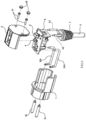
- the core assembly 8 includes a control circuit board 81, a releasing assembly coupled to the control circuit board 81 and a detection assembly, wherein the N-blade 861, the L-blade 862, the L-elastic contact arm 871 and the N-elastic contact arm 872 are respectively fitted to the control circuit board 81.
- the N-blade 861 and the L-blade 862 of the output assembly are connected to the control circuit board 81 through corresponding positioning holes of the releasing coil 821.
- the releasing assembly includes at least a releasing coil (SOL) 821, a releaser 88, a releasing iron core 822 and a releasing spring 823.
- the releasing iron core 822 and the releasing spring 823 are disposed in the releasing coil 821 and can be embedded through a coil baffle 824 to prevent the releasing iron core 822 and the releasing spring 823 from falling off.
- the releasing iron core 822 When the releasing coil 821 generates a magnetic field, the releasing iron core 822 will move along the channel in the releasing coil 821 under the action of the magnetic field force.
- the releaser 88 is used to cooperate with the releasing iron core 822 so as to move in a direction perpendicular to the movement direction of the releasing iron core 822, and then causing the L-elastic contact arm 871 and the N-elastic contact arm 872 of the input assembly overlapped on the two arms of the releaser 88 to deform and contact or engage with the N-blade 861 and the L-blade 862 to switch on the circuit, or vice versa, causing the L-elastic contact arm 871 and the N-elastic contact arm 872 to disengage from the N-blade 861 and the L-blade 862 to switch off the circuit.
- the reset assembly includes at least a reset lever 84 and a reset spring 85 which are cooperated with the releaser 88, wherein one end of the reset lever 84 is inserted into the reset button 3 through the control circuit board 81, and the other end is inserted into the reset spring 85.
- the reset button 3 is pressed down, the reset lever 84 is buckled with the releaser 88, and the L-elastic contact arm 871 and the N-elastic contact arm 872 overlapped on the two arms of the releaser 88 can be lifted upward by the elasticity of the reset spring 85 to realize contact connection with the N-blade 861 and the L-blade 862, thereby obtaining electric power connection between the input end and the output end.
- the releasing coil 821 If leakage current occurs, the releasing coil 821 generates a magnetic field, which drives the releasing iron core 822 to move and release the reset rod 84 from the releaser 88.
- the L-elastic contact arm 871 and the N-elastic contact arm 872 are disconnected from the N-blade 861 and the L-blade 862, thus cutting off the power connection between the input end and the output end.
- the L-elastic contact arm 871 and the N-elastic contact arm 872 are directly connected to the control circuit board 81 and the input end through the detection assembly.
- the detection assembly includes at least a detection coil sheath 831, a detection coil (CT) 832 and a detection coil cover 833.
- the detection coil 832 and the detection coil cover 833 are disposed in the detection coil sheath 831. In this way, the detection coil 832 can detect whether leakage current exists between the phase lines of the L-elastic contact arm 871 and the N-elastic contact arm 872 of the input assembly passing therethrough, thereby driving the leakage protection device to connect or disconnect the power connection.
- the operation principle of the leakage protection device of the present disclosure will be described below with reference to Fig. 8 .
- the power connection between the input end and the output end can be realized by pressing the RESET button.
- the detection coil (CT) detects leakage current in L and N phase lines
- the CT transmits the detected leakage current signal to the processor IC. If the leakage current exceeds the set value, the IC sends out a signal to drive the silicon controlled rectifier (SRC) to be conducted, so that the releasing coil SOL generates a magnetic field to drive the releasing iron core to move and disconnect the power connection between the input end and the output end.
- SRC silicon controlled rectifier
Landscapes
- Engineering & Computer Science (AREA)
- Microelectronics & Electronic Packaging (AREA)
- Breakers (AREA)
Claims (8)
- Leckageschutzvorrichtung, umfassend ein Gehäuse und eine in dem Gehäuse angeordnete Kernbaugruppe (8), wobei die Kernbaugruppe (8) eine Steuerplatine und eine Eingangsbaugruppe und eine Ausgangsbaugruppe umfasst, die mit der Steuerplatine (81) gekoppelt sind, wobei die Leckageschutzvorrichtung eine Rückstellbaugruppe und eine Testbaugruppe umfasst; wobei die Rückstellbaugruppe eine außerhalb des Gehäuses angeordnete Rückstelltaste (3) umfasst und die Testbaugruppe eine außerhalb des Gehäuses angeordnete Testtaste (4) umfasst; und wobei sich die Eingangsbaugruppe in einer ersten Richtung (D1) aus dem Gehäuse heraus erstreckt, wobei die Rückstelltaste (3) und die Testtaste (4) auf der äußeren Umfangsfläche des Gehäuses parallel zur ersten Richtung (D1) angeordnet sind,
wobei die Leckageschutzvorrichtung ferner eine Ablösebaugruppe und eine mit der Steuerplatine (81) gekoppelte Detektionsbaugruppe umfasst; wobei die Eingangsbaugruppe ein Paar elastischer Kontaktarme (871, 872) umfasst, wobei jeder elastische Kontaktarm mit einem beweglichen elektrischen Kontakt versehen ist; wobei die Ausgangsbaugruppe ein Paar Kontaktarme (861, 862) umfasst, wobei jeder Kontaktarm mit einem statischen elektrischen Kontakt versehen ist, um mit dem beweglichen elektrischen Kontakt zusammenzuwirken; und wobei die Ablösebaugruppe mit einem Ablöser (88) versehen ist, um den beweglichen elektrischen Kontakt dazu zu veranlassen, mit dem statischen elektrischen Kontakt in Eingriff zu treten oder von diesem außer Eingriff zu gelangen, und wobei das Paar elastischer Kontaktarme (871, 872) der Eingangsbaugruppe über die Detektionsbaugruppe mit einem Stromversorgungsanschluss verbunden ist. - Leckageschutzvorrichtung gemäß Anspruch 1, wobei die Rückstelltaste (3) und die Testtaste (4) parallel auf der äußeren Umfangsfläche des Gehäuses entlang der ersten Richtung (D1) oder senkrecht zur ersten Richtung (D1) angeordnet sind.
- Leckageschutzvorrichtung gemäß Anspruch 1 oder 2, wobei das Gehäuse so konfiguriert ist, dass es in einer Richtung senkrecht zur ersten Richtung (D1) eine kreisförmige, quadratische, rechteckige oder polygonale Querschnittsform aufweist.
- Leckageschutzvorrichtung gemäß Anspruch 1 oder 2, wobei sich die Ausgangsbaugruppe entlang einer zweiten Richtung (D2) auf der Oberfläche des Gehäuses aus dem Gehäuse heraus erstreckt, auf der die Eingangsbaugruppe, die Rückstelltaste (3) und die Testtaste (4) nicht vorgesehen sind, und wobei die zweite Richtung (D2) parallel zur oder abgewinkelt zur ersten Richtung (D1) verläuft.
- Leckageschutzvorrichtung gemäß Anspruch 4, wobei das Gehäuse einen Gehäusesitz (1) und einen Gehäusedeckel (2) umfasst, die miteinander verbunden sind, wobei der Gehäusedeckel (2) mit einer Öffnung versehen ist, durch die die Rückstelltaste (3) und die Testtaste (4) herausragen, und wobei sich die Ausgangsbaugruppe aus dem Gehäusesitz (1) oder dem Gehäusedeckel (2) heraus erstreckt.
- Leckageschutzvorrichtung gemäß Anspruch 1 oder 2, wobei die Ausgangsbaugruppe eine Ausgangsverdrahtungseinrichtung (6) umfasst, und wobei die Ausgangsverdrahtungseinrichtung (6) einen mit der Kernbaugruppe (8) gekoppelten Ausgangsdraht oder eine mit dem Ausgangsdraht verbundene Verdrahtungsbaugruppe umfasst.
- Leckageschutzvorrichtung gemäß Anspruch 6, wobei die Leckageschutzvorrichtung ferner eine mit der Steuerplatine (81) gekoppelte Ablösespule (821) umfasst, und wobei ein Paar Kontaktarme (861, 862) der Ausgangsbaugruppe über die Ablösespule (821) begrenzt, fixiert und mit der Ausgangsverdrahtungseinrichtung (6) verbunden sind.
- Leckageschutzvorrichtung gemäß Anspruch 6, wobei die Ausgabebaugruppe ferner eine mit der Ausgangsverdrahtungseinrichtung (6) gekoppelte Drahtkarte (7) umfasst, und wobei die Drahtkarte (7) mit dem Gehäuse zusammenwirkend verbunden ist.
Applications Claiming Priority (1)
| Application Number | Priority Date | Filing Date | Title |
|---|---|---|---|
| CN202010229932.9A CN111293465B (zh) | 2020-03-27 | 2020-03-27 | 漏电保护装置 |
Publications (3)
| Publication Number | Publication Date |
|---|---|
| EP3886271A1 EP3886271A1 (de) | 2021-09-29 |
| EP3886271B1 true EP3886271B1 (de) | 2024-11-27 |
| EP3886271C0 EP3886271C0 (de) | 2024-11-27 |
Family
ID=70553859
Family Applications (1)
| Application Number | Title | Priority Date | Filing Date |
|---|---|---|---|
| EP20172918.3A Active EP3886271B1 (de) | 2020-03-27 | 2020-05-05 | Leckageschutzvorrichtung |
Country Status (2)
| Country | Link |
|---|---|
| EP (1) | EP3886271B1 (de) |
| CN (1) | CN111293465B (de) |
Families Citing this family (1)
| Publication number | Priority date | Publication date | Assignee | Title |
|---|---|---|---|---|
| CN114784557B (zh) * | 2022-04-27 | 2023-07-18 | 广东杰创电子有限公司 | 一种具有磁吸功能的防水连接线 |
Family Cites Families (16)
| Publication number | Priority date | Publication date | Assignee | Title |
|---|---|---|---|---|
| FR1429929A (fr) * | 1964-04-14 | 1966-02-25 | Thomson Houston Comp Francaise | Disjoncteur électrique avec système de disjonction perfectionné |
| DE7034601U (de) * | 1970-09-17 | 1971-04-01 | Kober Manpar Ag | Fehlerstromschalter. |
| US6122155A (en) * | 1997-04-22 | 2000-09-19 | Tower Manufacturing Corporation | Mini appliance leakage current interrupter |
| CN1614731A (zh) * | 2004-12-06 | 2005-05-11 | 袁柯 | 漏电保护插座 |
| CN2817116Y (zh) * | 2005-09-12 | 2006-09-13 | 上海益而益电器制造有限公司 | 具有漏电保护功能的电源插头 |
| JP4816246B2 (ja) * | 2006-05-23 | 2011-11-16 | 富士電機機器制御株式会社 | 漏電遮断器 |
| CN200965956Y (zh) * | 2006-10-23 | 2007-10-24 | 上海益而益电器制造有限公司 | 具有漏电保护功能的电源插头 |
| CN101483297B (zh) * | 2008-01-11 | 2012-09-19 | 黄华道 | 具有漏电保护功能的电源插头 |
| CN102509967A (zh) * | 2011-11-20 | 2012-06-20 | 黄德富 | 漏电保护插座 |
| CN202840126U (zh) * | 2012-08-14 | 2013-03-27 | 中山市拓昊电器有限公司 | 一种具有漏电保护功能的插头 |
| CN203521795U (zh) * | 2013-10-18 | 2014-04-02 | 益而益(集团)有限公司 | 具有漏电保护功能的电源插头 |
| CN105609382B (zh) * | 2015-09-29 | 2017-10-31 | 嘉兴首信电气科技有限公司 | 一种电路保护装置 |
| CN106602508B (zh) * | 2015-10-19 | 2020-07-03 | 苏州益而益电器制造有限公司 | 漏电保护器 |
| CN109390730B (zh) * | 2017-08-14 | 2024-02-27 | 苏州益而益电器制造有限公司 | 漏电保护插头 |
| US10170265B2 (en) * | 2016-12-14 | 2019-01-01 | Chengli Li | Leakage current protection device |
| CN211629343U (zh) * | 2020-03-27 | 2020-10-02 | 苏州益而益电器制造有限公司 | 漏电保护装置 |
-
2020
- 2020-03-27 CN CN202010229932.9A patent/CN111293465B/zh active Active
- 2020-05-05 EP EP20172918.3A patent/EP3886271B1/de active Active
Also Published As
| Publication number | Publication date |
|---|---|
| CN111293465A (zh) | 2020-06-16 |
| EP3886271C0 (de) | 2024-11-27 |
| EP3886271A1 (de) | 2021-09-29 |
| CN111293465B (zh) | 2025-05-27 |
Similar Documents
| Publication | Publication Date | Title |
|---|---|---|
| CN200993948Y (zh) | 安全型接地故障断路器 | |
| EP2437359A1 (de) | Netzstecker mit verlustschutzfunktion | |
| US8213139B2 (en) | Leakage current protection plug and interrupt protection plug contact spring structure | |
| US20210225606A1 (en) | Leakage current protection device employing a pivoting actuator in the trip assembly | |
| EP3886271B1 (de) | Leckageschutzvorrichtung | |
| CN211700699U (zh) | 漏电保护装置 | |
| CN101958212A (zh) | 插座式剩余电流断路器 | |
| US12340963B2 (en) | Trip and reset mechanism for leakage current detection and interruption device | |
| CN111463612B (zh) | 漏电保护装置 | |
| CN109411966A (zh) | 漏电保护插头 | |
| CN211629343U (zh) | 漏电保护装置 | |
| CN201532918U (zh) | 插座式剩余电流断路器 | |
| CN203553079U (zh) | 两极集成多功能断路器 | |
| CN209418912U (zh) | 一种具有组合开关的插座 | |
| CN105203813A (zh) | 紧凑式表、电气插拔式计量设备 | |
| CN220711106U (zh) | 具有故障显示功能的漏电保护装置 | |
| CN111740277A (zh) | 一种漏电保护插头 | |
| CN208001053U (zh) | 带漏电保护装置的插座 | |
| CN207719800U (zh) | 交流三相电动机缺相保护器及控制电路 | |
| CN211958029U (zh) | 一种具有五孔插入检测功能的插座 | |
| CN213184836U (zh) | 一种基于服务器上电的电源线通断装置 | |
| JP7657162B2 (ja) | Usb充電器付ケーブルスイッチ | |
| US20250233405A1 (en) | Leakage protection device with load-end functions | |
| CN216390479U (zh) | 漏电保护装置 | |
| CN217607153U (zh) | 自动化装配的漏电保护装置 |
Legal Events
| Date | Code | Title | Description |
|---|---|---|---|
| PUAI | Public reference made under article 153(3) epc to a published international application that has entered the european phase |
Free format text: ORIGINAL CODE: 0009012 |
|
| STAA | Information on the status of an ep patent application or granted ep patent |
Free format text: STATUS: REQUEST FOR EXAMINATION WAS MADE |
|
| 17P | Request for examination filed |
Effective date: 20200505 |
|
| AK | Designated contracting states |
Kind code of ref document: A1 Designated state(s): AL AT BE BG CH CY CZ DE DK EE ES FI FR GB GR HR HU IE IS IT LI LT LU LV MC MK MT NL NO PL PT RO RS SE SI SK SM TR |
|
| RBV | Designated contracting states (corrected) |
Designated state(s): AL AT BE BG CH CY CZ DE DK EE ES FI FR GB GR HR HU IE IS IT LI LT LU LV MC MK MT NL NO PL PT RO RS SE SI SK SM TR |
|
| STAA | Information on the status of an ep patent application or granted ep patent |
Free format text: STATUS: EXAMINATION IS IN PROGRESS |
|
| 17Q | First examination report despatched |
Effective date: 20230816 |
|
| GRAP | Despatch of communication of intention to grant a patent |
Free format text: ORIGINAL CODE: EPIDOSNIGR1 |
|
| STAA | Information on the status of an ep patent application or granted ep patent |
Free format text: STATUS: GRANT OF PATENT IS INTENDED |
|
| INTG | Intention to grant announced |
Effective date: 20240723 |
|
| RIN1 | Information on inventor provided before grant (corrected) |
Inventor name: NIE, SHENGYUN Inventor name: ZHANG, XIAOMING Inventor name: LI, CHENGLI |
|
| GRAS | Grant fee paid |
Free format text: ORIGINAL CODE: EPIDOSNIGR3 |
|
| GRAA | (expected) grant |
Free format text: ORIGINAL CODE: 0009210 |
|
| STAA | Information on the status of an ep patent application or granted ep patent |
Free format text: STATUS: THE PATENT HAS BEEN GRANTED |
|
| AK | Designated contracting states |
Kind code of ref document: B1 Designated state(s): AL AT BE BG CH CY CZ DE DK EE ES FI FR GB GR HR HU IE IS IT LI LT LU LV MC MK MT NL NO PL PT RO RS SE SI SK SM TR |
|
| REG | Reference to a national code |
Ref country code: GB Ref legal event code: FG4D |
|
| REG | Reference to a national code |
Ref country code: CH Ref legal event code: EP |
|
| REG | Reference to a national code |
Ref country code: IE Ref legal event code: FG4D |
|
| REG | Reference to a national code |
Ref country code: DE Ref legal event code: R096 Ref document number: 602020041930 Country of ref document: DE |
|
| U01 | Request for unitary effect filed |
Effective date: 20241128 |
|
| U07 | Unitary effect registered |
Designated state(s): AT BE BG DE DK EE FI FR IT LT LU LV MT NL PT RO SE SI Effective date: 20241209 |
|
| PG25 | Lapsed in a contracting state [announced via postgrant information from national office to epo] |
Ref country code: IS Free format text: LAPSE BECAUSE OF FAILURE TO SUBMIT A TRANSLATION OF THE DESCRIPTION OR TO PAY THE FEE WITHIN THE PRESCRIBED TIME-LIMIT Effective date: 20250327 Ref country code: HR Free format text: LAPSE BECAUSE OF FAILURE TO SUBMIT A TRANSLATION OF THE DESCRIPTION OR TO PAY THE FEE WITHIN THE PRESCRIBED TIME-LIMIT Effective date: 20241127 |
|
| PG25 | Lapsed in a contracting state [announced via postgrant information from national office to epo] |
Ref country code: ES Free format text: LAPSE BECAUSE OF FAILURE TO SUBMIT A TRANSLATION OF THE DESCRIPTION OR TO PAY THE FEE WITHIN THE PRESCRIBED TIME-LIMIT Effective date: 20241127 |
|
| PG25 | Lapsed in a contracting state [announced via postgrant information from national office to epo] |
Ref country code: NO Free format text: LAPSE BECAUSE OF FAILURE TO SUBMIT A TRANSLATION OF THE DESCRIPTION OR TO PAY THE FEE WITHIN THE PRESCRIBED TIME-LIMIT Effective date: 20250227 |
|
| PG25 | Lapsed in a contracting state [announced via postgrant information from national office to epo] |
Ref country code: GR Free format text: LAPSE BECAUSE OF FAILURE TO SUBMIT A TRANSLATION OF THE DESCRIPTION OR TO PAY THE FEE WITHIN THE PRESCRIBED TIME-LIMIT Effective date: 20250228 |
|
| PG25 | Lapsed in a contracting state [announced via postgrant information from national office to epo] |
Ref country code: PL Free format text: LAPSE BECAUSE OF FAILURE TO SUBMIT A TRANSLATION OF THE DESCRIPTION OR TO PAY THE FEE WITHIN THE PRESCRIBED TIME-LIMIT Effective date: 20241127 |
|
| PG25 | Lapsed in a contracting state [announced via postgrant information from national office to epo] |
Ref country code: RS Free format text: LAPSE BECAUSE OF FAILURE TO SUBMIT A TRANSLATION OF THE DESCRIPTION OR TO PAY THE FEE WITHIN THE PRESCRIBED TIME-LIMIT Effective date: 20250227 |
|
| U20 | Renewal fee for the european patent with unitary effect paid |
Year of fee payment: 6 Effective date: 20250416 |
|
| PG25 | Lapsed in a contracting state [announced via postgrant information from national office to epo] |
Ref country code: SM Free format text: LAPSE BECAUSE OF FAILURE TO SUBMIT A TRANSLATION OF THE DESCRIPTION OR TO PAY THE FEE WITHIN THE PRESCRIBED TIME-LIMIT Effective date: 20241127 |
|
| PG25 | Lapsed in a contracting state [announced via postgrant information from national office to epo] |
Ref country code: SK Free format text: LAPSE BECAUSE OF FAILURE TO SUBMIT A TRANSLATION OF THE DESCRIPTION OR TO PAY THE FEE WITHIN THE PRESCRIBED TIME-LIMIT Effective date: 20241127 |
|
| PG25 | Lapsed in a contracting state [announced via postgrant information from national office to epo] |
Ref country code: CZ Free format text: LAPSE BECAUSE OF FAILURE TO SUBMIT A TRANSLATION OF THE DESCRIPTION OR TO PAY THE FEE WITHIN THE PRESCRIBED TIME-LIMIT Effective date: 20241127 |
|
| PLBE | No opposition filed within time limit |
Free format text: ORIGINAL CODE: 0009261 |
|
| STAA | Information on the status of an ep patent application or granted ep patent |
Free format text: STATUS: NO OPPOSITION FILED WITHIN TIME LIMIT |
|
| 26N | No opposition filed |
Effective date: 20250828 |