EP3886202B1 - Fluid spring pressurized battery stack - Google Patents
Fluid spring pressurized battery stack Download PDFInfo
- Publication number
- EP3886202B1 EP3886202B1 EP20166297.0A EP20166297A EP3886202B1 EP 3886202 B1 EP3886202 B1 EP 3886202B1 EP 20166297 A EP20166297 A EP 20166297A EP 3886202 B1 EP3886202 B1 EP 3886202B1
- Authority
- EP
- European Patent Office
- Prior art keywords
- fluid
- pressure
- battery
- stack
- sensor
- Prior art date
- Legal status (The legal status is an assumption and is not a legal conclusion. Google has not performed a legal analysis and makes no representation as to the accuracy of the status listed.)
- Active
Links
Images


Classifications
-
- H—ELECTRICITY
- H01—ELECTRIC ELEMENTS
- H01M—PROCESSES OR MEANS, e.g. BATTERIES, FOR THE DIRECT CONVERSION OF CHEMICAL ENERGY INTO ELECTRICAL ENERGY
- H01M50/00—Constructional details or processes of manufacture of the non-active parts of electrochemical cells other than fuel cells, e.g. hybrid cells
- H01M50/20—Mountings; Secondary casings or frames; Racks, modules or packs; Suspension devices; Shock absorbers; Transport or carrying devices; Holders
- H01M50/233—Mountings; Secondary casings or frames; Racks, modules or packs; Suspension devices; Shock absorbers; Transport or carrying devices; Holders characterised by physical properties of casings or racks, e.g. dimensions
- H01M50/242—Mountings; Secondary casings or frames; Racks, modules or packs; Suspension devices; Shock absorbers; Transport or carrying devices; Holders characterised by physical properties of casings or racks, e.g. dimensions adapted for protecting batteries against vibrations, collision impact or swelling
-
- H—ELECTRICITY
- H01—ELECTRIC ELEMENTS
- H01M—PROCESSES OR MEANS, e.g. BATTERIES, FOR THE DIRECT CONVERSION OF CHEMICAL ENERGY INTO ELECTRICAL ENERGY
- H01M10/00—Secondary cells; Manufacture thereof
- H01M10/04—Construction or manufacture in general
- H01M10/0481—Compression means other than compression means for stacks of electrodes and separators
-
- H—ELECTRICITY
- H01—ELECTRIC ELEMENTS
- H01M—PROCESSES OR MEANS, e.g. BATTERIES, FOR THE DIRECT CONVERSION OF CHEMICAL ENERGY INTO ELECTRICAL ENERGY
- H01M10/00—Secondary cells; Manufacture thereof
- H01M10/42—Methods or arrangements for servicing or maintenance of secondary cells or secondary half-cells
- H01M10/425—Structural combination with electronic components, e.g. electronic circuits integrated to the outside of the casing
- H01M10/4257—Smart batteries, e.g. electronic circuits inside the housing of the cells or batteries
-
- H—ELECTRICITY
- H01—ELECTRIC ELEMENTS
- H01M—PROCESSES OR MEANS, e.g. BATTERIES, FOR THE DIRECT CONVERSION OF CHEMICAL ENERGY INTO ELECTRICAL ENERGY
- H01M10/00—Secondary cells; Manufacture thereof
- H01M10/42—Methods or arrangements for servicing or maintenance of secondary cells or secondary half-cells
- H01M10/44—Methods for charging or discharging
-
- H—ELECTRICITY
- H01—ELECTRIC ELEMENTS
- H01M—PROCESSES OR MEANS, e.g. BATTERIES, FOR THE DIRECT CONVERSION OF CHEMICAL ENERGY INTO ELECTRICAL ENERGY
- H01M10/00—Secondary cells; Manufacture thereof
- H01M10/42—Methods or arrangements for servicing or maintenance of secondary cells or secondary half-cells
- H01M10/48—Accumulators combined with arrangements for measuring, testing or indicating the condition of cells, e.g. the level or density of the electrolyte
- H01M10/482—Accumulators combined with arrangements for measuring, testing or indicating the condition of cells, e.g. the level or density of the electrolyte for several batteries or cells simultaneously or sequentially
-
- H—ELECTRICITY
- H01—ELECTRIC ELEMENTS
- H01M—PROCESSES OR MEANS, e.g. BATTERIES, FOR THE DIRECT CONVERSION OF CHEMICAL ENERGY INTO ELECTRICAL ENERGY
- H01M10/00—Secondary cells; Manufacture thereof
- H01M10/42—Methods or arrangements for servicing or maintenance of secondary cells or secondary half-cells
- H01M10/48—Accumulators combined with arrangements for measuring, testing or indicating the condition of cells, e.g. the level or density of the electrolyte
- H01M10/486—Accumulators combined with arrangements for measuring, testing or indicating the condition of cells, e.g. the level or density of the electrolyte for measuring temperature
-
- H—ELECTRICITY
- H01—ELECTRIC ELEMENTS
- H01M—PROCESSES OR MEANS, e.g. BATTERIES, FOR THE DIRECT CONVERSION OF CHEMICAL ENERGY INTO ELECTRICAL ENERGY
- H01M50/00—Constructional details or processes of manufacture of the non-active parts of electrochemical cells other than fuel cells, e.g. hybrid cells
- H01M50/20—Mountings; Secondary casings or frames; Racks, modules or packs; Suspension devices; Shock absorbers; Transport or carrying devices; Holders
- H01M50/204—Racks, modules or packs for multiple batteries or multiple cells
- H01M50/207—Racks, modules or packs for multiple batteries or multiple cells characterised by their shape
- H01M50/209—Racks, modules or packs for multiple batteries or multiple cells characterised by their shape adapted for prismatic or rectangular cells
-
- H—ELECTRICITY
- H01—ELECTRIC ELEMENTS
- H01M—PROCESSES OR MEANS, e.g. BATTERIES, FOR THE DIRECT CONVERSION OF CHEMICAL ENERGY INTO ELECTRICAL ENERGY
- H01M50/00—Constructional details or processes of manufacture of the non-active parts of electrochemical cells other than fuel cells, e.g. hybrid cells
- H01M50/20—Mountings; Secondary casings or frames; Racks, modules or packs; Suspension devices; Shock absorbers; Transport or carrying devices; Holders
- H01M50/204—Racks, modules or packs for multiple batteries or multiple cells
- H01M50/207—Racks, modules or packs for multiple batteries or multiple cells characterised by their shape
- H01M50/211—Racks, modules or packs for multiple batteries or multiple cells characterised by their shape adapted for pouch cells
-
- H—ELECTRICITY
- H01—ELECTRIC ELEMENTS
- H01M—PROCESSES OR MEANS, e.g. BATTERIES, FOR THE DIRECT CONVERSION OF CHEMICAL ENERGY INTO ELECTRICAL ENERGY
- H01M50/00—Constructional details or processes of manufacture of the non-active parts of electrochemical cells other than fuel cells, e.g. hybrid cells
- H01M50/20—Mountings; Secondary casings or frames; Racks, modules or packs; Suspension devices; Shock absorbers; Transport or carrying devices; Holders
- H01M50/249—Mountings; Secondary casings or frames; Racks, modules or packs; Suspension devices; Shock absorbers; Transport or carrying devices; Holders specially adapted for aircraft or vehicles, e.g. cars or trains
-
- H—ELECTRICITY
- H01—ELECTRIC ELEMENTS
- H01M—PROCESSES OR MEANS, e.g. BATTERIES, FOR THE DIRECT CONVERSION OF CHEMICAL ENERGY INTO ELECTRICAL ENERGY
- H01M10/00—Secondary cells; Manufacture thereof
- H01M10/42—Methods or arrangements for servicing or maintenance of secondary cells or secondary half-cells
- H01M10/425—Structural combination with electronic components, e.g. electronic circuits integrated to the outside of the casing
- H01M2010/4271—Battery management systems including electronic circuits, e.g. control of current or voltage to keep battery in healthy state, cell balancing
-
- H—ELECTRICITY
- H01—ELECTRIC ELEMENTS
- H01M—PROCESSES OR MEANS, e.g. BATTERIES, FOR THE DIRECT CONVERSION OF CHEMICAL ENERGY INTO ELECTRICAL ENERGY
- H01M2200/00—Safety devices for primary or secondary batteries
- H01M2200/10—Temperature sensitive devices
-
- H—ELECTRICITY
- H01—ELECTRIC ELEMENTS
- H01M—PROCESSES OR MEANS, e.g. BATTERIES, FOR THE DIRECT CONVERSION OF CHEMICAL ENERGY INTO ELECTRICAL ENERGY
- H01M2200/00—Safety devices for primary or secondary batteries
- H01M2200/20—Pressure-sensitive devices
-
- H—ELECTRICITY
- H01—ELECTRIC ELEMENTS
- H01M—PROCESSES OR MEANS, e.g. BATTERIES, FOR THE DIRECT CONVERSION OF CHEMICAL ENERGY INTO ELECTRICAL ENERGY
- H01M2220/00—Batteries for particular applications
- H01M2220/20—Batteries in motive systems, e.g. vehicle, ship, plane
-
- Y—GENERAL TAGGING OF NEW TECHNOLOGICAL DEVELOPMENTS; GENERAL TAGGING OF CROSS-SECTIONAL TECHNOLOGIES SPANNING OVER SEVERAL SECTIONS OF THE IPC; TECHNICAL SUBJECTS COVERED BY FORMER USPC CROSS-REFERENCE ART COLLECTIONS [XRACs] AND DIGESTS
- Y02—TECHNOLOGIES OR APPLICATIONS FOR MITIGATION OR ADAPTATION AGAINST CLIMATE CHANGE
- Y02E—REDUCTION OF GREENHOUSE GAS [GHG] EMISSIONS, RELATED TO ENERGY GENERATION, TRANSMISSION OR DISTRIBUTION
- Y02E60/00—Enabling technologies; Technologies with a potential or indirect contribution to GHG emissions mitigation
- Y02E60/10—Energy storage using batteries
-
- Y—GENERAL TAGGING OF NEW TECHNOLOGICAL DEVELOPMENTS; GENERAL TAGGING OF CROSS-SECTIONAL TECHNOLOGIES SPANNING OVER SEVERAL SECTIONS OF THE IPC; TECHNICAL SUBJECTS COVERED BY FORMER USPC CROSS-REFERENCE ART COLLECTIONS [XRACs] AND DIGESTS
- Y02—TECHNOLOGIES OR APPLICATIONS FOR MITIGATION OR ADAPTATION AGAINST CLIMATE CHANGE
- Y02P—CLIMATE CHANGE MITIGATION TECHNOLOGIES IN THE PRODUCTION OR PROCESSING OF GOODS
- Y02P70/00—Climate change mitigation technologies in the production process for final industrial or consumer products
- Y02P70/50—Manufacturing or production processes characterised by the final manufactured product
Definitions
- the present invention relates to a battery system or battery module comprising a stack of battery cells, wherein one or several fluid springs are integrated into the stack of battery cells to allow for a control of the pressure exerted on the battery cells of the stack.
- the one or several fluid springs comprise an elastic device providing a maximum pressure, even when the fluid in the fluid springs is not pressurized (i. e., when the pressure of the fluid in a fluid spring equals the pressure of the ambient air).
- the pressure exerted by the fluid springs on the adjacent battery cells is controlled by an adjustable underpressure of the fluid in the fluid springs.
- the fluid pressure in the fluid springs is decreased, when a safety critical situation such as a crash of the vehicle or a thermal runaway in the battery system is detected.
- the present invention further relates to methods for operating the afore-described battery system or battery module.
- the invention is related to a battery pack comprising the battery system and to a vehicle including a battery pack or a battery system as defined above.
- Electric-vehicle batteries differ from starting, lighting, and ignition batteries because they are designed to give power over sustained periods of time.
- a rechargeable or secondary battery differs from a primary battery in that it can be repeatedly charged and discharged, while the latter provides only an irreversible conversion of chemical to electrical energy.
- Low-capacity rechargeable batteries are used as power supply for small electronic devices, such as cellular phones, notebook computers and camcorders, while high-capacity rechargeable batteries are used as the power supply for hybrid vehicles and the like.
- rechargeable batteries include an electrode assembly including a positive electrode, a negative electrode, and a separator interposed between the positive and negative electrodes, a case receiving the electrode assembly, and an electrode terminal electrically connected to the electrode assembly.
- An electrolyte solution is injected into the case in order to enable charging and discharging of the battery via an electrochemical reaction of the positive electrode, the negative electrode, and the electrolyte solution.
- the shape of the case e.g. cylindrical or rectangular, depends on the battery's intended purpose. Lithium-ion (and similar lithium polymer) batteries, widely known via their use in laptops and consumer electronics, dominate the most recent group of electric vehicles in development.
- solid state cells can be employed in a battery.
- a solid state battery can be defined via the following characteristics. The principal difference between a conventional Li-ion cell and an all solid state Li-ion cell is that the later contains no liquid electrolyte. Instead, the electrolyte is a solid state electrolyte.
- the solid state electrolyte may be a ceramic (e. g., sulfides, oxides, phosphates) or solid polymer (e. g., polyethylene oxide (PEO)), or a polymer gel (e. g. poly(vinylidenefluoride)-hexafluoropropylene (PVdF(HFP))).
- the cathode material deployed in a solid-state may be same as in conventional Li-ion batteries. However, the cathode particles are not soaked with liquid electrolyte but embedded in the solid electrolyte matrix. Further, the anode of a solid state cell differs from the anode of a conventional Li-ion cell. In a conventional cell, the anode is composed of Graphite or silicon particles. In a solid state cell, however, the anode comprises a thin Li-metal film. Moreover, a solid state cell has no dedicated separator. The solid electrolyte acts as a separator (thus the solid state electrolyte is not electrically conductive).
- Rechargeable batteries may be used as a battery module formed of a plurality of unit battery cells coupled in series and/or in parallel so as to provide a high energy density, in particular for motor driving of a hybrid vehicle. That is, the battery module is formed by interconnecting the electrode terminals of the plurality of unit battery cells depending on a required amount of power and in order to realize a high-power rechargeable battery.
- a battery pack is a set of any number of (preferably identical) battery modules. They may be configured in a series, parallel or a mixture of both to deliver the desired voltage, capacity, or power density. Components of battery packs include the individual battery modules, and the interconnects, which provide electrical conductivity between them.
- Mechanical integration of battery modules may be achieved by providing a carrier framework and by positioning the battery modules thereon. Fixing the battery cells or battery modules may be achieved by fitted depressions in the framework or by mechanical interconnectors such as bolts or screws. Alternatively, the battery modules are confined by fastening side plates to lateral sides of the carrier framework. Further, cover plates may be fixed atop and below the battery modules.
- the carrier framework of the battery pack is mounted to a carrying structure of the vehicle.
- the mechanical connection may be established from the bottom side by for example bolts passing through the carrier framework of the battery pack.
- the framework is usually made of aluminum or an aluminum alloy to lower the total weight of the construction. Also, the framework may be made of a steel alloy for improved safety and robustness.
- Battery systems according to the prior art usually comprise a battery housing that serves as enclosure to seal the battery system against the environment and provides structural protection of the battery system's components.
- Housed battery systems are usually mounted as a whole into their application environment, e.g. an electric vehicle.
- defect system parts e. g. a defect battery submodule
- the replacement of defect system parts requires dismounting the whole battery system and removal of its housing first.
- Even defects of small and/or cheap system parts might then lead to dismounting and replacement of the complete battery system and its separate repair.
- As high-capacity battery systems are expensive, large and heavy, said procedure proves burdensome and the storage, e. g. in the mechanic's workshop, of the bulky battery systems becomes difficult.
- Battery systems usually comprise a battery management system (BMS) and/or battery management unit (BMU) for processing the aforementioned information.
- the BMS/BMU may communicate to the controllers of the various electrical consumers via a suitable communication bus, e.g. a SPI or CAN interface.
- the BMS/BMU may further communicate with each of the battery submodules, particularly with a cell supervision circuit (CSC) of each battery submodule.
- the CSC may be further connected to a cell connection and sensing unit (CCU) of a battery submodule that interconnects the battery cells of the battery submodule.
- CSC cell supervision circuit
- the BMS/BMU is provided for managing the battery pack, such as by protecting the battery from operating outside its safe operating area, monitoring its state, calculating secondary data, reporting that data, controlling its environment, authenticating it and/or balancing it.
- a thermal management system is required to safely use the at least one battery module by efficiently emitting, discharging and/or dissipating heat generated from its rechargeable batteries. If the heat emission/discharge/dissipation is not sufficiently performed, temperature deviations occur between respective battery cells, such that the at least one battery module cannot generate a desired amount of power. In addition, an increase of the internal temperature can lead to abnormal reactions occurring therein and thus charging and discharging performance of the rechargeable deteriorates and the life-span of the rechargeable battery is shortened. Thus, cell cooling for effectively emitting/discharging/ dissipating heat from the cells is required.
- a typical automotive battery module (in the following also simply referred to as "module") consists of several stacked cells. To achieve a desired capacity and voltage of the module, busbars connect the cells electrically in series or in parallel. The modules may be further connected in series, until the desired system voltage of the battery pack is reached.
- each of the battery cells comprised in this stack - is pressed with a mechanical pressure (e. g. 100 kPa).
- a mechanical pressure e. g. 100 kPa.
- Solid state battery cells cf. above for a definition of which
- mechanical pressures typically in the range of 2 MPa to 3 MPa
- the battery cells in the following also simply referred to as “cells”
- the battery cells may expand during charging and shrink during discharge (e. g. by 5 %), leading in particular to a change of the thickness of the cells.
- the thickness of the cell is superimposed by slow irreversible swelling due to ageing of the electrode materials.
- the change of the thickness of cells results in a dimensional change of the stack.
- the stack is typically accommodated in a carrier framework or pack frame (see above) with confined dimensions, the carrier framework thus acting as a restrainer, which imposes a mechanical restraining on the stack and the cells comprised in the stack.
- the expansion or shrink of the battery cells affects the pressure, which the battery cells exert to one another in the stack.
- the dimensional change of the stack creates different stresses on the mechanical restraining of the stack and on the cells.
- the change of stress depends on the stiffness of the cells and restrainer; the relation between stress change and the stiffness of the cells as well as of the restrainer being describable, in good approximation, by Hook's law.
- One possibility to control the stress on the cells used in the state of the art is to apply the pressure by means of flat pressure plates, e. g., end plates arranged in front of the first cell and after the last cell of the stack.
- flat pressure plates e. g., end plates arranged in front of the first cell and after the last cell of the stack.
- those plates may bend and the resulting pressure on the outermost cell or cells becomes non-uniform.
- Non-uniform pressure reduces the performance of the cell-stack in particular with regard to safety and/or ageing.
- the afore-described disadvantages are especially pronounced in stacks with solid state cells, which require even higher pressures during operation (see above).
- a possibility to gain improved control over the pressure prevailing in the stack of battery cells is the integration of fluid springs such as air springs or air cushions in the stack of cells.
- the pressure of the fluid within the fluid springs can be controlled externally, which allows for an adaption of the overall-pressure exerted on the cells in the stack.
- WO 2019/017994 A1 provides apparatuses and methods useful for managing pressure in electrochemical devices.
- This invention provides a battery system, a method for operating a battery system, a battery pack and a vehicle as defined in independent claims 1, 8, 11 and 12, respectively. Preferred embodiments are defined in dependent claims 2-7, 9 and 10.
- a battery system or battery module for use in a vehicle comprising: a stack comprising a plurality of battery cells being stacked along a virtual reference axis; a pack frame comprising a first end plate and a second end plate; one or more fluid springs configured for holding a fluid; one or more fluid pressure adjusting means for adjusting a fluid pressure within at least one fluid spring; and a control unit configured for controlling the one or more fluid pressure adjusting means.
- the stack is placed between the first end plate and the second endplate.
- Each of the one or more fluid springs is positioned between the first endplate and the second end plate, and is configured for exerting a pressure on at least one of the battery cells in a direction along the reference axis.
- Each of the fluid pressure adjusting means is connected to one or more fluid springs.
- the control unit is configured for receiving a safety check signal indicating a negative acceleration from at least one safety check sensor comprising an acceleration sensor configured to detect a negative acceleration with an absolute acceleration value equal to or larger than a predefined positive value.
- the control unit is further configured for evaluating, whether one or more received safety check signal(s), which indicate a negative acceleration, may indicate a safety critical situation, and for operating, upon evaluation that the safety check signal(s) indicating a negative acceleration may indicate a safety critical situation, the fluid pressure adjusting means such that the fluid pressure in the fluid springs is decreased.
- an alternative battery system wherein at least one of the fluid springs comprises an elastic device.
- the elastic device may be foam.
- Each of the fluid pressure adjusting means being connected to one or more fluid springs comprising an elastic device is configured to generate or to adjust, when the one or more connected fluid springs each hold a fluid, an pressure in the fluid within the connected fluid springs, wherein the pressure is smaller than or at maximum equal to the pressure of the ambient atmosphere.
- a battery cell placed next to an end plate does not exclude that another different element such as a fluid spring is placed between the battery cell and the end plate.
- pressure as used throughout this document shall refer to mechanical contact pressure, wherein the mechanical contact pressure may be caused by an immediate contact between two elements or immediately, i. e., the pressure is transferred from one element to another element via one or more intermediate elements.
- underpressure of the fluid of a fluid spring shall refer, here and throughout the whole document, to a range of pressures being smaller than the pressure of the ambient atmosphere of the fluid spring or at maximum equal to the pressure of the ambient atmosphere of the fluid spring.
- the pressure of the ambient atmosphere of the fluid spring typically corresponds to the pressure of the ambient air of the battery system.
- the actual pressure exerted from a fluid spring to the one or two adjacent battery cells corresponds, of course, from the (anti-)pressure exerted from the adjacent cells on the fluid spring.
- the pressure provided by this fluid spring depends on the situation, and in particular on the space left for the fluid spring between two elements (e. g., cells) adjacent to the fluid spring along the reference axis.
- the expression "may indicate a safety critical situation” may in particular denote that the evaluation of the safety check signal(s) performed by the control unit, a probability or likeness for a safety critical event in the vehicle or of the vehicle is estimated, and the measured / received safety check signal(s) are classified as safety critical, if said probability or likeness exceeds a predefined value, e. g., 50 %, 80 %, or 90 %.
- safety critical situation shall refer to each event that bears a risk for the vehicle itself and/or the passengers/driver of the vehicle.
- the acceleration sensor acts as a crash sensor.
- the acceleration sensor detects and, upon detection, sends a safety check signal to the connected control unit- negative accelerations of the vehicle (or, equivalently, of the battery system employed in the vehicle) equal to or below -90 m / s 2 , or, in other words, detect a negative acceleration with an absolute value equal to or larger than +90 m / s 2 .
- the acceleration sensor may also send, e. g., in predefined time intervals, the measured acceleration independent from its value, and the control unit evaluates whether or not the measured acceleration or acceleration pattern may indicate a crash of the vehicle.
- the elastic device has a predefined Young's modulus.
- the Young's modulus may be a temperature dependent function.
- the Young's modulus may also be a function depending on a spatial position.
- the Young's modulus is chosen so as to be constant over the entire extend of the elastic device in a plane perpendicular to the reference direction.
- the stack is placed between the first end plate and the second endplate such that the first battery cell of the stack is, when viewed along the reference axis, positioned next to the first end plate and the last battery cell of the stack is, when viewed along the reference axis, positioned next to the second end plate.
- the battery system may further comprise at least one fluid pressure sensor configured to measure a fluid pressure being present in at least one of the fluid springs; wherein the control unit is configured for receiving a pressure signal corresponding to the pressure being measured from each of the fluid pressure sensors; and wherein the control unit is further configured to control, dependent on the one or more received pressure signals, the one or more fluid pressure adjusting means.
- the control unit may be configured to detect, from the pressure signal provided from each of the fluid pressure sensors, a pressure change in the fluid of the fluid springs to which the fluid pressure sensors are connected. Also, the control unit is further configured to control at least one of the fluid pressure adjusting means such that upon detection of a pressure increase by at least one of the fluid pressure sensors, the fluid adjusting pressure means decreases the pressure of fluid within the fluid springs connected to the respective fluid adjusting pressure means.
- the underpressure is increased (i. e., the pressure is decreased), resulting in a decrease of the overall-pressure composed of the pressure caused by the elastic device and the pressure within the fluid.
- the fluid pressure has been equal to the pressure of the ambient atmosphere or has been even higher
- an underpressure i. e., a pressure lower or than or equal to the pressure of the ambient atmosphere is being generated in the fluid after the detection of a pressure increase in the stack.
- the relation between the measured pressure increase and the pressure decrease in the fluid spring(s) triggered as a response to the measured pressure increase may be linear.
- pressure change shall encompass, in this context, both, the case of a pressure increase and the case of a pressure decrease.
- control unit is configured to control at least one of the fluid pressure adjusting means such that, upon detection of a pressure decrease by at least one of the fluid pressure sensors, the fluid adjusting pressure means increases the pressure of fluid within the fluid springs connected to the respective fluid adjusting pressure means.
- the relation between the measured pressure decrease and the pressure increase in the fluid spring(s) triggered as a response to the measured pressure increase may be linear, at least up to a pressure equal to the pressure of the ambient atmosphere.
- At least one of the fluid springs is placed, viewed along the reference axis, between two adjacent battery cells.
- the battery system may comprise only a single fluid spring in this case.
- the battery system may comprise only a single fluid spring in this case.
- one fluid spring is placed between the first end plate and the first battery cell of the stack; and a further fluid spring is placed between the second end plate and the last battery cell of the stack.
- the battery system may comprise only two fluid springs in this case.
- At least one positioning plate is placed, viewed along the reference axis, between two adjacent battery cells.
- the battery system may comprise only a single positioning plate in this case.
- the battery system may comprise only a single positioning plate in this case.
- each of the fluid springs are in fluid communication with each other.
- This embodiment has the advantage that a single fluid adjusting pressure means is sufficient to control each of the fluid springs, and the underpressure of the fluid within the fluid springs is equal for each of the fluid springs.
- the fluid may be a non-compressible fluid or a compressible fluid.
- the non-compressible fluid may be air.
- At least one of the fluid pressure adjusting means comprises a vacuum pump, a valve or a compressor.
- At least one fluid pressure sensor is connected to one or more of the fluid springs.
- the battery cells are solid state battery cells.
- each of the battery cells has a prism-shaped geometry or a cylindrical geometry, wherein the base areas extend perpendicular to the reference axis.
- each of the fluid springs has a prism-shaped geometry or a cylindrical geometry, wherein the base areas extend perpendicular to the reference axis; and each of the fluid springs is positioned such that for each battery cell being in contact with that fluid cell, the entire base area of that battery cell is in contact with the adjacent base area of the fluid spring.
- control unit is integrated into the BMU or BMS of the battery system or the battery pack comprising the battery system.
- At least one safety check sensor comprises a temperature sensor configured to measure the temperature of the stack of battery cells or to measure the temperature of at least one of the battery cells comprised in the stack; and the control unit evaluates, whether or not the temperature or temperature pattern measured by at least one temperature sensor may indicate a safety critical thermal event such as a thermal runaway.
- At least one safety check sensor comprises a cell voltage sensor configured for measuring the voltage or voltage pattern over one or more cells of the battery system.
- At least one safety check sensor comprises a current sensor configured for measuring the current or current pattern produced by the battery system or at least by one cell of the battery system.
- At least one safety check sensor comprises an insulation monitor.
- the battery management unit (BMU) of the battery system detects a safety critical state of the battery pack / battery system by combining and processing at least two of the following signals: cell voltages, cell temperatures, system current, gas pressure in the battery system, gas temperature in the battery system.
- Step a) also encompasses the case of keeping an (under)pressure of 0 Pa in a fluid spring, i. e., the case that the pressure within the fluids spring equals the pressure of the ambient atmosphere; see the definition of the term "underpressure" as given above.
- step a) sets or defines an initial underpressure in at least one of the fluid springs.
- the fluid pressure of the fluid springs is adjusted, at any time, so as to be equal for each of the fluid springs.
- step b) is repeated continuously or within predefined time intervals or when triggered by predefined events.
- the state of at least one of the battery cells depends on the age of the at least one battery cell; and step b) comprises reducing the fluid pressure of at least one of the fluid springs, as the age of the battery cells increases.
- reducing the fluid pressure shall refer to an increase of the underpressure.
- the absolute pressure within the fluid reduces, as the underpressure increases.
- the state of at least one of the battery cells depends on a charging or discharging condition of the at least one battery cell.
- step b) comprises reducing the fluid pressure of at least one of the fluid springs, as the battery cells are in a charging condition; and step b) comprises raising the fluid pressure of at least one of the fluid springs, as the battery cells are in a discharging condition.
- a further aspect of the invention relates to a method for operating a battery system, comprising the steps of:
- step b) comprises: If at least one safety check sensor comprises an acceleration sensor: checking, whether the received safety check signals from at least one of the acceleration sensors indicate a negative acceleration with an absolute acceleration value equal to or larger than a predefined positive value. Also, if at least one safety check sensor comprises a thermal sensor configured to measure the temperature of the stack of battery cells or to measure the temperature of at least one of the battery cells comprised in the stack, step b) may comprise: evaluating, whether or not the temperature or temperature pattern measured by at least one temperature sensor may indicate a safety critical thermal event such as a thermal runaway.
- step b) may comprise: evaluating, whether or not the voltage or voltage pattern measured by at least one cell voltage sensor may indicate a safety critical event. Also, if at least one safety check sensor comprises a current sensor configured for measuring the current produced by the battery system or at least by one cell of the battery system, step b) may comprise: evaluating, whether or not the current or current pattern measured by at least one current sensor may indicate a safety critical event. Also, if at least one safety check sensor comprises an insulation sensor, step b) may comprise: evaluating, whether or not the insulation measured by at least one insulation sensor falls below a predefined critical value.
- step b) is repeated continuously or within predefined time intervals or when triggered by predefined events.
- a further aspect of the disclosure relates to a battery pack comprising a battery system according to the invention.
- Still a further aspect of the present disclosure relates to a vehicle including a battery pack or a battery system as defined above.
- the invention is suited for stacks comprising battery cells such as prismatic metal-can cells 10 1 , 10 2 , ..., 10 12 (see Figs. 1 to 4 ) or flat pouch cells 20 1 , 20 2 , ..., 20 18 (see Fig. 5 ).
- the invention is in particular suited for Li-ion cells and especially for solid state cells (batteries), which require high mechanical pressure during operation.
- one or more fluid springs 30, 30a, 30b are integrated into the stack of cells.
- the fluid springs 30, 30a, 30b may have a flat shape.
- the stack comprises the battery cells 10 1 , 10 2 , ..., 10 12 , 20 1 , 20 2 , ..., 20 18 as well as one or several fluid springs 30, 30a, 30b.
- the stack is constrained by fixed end plates 40a, 40b on both sides of the stack.
- the fluid springs 30, 30a, 30b have the shape of a cushion and comprise a fluid-tight bellows or bag.
- the fluid springs 30, 30a, 30b comprise an elastic device that may be formed within the bellows or bag of the fluid springs.
- the elastic device may be the bellows or bag itself, or imbed in the bellows or bag.
- the elastic device may comprise foam or may be completely made of foam.
- the fluid springs provide, when integrated in the stack as shown in Figs. 1 to 5 , a pressure exerted on the stack of battery cells, the pressure acting along the longitudinal axis z (also referred to as reference axis throughout this document; the axis is only depicted in Fig. 1A , but used to explain the other figures in an analogous way) of the stack, i. e., along an axis leading from the first end plate 40a to the second end plate 40b.
- first element a fluid spring, cell, positioning plate, or end plate
- second element likewise a fluid spring, cell, positioning plate, or end plate
- the second element exerts the same pressure on the first element in the opposite direction.
- the pressure of one element is transferred-via one or more intermediate elements-to further elements of the stack not being directly in contact with the first element.
- a non-fixated element a cell or fluid spring
- the non-fixated elements gets shifted along the axis (i. e., to the left or right in the figures) as long as the absolute value of the pressure exerted from the one side on the element equals the absolute value of the pressure exerted from the other side on the element. Due to the above reasons, the pressure exerted on non-fixated elements arranged in a stack between two fixed elements (end plates, positioning plates) is essentially the same for each of these non-fixated elements.
- the non-fixated elements are shifted until each of the non-fixated elements undergo the same pressure again.
- the mechanical pressure in the stack of battery cells 10 1 , 10 2 , ..., 10 N , 20 1 , 20 2 , ..., 20 N in the battery system is equal to an adjustable pressure provided by the one or more fluid springs 30, 30a, 30b to the adjacent elements (battery cells, end plates, or positioning plates).
- the pressure provided by a fluid spring 30, 30a, 30b is composed of (i) the pressure provided by the elastic device comprised by the fluid spring and (ii) by the fluid pressure that prevails within the fluid spring.
- the fluid pressure within a fluid spring may be measured with a pressure sensor 14.
- the elastic device provides a pressure in the stack even when the fluid pressure within a fluid spring equals the pressure of the ambient atmosphere.
- the pressure provided by the elastic device depends on the Young's modulus of the elastic device (which may be in turn depending on the position in a direction perpendicular to the longitudinal axis of the stack and/or on the temperature of the elastic device) and the thickness (measured along the longitudinal axis of the stack) of the elastic device comprised by the fluid spring being confined between adjacent elements in the stack.
- the relation between pressure and thickness of the elastic device comprised in fluid spring may in good approximation be given by Hook's law.
- the elastic device may constitute a maximum pressure exerted to the adjacent elements of the fluid spring 30, 30a, 30b in the stack.
- the overall-pressure exerted by the fluid spring-given by the pressure provided by the elastic device plus the fluid pressure within the fluid in the fluid spring- may be controlled by controlling the pressure of the fluid in the fluid spring 30, 30a, 30b.
- an underpressure is generated in the fluid of the fluid spring.
- an underpressure of the fluid is defined as a pressure in the fluid being at maximum equal to the pressure of the ambient atmosphere, i. e., a fluid pressure being equal to or less than the pressure of the ambient atmosphere.
- the mechanical overall-pressure can be reduced by evacuating the fluid-tight bellows or bag of the fluid spring with a vacuum pump.
- a fluid pressure adjusting means 12, 12a, 12b is employed.
- the fluid pressure adjusting means 12 may be a combination of a vacuum pump and a valve. In other words, the fluid pressure adjusting means 12 adjusts the pressure to the required set point.
- the one or more fluid springs 30, 30a, 30b in the stack would also provide a pressure in case of gas-pressure loss or leaks.
- the fluid springs 30, 30a, 30b employed in embodiments of the present invention may have the same cross section as the battery cells 10 1 , 10 2 , ..., 10 N , 20 1 , 20 2 , ..., 20 N and may preferably be directly attached to the adjacent cells inside the stack.
- cross section shall refers to a side area of an element (a fluid spring, cell, positioning plate, or end plate) perpendicular to the longitudinal axis z of the stack as defined above.
- the width (i. e., the thickness measured along the longitudinal axis z of the stack) of each of the employed fluid springs 30, 30a, 30b may be in the range of 5 mm to 50 mm.
- the working media i. e., the fluid in the fluid spring
- the working media may be any compressible or incompressible fluid.
- the working media may be air.
- the most cost-effective media to inflate the air-spring is ambient air.
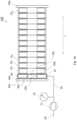
- FIG. 1A is a schematic view of a battery system or battery module 100 according to a first embodiment of the invention.
- the end plates 40a, 40b are part of the carrier framework or pack frame of the battery system or battery module 100. Thus, the end plates 40a, 40b provide fixation and restraint to both outer sides of the stack.
- the fluid spring 30 is positioned on one side of the stack of cells. More specifically, the fluid spring 30 is positioned between one of the end plates (in the example of Fig. 1 : the first end plate 40a) and cell 10 1 most adjacent to that end plate 40a.
- the first end plate bends due to the force / pressure exerted to it from the most adjacent cell 10 1 , the bending is compensated by the flexible fluid spring 30, as the flexible fluid spring 30 changes its shape accordingly. Therefore, the pressure provided onto the surface of the cells (and in particular to the first cell 10 1 ) is still uniform.
- the fluid in the bellows or bag of the fluid spring 30 is in fluid communication with a fluid pressure adjusting means 12 that may comprise a vacuum pump and a valve.
- the fluid pressure adjusting means 12 has a second connection 18 to a reservoir (not shown) for the working media, i. e. the fluid.
- the connection 18 is simply an outlet to the ambient atmosphere.
- a pressure sensor 14 may be arranged at a branch-off of the conduit 16 to measure the fluid pressure in the fluid spring 30.
- the pressures sensor 14 and the fluid pressure adjusting means 12 may each be connected (electrically or wirelessly) with a control unit (not shown) such that the control unit may receive signals from the pressure sensor 14 encoding the measured pressure and may transmit signals to the fluid pressure adjusting means 12 to control the fluid pressure.
- the control unit may be integrated in the BMU or BMS of the battery pack comprising the battery system100 shown in Fig. 1 .
- the bellows or bag of fluid spring 30 is made of or at least comprises an outer wall 32 suitable for being filled with fluid.
- the outer wall 32 embeds one or more cavities 36a, 36b, 36c suitable for the ingestion of fluid.
- the outer wall may be formed of an elastic material such that the bellows or bag itself forms an elastic device.
- one or more elastic support elements 34a, 34b may be formed inside the bellows or bag of fluid spring 30.
- the elastic support elements 34a, 34b may be made of the same material as the outer wall 32, or the elastic support elements 34a, 34b may be made of a material different from the material of the outer wall 32. In the latter case, the elasticity (i. e., the Young's modulus) of the material of the outer wall 32 may be different from the elasticity of the elastic support elements 34a, 34b.
- the one or more elastic support elements 34a, 34b may be bar-shaped (the bars each having a longitudinal center axis directed in the z-direction) and are arranged inside the bellows or bag of the fluid spring 30 such that only one single cavity is formed inside the outer wall 32, in this case, only the cross-sectional cut through this cavity is interrupted into several cavities 36a, 36b, 36c as shown in Fig. 1A , which are however, connected to each other in front of and behind the plane of the figure.
- the elastic support elements may be wall-shaped, such that the bellows of bag of the fluid spring 30 is divided in several cavities. In any case, each of the one or more cavities formed within the bellow or bag of fluid spring 30 must be in fluid connection with the fluid pressure adjusting means 12 (and the pressure sensor 14).
- a control unit 90 may be provided as shown in Fig. 1B .
- the control unit may be integrated in the battery management unit (BMU) of the battery system.
- the control unit 90 may be connected to the fluid pressure adjusting means 12 for controlling the pressure (underpressure) in the fluid spring 30 via a signal connection line 92.
- the signal from the control unit 90 to the fluid pressure adjusting means 12 for controlling the pressure may be transferred wirelessly.
- the control unit 90 is further connected to the pressure sensor 14 via a further signal connection line 94.
- the signal from the pressure sensor 14 to the control unit 90 may be transferred wirelessly.
- At least one safety check sensor 60 may be provided.
- the at least one safety check sensor 60 may be part of the battery system 100 or the safety check sensor(s) 60 may be arranged externally (as shown in Fig. 1B and indicated by the dashed box).
- the at least one safety check sensor 60 may be adapted to measure any physical / technical variable or entity, which may be used to evaluate the safety of the situation.
- the safety check sensor 60 may comprise an acceleration sensor to detect, whether an abrupt (negative) acceleration occurs that may indicate a crash of a vehicle.
- the safety check sensor 60 may comprise a temperature sensor to monitor the temperature of the ambient air of the battery system.
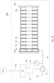
- FIG. 2 is a schematic view of a battery system or battery module 100 according to a second embodiment of the invention.
- a first fluid spring 30a is positioned on one outer side of the stack of cells, and a second fluid spring 30b is positioned on the opposite outer side of the stack of cells. More specifically, the first fluid spring 30a is positioned between a first end plate 40a and a first cell 10 1 being arranged, in the stack, most adjacent to the first end plate 40a, and the second fluid spring 30b is positioned between the second end plate 40b and a last cell 10 N being arranged, in the stack, most adjacent to the second end plate 40b.
- the fluid in the bellows or bag of the first fluid spring 30a is in fluid communication, via a first conduit 16a, with a first fluid pressure adjusting means 12a that may comprise a vacuum pump and a valve.
- the first fluid pressure adjusting means 12a has a second connection 18a to a (external) reservoir (not shown) for the working media, i. e., the fluid.
- a first pressure sensor 14a may be arranged at a branch-off of the first conduit 16a to measure the fluid pressure in the first fluid spring 30a.
- the two fluid springs 30a and 30b should preferably always be pressurized to the same pressure to prevent shifting of all cells to one side.
- the two fluid springs 30a, 30b are not connected and can thus controlled independently from each other.
- the same working media (fluid) is used for operating the first fluid spring 30a and the second fluid spring 30b.
- different working media may be used to operate the first fluid spring 30a and the second fluid spring 30b.
- the fluid springs 30a, 30b may be connected to each other, e. g., by the same conduit 16 as shown in the example of Fig. 3 ; see also the respective remarks as to the advantages of such an assembly as described below in the context of Fig. 3 .
- the first pressures sensor 14a and the first fluid pressure adjusting means 12a may each be connected (electrically or wirelessly) with a control unit (not shown) such that the control unit may receive signals from the pressure sensor 14a encoding the measured pressure within the first fluid spring 30a and may transmit signals to the first fluid pressure adjusting means 12a to control the fluid pressure.
- the second pressures sensor 14b and the second fluid pressure adjusting means 12b may each be connected (electrically or wirelessly) with the control unit (not shown).
- the control unit may be integrated in the BMU or BMS of the battery pack comprising the battery system 100 shown in Fig. 2 .
- the end plates 40a, 40b bend due to the force / pressure exerted to from the respective most adjacent cells 10 1 , 10 N , the bending of the end plates 40a, 40b is compensated by the fluid springs 30a and 30b, as the fluid springs 30a and 30b each change the shape accordingly. Therefore, the pressure on the surface of the cells (and in particular, on the first cell 10 1 and the last cell 10 N in the stack) is still uniform.
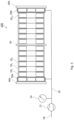
- Figure 3 is a schematic view of a battery system or battery module 100 according to a third embodiment of the invention.
- the embodiment shown in Fig. 3 largely corresponds to that described above in the context of the second embodiment depicted in Fig. 2 .
- the stack of the third embodiment comprises a positioning plate 50.
- the positioning plate 50 may be part of the carrier framework or frame pack and thus have a fixed position.
- the positioning plate 50 may also be arranged shiftable or moveable along the longitudinal axis of the stack.
- the positioning plate 50 may be positioned in the middle of the battery stack, i. e., in the example shown in Fig. 3 , between the 6 th and the 7 th cell, when numbering the cells starting from the left cell (the first cell 10 1 ) to the right cell (the last cell 10 12 ) within the stack.
- the positioning plate 50 may be positioned between the (N / 2)-th and the (N / 2 + 1)-th battery cell, and if N is an odd integer, positioning plate 50 may be positioned between the ((N - 1) / 2)-th and the ((N + 1) / 2)-th battery cell.
- the third embodiment with fluid springs 30a, 30b placed on both outer sides of the cell stack and a positioning plate 50 placed in the center of the cell stack as shown in Fig. 3 provides for an optimum pressure uniformity.
- the two fluid springs 30a, 30b should preferably be pressurized to the same pressure in order to negate any force / pressure on the positioning plate 50.
- the working media (fluid) of the two fluid springs 30a, 30b may communicate to equilibrate the pressure.
- the fluid springs 30a, 30b may be connected to each other by a conduit 16, which is also used to establish the fluid communication to the fluid pressure adjusting means 12.
- the fluid pressure adjusting means 12 may be, as already described in the context of the foregoing figures, a vacuum pump and a valve. As the two fluid springs 30a, 30b are connected by (branches of) the same conduit 16, it is sufficient in this case to use a single fluid pressure adjusting means 12 only.
- a pressure sensor 14 may be connected to conduit 16 to measure the pressure in both, the first and the second fluid spring 30a, 30b being, due to the assembly, in pressure equilibrium.
- the fluid pressure adjusting means 12 and the pressure sensor 14 may be connected (electrically or wirelessly) to a control unit to supervise the pressure and control the pressure as described in the context of the foregoing figures.
- a fluid spring 30 may also be placed in the middle of the stack to reduce the number of components.
- FIG. 4 illustrating a schematic view of a battery system or battery module according to a forth embodiment of the invention. Except for the position of the (single) fluid spring 30, the arrangement of the components of the battery module of Fig. 4 corresponds to the first embodiment shown in Fig. 1 . However, unlike to the first embodiment, the fluid spring 30 is placed in the center of the stack of battery cells. In the example shown in Fig. 4 , the fluid spring 30 is arranged between the 6 th and the 7 th cell, when numbering the cells starting from the left cell (the first cell 10 1 ) to the right cell (the last cell 10 12 ) within the stack.
- the fluid spring 30 may be positioned between the (N / 2)-th and the (N / 2 + 1)-th battery cell, and if N is an odd integer, fluid spring 30 may be positioned between the ((N - 1) / 2)-th and the ((N + 1) / 2)-th battery cell. Due to placing the fluid cell in the center of the stack, the equal distribution of pressure along the longitudinal axis of the stack is improved.
- FIG. 5 shows a schematic view of a battery system or battery module according to a fifth embodiment of the invention.
- the embodiment of the battery module 100 shown in Fig. 5 corresponds to the third embodiment of the battery module as shown in Fig. 3 except for the battery cells, which are 18 flat pouch cells 20 1 , 20 2 , ..., 20 18 in case of the module of Fig. 5 instead of 12 prismatic metal-can cells 10 1 , 10 2 , ..., 10 12 as shown in Fig. 3 .
- a positioning plate 50 is placed in the center of the stack of battery cells. The functioning of the positioning plate 50 corresponds to that already described in the context of Fig. 3 .
- the assembly of the fifth is altogether smaller in comparison with the third embodiment, although more battery cells are employed.
- the invention is especially suitable for long cell stacks (e. g. for stacks comprising 12 or more cells), so that only one or two fluid springs may be used for many cells. Of course, also more fluid springs may be employed, if required.
- Fluid springs apply a uniform pressure to the outer surface, in contrast to pressure plates (such as end plates) which may bend and apply non-uniform pressure under high load.
- pressure plates such as end plates
- the elastic device may exhibit a Young's modulus depending on the position on a plain perpendicular to the longitudinal axis of the stack (reference axis).
- the Young's modulus is chosen to be constant over that plain, i. e. the Young's modulus is independent from the position on this plain.
- the Young's modulus is chosen to be a function of the position of a plain perpendicular to the longitudinal axis.
- the Young's modulus may be chosen such that, when the fluid spring is arranged in the stack of cells, the cells having a center point with regard to the perpendicular plain, the Young's modulus has a maximum at the position of that center point (with regard to the perpendicular plain) and decreases with the distance to that center point.
- the Young's modulus may be rotationally symmetric around an axis through said center point and being directed in the direction of the longitudinal axis of the stack.
- the pressure may be adjusted on demand. For example, different pressures for charge and discharge of the cell, or different pressures depending on the state of charge (SoC) of the cell or different pressures depending on the state of health of the cell.
- SoC state of charge
- the fluid springs may be depressurized, to reduce the contact between the cells and to decrease the heat transfer at the interfaces between the cells.
- a decreased heat transfer has the advantage of impeding or slowing down the propagation of the thermal runaway from cell to cell.
- the control software of the battery pack which calculates the pressure set point can be easily updated, if field data shows the necessity adjust the algorithm for optimal cell pressurizing.
- the mechanical parts must not be changed if the pressure needs to be adjusted.
Landscapes
- Chemical & Material Sciences (AREA)
- Chemical Kinetics & Catalysis (AREA)
- Electrochemistry (AREA)
- General Chemical & Material Sciences (AREA)
- Engineering & Computer Science (AREA)
- Manufacturing & Machinery (AREA)
- Microelectronics & Electronic Packaging (AREA)
- Aviation & Aerospace Engineering (AREA)
- Secondary Cells (AREA)
- Battery Mounting, Suspending (AREA)
Priority Applications (5)
| Application Number | Priority Date | Filing Date | Title |
|---|---|---|---|
| EP20166297.0A EP3886202B1 (en) | 2020-03-27 | 2020-03-27 | Fluid spring pressurized battery stack |
| HUE20166297A HUE071136T2 (hu) | 2020-03-27 | 2020-03-27 | Fluidumrugóval nyomás alá helyezett akkumulátorköteg |
| PL20166297.0T PL3886202T3 (pl) | 2020-03-27 | 2020-03-27 | Stos akumulatorowy dociskany przez sprężyny płynowe |
| KR1020210036488A KR20210122112A (ko) | 2020-03-27 | 2021-03-22 | 전지 시스템 및 그 작동 방법 및 이를 포함하는 전지 팩 및 차량 |
| CN202110324284.XA CN113451666B (zh) | 2020-03-27 | 2021-03-26 | 电池系统及其操作方法以及包括其的电池组和车辆 |
Applications Claiming Priority (1)
| Application Number | Priority Date | Filing Date | Title |
|---|---|---|---|
| EP20166297.0A EP3886202B1 (en) | 2020-03-27 | 2020-03-27 | Fluid spring pressurized battery stack |
Publications (2)
| Publication Number | Publication Date |
|---|---|
| EP3886202A1 EP3886202A1 (en) | 2021-09-29 |
| EP3886202B1 true EP3886202B1 (en) | 2025-02-19 |
Family
ID=70056931
Family Applications (1)
| Application Number | Title | Priority Date | Filing Date |
|---|---|---|---|
| EP20166297.0A Active EP3886202B1 (en) | 2020-03-27 | 2020-03-27 | Fluid spring pressurized battery stack |
Country Status (4)
| Country | Link |
|---|---|
| EP (1) | EP3886202B1 (pl) |
| KR (1) | KR20210122112A (pl) |
| HU (1) | HUE071136T2 (pl) |
| PL (1) | PL3886202T3 (pl) |
Families Citing this family (25)
| Publication number | Priority date | Publication date | Assignee | Title |
|---|---|---|---|---|
| KR102754480B1 (ko) | 2019-05-08 | 2025-01-17 | 주식회사 엘지에너지솔루션 | 전고체전지의 제조방법 및 이를 이용하여 제조되는 전고체전지 |
| US11522212B2 (en) * | 2019-09-22 | 2022-12-06 | TeraWatt Technology Inc. | Layered pressure homogenizing soft medium for li-ion rechargeable batteries |
| KR102773568B1 (ko) * | 2020-07-22 | 2025-02-27 | 주식회사 엘지에너지솔루션 | 전지 모듈, 전지 모듈 시스템 및 전지 모듈을 포함하는 전지 팩 |
| KR102815957B1 (ko) * | 2020-11-10 | 2025-05-30 | 주식회사 엘지에너지솔루션 | 배터리 모듈의 하우징 용접부에 대한 피로파손 검증 장치 |
| DE102021117165A1 (de) | 2021-07-02 | 2023-01-05 | Volkswagen Aktiengesellschaft | Batteriemodul mit Druckbegrenzung, Traktionsbatterie und Kraftfahrzeug |
| WO2023049507A2 (en) | 2021-09-27 | 2023-03-30 | Quantumscape Battery, Inc. | Electrochemical stack and method of assembly thereof |
| DE102021004937A1 (de) * | 2021-10-01 | 2023-04-06 | Mercedes-Benz Group AG | Batteriemodulgehäuse für ein Batteriemodul, Batteriemodul sowie elektrischer Energiespeicher |
| DE102021132444A1 (de) | 2021-12-09 | 2023-06-15 | Bayerische Motoren Werke Aktiengesellschaft | Batteriezellenanordnung und fahrzeug mit einer batteriezellenanordnung |
| KR102706171B1 (ko) * | 2021-12-23 | 2024-09-12 | 비나텍주식회사 | 전기 에너지 저장셀간의 유격 발생을 방지하는 전기 에너지 저장셀 모듈 어셈블리 |
| CN116435699A (zh) * | 2022-01-04 | 2023-07-14 | 宁德时代新能源科技股份有限公司 | 一种电池及用电装置 |
| JP7726599B2 (ja) * | 2022-01-21 | 2025-08-20 | エルジー エナジー ソリューション リミテッド | 電池モジュールおよびその製造方法 |
| EP4386955A4 (en) * | 2022-02-18 | 2025-02-12 | LG Energy Solution, Ltd. | BATTERY PACK AND DEVICE THEREOF |
| CN114497870B (zh) | 2022-04-07 | 2022-11-08 | 嘉兴模度新能源有限公司 | 一种电池组均衡加压设备、电池组制备方法及电池模组 |
| US20230378580A1 (en) * | 2022-05-18 | 2023-11-23 | Solid Power Operating. Inc. | Battery pack system |
| KR102831003B1 (ko) * | 2022-11-02 | 2025-07-04 | 삼성에스디아이 주식회사 | 압력 유지 장치 및 이를 포함하는 배터리 시스템 |
| JP7729356B2 (ja) * | 2023-01-24 | 2025-08-26 | トヨタ自動車株式会社 | 電池システム |
| DE102023000535A1 (de) * | 2023-02-17 | 2024-08-22 | Mercedes-Benz Group AG | Verfahren zum Ansteuern einer Druckbeaufschlagungseinrichtung für ein Feststoffbatteriemodul sowie Batteriemanagementsystem |
| EP4459739A1 (en) * | 2023-05-04 | 2024-11-06 | Battery Sphere GmbH | Method for simulating real-life behavior of battery cells in a battery pack and a battery test device |
| KR102906907B1 (ko) * | 2023-06-22 | 2026-01-02 | 한국자동차연구원 | 배터리 시스템 및 그 작동 방법 |
| DE102023117577A1 (de) * | 2023-07-04 | 2025-01-09 | Bayerische Motoren Werke Aktiengesellschaft | Regelungseinheit für eine Batterieeinheit |
| KR102618649B1 (ko) | 2023-07-12 | 2023-12-27 | 한광현 | 배터리 셀 적층체에 압력을 가하는 장치를 포함하는배터리 모듈과 이를 구비한 배터리 팩 |
| WO2025074132A1 (ja) * | 2023-10-05 | 2025-04-10 | 日産自動車株式会社 | 全固体電池及び全固体電池の制御方法 |
| WO2025104462A1 (ja) * | 2023-11-13 | 2025-05-22 | 日産自動車株式会社 | 異常判定システム及び異常判定方法 |
| DE102023134706B3 (de) * | 2023-12-12 | 2025-04-24 | Dr. Ing. H.C. F. Porsche Aktiengesellschaft | Kraftfahrzeug mit einer Traktionsbatterie |
| IT202300027390A1 (it) * | 2023-12-20 | 2025-06-20 | Ferrari S P A | Modulo batteria per un pacco batteria veicolare |
Family Cites Families (3)
| Publication number | Priority date | Publication date | Assignee | Title |
|---|---|---|---|---|
| WO2015141631A1 (ja) * | 2014-03-17 | 2015-09-24 | 日産自動車株式会社 | バッテリセルの加圧装置 |
| WO2019017994A1 (en) * | 2017-07-21 | 2019-01-24 | Quantumscape Corporation | ACTIVE AND PASSIVE BATTERY PRESSURE MANAGEMENT |
| JP7022311B2 (ja) * | 2018-01-19 | 2022-02-18 | トヨタ自動車株式会社 | 電池モジュール |
-
2020
- 2020-03-27 EP EP20166297.0A patent/EP3886202B1/en active Active
- 2020-03-27 HU HUE20166297A patent/HUE071136T2/hu unknown
- 2020-03-27 PL PL20166297.0T patent/PL3886202T3/pl unknown
-
2021
- 2021-03-22 KR KR1020210036488A patent/KR20210122112A/ko active Pending
Also Published As
| Publication number | Publication date |
|---|---|
| KR20210122112A (ko) | 2021-10-08 |
| HUE071136T2 (hu) | 2025-08-28 |
| EP3886202A1 (en) | 2021-09-29 |
| PL3886202T3 (pl) | 2025-05-12 |
Similar Documents
| Publication | Publication Date | Title |
|---|---|---|
| EP3886202B1 (en) | Fluid spring pressurized battery stack | |
| US20240213579A1 (en) | Battery pack comprising frame profile having integral refrigerant circuit member | |
| US20130108897A1 (en) | Method For Thermal Management And Mitigation Of Thermal Propagation For Batteries Using A Graphene Coated Polymer Barrier Substrate | |
| KR102773568B1 (ko) | 전지 모듈, 전지 모듈 시스템 및 전지 모듈을 포함하는 전지 팩 | |
| CN111180622B (zh) | 电池组 | |
| EP4135108B1 (en) | Battery module, battery pack comprising same, and vehicle | |
| US20220045397A1 (en) | Battery pack | |
| US11855297B2 (en) | Battery unit, battery, and electric apparatus | |
| US11489224B2 (en) | Battery pack | |
| US20230136430A1 (en) | Battery including enclosure for battery cell groups | |
| JP2010165585A (ja) | 蓄電装置 | |
| EP2355201B1 (en) | Battery pack for an electric powertrain vehicle | |
| EP3772122B1 (en) | Battery module with a multifunctional end-plate | |
| EP3886203B1 (en) | A method for assembling a stack of prismatic battery cells, a stack of prismatic battery cells, a battery module and a vehicle including a battery pack comprising at least one battery module | |
| CN113451666B (zh) | 电池系统及其操作方法以及包括其的电池组和车辆 | |
| EP4542725A1 (en) | Battery system, cooler and method for monitoring a battery system | |
| US20250105377A1 (en) | Housing for a battery system, battery system, electric vehicle and method for detecting damage to the housing | |
| EP4513635B1 (en) | Battery module using side-pole battery cells and electrical connection of battery cell to battery cell | |
| US20250158195A1 (en) | Secondary battery module | |
| EP4478510A1 (en) | Secondary battery module and secondary battery pack comprising same | |
| US12341211B2 (en) | Lateral battery bracket comprising two semi products | |
| EP4525131A1 (en) | Battery system and method for monitoring a battery system | |
| EP4266455A1 (en) | Battery module having a housing with coolant jackets | |
| EP4632900A1 (en) | Battery system with improved end spacer | |
| EP4187701A1 (en) | Lateral battery bracket comprising two semi products |
Legal Events
| Date | Code | Title | Description |
|---|---|---|---|
| PUAI | Public reference made under article 153(3) epc to a published international application that has entered the european phase |
Free format text: ORIGINAL CODE: 0009012 |
|
| STAA | Information on the status of an ep patent application or granted ep patent |
Free format text: STATUS: REQUEST FOR EXAMINATION WAS MADE |
|
| STAA | Information on the status of an ep patent application or granted ep patent |
Free format text: STATUS: EXAMINATION IS IN PROGRESS |
|
| 17P | Request for examination filed |
Effective date: 20210527 |
|
| AK | Designated contracting states |
Kind code of ref document: A1 Designated state(s): AL AT BE BG CH CY CZ DE DK EE ES FI FR GB GR HR HU IE IS IT LI LT LU LV MC MK MT NL NO PL PT RO RS SE SI SK SM TR |
|
| 17Q | First examination report despatched |
Effective date: 20210906 |
|
| REG | Reference to a national code |
Ref country code: DE Ref legal event code: R079 Free format text: PREVIOUS MAIN CLASS: H01M0002100000 Ipc: H01M0010040000 Ref document number: 602020046193 Country of ref document: DE |
|
| RIC1 | Information provided on ipc code assigned before grant |
Ipc: H01M 10/48 20060101ALI20240904BHEP Ipc: H01M 10/42 20060101ALI20240904BHEP Ipc: H01M 10/04 20060101AFI20240904BHEP |
|
| GRAP | Despatch of communication of intention to grant a patent |
Free format text: ORIGINAL CODE: EPIDOSNIGR1 |
|
| STAA | Information on the status of an ep patent application or granted ep patent |
Free format text: STATUS: GRANT OF PATENT IS INTENDED |
|
| INTG | Intention to grant announced |
Effective date: 20241022 |
|
| GRAS | Grant fee paid |
Free format text: ORIGINAL CODE: EPIDOSNIGR3 |
|
| GRAA | (expected) grant |
Free format text: ORIGINAL CODE: 0009210 |
|
| STAA | Information on the status of an ep patent application or granted ep patent |
Free format text: STATUS: THE PATENT HAS BEEN GRANTED |
|
| AK | Designated contracting states |
Kind code of ref document: B1 Designated state(s): AL AT BE BG CH CY CZ DE DK EE ES FI FR GB GR HR HU IE IS IT LI LT LU LV MC MK MT NL NO PL PT RO RS SE SI SK SM TR |
|
| REG | Reference to a national code |
Ref country code: GB Ref legal event code: FG4D |
|
| REG | Reference to a national code |
Ref country code: CH Ref legal event code: EP |
|
| REG | Reference to a national code |
Ref country code: IE Ref legal event code: FG4D |
|
| REG | Reference to a national code |
Ref country code: DE Ref legal event code: R096 Ref document number: 602020046193 Country of ref document: DE |
|
| PGFP | Annual fee paid to national office [announced via postgrant information from national office to epo] |
Ref country code: AT Payment date: 20250409 Year of fee payment: 6 |
|
| REG | Reference to a national code |
Ref country code: SE Ref legal event code: TRGR |
|
| REG | Reference to a national code |
Ref country code: NL Ref legal event code: MP Effective date: 20250219 |
|
| PG25 | Lapsed in a contracting state [announced via postgrant information from national office to epo] |
Ref country code: RS Free format text: LAPSE BECAUSE OF FAILURE TO SUBMIT A TRANSLATION OF THE DESCRIPTION OR TO PAY THE FEE WITHIN THE PRESCRIBED TIME-LIMIT Effective date: 20250519 |
|
| PG25 | Lapsed in a contracting state [announced via postgrant information from national office to epo] |
Ref country code: FI Free format text: LAPSE BECAUSE OF FAILURE TO SUBMIT A TRANSLATION OF THE DESCRIPTION OR TO PAY THE FEE WITHIN THE PRESCRIBED TIME-LIMIT Effective date: 20250219 |
|
| PGFP | Annual fee paid to national office [announced via postgrant information from national office to epo] |
Ref country code: PL Payment date: 20250414 Year of fee payment: 6 Ref country code: DE Payment date: 20250402 Year of fee payment: 6 |
|
| PG25 | Lapsed in a contracting state [announced via postgrant information from national office to epo] |
Ref country code: ES Free format text: LAPSE BECAUSE OF FAILURE TO SUBMIT A TRANSLATION OF THE DESCRIPTION OR TO PAY THE FEE WITHIN THE PRESCRIBED TIME-LIMIT Effective date: 20250219 |
|
| PGFP | Annual fee paid to national office [announced via postgrant information from national office to epo] |
Ref country code: GB Payment date: 20250401 Year of fee payment: 6 |
|
| REG | Reference to a national code |
Ref country code: LT Ref legal event code: MG9D |
|
| PG25 | Lapsed in a contracting state [announced via postgrant information from national office to epo] |
Ref country code: IS Free format text: LAPSE BECAUSE OF FAILURE TO SUBMIT A TRANSLATION OF THE DESCRIPTION OR TO PAY THE FEE WITHIN THE PRESCRIBED TIME-LIMIT Effective date: 20250619 Ref country code: NO Free format text: LAPSE BECAUSE OF FAILURE TO SUBMIT A TRANSLATION OF THE DESCRIPTION OR TO PAY THE FEE WITHIN THE PRESCRIBED TIME-LIMIT Effective date: 20250519 |
|
| PGFP | Annual fee paid to national office [announced via postgrant information from national office to epo] |
Ref country code: HU Payment date: 20250429 Year of fee payment: 6 |
|
| PG25 | Lapsed in a contracting state [announced via postgrant information from national office to epo] |
Ref country code: NL Free format text: LAPSE BECAUSE OF FAILURE TO SUBMIT A TRANSLATION OF THE DESCRIPTION OR TO PAY THE FEE WITHIN THE PRESCRIBED TIME-LIMIT Effective date: 20250219 |
|
| PG25 | Lapsed in a contracting state [announced via postgrant information from national office to epo] |
Ref country code: HR Free format text: LAPSE BECAUSE OF FAILURE TO SUBMIT A TRANSLATION OF THE DESCRIPTION OR TO PAY THE FEE WITHIN THE PRESCRIBED TIME-LIMIT Effective date: 20250219 |
|
| PG25 | Lapsed in a contracting state [announced via postgrant information from national office to epo] |
Ref country code: PT Free format text: LAPSE BECAUSE OF FAILURE TO SUBMIT A TRANSLATION OF THE DESCRIPTION OR TO PAY THE FEE WITHIN THE PRESCRIBED TIME-LIMIT Effective date: 20250620 Ref country code: LV Free format text: LAPSE BECAUSE OF FAILURE TO SUBMIT A TRANSLATION OF THE DESCRIPTION OR TO PAY THE FEE WITHIN THE PRESCRIBED TIME-LIMIT Effective date: 20250219 |
|
| PGFP | Annual fee paid to national office [announced via postgrant information from national office to epo] |
Ref country code: FR Payment date: 20250423 Year of fee payment: 6 |
|
| PG25 | Lapsed in a contracting state [announced via postgrant information from national office to epo] |
Ref country code: GR Free format text: LAPSE BECAUSE OF FAILURE TO SUBMIT A TRANSLATION OF THE DESCRIPTION OR TO PAY THE FEE WITHIN THE PRESCRIBED TIME-LIMIT Effective date: 20250520 Ref country code: BG Free format text: LAPSE BECAUSE OF FAILURE TO SUBMIT A TRANSLATION OF THE DESCRIPTION OR TO PAY THE FEE WITHIN THE PRESCRIBED TIME-LIMIT Effective date: 20250219 |
|
| PGFP | Annual fee paid to national office [announced via postgrant information from national office to epo] |
Ref country code: SE Payment date: 20250411 Year of fee payment: 6 |
|
| REG | Reference to a national code |
Ref country code: HU Ref legal event code: AG4A Ref document number: E071136 Country of ref document: HU |
|
| PG25 | Lapsed in a contracting state [announced via postgrant information from national office to epo] |
Ref country code: SM Free format text: LAPSE BECAUSE OF FAILURE TO SUBMIT A TRANSLATION OF THE DESCRIPTION OR TO PAY THE FEE WITHIN THE PRESCRIBED TIME-LIMIT Effective date: 20250219 |
|
| PG25 | Lapsed in a contracting state [announced via postgrant information from national office to epo] |
Ref country code: DK Free format text: LAPSE BECAUSE OF FAILURE TO SUBMIT A TRANSLATION OF THE DESCRIPTION OR TO PAY THE FEE WITHIN THE PRESCRIBED TIME-LIMIT Effective date: 20250219 |
|
| PG25 | Lapsed in a contracting state [announced via postgrant information from national office to epo] |
Ref country code: IT Free format text: LAPSE BECAUSE OF FAILURE TO SUBMIT A TRANSLATION OF THE DESCRIPTION OR TO PAY THE FEE WITHIN THE PRESCRIBED TIME-LIMIT Effective date: 20250219 |
|
| PG25 | Lapsed in a contracting state [announced via postgrant information from national office to epo] |
Ref country code: CZ Free format text: LAPSE BECAUSE OF FAILURE TO SUBMIT A TRANSLATION OF THE DESCRIPTION OR TO PAY THE FEE WITHIN THE PRESCRIBED TIME-LIMIT Effective date: 20250219 Ref country code: EE Free format text: LAPSE BECAUSE OF FAILURE TO SUBMIT A TRANSLATION OF THE DESCRIPTION OR TO PAY THE FEE WITHIN THE PRESCRIBED TIME-LIMIT Effective date: 20250219 |
|
| PG25 | Lapsed in a contracting state [announced via postgrant information from national office to epo] |
Ref country code: RO Free format text: LAPSE BECAUSE OF FAILURE TO SUBMIT A TRANSLATION OF THE DESCRIPTION OR TO PAY THE FEE WITHIN THE PRESCRIBED TIME-LIMIT Effective date: 20250219 |
|
| REG | Reference to a national code |
Ref country code: CH Ref legal event code: H13 Free format text: ST27 STATUS EVENT CODE: U-0-0-H10-H13 (AS PROVIDED BY THE NATIONAL OFFICE) Effective date: 20251023 |
|
| PG25 | Lapsed in a contracting state [announced via postgrant information from national office to epo] |
Ref country code: SK Free format text: LAPSE BECAUSE OF FAILURE TO SUBMIT A TRANSLATION OF THE DESCRIPTION OR TO PAY THE FEE WITHIN THE PRESCRIBED TIME-LIMIT Effective date: 20250219 |
|
| PG25 | Lapsed in a contracting state [announced via postgrant information from national office to epo] |
Ref country code: LU Free format text: LAPSE BECAUSE OF NON-PAYMENT OF DUE FEES Effective date: 20250327 |
|
| REG | Reference to a national code |
Ref country code: DE Ref legal event code: R097 Ref document number: 602020046193 Country of ref document: DE |
|
| REG | Reference to a national code |
Ref country code: BE Ref legal event code: MM Effective date: 20250331 |
|
| PG25 | Lapsed in a contracting state [announced via postgrant information from national office to epo] |
Ref country code: MC Free format text: LAPSE BECAUSE OF FAILURE TO SUBMIT A TRANSLATION OF THE DESCRIPTION OR TO PAY THE FEE WITHIN THE PRESCRIBED TIME-LIMIT Effective date: 20250219 |
|
| PLBE | No opposition filed within time limit |
Free format text: ORIGINAL CODE: 0009261 |
|
| STAA | Information on the status of an ep patent application or granted ep patent |
Free format text: STATUS: NO OPPOSITION FILED WITHIN TIME LIMIT |
|
| PG25 | Lapsed in a contracting state [announced via postgrant information from national office to epo] |
Ref country code: BE Free format text: LAPSE BECAUSE OF NON-PAYMENT OF DUE FEES Effective date: 20250331 |
|
| PG25 | Lapsed in a contracting state [announced via postgrant information from national office to epo] |
Ref country code: CH Free format text: LAPSE BECAUSE OF NON-PAYMENT OF DUE FEES Effective date: 20250331 |
|
| PG25 | Lapsed in a contracting state [announced via postgrant information from national office to epo] |
Ref country code: IE Free format text: LAPSE BECAUSE OF NON-PAYMENT OF DUE FEES Effective date: 20250327 |
|
| 26N | No opposition filed |
Effective date: 20251120 |