EP3885899B1 - Hierarchische steuergerätelogik mit inkrementellen aktualisierungen - Google Patents
Hierarchische steuergerätelogik mit inkrementellen aktualisierungen Download PDFInfo
- Publication number
- EP3885899B1 EP3885899B1 EP21161388.0A EP21161388A EP3885899B1 EP 3885899 B1 EP3885899 B1 EP 3885899B1 EP 21161388 A EP21161388 A EP 21161388A EP 3885899 B1 EP3885899 B1 EP 3885899B1
- Authority
- EP
- European Patent Office
- Prior art keywords
- controller
- sub
- function blocks
- programming tool
- updated
- Prior art date
- Legal status (The legal status is an assumption and is not a legal conclusion. Google has not performed a legal analysis and makes no representation as to the accuracy of the status listed.)
- Active
Links
Images



Classifications
-
- G—PHYSICS
- G05—CONTROLLING; REGULATING
- G05B—CONTROL OR REGULATING SYSTEMS IN GENERAL; FUNCTIONAL ELEMENTS OF SUCH SYSTEMS; MONITORING OR TESTING ARRANGEMENTS FOR SUCH SYSTEMS OR ELEMENTS
- G05B19/00—Program-control systems
- G05B19/02—Program-control systems electric
- G05B19/04—Program control other than numerical control, i.e. in sequence controllers or logic controllers
- G05B19/05—Programmable logic controllers, e.g. simulating logic interconnections of signals according to ladder diagrams or function charts
- G05B19/056—Programming the PLC
-
- G—PHYSICS
- G05—CONTROLLING; REGULATING
- G05B—CONTROL OR REGULATING SYSTEMS IN GENERAL; FUNCTIONAL ELEMENTS OF SUCH SYSTEMS; MONITORING OR TESTING ARRANGEMENTS FOR SUCH SYSTEMS OR ELEMENTS
- G05B19/00—Program-control systems
- G05B19/02—Program-control systems electric
- G05B19/04—Program control other than numerical control, i.e. in sequence controllers or logic controllers
- G05B19/042—Program control other than numerical control, i.e. in sequence controllers or logic controllers using digital processors
- G05B19/0426—Programming the control sequence
-
- G—PHYSICS
- G06—COMPUTING OR CALCULATING; COUNTING
- G06F—ELECTRIC DIGITAL DATA PROCESSING
- G06F11/00—Error detection; Error correction; Monitoring
- G06F11/07—Responding to the occurrence of a fault, e.g. fault tolerance
- G06F11/08—Error detection or correction by redundancy in data representation, e.g. by using checking codes
- G06F11/10—Adding special bits or symbols to the coded information, e.g. parity check, casting out 9's or 11's
- G06F11/1004—Adding special bits or symbols to the coded information, e.g. parity check, casting out 9's or 11's to protect a block of data words, e.g. CRC or checksum
-
- G—PHYSICS
- G06—COMPUTING OR CALCULATING; COUNTING
- G06F—ELECTRIC DIGITAL DATA PROCESSING
- G06F8/00—Arrangements for software engineering
- G06F8/40—Transformation of program code
- G06F8/41—Compilation
-
- G—PHYSICS
- G06—COMPUTING OR CALCULATING; COUNTING
- G06F—ELECTRIC DIGITAL DATA PROCESSING
- G06F8/00—Arrangements for software engineering
- G06F8/60—Software deployment
- G06F8/65—Updates
- G06F8/654—Updates using techniques specially adapted for alterable solid state memories, e.g. for EEPROM or flash memories
-
- G—PHYSICS
- G06—COMPUTING OR CALCULATING; COUNTING
- G06F—ELECTRIC DIGITAL DATA PROCESSING
- G06F8/00—Arrangements for software engineering
- G06F8/60—Software deployment
- G06F8/65—Updates
- G06F8/658—Incremental updates; Differential updates
-
- G—PHYSICS
- G05—CONTROLLING; REGULATING
- G05B—CONTROL OR REGULATING SYSTEMS IN GENERAL; FUNCTIONAL ELEMENTS OF SUCH SYSTEMS; MONITORING OR TESTING ARRANGEMENTS FOR SUCH SYSTEMS OR ELEMENTS
- G05B2219/00—Program-control systems
- G05B2219/10—Plc systems
- G05B2219/13—Plc programming
- G05B2219/13004—Programming the plc
-
- G—PHYSICS
- G05—CONTROLLING; REGULATING
- G05B—CONTROL OR REGULATING SYSTEMS IN GENERAL; FUNCTIONAL ELEMENTS OF SUCH SYSTEMS; MONITORING OR TESTING ARRANGEMENTS FOR SUCH SYSTEMS OR ELEMENTS
- G05B2219/00—Program-control systems
- G05B2219/20—Pc systems
- G05B2219/25—Pc structure of the system
- G05B2219/25011—Domotique, I-O bus, home automation, building automation
-
- G—PHYSICS
- G05—CONTROLLING; REGULATING
- G05B—CONTROL OR REGULATING SYSTEMS IN GENERAL; FUNCTIONAL ELEMENTS OF SUCH SYSTEMS; MONITORING OR TESTING ARRANGEMENTS FOR SUCH SYSTEMS OR ELEMENTS
- G05B2219/00—Program-control systems
- G05B2219/20—Pc systems
- G05B2219/26—Pc applications
- G05B2219/2614—HVAC, heating, ventillation, climate control
Definitions
- the present disclosure relates generally to configuring a controller. More particularly, the present disclosure relates to methods and systems for configuring a controller that utilizes hierarchal controller logic.
- a controller may be used to control operations of a variety of different components.
- Programming tools may be used to program or otherwise configure a controller for controlling a particular function or feature of a piece of equipment.
- the programming tool typically needs to compile the entire control program and download the entire compiled control program to the controller. This can be time-consuming, particularly over a low bandwidth communication channel.
- a method of programming a controller that is configured to control operation of a building component includes using a programming tool to build controller logic that utilizes sub-structures organized within a hierarchal tree, and then downloading the controller logic including the sub-structures organized within the hierarchal tree to the controller.
- the controller is operated using the downloaded controller logic such that the controller controls operation of the building component.
- the programming tool is subsequently used to change one or more of the sub-structures, such as editing one or more of the sub-structures, adding one or more sub-structures, deleting one or more of the sub-structures and/or otherwise changing the controller logic.
- the one or more updated sub-structures are downloaded to the controller while not downloading one or more of the other sub-structures that were not updated.
- the method includes continuing to control operation of the building component using the controller logic that now includes the one or more updated sub-structures.
- the controller that is configured to control operation of a building component includes a memory that is configured to store a modular controller logic that has a plurality of sub-structures that are arranged in a hierarchal tree.
- a processor is operatively coupled to the memory and is configured to execute the modular controller logic in order to control operation of the building component.
- a communications block is operably coupled to the processor and is configured to communicate with a programming tool that is used to create and/or edit the sub-structures within the modular controller logic.
- the modular controller logic is initially created using the programming tool and is downloaded to the controller via the communications block for execution. Subsequent updates to one or more of the sub-structures are subsequently downloaded to the controller via the communications block once updated via the programming tool, while sub-structures that were not updated are not downloaded.
- a method of testing a modular controller logic within a programming tool includes a plurality of sub-structures that are organized into a hierarchal tree.
- the modular controller logic is present within a controller and is synchronized within the programming tool, and the programming tool is configured to test execute the modular control logic directly within the programming tool.
- the modular control logic is built within the programming tool, and is test executed within the programming tool.
- One or more sub-structures within the modular control logic are updated to provide an updated modular control logic.
- the updated modular control logic is test executed within the programming tool.
- references in the specification to "an embodiment”, “some embodiments”, “other embodiments”, etc., indicate that the embodiment described may include a particular feature, structure, or characteristic, but every embodiment may not necessarily include the particular feature, structure, or characteristic. Moreover, such phrases are not necessarily referring to the same embodiment. Further, when a particular feature, structure, or characteristic is described in connection with an embodiment, it is contemplated that the feature, structure, or characteristic is described in connection with an embodiment, it is contemplated that the feature, structure, or characteristic may be applied to other embodiments whether or not explicitly described unless clearly stated to the contrary.
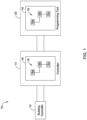
- FIG. 1 is a schematic block diagram of an illustrative system 10.
- the illustrative system 10 includes a building component 12.
- the building component 12 may generically represent any of a number of different components that may be found within any of a variety of building systems. Illustrative but non-limiting examples of building systems include Heating, Ventilating and Air Conditioning (HVAC) systems, security systems, lighting systems, fire systems, and others.
- HVAC Heating, Ventilating and Air Conditioning
- HVAC Heating, Ventilating and Air Conditioning
- the illustrative system 10 includes a controller 14. It will be appreciated that the controller 14 may be designed or programmed to control an operation of the building component 12. In some cases, the controller 14 may be a Direct Digital Control (DDC) controller, although this is not required in all cases. In some cases, the controller 14 may operate in accordance with a hierarchal control logic in which a number of sub-structures are arranged within a hierarchal structure. The controller 14 may work through each of the sub-structures within the hierarchal structure, in an order dictated by how each of the sub-structures are linked together. In Figure 1 , the controller 14 may be seen as including a hierarchal control logic 16.
- DDC Direct Digital Control
- the hierarchal control logic 16 is simplified and includes several sub-structures 18 that are individually labeled as 18a, 18b, 18c. It will be appreciated that this is highly simplified, as the hierarchal control logic 16 may have any number of sub-structures, including but not limited to folders, function blocks and links between folders and/or function blocks. Illustrative but non-limiting examples of folders, function blocks and links therebetween may be found in US 8,738,793 and US 8,983,632 , both of which are incorporated by reference herein in their entirety.
- the illustrative system 10 includes a programming tool 20 that can be used to initially program the controller 14. For example, a user may use the programming tool 20 to create the hierarchal control logic 16 and then subsequently download the hierarchal control logic 16 from the programming tool 20 to the controller 14. If desired, the user may use the programming tool 20 to make one or more edits, corrections, additions or deletions to the hierarchal control logic 16. In some cases, only the sub-structures 18 that are edited, added, deleted, moved or otherwise changed may be downloaded to the controller 14, while the other sub-structures 18 that are not changed in any manner or fashion, are not downloaded again to the controller 14. It will be appreciated that this reduces the communication time that would otherwise be needed to update the hierarchal control logic 16.
- the controller 14 may be configured to operate in accordance with each of the sub-structures 18 outlined within the hierarchal control logic 16 without having to separately compile each of the sub-structures individually, or compile the hierarchal control logic 16 as a whole.
- the controller 14 may include an engine that is configured to interpret the hierarchal control logic 16 and produce corresponding control signals and/or control commands for controlling one or more building components.
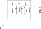
- FIG 2 is a schematic block diagram of an illustrative controller 22 that may be considered as an example of the controller 14 that is referenced with respect to Figure 1 .
- the illustrative controller 22 is configured to control operation of a building component (such as but not limited to the building component 12) and includes a memory 24 that is configured to store modular controller logic such as the hierarchal control logic 16 that includes a plurality of sub-structures (such as but not limited to the sub-structures 18) that are arranged in a hierarchal tree.
- the controller 22 may be configured to control operation of a Heating, Ventilating and Air Conditioning (HVAC) system component, a lighting system component, a water heater system component, a water softener system component, a sprinkler system component or a security system component.
- HVAC Heating, Ventilating and Air Conditioning
- the illustrative controller 22 includes a processor 26 that is operably coupled to the memory 24 and that is configured to execute the modular controller logic in order to control operation of the building component.
- a communications block 28 is operably coupled to the processor 26 and is configured to communicate with a programming tool (such as but not limited to the programming tool 20) that is used to create and/or edit the sub-structures within the modular controller logic.
- the modular controller logic may be initially created using the programming tool and may be downloaded to the controller 22 via the communications block 28 for execution. Subsequent updates to one or more of the sub-structures may be subsequently downloaded to the controller 22 via the communications block 28, while not downloading one or more of the sub-structures that were not updated.
- At least some of the sub-structures may individually include one or more of a link, a folder and a function block.
- Each of the sub-structures may, for example, include an address linking path that defines an address space and a breadcrumb number that defines a unique component within the address space. It will be appreciated that the address linking path and breadcrumb number, in combination, link each sub-structure to a particular location within the modular controller logic so that the controller 22 knows how and when to execute the instructions present within each of the sub-structures.
- FIG 3 is a schematic block diagram of an illustrative controller 30.
- the illustrative controller 30 may be considered as being an example of the controller 14 and/or the controller 22. In some instances, the controller 30 may include features and/or functionality ascribed to the controller 14 and/or the controller 22. Similarly, the controller 14 and/or the controller 22 may include features and/or functionality ascribed to the other, or may include features and/or functionality ascribed to the controller 30.
- the illustrative controller 30 is a DDC (Direct Digital Control) controller, but this is not required.
- the illustrative controller 30 includes a DDC Command Service block 32 and a Storage Manager 34.
- the controller 30 includes a Flash Memory block 36 and a Serial Flash Memory block 38.
- the Flash Memory block 36 may be used to store the modular control logic, while the Serial Flash Memory block 38 may be used to store other information, such as but not limited to data used for operating a user interface (not illustrated).
- the Flash Memory block 36 is in communication with a DDC Engine 40.
- the DDC Engine 40 may be configured to execute each of the sub-structures included in the modular control logic, which itself may be stored within the Flash Memory block 36.
- a DDC Runtime block 42 remains in communication with the DDC Engine 40.
- the modular control logic stored within the Flash Memory block 36 may be downloaded to a programming tool not previously used to create and/or edit the modular control logic.
- graphical information e.g. x,y display location of each of the function blocks as well as interconnect paths
- other information related to the modular control logic may be retrieved from the Serial Flash Memory block 38.
- the technician can connect his programming tool to any controller, at which time his programming tool may download the modular control logic from the Flash Memory block 36 and the graphical information (e.g. x,y location of each of the function blocks as well as interconnect paths) and/or other information related to the modular control logic from the Serial Flash Memory block 38 of the controller. His programming tool may use this downloaded information to re-create the programming tool environment that was previously used to program the controller. The technician can then make changes, and download those changes to the controller.
- the DDC Command Service Block 32 may accept Commands from a programming tool.
- the programming tool may issue Commands to the DDC Command Service Block 32 to make changes or updates to one or more of the sub-structures of the modular control logic stored in the Flash Memory block 36.
- Such Commands may be used to selectively download the sub-structures that were changed using the programming tool while not downloading the sub-structures that did not change.
- Attached hereto is an Appendix that includes a number of example Commands and corresponding Responses that may be carried out using a programming tool to create and/or edit a modular control logic in a controller as described herein.
- the DDC Command Service Block 32 of the controller may be used to interpret and implement the Commands.
- a few illustrative Commands contained in the Appendix include Create Child, Delete Child, Set Properties, Set Predecessor and Set Multiple Links. It will be appreciated that the Command to Create a Child may be used if there is a desire to insert an additional function block within an existing modular control logic hierarchy.
- the Command Delete Child is, of course, the opposite, and would be used to delete a child function block that was previously created.
- the Set Properties Command may be used, for example, if a user desired to change or add additional properties to one or more function blocks.
- the Command to Set Predecessor may be used to select or change an order of operation of the function blocks.
- the Set Multiple Links Command may be used to instruct how a number of function blocks are to be operably coupled, meaning setting which inputs are coupled to which outputs.
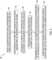
- Figure 4 is a flow diagram showing an illustrative method 50 of programing a controller (such as but not limited to the controller 14, the controller 22 and the controller 30) that is configured to control operation of a building component (such as but not limited to the building component 12).
- a programming tool may be used to build a controller logic that utilizes sub-structures that are organized within a hierarchal tree, as indicated at block 52.
- the controller logic including the sub-structures that are organized within the hierarchal tree, may be downloaded to the controller, as indicated at block 54.
- the sub-structures may include one or more folders, and at least some of the one or more folders may include one or more function blocks. In some cases, the sub-structures may include one or more links for logically linking one or more of the function blocks.
- the sub-structures may, for example, include an address linking path that defines an address space as well as a breadcrumb number that defines a unique position within the address space. Accordingly, the combination of the address linking path and the breadcrumb uniquely identifies each of the sub-structures and their position relative to each of the other sub-structures as well as the hierarchal tree in which each of the sub-structures are arranged and organized.
- the controller may be operated via the controller logic such that the controller controls operation of the building component, as indicated at block 56.
- the programming tool may subsequently be used to update one or more of the sub-structures, as indicated at block 58.
- the one or more updated sub-structures may be downloaded to the controller while not downloading one or more of the sub-structures that were not updated, as indicated at block 60. This may be accomplished using one or more of the Commands in the attached Appendix. Operation of the building component may continue using the controller logic that now includes the one or more updated sub-structures, as indicated at block 62.
- each of the sub-structures may include a calculated and stored Cyclic Redundancy Check (CRC) value and each updated sub-structure includes an updated calculated and stored CRC value.
- CRC Cyclic Redundancy Check
- the overall controller logic itself may have a CRC value that is a summation of each of the CRC values for each of the sub-structures.
- updated sub-structures are downloaded from the programming tool to the controller. This may be accomplished using one or more of the Commands contained in the attached Appendix.
- the programming tool may periodically be used to compare a current CRC value for each sub-structure to a stored CRC value for the same sub-structure to look for sub-structures that have been updated since a previous check. Any sub-structures that are thus found to have been updated in the programming tool since a previous check may be downloaded to the controller.
- each sub-structure within the programming tool may include a logical UPDATE flag, and updating a sub-structure includes setting the logical UPDATE flag for that sub-structure to true.
- the logical UPDATE flag may be checked for each sub-structure, and for each logical UPDATE flag set to true in the programming tool, the corresponding updated sub-structure may be downloaded to the controller. In some cases, downloading the one or more updated sub-structures to the controller occurs immediately after the programming tool is used to update the one or more updated sub-structures.
- Figure 5 is a flow diagram showing an illustrative method 70 of testing a modular controller logic within a programming tool, where the modular controller logic includes a plurality of sub-structures that are organized into a hierarchal tree.
- the modular controller logic is present within a controller and is synchronized within the programming tool such that the programming tool is configured to test execute the modular control logic directly within the programming tool.
- the modular control logic may be built within the programming tool, as indicated at block 72.
- the modular control logic may be test executed within the programming tool, as indicated at block 74.
- One or more of the sub-structures within the modular control logic may be updated to provide an updated modular control logic, as indicated at block 76.
- the updated modular control logic may be test executed, as indicated at block 78. In some cases, the updated modular control logic may be downloaded to the controller so that the controller can execute the updated modular control logic.
- FIG. 6 is a schematic block diagram showing an illustrative modular control logic 80.
- the illustrative modular control logic 80 includes a number of folders 82 that are organized within a hierarchal tree 84. Some of the folders 82 include one or more function blocks 86 contained therein. Each of the function blocks 86 may, for example, be OR function block, AND function block, a PID function block, among others. Each of the function blocks 86 include one or more inputs, shown as hollow carrots above each function block, and one or more outputs that are shown as solid carrots below each function block. In this particular example, a change is being made with respect to which output of one function block is being coupled with an input of another function block.
- Function block 86a can be seen as having an Output 0 and an Output 1.
- Function block 86b can be seen as having an Input 0 and an Input 1.
- the Output 1 of the function block 86a has an ORD, which may be considered as equivalent to an address linking path, of /2/1/4/1 while the function block 86b has an ORD of /2/3/2/5.
- a programming tool such as the programming tool 20 ( Figure 1 ) may for example display a modular control logic such as the illustrative modular control logic 80 shown in Figure 6 .
- a programming tool may have a display that is divided into a left panel and a right panel.
- the left panel for example, may display a hierarchal tree, with folders, such as that shown in Figure 6 .
- the right panel for example, may display a number of function blocks as shown in Figure 6 .
- the right panel may, for example, display a number of function blocks in greater detail, as shown in Figure 7 .
- Figure 7 is a screen capture of a portion of an illustrative but non-limiting wire screen 130.
- an actual wire screen 130 may be much larger, and include a large number of function blocks and accompanying links between the various inputs and outputs of each of the function blocks.
- the wire screen 130 includes an RHFLOAT floating output function block 132.
- the RHFLOAT floating output function block 132 displays various parameter values. In some cases, which parameter values are used and/or displayed may be user-programmed. In the example show, one of the displayed parameter values is an HOA parameter 134 and its accompanying value 136.
- the HOA parameter 134 represents a particular HOA (HAND-OFF-AUTO) switch that is associated with the RHFLOAT floating output function block 132.
- a HOA switch is a mechanically actuated switch that is actuatable between a HAND (H) setting which represents a manual "ON” setting, an OFF (O) setting which shuts off a particular output associated with that particular HOA switch, and an AUTO (A) setting which places the particular output in automatic control (e.g., to be controlled by a control algorithm of the controller).
- the RHFLOAT floating output function block 132 is associated with a floating motor.
- a floating motor is a motor that can be driven in a first direction (say, to open a damper) by applying voltage pulses to a first electrical contact, and can be driven in a second direction (say, to close the damper) by applying voltage pulses to a second electrical contact.
- the floating motor would of course also have a ground contact.
- the RHFLOAT floating output function block 132 can be seen as being operably coupled to an RHOPN1 function block 138 that controls whether an output DO-3 of the controller is energized and a RHCL01 function block 140 that controls whether an output DO-4 is energized.
- a PIN parameter 142 and associated value 144 as shown in the RHOPN1 function block 138 and a PIN parameter 146 and associated value 148 as shown in the RHOPN1 function block 138.
- the output DO-3 when energized, drives the floating motor in a first direction while the output DO-4, when energized, drives the floating motor in an opposing second direction.
- the OPEN parameter 150 and associated FALSE value 152 and the CLOSED parameter 154 and associated FALSE value 156 This is just an example wire screen of modular control logic for a controller.
Landscapes
- Engineering & Computer Science (AREA)
- General Engineering & Computer Science (AREA)
- Theoretical Computer Science (AREA)
- Software Systems (AREA)
- Physics & Mathematics (AREA)
- General Physics & Mathematics (AREA)
- Computer Security & Cryptography (AREA)
- Automation & Control Theory (AREA)
- Quality & Reliability (AREA)
- Stored Programmes (AREA)
- Programmable Controllers (AREA)
Claims (10)
- Verfahren zum Programmieren einer Steuerung (14), die einen Speicher zum Speichern einer Steuerungslogik und einen Prozessor beinhaltet, der zum Ausführen der in dem Speicher gespeicherten Steuerungslogik betriebsfähig mit dem Speicher gekoppelt ist, um einen Betrieb einer Gebäudekomponente (12) zu steuern, das Verfahren umfassend:Verwenden eines Programmiertools (20), um die Steuerungslogik aufzubauen, die innerhalb eines Hierarchiebaums organisierte Teilstrukturen benutzt, wobei die Teilstrukturen einen oder mehrere Ordner mit einem oder mehreren Funktionsblöcken innerhalb mindestens einiger des einen oder der mehreren Ordner und eine oder mehrere Verknüpfungen, die einen oder mehrere der Funktionsblöcke logisch verknüpfen, beinhalten;Herunterladen der Steuerungslogik in den Speicher der Steuerung, die die innerhalb des Hierarchiebaums organisierten Teilstrukturen beinhaltet, die den einen oder die mehreren Funktionsblöcke und die eine oder die mehreren Verknüpfungen, die einen oder mehrere der Funktionsblöcke logisch verknüpfen, beinhalten;Ausführen, durch den Prozessor, der in dem Speicher der Steuerung gespeicherten Steuerungslogik, um einen Betrieb der Gebäudekomponente zu steuern;anschließendes Verwenden des Programmiertools, um eine oder mehrere der Teilstrukturen zu aktualisieren, die einen oder mehrere der Funktionsblöcke und/oder eine oder mehrere Verknüpfungen, die einen oder mehrere der Funktionsblöcke der Steuerungslogik logisch verknüpfen, beinhalten, sodass eine aktualisierte Steuerungslogik entsteht;Markieren, durch das Programmiertool, der Funktionsblöcke und/oder der einen oder der mehreren Verknüpfungen der Steuerungslogik, die unter Verwendung des Programmiertools aktualisiert wurden;Herunterladen, durch das Programmiertool, des einen oder der mehreren markierten Funktionsblöcke und/oder der einen oder der mehreren markierten Verknüpfungen in den Speicher der Steuerung, jedoch nicht Herunterladen des einen oder der mehreren Funktionsblöcke und/oder der einen oder der mehreren Verknüpfungen, die nicht von dem Programmiertool markiert wurden, wobei der eine oder die mehreren der Funktionsblöcke und/oder die eine oder die mehreren Verknüpfungen, die nicht von dem Programmiertool markiert und in dem Speicher gespeichert sind, in Kombination mit dem einen oder den mehreren markierten Funktionsblöcken und/oder der einen oder den mehreren markierten Verknüpfungen, die in den Speicher der Steuerung heruntergeladen sind, die aktualisierte Steuerungslogik in dem Speicher der Steuerung darstellen; undAusführen, durch den Prozessor der Steuerung, der in dem Speicher der Steuerung gespeicherten aktualisierten Steuerungslogik, um einen Betrieb der Gebäudekomponente zu steuern.
- Verfahren nach Anspruch 1, wobei jede der Teilstrukturen ferner einen Adressverknüpfungspfad beinhaltet, der einen Adressraum in dem Speicher der Steuerung definiert, und optional jede der Teilstrukturen eine Brotkrümel-Nummer beinhaltet, die eine eindeutige Komponente innerhalb des Adressraums definiert.
- Verfahren nach Anspruch 1 oder 2, wobei jede Teilstruktur einen berechneten und gespeicherten zyklischen Redundanzprüfungs, "CRC", -Wert beinhaltet und jede aktualisierte Teilstruktur einen aktualisierten berechneten und gespeicherten CRC-Wert beinhaltet.
- Verfahren nach Anspruch 3, wobei die Steuerungslogik einen CRC-Wert aufweist, der eine Summierung jedes der CRC-Werte für jede der Teilstrukturen ist.
- Verfahren nach Anspruch 3, ferner umfassend periodisches Verwenden des Programmiertools, um einen aktuellen CRC-Wert für jede Teilstruktur mit einem gespeicherten CRC-Wert für dieselbe Teilstruktur zu vergleichen, um nach Teilstrukturen zu suchen, die seit einer vorherigen Prüfung aktualisiert wurden.
- Verfahren nach einem der Ansprüche 1 bis 5, ferner umfassend Herunterladen auf die Steuerung von allen Teilstrukturen, für die ermittelt wurde, dass sie seit einem vorherigen Herunterladen aktualisiert wurden.
- Verfahren nach einem der Ansprüche 1 bis 6, wobei jede Teilstruktur einen Adressverknüpfungspfad, der einen Adressraum definiert, eine Brotkrümel-Nummer, die eine eindeutige Komponente innerhalb des Adressraums definiert, und einen zyklischen Redundanzprüfungs, "CRC", -Wert beinhaltet.
- Steuerung, die dazu konfiguriert ist, einen Betrieb einer Gebäudekomponente zu steuern, die Steuerung umfassend:einen Speicher, der dazu konfiguriert ist, eine modulare Steuerungslogik zu speichern, wobei die modulare Steuerungslogik eine Vielzahl von Teilstrukturen umfasst, die in einem Hierarchiebaum angeordnet sind, wobei die Teilstrukturen einen oder mehrere Ordner mit einem oder mehreren Funktionsblöcken innerhalb mindestens einiger des einen oder der mehreren Ordner und eine oder mehrere Verknüpfungen zum logischen Verknüpfen von einem oder mehreren der Funktionsblöcke beinhalten;einen Prozessor, der betriebsfähig mit dem Speicher gekoppelt und dazu konfiguriert ist, die in dem Speicher gespeicherte modulare Steuerungslogik auszuführen, um einen Betrieb der Gebäudekomponente zu steuern;einen Kommunikationsblock, der betriebsfähig mit dem Prozessor gekoppelt ist, wobei der Kommunikationsblock dazu konfiguriert ist, mit einem Programmiertool zu kommunizieren, das dazu verwendet wird, die Teilstrukturen innerhalb der modularen Steuerungslogik, die in dem Speicher gespeichert ist, zu erstellen und/oder zu bearbeiten;wobei die modulare Steuerungslogik anfangs unter Verwendung der Programmiertools erstellt wird und in den Speicher der Steuerung über den Kommunikationsblock zur Ausführung heruntergeladen wird, wobei jede der Teilstrukturen der modularen Steuerungslogik einen Adressverknüpfungspfad, der einen Adressraum in dem Speicher der Steuerung definiert, und eine Brotkrümel-Nummer, die eine eindeutige Komponente innerhalb des Adressraums des Speichers der Steuerung definiert, beinhaltet;wobei das Programmiertool anschließend dazu verwendet wird, eine oder mehrere der Teilstrukturen zu aktualisieren, die einen oder mehrere der Funktionsblöcke und/oder eine oder mehrere Verknüpfungen, die einen oder mehrere der Funktionsblöcke der Steuerungslogik logisch verknüpfen, beinhaltet, sodass eine aktualisierte Steuerungslogik entsteht;wobei das Programmiertool die Funktionsblöcke und/oder die eine oder die mehreren Verknüpfungen der Steuerungslogik, die unter Verwendung des Programmiertools aktualisiert wurden, markiert; anschließende Aktualisierungen an einer oder mehrerer der Teilstrukturen anschließend in den Speicher der Steuerung über den Kommunikationsblock heruntergeladen werden, sobald sie über das Programmiertool aktualisiert wurden, jedoch nicht ein oder mehrere Funktionsblöcke und/oder die eine oder die mehreren Verknüpfungen in den Speicher der Steuerung heruntergeladen werden, die nicht von dem Programmiertool markiert wurden, wobei der eine oder die mehreren der Funktionsblöcke und/oder die eine oder die mehreren Verknüpfungen, die nicht von dem Programmiertool markiert und in dem Speicher gespeichert sind, in Kombination mit dem einen oder den mehreren markierten Funktionsblöcken und/oder der einen oder den mehreren markierten Verknüpfungen, die in den Speicher der Steuerung heruntergeladen sind, die aktualisierte Steuerungslogik in dem Speicher der Steuerung darstellen; undwobei der Prozessor die in dem Speicher der Steuerung gespeicherte aktualisierte modulare Steuerungslogik ausführt, um einen Betrieb der Gebäudekomponente zu steuern.
- Steuerung nach Anspruch 8, wobei die Gebäudekomponente eine aus einer Heizungs-, Lüftungs- und Klimatechnik, "HVAC", -Systemkomponente, einer Beleuchtungssystemkomponente, einer Wasserheizsystemkomponente, einer Wasserenthärtersystemkomponente, einer Sprinklersystemkomponente oder einer Sicherheitssystemkomponente umfasst.
- Verfahren zum Testen einer modularen Steuerungslogik innerhalb eines Programmiertools, wobei die modulare Steuerungslogik eine Vielzahl von Teilstrukturen beinhaltet, die in einem Hierarchiebaum organisiert sind, wobei die Teilstrukturen einen oder mehrere Ordner mit einem oder mehreren Funktionsblöcken innerhalb mindestens einiger des einen oder der mehreren Ordner und eine oder mehrere Verknüpfungen zum logischen Verknüpfen von einem oder mehreren der Funktionsblöcke beinhalten, wobei die modulare Steuerungslogik innerhalb einer Steuerung wie in Anspruch 8 offenbart vorliegt und innerhalb des Programmiertools synchronisiert ist, wobei das Programmiertool dazu konfiguriert ist, die modulare Steuerungslogik direkt innerhalb des Programmiertools testweise auszuführen, das Verfahren umfassend:Aktualisieren von einer oder mehreren Teilstrukturen innerhalb der modularen Steuerungslogik, um eine aktualisierte modulare Steuerungslogik bereitzustellen, wobei das Programmiertool dazu verwendet wird, eine oder mehrere der Teilstrukturen zu aktualisieren, die einen oder mehrere der Funktionsblöcke und/oder eine oder mehrere Verknüpfungen, die einen oder mehrere der Funktionsblöcke der Steuerungslogik logisch verknüpfen, beinhaltet, sodass eine aktualisierte Steuerungslogik entsteht;Markieren, durch das Programmiertool, der Funktionsblöcke und/oder der einen oder der mehreren Verknüpfungen der Steuerungslogik, die unter Verwendung des Programmiertools aktualisiert wurden;nach Aktualisieren des einen oder der mehreren der Funktionsblöcke und/oder einer oder mehrerer Verknüpfungen, die einen oder mehrere der Funktionsblöcke logisch verknüpfen, testweises Ausführen der aktualisierten modularen Steuerungslogik unter Verwendung des Programmiertools;nach testweisem Ausführen der aktualisierten modularen Steuerungslogik unter Verwendung des Programmiertools, Herunterladen des einen oder der mehreren aktualisierten Funktionsblöcke und/oder einer oder mehrerer aktualisierter Verknüpfungen auf die Steuerung, jedoch nicht Herunterladen eines oder mehrerer der Funktionsblöcke und/oder einer oder mehrerer Verknüpfungen, die nicht von dem Programmiertool markiert wurden, wobei der eine oder die mehreren der Funktionsblöcke und/oder die eine oder die mehreren Verknüpfungen, die nicht von dem Programmiertool markiert und in dem Speicher gespeichert sind, in Kombination mit dem einen oder den mehreren markierten Funktionsblöcken und/oder der einen oder den mehreren markierten Verknüpfungen, die in den Speicher der Steuerung heruntergeladen sind, die aktualisierte Steuerungslogik in dem Speicher der Steuerung darstellen; undSteuern, unter Verwendung der Steuerung, eines Betriebs einer Gebäudekomponente unter Verwendung der aktualisierten modularen Steuerungslogik, die nun den einen oder die mehreren aktualisierten Funktionsblöcke und/oder eine oder mehrere aktualisierte Verknüpfungen beinhaltet.
Applications Claiming Priority (1)
| Application Number | Priority Date | Filing Date | Title |
|---|---|---|---|
| US16/831,018 US11579578B2 (en) | 2020-03-26 | 2020-03-26 | Hierarchal controller logic with incremental updates |
Publications (2)
| Publication Number | Publication Date |
|---|---|
| EP3885899A1 EP3885899A1 (de) | 2021-09-29 |
| EP3885899B1 true EP3885899B1 (de) | 2025-06-04 |
Family
ID=74867405
Family Applications (1)
| Application Number | Title | Priority Date | Filing Date |
|---|---|---|---|
| EP21161388.0A Active EP3885899B1 (de) | 2020-03-26 | 2021-03-08 | Hierarchische steuergerätelogik mit inkrementellen aktualisierungen |
Country Status (3)
| Country | Link |
|---|---|
| US (1) | US11579578B2 (de) |
| EP (1) | EP3885899B1 (de) |
| CN (1) | CN113448280A (de) |
Families Citing this family (1)
| Publication number | Priority date | Publication date | Assignee | Title |
|---|---|---|---|---|
| CN119536113A (zh) * | 2024-11-06 | 2025-02-28 | 同方泰德国际科技(北京)有限公司 | 一种图形化编程的代码生成方法 |
Family Cites Families (29)
| Publication number | Priority date | Publication date | Assignee | Title |
|---|---|---|---|---|
| JPS5344632B2 (de) | 1974-04-18 | 1978-11-30 | ||
| US5781776A (en) | 1995-11-01 | 1998-07-14 | Allen Bradley Company, Inc. | Industrial controller permitting program editing during program execution |
| US20040194101A1 (en) * | 1997-08-21 | 2004-09-30 | Glanzer David A. | Flexible function blocks |
| US5818711A (en) * | 1996-09-30 | 1998-10-06 | Allen Bradley Company, Llc | Method for visually determining the status of program edits in an on-line programming environment |
| US6738388B1 (en) * | 1998-09-10 | 2004-05-18 | Fisher-Rosemount Systems, Inc. | Shadow function block interface for use in a process control network |
| ATE268483T1 (de) * | 1999-03-15 | 2004-06-15 | Siemens Energy & Automat | Speicherprogrammierbare steuerung mit fähigkeit zur detektion von kurzzeitigen pulsen |
| US7225244B2 (en) | 2000-05-20 | 2007-05-29 | Ciena Corporation | Common command interface |
| US6973622B1 (en) | 2000-09-25 | 2005-12-06 | Wireless Valley Communications, Inc. | System and method for design, tracking, measurement, prediction and optimization of data communication networks |
| BR0308702A (pt) | 2002-03-28 | 2005-02-09 | Robertshaw Controls Co | Sistema e método de gerenciamento de suprimento de energia, dispositivo de termostato e método de desvio de pedidos de energia |
| US7464339B2 (en) * | 2003-01-31 | 2008-12-09 | Siemens Building Technologies, Inc. | Method and device for upgrading a building control system |
| US7089270B2 (en) * | 2003-06-20 | 2006-08-08 | Innopath Software | Processing software images for use in generating difference files |
| US8818346B2 (en) | 2007-07-31 | 2014-08-26 | Tridium Inc. | Wireless device with a control engine using functional block programming |
| US8719385B2 (en) | 2008-10-28 | 2014-05-06 | Honeywell International Inc. | Site controller discovery and import system |
| US8738793B2 (en) | 2009-12-30 | 2014-05-27 | Honeywell International Inc. | Priority selection mechanism for driving outputs from control logic for controllers of various protocols |
| US8640120B2 (en) | 2009-12-30 | 2014-01-28 | Honeywell International Inc. | Approach to automatically encode application enumeration values to enable reuse of applications across various controllers |
| US8532797B2 (en) | 2009-12-30 | 2013-09-10 | Honeywell International Inc. | Mechanism for constructing generic control logic including versions in various protocols |
| US20110196539A1 (en) | 2010-02-10 | 2011-08-11 | Honeywell International Inc. | Multi-site controller batch update system |
| US8260444B2 (en) | 2010-02-17 | 2012-09-04 | Lennox Industries Inc. | Auxiliary controller of a HVAC system |
| US8640098B2 (en) | 2010-03-11 | 2014-01-28 | Honeywell International Inc. | Offline configuration and download approach |
| US8983632B2 (en) * | 2011-03-29 | 2015-03-17 | Honeywell International Inc. | Function block execution framework |
| US20120272146A1 (en) | 2011-04-21 | 2012-10-25 | Honeywell International Inc. | Automatic application wizard |
| CN104254835B (zh) * | 2012-04-12 | 2017-08-15 | 汉阳大学校产学协力团 | 软件定义的无线电应用的分发、设置及执行方法 |
| US8973124B2 (en) * | 2012-04-30 | 2015-03-03 | General Electric Company | Systems and methods for secure operation of an industrial controller |
| EP2878140B1 (de) | 2012-07-26 | 2019-03-20 | UTC Fire & Security Americas Corporation, Inc. | Drahtlose firmware-upgrades für eine alarmsicherheitstafel |
| CN103901808A (zh) * | 2012-12-26 | 2014-07-02 | 施耐德电器工业公司 | 在可编程逻辑控制器中实现可编程实时逻辑的方法及系统 |
| US10387238B2 (en) * | 2016-09-22 | 2019-08-20 | Rockwell Automation Technologies, Inc. | Industrial control program sequence monitoring |
| US10747527B2 (en) * | 2016-11-01 | 2020-08-18 | Johnson Controls Technology Company | Multi-zone system with software update features |
| JP7156192B2 (ja) * | 2018-08-10 | 2022-10-19 | 株式会社デンソー | 車両用マスタ装置、非書換え対象の電源管理方法及び非書換え対象の電源管理プログラム |
| US11079732B2 (en) * | 2019-01-31 | 2021-08-03 | Johnson Controls Technology Company | Building management system with update ecosystem |
-
2020
- 2020-03-26 US US16/831,018 patent/US11579578B2/en active Active
-
2021
- 2021-03-08 EP EP21161388.0A patent/EP3885899B1/de active Active
- 2021-03-15 CN CN202110278243.1A patent/CN113448280A/zh active Pending
Also Published As
| Publication number | Publication date |
|---|---|
| US20210302929A1 (en) | 2021-09-30 |
| US11579578B2 (en) | 2023-02-14 |
| CN113448280A (zh) | 2021-09-28 |
| EP3885899A1 (de) | 2021-09-29 |
Similar Documents
| Publication | Publication Date | Title |
|---|---|---|
| JP6820306B2 (ja) | 有形媒体 | |
| US20180341241A1 (en) | Cloud-Based Integration Rule Engine to Enable Plug and Play Device for Building Automation Systems | |
| JP4462449B2 (ja) | 制御システム設定装置 | |
| US5909372A (en) | User interface for programming a motor controller | |
| AU725469B2 (en) | Temperature control with stored multiple configuration programs | |
| CN1598723B (zh) | 具有用户可修改的状态转换配置数据库的状态机功能块 | |
| JP7359517B2 (ja) | Plcの制御システムへの統合のためのスマート機能ブロック及びそのための方法 | |
| US20230105987A1 (en) | Hvac system configuration with automatic schematics and graphics generation | |
| WO2008002892A2 (en) | A low cost programmable hvac controller having limited memory resources | |
| US11579578B2 (en) | Hierarchal controller logic with incremental updates | |
| US20110160878A1 (en) | Mechanism for constructing generic control logic including versions in various protocols | |
| KR20160016972A (ko) | 전자 압력 조정기의 조건부 제어를 위한 방법 및 장치 | |
| US20030109962A1 (en) | Controller for devices in a control network | |
| US12164276B2 (en) | Controller with programmable hand-off-auto (HOA) switches | |
| US20220196274A1 (en) | Hvac system configuration with automatic parameter generation | |
| KR20050034417A (ko) | 통합제어형 멀티에어컨 시스템 및 그 동작방법 | |
| US11125458B2 (en) | Controller with programmable reset switch | |
| GB2422033A (en) | Converting ladder logic to boolean logic in a process control system | |
| JPH03286306A (ja) | 数値制御装置 | |
| JPH11212607A (ja) | ダウンロードシステム及びダウンロードプログラムを記録したコンピュータ読み取り可能な記録媒体 | |
| CN112559029B (zh) | 逻辑组态元件、组态软件的使用方法、可读存储介质 | |
| US20080114902A1 (en) | I/O module with embedded configuration software for industrial applications | |
| JP2000133107A (ja) | タイムスイッチ機能の設定システム及び設定方法 | |
| EP0718728A1 (de) | Steuergerät für wenigstens einen Stellantrieb, wirksam koppelbar an einen flexiblen Programmierplatz | |
| JP2017010158A (ja) | プログラマブルコントローラ |
Legal Events
| Date | Code | Title | Description |
|---|---|---|---|
| PUAI | Public reference made under article 153(3) epc to a published international application that has entered the european phase |
Free format text: ORIGINAL CODE: 0009012 |
|
| STAA | Information on the status of an ep patent application or granted ep patent |
Free format text: STATUS: REQUEST FOR EXAMINATION WAS MADE |
|
| 17P | Request for examination filed |
Effective date: 20210308 |
|
| AK | Designated contracting states |
Kind code of ref document: A1 Designated state(s): AL AT BE BG CH CY CZ DE DK EE ES FI FR GB GR HR HU IE IS IT LI LT LU LV MC MK MT NL NO PL PT RO RS SE SI SK SM TR |
|
| P01 | Opt-out of the competence of the unified patent court (upc) registered |
Effective date: 20230523 |
|
| STAA | Information on the status of an ep patent application or granted ep patent |
Free format text: STATUS: EXAMINATION IS IN PROGRESS |
|
| 17Q | First examination report despatched |
Effective date: 20230814 |
|
| GRAP | Despatch of communication of intention to grant a patent |
Free format text: ORIGINAL CODE: EPIDOSNIGR1 |
|
| STAA | Information on the status of an ep patent application or granted ep patent |
Free format text: STATUS: GRANT OF PATENT IS INTENDED |
|
| INTG | Intention to grant announced |
Effective date: 20250116 |
|
| GRAS | Grant fee paid |
Free format text: ORIGINAL CODE: EPIDOSNIGR3 |
|
| GRAA | (expected) grant |
Free format text: ORIGINAL CODE: 0009210 |
|
| STAA | Information on the status of an ep patent application or granted ep patent |
Free format text: STATUS: THE PATENT HAS BEEN GRANTED |
|
| AK | Designated contracting states |
Kind code of ref document: B1 Designated state(s): AL AT BE BG CH CY CZ DE DK EE ES FI FR GB GR HR HU IE IS IT LI LT LU LV MC MK MT NL NO PL PT RO RS SE SI SK SM TR |
|
| REG | Reference to a national code |
Ref country code: GB Ref legal event code: FG4D |
|
| REG | Reference to a national code |
Ref country code: CH Ref legal event code: EP |
|
| REG | Reference to a national code |
Ref country code: DE Ref legal event code: R096 Ref document number: 602021031586 Country of ref document: DE |
|
| REG | Reference to a national code |
Ref country code: IE Ref legal event code: FG4D |
|
| REG | Reference to a national code |
Ref country code: NL Ref legal event code: MP Effective date: 20250604 |
|
| PG25 | Lapsed in a contracting state [announced via postgrant information from national office to epo] |
Ref country code: ES Free format text: LAPSE BECAUSE OF FAILURE TO SUBMIT A TRANSLATION OF THE DESCRIPTION OR TO PAY THE FEE WITHIN THE PRESCRIBED TIME-LIMIT Effective date: 20250604 Ref country code: FI Free format text: LAPSE BECAUSE OF FAILURE TO SUBMIT A TRANSLATION OF THE DESCRIPTION OR TO PAY THE FEE WITHIN THE PRESCRIBED TIME-LIMIT Effective date: 20250604 |
|
| REG | Reference to a national code |
Ref country code: LT Ref legal event code: MG9D |
|
| PG25 | Lapsed in a contracting state [announced via postgrant information from national office to epo] |
Ref country code: GR Free format text: LAPSE BECAUSE OF FAILURE TO SUBMIT A TRANSLATION OF THE DESCRIPTION OR TO PAY THE FEE WITHIN THE PRESCRIBED TIME-LIMIT Effective date: 20250905 Ref country code: NO Free format text: LAPSE BECAUSE OF FAILURE TO SUBMIT A TRANSLATION OF THE DESCRIPTION OR TO PAY THE FEE WITHIN THE PRESCRIBED TIME-LIMIT Effective date: 20250904 |
|
| PG25 | Lapsed in a contracting state [announced via postgrant information from national office to epo] |
Ref country code: PL Free format text: LAPSE BECAUSE OF FAILURE TO SUBMIT A TRANSLATION OF THE DESCRIPTION OR TO PAY THE FEE WITHIN THE PRESCRIBED TIME-LIMIT Effective date: 20250604 |
|
| PG25 | Lapsed in a contracting state [announced via postgrant information from national office to epo] |
Ref country code: BG Free format text: LAPSE BECAUSE OF FAILURE TO SUBMIT A TRANSLATION OF THE DESCRIPTION OR TO PAY THE FEE WITHIN THE PRESCRIBED TIME-LIMIT Effective date: 20250604 |
|
| PG25 | Lapsed in a contracting state [announced via postgrant information from national office to epo] |
Ref country code: HR Free format text: LAPSE BECAUSE OF FAILURE TO SUBMIT A TRANSLATION OF THE DESCRIPTION OR TO PAY THE FEE WITHIN THE PRESCRIBED TIME-LIMIT Effective date: 20250604 |
|
| PG25 | Lapsed in a contracting state [announced via postgrant information from national office to epo] |
Ref country code: RS Free format text: LAPSE BECAUSE OF FAILURE TO SUBMIT A TRANSLATION OF THE DESCRIPTION OR TO PAY THE FEE WITHIN THE PRESCRIBED TIME-LIMIT Effective date: 20250904 |
|
| PG25 | Lapsed in a contracting state [announced via postgrant information from national office to epo] |
Ref country code: LV Free format text: LAPSE BECAUSE OF FAILURE TO SUBMIT A TRANSLATION OF THE DESCRIPTION OR TO PAY THE FEE WITHIN THE PRESCRIBED TIME-LIMIT Effective date: 20250604 |
|
| PG25 | Lapsed in a contracting state [announced via postgrant information from national office to epo] |
Ref country code: NL Free format text: LAPSE BECAUSE OF FAILURE TO SUBMIT A TRANSLATION OF THE DESCRIPTION OR TO PAY THE FEE WITHIN THE PRESCRIBED TIME-LIMIT Effective date: 20250604 |
|
| PG25 | Lapsed in a contracting state [announced via postgrant information from national office to epo] |
Ref country code: PT Free format text: LAPSE BECAUSE OF FAILURE TO SUBMIT A TRANSLATION OF THE DESCRIPTION OR TO PAY THE FEE WITHIN THE PRESCRIBED TIME-LIMIT Effective date: 20251006 |
|
| REG | Reference to a national code |
Ref country code: AT Ref legal event code: MK05 Ref document number: 1800989 Country of ref document: AT Kind code of ref document: T Effective date: 20250604 |
|
| PG25 | Lapsed in a contracting state [announced via postgrant information from national office to epo] |
Ref country code: IS Free format text: LAPSE BECAUSE OF FAILURE TO SUBMIT A TRANSLATION OF THE DESCRIPTION OR TO PAY THE FEE WITHIN THE PRESCRIBED TIME-LIMIT Effective date: 20251004 |
|
| PG25 | Lapsed in a contracting state [announced via postgrant information from national office to epo] |
Ref country code: AT Free format text: LAPSE BECAUSE OF FAILURE TO SUBMIT A TRANSLATION OF THE DESCRIPTION OR TO PAY THE FEE WITHIN THE PRESCRIBED TIME-LIMIT Effective date: 20250604 Ref country code: SM Free format text: LAPSE BECAUSE OF FAILURE TO SUBMIT A TRANSLATION OF THE DESCRIPTION OR TO PAY THE FEE WITHIN THE PRESCRIBED TIME-LIMIT Effective date: 20250604 |
|
| PG25 | Lapsed in a contracting state [announced via postgrant information from national office to epo] |
Ref country code: CZ Free format text: LAPSE BECAUSE OF FAILURE TO SUBMIT A TRANSLATION OF THE DESCRIPTION OR TO PAY THE FEE WITHIN THE PRESCRIBED TIME-LIMIT Effective date: 20250604 |
|
| PG25 | Lapsed in a contracting state [announced via postgrant information from national office to epo] |
Ref country code: EE Free format text: LAPSE BECAUSE OF FAILURE TO SUBMIT A TRANSLATION OF THE DESCRIPTION OR TO PAY THE FEE WITHIN THE PRESCRIBED TIME-LIMIT Effective date: 20250604 |
|
| PG25 | Lapsed in a contracting state [announced via postgrant information from national office to epo] |
Ref country code: RO Free format text: LAPSE BECAUSE OF FAILURE TO SUBMIT A TRANSLATION OF THE DESCRIPTION OR TO PAY THE FEE WITHIN THE PRESCRIBED TIME-LIMIT Effective date: 20250604 Ref country code: SK Free format text: LAPSE BECAUSE OF FAILURE TO SUBMIT A TRANSLATION OF THE DESCRIPTION OR TO PAY THE FEE WITHIN THE PRESCRIBED TIME-LIMIT Effective date: 20250604 |
|
| PG25 | Lapsed in a contracting state [announced via postgrant information from national office to epo] |
Ref country code: IT Free format text: LAPSE BECAUSE OF FAILURE TO SUBMIT A TRANSLATION OF THE DESCRIPTION OR TO PAY THE FEE WITHIN THE PRESCRIBED TIME-LIMIT Effective date: 20250604 |
|
| REG | Reference to a national code |
Ref country code: DE Ref legal event code: R097 Ref document number: 602021031586 Country of ref document: DE |
|
| PGFP | Annual fee paid to national office [announced via postgrant information from national office to epo] |
Ref country code: GB Payment date: 20260319 Year of fee payment: 6 |
|
| PLBE | No opposition filed within time limit |
Free format text: ORIGINAL CODE: 0009261 |
|
| STAA | Information on the status of an ep patent application or granted ep patent |
Free format text: STATUS: NO OPPOSITION FILED WITHIN TIME LIMIT |
|
| PG25 | Lapsed in a contracting state [announced via postgrant information from national office to epo] |
Ref country code: DK Free format text: LAPSE BECAUSE OF FAILURE TO SUBMIT A TRANSLATION OF THE DESCRIPTION OR TO PAY THE FEE WITHIN THE PRESCRIBED TIME-LIMIT Effective date: 20250604 |
|
| PGFP | Annual fee paid to national office [announced via postgrant information from national office to epo] |
Ref country code: DE Payment date: 20260320 Year of fee payment: 6 |
|
| REG | Reference to a national code |
Ref country code: CH Ref legal event code: L10 Free format text: ST27 STATUS EVENT CODE: U-0-0-L10-L00 (AS PROVIDED BY THE NATIONAL OFFICE) Effective date: 20260416 |
|
| PGFP | Annual fee paid to national office [announced via postgrant information from national office to epo] |
Ref country code: FR Payment date: 20260323 Year of fee payment: 6 |
|
| 26N | No opposition filed |
Effective date: 20260305 |