EP3885483A1 - Washing machine with user interface - Google Patents
Washing machine with user interface Download PDFInfo
- Publication number
- EP3885483A1 EP3885483A1 EP21159211.8A EP21159211A EP3885483A1 EP 3885483 A1 EP3885483 A1 EP 3885483A1 EP 21159211 A EP21159211 A EP 21159211A EP 3885483 A1 EP3885483 A1 EP 3885483A1
- Authority
- EP
- European Patent Office
- Prior art keywords
- treatment
- household appliance
- program
- button
- parameters
- Prior art date
- Legal status (The legal status is an assumption and is not a legal conclusion. Google has not performed a legal analysis and makes no representation as to the accuracy of the status listed.)
- Granted
Links
Images



Classifications
-
- A—HUMAN NECESSITIES
- A47—FURNITURE; DOMESTIC ARTICLES OR APPLIANCES; COFFEE MILLS; SPICE MILLS; SUCTION CLEANERS IN GENERAL
- A47L—DOMESTIC WASHING OR CLEANING; SUCTION CLEANERS IN GENERAL
- A47L15/00—Washing or rinsing machines for crockery or tableware
- A47L15/0018—Controlling processes, i.e. processes to control the operation of the machine characterised by the purpose or target of the control
- A47L15/0063—Controlling processes, i.e. processes to control the operation of the machine characterised by the purpose or target of the control using remote monitoring or controlling of the dishwasher operation, e.g. networking systems
-
- A—HUMAN NECESSITIES
- A47—FURNITURE; DOMESTIC ARTICLES OR APPLIANCES; COFFEE MILLS; SPICE MILLS; SUCTION CLEANERS IN GENERAL
- A47L—DOMESTIC WASHING OR CLEANING; SUCTION CLEANERS IN GENERAL
- A47L15/00—Washing or rinsing machines for crockery or tableware
- A47L15/42—Details
- A47L15/4293—Arrangements for programme selection, e.g. control panels; Indication of the selected programme, programme progress or other parameters of the programme, e.g. by using display panels
-
- A—HUMAN NECESSITIES
- A47—FURNITURE; DOMESTIC ARTICLES OR APPLIANCES; COFFEE MILLS; SPICE MILLS; SUCTION CLEANERS IN GENERAL
- A47L—DOMESTIC WASHING OR CLEANING; SUCTION CLEANERS IN GENERAL
- A47L9/00—Details or accessories of suction cleaners, e.g. mechanical means for controlling the suction or for effecting pulsating action; Storing devices specially adapted to suction cleaners or parts thereof; Carrying-vehicles specially adapted for suction cleaners
- A47L9/28—Installation of the electric equipment, e.g. adaptation or attachment to the suction cleaner; Controlling suction cleaners by electric means
- A47L9/2857—User input or output elements for control, e.g. buttons, switches or displays
-
- D—TEXTILES; PAPER
- D06—TREATMENT OF TEXTILES OR THE LIKE; LAUNDERING; FLEXIBLE MATERIALS NOT OTHERWISE PROVIDED FOR
- D06F—LAUNDERING, DRYING, IRONING, PRESSING OR FOLDING TEXTILE ARTICLES
- D06F34/00—Details of control systems for washing machines, washer-dryers or laundry dryers
- D06F34/04—Signal transfer or data transmission arrangements
- D06F34/05—Signal transfer or data transmission arrangements for wireless communication between components, e.g. for remote monitoring or control
-
- D—TEXTILES; PAPER
- D06—TREATMENT OF TEXTILES OR THE LIKE; LAUNDERING; FLEXIBLE MATERIALS NOT OTHERWISE PROVIDED FOR
- D06F—LAUNDERING, DRYING, IRONING, PRESSING OR FOLDING TEXTILE ARTICLES
- D06F34/00—Details of control systems for washing machines, washer-dryers or laundry dryers
- D06F34/28—Arrangements for program selection, e.g. control panels therefor; Arrangements for indicating program parameters, e.g. the selected program or its progress
-
- F—MECHANICAL ENGINEERING; LIGHTING; HEATING; WEAPONS; BLASTING
- F24—HEATING; RANGES; VENTILATING
- F24C—DOMESTIC STOVES OR RANGES ; DETAILS OF DOMESTIC STOVES OR RANGES, OF GENERAL APPLICATION
- F24C3/00—Stoves or ranges for gaseous fuels
- F24C3/12—Arrangement or mounting of control or safety devices
- F24C3/126—Arrangement or mounting of control or safety devices on ranges
-
- F—MECHANICAL ENGINEERING; LIGHTING; HEATING; WEAPONS; BLASTING
- F24—HEATING; RANGES; VENTILATING
- F24C—DOMESTIC STOVES OR RANGES ; DETAILS OF DOMESTIC STOVES OR RANGES, OF GENERAL APPLICATION
- F24C7/00—Stoves or ranges heated by electric energy
- F24C7/08—Arrangement or mounting of control or safety devices
- F24C7/082—Arrangement or mounting of control or safety devices on ranges, e.g. control panels, illumination
-
- H—ELECTRICITY
- H04—ELECTRIC COMMUNICATION TECHNIQUE
- H04L—TRANSMISSION OF DIGITAL INFORMATION, e.g. TELEGRAPHIC COMMUNICATION
- H04L12/00—Data switching networks
- H04L12/28—Data switching networks characterised by path configuration, e.g. LAN [Local Area Networks] or WAN [Wide Area Networks]
- H04L12/2803—Home automation networks
- H04L12/2807—Exchanging configuration information on appliance services in a home automation network
- H04L12/2809—Exchanging configuration information on appliance services in a home automation network indicating that an appliance service is present in a home automation network
-
- H—ELECTRICITY
- H04—ELECTRIC COMMUNICATION TECHNIQUE
- H04L—TRANSMISSION OF DIGITAL INFORMATION, e.g. TELEGRAPHIC COMMUNICATION
- H04L12/00—Data switching networks
- H04L12/28—Data switching networks characterised by path configuration, e.g. LAN [Local Area Networks] or WAN [Wide Area Networks]
- H04L12/2803—Home automation networks
- H04L12/2816—Controlling appliance services of a home automation network by calling their functionalities
- H04L12/282—Controlling appliance services of a home automation network by calling their functionalities based on user interaction within the home
-
- H—ELECTRICITY
- H05—ELECTRIC TECHNIQUES NOT OTHERWISE PROVIDED FOR
- H05B—ELECTRIC HEATING; ELECTRIC LIGHT SOURCES NOT OTHERWISE PROVIDED FOR; CIRCUIT ARRANGEMENTS FOR ELECTRIC LIGHT SOURCES, IN GENERAL
- H05B6/00—Heating by electric, magnetic or electromagnetic fields
- H05B6/02—Induction heating
- H05B6/06—Control, e.g. of temperature, of power
- H05B6/062—Control, e.g. of temperature, of power for cooking plates or the like
-
- H—ELECTRICITY
- H05—ELECTRIC TECHNIQUES NOT OTHERWISE PROVIDED FOR
- H05B—ELECTRIC HEATING; ELECTRIC LIGHT SOURCES NOT OTHERWISE PROVIDED FOR; CIRCUIT ARRANGEMENTS FOR ELECTRIC LIGHT SOURCES, IN GENERAL
- H05B6/00—Heating by electric, magnetic or electromagnetic fields
- H05B6/64—Heating using microwaves
- H05B6/6435—Aspects relating to the user interface of the microwave heating apparatus
-
- H—ELECTRICITY
- H05—ELECTRIC TECHNIQUES NOT OTHERWISE PROVIDED FOR
- H05B—ELECTRIC HEATING; ELECTRIC LIGHT SOURCES NOT OTHERWISE PROVIDED FOR; CIRCUIT ARRANGEMENTS FOR ELECTRIC LIGHT SOURCES, IN GENERAL
- H05B6/00—Heating by electric, magnetic or electromagnetic fields
- H05B6/64—Heating using microwaves
- H05B6/66—Circuits
- H05B6/668—Microwave heating devices connected to a telecommunication network
-
- D—TEXTILES; PAPER
- D06—TREATMENT OF TEXTILES OR THE LIKE; LAUNDERING; FLEXIBLE MATERIALS NOT OTHERWISE PROVIDED FOR
- D06F—LAUNDERING, DRYING, IRONING, PRESSING OR FOLDING TEXTILE ARTICLES
- D06F75/00—Hand irons
- D06F75/08—Hand irons internally heated by electricity
- D06F75/26—Temperature control or indicating arrangements
-
- H—ELECTRICITY
- H04—ELECTRIC COMMUNICATION TECHNIQUE
- H04L—TRANSMISSION OF DIGITAL INFORMATION, e.g. TELEGRAPHIC COMMUNICATION
- H04L12/00—Data switching networks
- H04L12/28—Data switching networks characterised by path configuration, e.g. LAN [Local Area Networks] or WAN [Wide Area Networks]
- H04L12/2803—Home automation networks
- H04L2012/284—Home automation networks characterised by the type of medium used
- H04L2012/2841—Wireless
Definitions
- the present invention relates to a household appliance, in particular a washing machine, with a user interface for entering commands for controlling the operation of the household appliance.
- the household appliances referred to in the invention comprise:
- the user interface is formed in one or more fixed areas of the housing or of the treating seat (refrigerator) and comprises a plurality of buttons or handles or capacitive touch sensors and, possibly, visual indicators, e.g. warning lights or a liquid crystal display (TFT) or OLED.
- TFT liquid crystal display
- the user interfaces of the household appliances of the known art were satisfactory at a time in which the development of treatment strategies and parameters of the household objects (e.g. clothes or dishes), of data communication and electronic control strategies and parameters were in pace with the development of the treatment equipment, with the evolution of the design of the household appliance housings and with the average duration of the household appliances.
- the development of treatment strategies and parameters of the household objects e.g. clothes or dishes
- the evolution of the design of the household appliance housings e.g. clothes or dishes
- a reason for dissatisfaction with the known household appliances is the impossibility of providing sufficiently large and extensive user interfaces for displaying the increased amount of treatment control information without spatially interfering with other components of the household appliance.
- a further reason for dissatisfaction with the known household appliances is the conflict between the need to have very large access openings or doors or hatches to facilitate the loading of the household products into the household appliance and the need to provide - often on the same front walls of the household appliance - free spaces for mounting the user interface, overall reduced outer sizes of the household appliances being equal.
- a further need not met to date is the one of providing a minimalist household appliance, from a functional, structural and comma design viewpoint, with just as minimalist a user interface in terms of the appearance and functionality thereof.
- a further need is to provide a household appliance that can be manufactured at very contained costs, is versatile in terms of the program selection and treatment parameters (e.g. of the clothes) and can be easily and quickly set and used for a treatment operation (e.g. clothes washing) conventionally used by the user.
- program selection and treatment parameters e.g. of the clothes
- a treatment operation e.g. clothes washing
- the aforesaid needs in particular refer to a household washing machine or washer-dryer for washing clothes. Subordinately, at least some of the aforesaid needs also refer to other types of household appliances.
- the user interface of the household appliance comprises an ON and OFF button, a first execution button of a preset fixed treatment program with preset and invariable treatment parameters, a second execution button of a versatile treatment program preset by the user with settable treatment parameters, a coupling (pairing) button, the activation of which carries out a wireless communication connection of the electronic control system with an electronic device that is external to the household appliance, for selecting and setting settable treatment parameters of the versatile treatment program by means of the external electronic device.
- a coupling (pairing) button the activation of which carries out a wireless communication connection of the electronic control system with an electronic device that is external to the household appliance, for selecting and setting settable treatment parameters of the versatile treatment program by means of the external electronic device.
- the total number of keys or buttons of the household appliance may be minimized, the space occupied by the user interface may be considerably reduced, the production costs of the household appliance may be reduced, in particular the costs for the pushbutton panel of the user interface, the quantity of mechanical and electronical components of the user interface potentially subject to wear or breakdown may be reduced, and therefore possible maintenance and repair operations may be minimized.
- the at least one preset fixed treatment program may be a treatment program prescribed by legislation or a treatment program used very frequently based on statistics on the use of the specific type of household appliance.
- a household appliance 1 comprises:
- the user interface 11 comprises:
- the total number of keys or buttons of the household appliance 1 may be reduced, the space occupied by the user interface 11 may be considerably reduced, the production costs of the household appliance 1 may be reduced, in particular the costs for the pushbutton panel of the user interface 11, the quantity of mechanical and electronical components of the user interface 11 potentially subject to wear or breakdown may be reduced, and therefore possible maintenance and repair operations may be minimized.
- the at least one preset fixed treatment program may be a treatment program prescribed by legislation or a treatment program used very frequently, based on statistics on the use of the specific type of household appliance 1.
- More than one preset fixed treatment program for example two fixed programs prescribed by legislation on the subject of household appliances, may be provided for certain household appliances.
- the user interface 11 may comprise a third execution button 16 of a further fixed treatment program which is preset with preset and invariable treatment parameters.
- the external electronic device 52 comprises a computer program which is adapted to a remote control of the household appliance 1 using the wireless communication connection between the electronic control system 10 of the household appliance 1 and the external electronic device 52, which is activated by operating the coupling button 15.
- the electronic control system 11 receives, from the external electronic device 52, a signal which encodes the treatment parameters selected by the user, stores the selected treatment parameters in an internal memory thereof and, in response to operating the second execution button 14, executes the versatile treatment program with the selected and stored treatment parameters.
- the versatile treatment program uses preset factory treatment parameters.
- the electronic control system 10 restores the preset factory treatment parameters for the versatile treatment program.
- the electronic control system 10 is configured to communicate to the external electronic device 52 the versatile treatment program with the treatment parameters currently stored in the internal memory thereof.
- the user interface 11 itself does not allow any selecting and setting of the settable treatment parameters of the versatile treatment program.
- the versatile treatment program which can be activated by means of the second execution button 14 is automatically identical to the last treatment program executed by the household appliance 1.
- an individual who is to repeatedly execute a same treatment program on an increased number of household objects may start the treatment program (e.g. washing) several times by operating the second execution button 14 without any need to select or set individual treatment parameters (e.g. washing parameters).
- the versatile treatment program which can be activated by means of the second execution button 14 is automatically identical to the last treatment program executed by means of the operation of the second execution button 14.
- the user interface 11 comprises less than six buttons. Moreover, it is preferable for the user interface not to comprise any individual member for selecting a plurality of treatment programs or treatment parameters. This considerably simplifies the use of the user interface 11, obviates the need to install multiple selection members, e.g. selection knobs, increases the life of the user interface 11 and reduces the manufacturing costs and the need for maintenance.
- the ON and OFF button 12 is a mechanical pressure button (pushbutton), for example a button which may take on a pressed position (in activated configuration), and a protruding position (in deactivated configuration), while the first 13, second 14, third 16 program execution buttons and the coupling button 15 may be configured as touch keys, e.g. capacitive touch keys.
- This obviates the risk of turning the household appliance 1 ON and OFF by only touching the ON button 12, allows the program execution buttons 13, 14, 16 and the coupling button 15 to be moved close to each other and to the mechanical ON and OFF button 12 in order to globally reduce the space occupied by the user interface 11.
- buttons 12, 13, 14, 15, 16 of the user interface 11 are configured as touch buttons, e.g. as capacitive buttons, the outer surface of which (which is pressed by the user) may be pressed against the elastic resistance of an elastic element arranged at each of the buttons 12, 13, 14, 15, 16.
- the user interface 11 has no alphanumeric display within the view of a rigorous simplification of the start process of the treatment program.
- the user interface 11 may comprise two warning lights (preferably LEDs) having different colors, for example a first warning light 17 having a first color (e.g. green) and a second warning light 21 having a second color (e.g. blue), which is different from the first color.
- Both warning lights 17, 21 are disabled when the household appliance 1 is OFF or in standby.
- the second warning light 21 e.g. blue
- the first warning light 17 is ON after the activation of one of the first 13, second 14, third 16 (when provided) execution buttons and during the execution of one of the respective fixed or versatile treatment programs.
- the first warning light 17 and the second warning light 21 are obtained in a single optical warning area which lights up with the first color and with the second color, for example by means of a single multicolor LED.
- the user interface 11 may further comprise an audible warning device 22 which emits an acoustic signal:
- the settable program parameters of the versatile wash program may be selected and input only by means of the external electronic device 52 and not also by means of the user interface 11 of the household appliance 1. This further contributes to a simplification and minimalist perception of the use of the household appliance 1.
- the electronic control system 10 of the household appliance 1 is connectable to the external electronic device 52 by means of a wireless communication connection or network, for example by means of Wi-Fi or Bluetooth.
- the user interface 11 is connected to a motherboard of the electronic control system 10 by means of an I2C (I2C bus) communication protocol.
- the electronic control system 10 may comprise an integrated micro-controller (system on a chip) with integrated Wi-Fi and Bluetooth module for the wireless connection to the external electronic device 52.
- the treatment devices 7 of the household appliance 1 may comprise one or more of:
- the treatment detectors 8 may comprise one or more of:
- the anomaly detectors 9 are also in signal connection with the electronic control system 10 and may comprise one or more of a temperature sensor, a water presence sensor, a smoke presence sensor, a no water sensor, a position/presence sensor of movable or detachable parts of the household appliance (e.g. door 18, auxiliary door 19, detergent drawer 45, filter 46, filter holder 47, dust bag 48).
- the electronic control system 10 controls the one or more treatment devices 7 also depending on anomaly signals generated by the anomaly detectors 9.
- the household appliance 1 for example, is one of:
- the household products which are treated by means of the household appliance 1 may comprise one or more of:
- the washing machine 1.1 ( Figure 3 ) comprises a laundry drum 5' forming the treating seat 5 and which can be closed by a door 18, as well as a hydraulic system 27, a water heating system 29, a dispensing system 31, a moving system 29a.
- the user interface 11 of the washing machine 1.1 comprises:
- the washing machine 1.1 or washer-dryer comprises a support and housing structure 2, inside which a washing tub 23 is housed, provided with a front opening which can be closed by means of a porthole door 18 hinged on the front of housing 2.
- a drum 5' (which forms the treating seat 5) is rotatably accommodated about a horizontal or inclined axis inside the washing tub 23 to receive the clothes to be washed. Also the drum 5' delimits a front opening placed at the opening of the washing tub 23 in order to load and unload the clothes.
- the washing tub 23 is adapted to contain the washing liquid during the clothes washing steps.
- a hydraulic system 27 connectable to the water supply network is provided to allow the loading of tub 23 with mains water.
- the hydraulic system 27 may comprise a plurality of ducts extending, for example from one or more, e.g. two, supply solenoid valves 20, directly or through detergent compartments of a detergent tray 45 (optional), up to the washing tub 3.
- a drainage duct with associated drain pump 24 which removes the washing liquid from the washing tub 23 and which, together with the supply solenoid valves 20, controls the level of liquid in the washing tub 23.
- a heating system 29 may be provided to heat the washing liquid contained in tub 3, for example an electrical resistance, arranged inside the washing tub 23, in particular on the bottom of the washing tub 23, in the gap between the wall of the washing tub 23 and the laundry drum 5',
- the laundry drum 5' may be activated in rotation by means of handling system 29 A, for example an electric motor and a drive, for example, to shake and mix the clothes with the washing liquid.
- handling system 29 A for example an electric motor and a drive, for example, to shake and mix the clothes with the washing liquid.
- the operation of the washing machine 1.1 is controlled by the electronic control system 10 which is operatively connected to the user interface 11.
- the electronic control system 10 controls the various components of the washing machine 1.1 to automatically wash the clothes.
- the washing machine 1.1 may further comprise a dispensing system 31 of the "multiple dose” type for dispensing clothes treatment substances.
- the washing machine 1.1 has no specific detergent container so that a detergent and/or other additives or treatment substances are to be placed by the user directly in the treating seat 5, i.e. in the laundry drum 5', together with the clothes themselves.
- the hydraulic system 27 may comprise a single solenoid valve 20 for the connection to the water supply network, as well as a duct extending from the single solenoid valve 20 directly into the washing tub 23.
- This configuration further simplifies the mechanical and hydraulic structure of the washing machine 1.1 and further reduces the manufacturing costs.
- the dryer 1.2 ( Figure 4 ) comprises a basket or laundry drum forming the treating seat 5 and which can be closed by a door 18, as well as a ventilation system 28, an air heating system 29, a dehumidifying system 30, a moving system 29a.
- the washer-dryer 1.3 ( Figure 5 ) comprises a laundry drum forming the treating seat 5 and which can be closed by a door 18, as well as a hydraulic system 27, a water heating system 29, a dispensing system 31, a moving system 29a, a ventilation system 28, an air heating system 29, a dehumidifying system 30.
- the dishwasher 1.4 ( Figure 6 ) comprises a receiving cavity forming the treating seat 5 and which can be closed by a door 18, as well as a hydraulic system 27, a water heating system 29, a dispensing system 31, and optionally, a dehumidifying system 30.
- the household oven 1.5 ( Figure 7 ) comprises a cooking cavity forming the treating seat 5 and which can be closed by a door 18, as well as a ventilation system 28, a heating system 29 for heating the food products, optionally a moving system 29 A (e.g. for turning meat to be roasted), optionally a steam generator 31a for generating steam in the treating position 6, optionally a gas burner 33 adapted to heat food in the treating position 6.
- the microwave oven 1.6 ( Figure 8 ) comprises a cooking cavity forming the treating seat 5 and which can be closed by a door 18, as well as a microwave generator 30a for generating microwaves in the treating position 6, a moving system 29a, optionally a ventilation system 28.
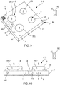
- the resistive cooktop 1.8 ( Figure 9 ) comprises a pot support structure forming the treating seat 5, as well as a resistive heating system 29 for heating pots or food in the treating position 6.
- the induction cooktop 1.9 ( Figure 9 ) comprises a pot support structure forming the treating seat 5, as well as a generator (e.g. an induction coil) 32 of a varying electromagnetic field in the treating position 6.
- a generator e.g. an induction coil
- the gas cooktop 1.7 ( Figure 10 ) comprises a pot support structure forming the treating seat 5, as well as a gas burner 33 adapted to heat pots or food in the treating position 6.
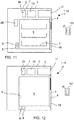
- the refrigerator 1.10 ( Figure 11 ) comprises a cooling cavity forming the treating seat 5 and which can be closed by a door 18, as well as a cooling and/or freezing system 34 adapted to cool and/or freeze the household products in the treating position 6 and optionally, a ventilation and/or air circulating system 28 for aerating the household products in the treating position 6.
- the freezer 1.11 ( Figure 12 ) comprises a freezing cavity forming the treating seat 5 and which can be closed by a door 18, as well as a freezing system 34 adapted to freeze the household products in the treating position 6.
- the vacuum cleaner 1.12 ( Figure 13 ) comprises a suction mouth for a furnishing surface forming the treating seat 5, as well as a ventilation system 28, in particular a suction system, of air from the furnishing surface in the treating position 6, and optionally, a mechanical moving 29a or agitation system for moving the treating seat 5.
- the ironing system 1.13 ( Figure 14 ) comprises a heatable plate forming the treating seat 5, as well as a heating system 29 for heating the heatable plate and a steam generator 31a for generating steam in the treating position 6.
- Each of the household appliances 1, 1.1 ... 1.13 described in greater detail may selectively comprise one or more of the treatment detectors 8 and selectively one or more of the anomaly detectors 9, in conjunction with the signal connections thereof with the electronic control system 10, described above and not repeated herein for brevity.
Landscapes
- Engineering & Computer Science (AREA)
- Computer Networks & Wireless Communication (AREA)
- Automation & Control Theory (AREA)
- Mechanical Engineering (AREA)
- Electromagnetism (AREA)
- Physics & Mathematics (AREA)
- Signal Processing (AREA)
- Human Computer Interaction (AREA)
- Textile Engineering (AREA)
- Chemical & Material Sciences (AREA)
- Combustion & Propulsion (AREA)
- General Engineering & Computer Science (AREA)
- Control Of Washing Machine And Dryer (AREA)
- Selective Calling Equipment (AREA)
Abstract
Description
- The present invention relates to a household appliance, in particular a washing machine, with a user interface for entering commands for controlling the operation of the household appliance.
- In generic terms, the household appliances referred to in the invention comprise:
- a housing which delimits a treating seat adapted to accommodate and/or support one or more household products (clothes, dishes, food products, furnishing surfaces, fabrics) in a treating position to subject them to a desired treatment,
- one or more treatment devices arranged inside the housing and operable to carry out one or more specific treatments at the treating position,
- one or more treatment detection devices arranged inside the housing and configured to detect one or more treatment parameter values of the treatment to which the household product is subjected in the treating position,
- optionally, one or more anomaly detectors arranged inside the housing and configured to detect one or more operating anomalies of the household appliance,
- an electronic control system arranged in the housing and in signal connection with the treatment device and with the treatment detector and, if provided, with the anomaly detector, and configured to control the operation of the treatment device depending on a treatment program and depending on the values detected by the treatment detector,
- a user interface in signal connection with the electronic control system to allow the user to select (parameters of) a treatment program of the household product and, optionally, to display parameters of the treatment program selected and/or being executed.
- In household appliances of the known art, the user interface is formed in one or more fixed areas of the housing or of the treating seat (refrigerator) and comprises a plurality of buttons or handles or capacitive touch sensors and, possibly, visual indicators, e.g. warning lights or a liquid crystal display (TFT) or OLED.
- The user interfaces of the household appliances of the known art were satisfactory at a time in which the development of treatment strategies and parameters of the household objects (e.g. clothes or dishes), of data communication and electronic control strategies and parameters were in pace with the development of the treatment equipment, with the evolution of the design of the household appliance housings and with the average duration of the household appliances.
- Currently, the treatment strategies of the household products, the electronic control and data communication technology, the amount of data and of treatment parameters available and potentially usable for controlling the household appliances and the aesthetical design of the household appliance housings are quickly evolving and frequently one is in conflict with the other or is "delayed" with respect to the other.
- A reason for dissatisfaction with the known household appliances is the impossibility of providing sufficiently large and extensive user interfaces for displaying the increased amount of treatment control information without spatially interfering with other components of the household appliance.
- A further reason for dissatisfaction with the known household appliances is the conflict between the need to have very large access openings or doors or hatches to facilitate the loading of the household products into the household appliance and the need to provide - often on the same front walls of the household appliance - free spaces for mounting the user interface, overall reduced outer sizes of the household appliances being equal.
- A further need not met to date is the one of providing a minimalist household appliance, from a functional, structural and comma design viewpoint, with just as minimalist a user interface in terms of the appearance and functionality thereof.
- A further need is to provide a household appliance that can be manufactured at very contained costs, is versatile in terms of the program selection and treatment parameters (e.g. of the clothes) and can be easily and quickly set and used for a treatment operation (e.g. clothes washing) conventionally used by the user.
- The aforesaid needs in particular refer to a household washing machine or washer-dryer for washing clothes. Subordinately, at least some of the aforesaid needs also refer to other types of household appliances.
- It is therefore the object of the present invention to provide a household appliance, in particular a washing machine or washer-dryer, having such a user interface as to obviate the drawbacks indicated with reference to the known art.
- These and other objects are achieved by a household appliance, in particular a washing machine or washer-dryer, with a user interface according to
claim 1. The dependent claims relate to advantageous and preferred embodiments. - According to an aspect of the invention, the user interface of the household appliance comprises an ON and OFF button, a first execution button of a preset fixed treatment program with preset and invariable treatment parameters, a second execution button of a versatile treatment program preset by the user with settable treatment parameters, a coupling (pairing) button, the activation of which carries out a wireless communication connection of the electronic control system with an electronic device that is external to the household appliance, for selecting and setting settable treatment parameters of the versatile treatment program by means of the external electronic device.
- Thereby, the total number of keys or buttons of the household appliance may be minimized, the space occupied by the user interface may be considerably reduced, the production costs of the household appliance may be reduced, in particular the costs for the pushbutton panel of the user interface, the quantity of mechanical and electronical components of the user interface potentially subject to wear or breakdown may be reduced, and therefore possible maintenance and repair operations may be minimized.
- In particular, the at least one preset fixed treatment program may be a treatment program prescribed by legislation or a treatment program used very frequently based on statistics on the use of the specific type of household appliance.
- Further advantageous aspects of the invention will become apparent from the following description of some embodiments thereof, given by way of non-limiting example, with reference to the accompanying Figures, in which:
-
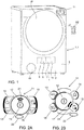
Figure 1 is a front view of a washing machine according to an embodiment of the invention, -
Figure 2A shows a user interface of a household appliance, in particular of the washing machine inFigure 1 , according to an embodiment, -
Figure 2B shows a user interface according to a further embodiment, -
Figure 2C is a front view of a detail of a washing machine according to a further embodiment, -
Figure 2D is a front view of a detail of a washing machine according to a further embodiment, -
Figure 3 is a diagrammatic view of a washing machine according to an embodiment, -
Figure 4 is a diagrammatic view of a dryer according to an embodiment, -
Figure 5 is a diagrammatic view of a washer-dryer according to an embodiment, -
Figure 6 is a diagrammatic view of a dishwasher according to an embodiment, -
Figure 7 is a diagrammatic view of a household oven according to an embodiment, -
Figure 8 is a diagrammatic view of the functional groups of a household microwave oven according to an embodiment, -
Figure 9 is a diagrammatic view of the functional groups of an electric or induction cooktop according to an embodiment, -
Figure 10 is a diagrammatic view of the functional groups of a gas cooktop according to an embodiment, -
Figure 11 is a diagrammatic view of the functional groups of a refrigerator according to an embodiment, -
Figure 12 is a diagrammatic view of the functional groups of a freezer according to an embodiment, -
Figure 13 is a diagrammatic view of the functional groups of a vacuum cleaner according to an embodiment, -
Figure 14 is a diagrammatic view of the functional groups of an ironing system according to an embodiment. - With reference to the drawings, a
household appliance 1 comprises: - a
housing 2 with anouter wall 3 forming anouter surface 4 of thehousehold appliance 1, - a treating
seat 5 adapted to accommodate and/or support household products in a treatingposition 6, - at least one
treatment device 7 arranged insidehousing 2 and operable to carry out a treatment at the treatingposition 6 and to subject the household product to said treatment, - at least one
treatment detector 8 at least partially arranged insidehousing 2 and configured to detect a value of a treatment parameter of the treatment carried out by thetreatment device 7, - optionally, at least one
anomaly detector 9 at least partially arranged insidehousing 2 and configured to detect a quantity indicating an operating anomaly of thehousehold appliance 1, - an
electronic control system 10 arranged inhousing 2 and in signal connection with thetreatment device 7 and with thetreatment detector 8 and configured to control thetreatment device 7 depending on a treatment program and depending on the value detected by thetreatment detector 8, - a
user interface 11 in signal connection with theelectronic control system 10. - According to an aspect of the invention, the
user interface 11 comprises: - an ON and
OFF button 12, the activation and deactivation of which turns thehousehold appliance 1 ON and OFF, respectively, - a
first execution button 13, the activation of which starts a fixed treatment program which is preset with preset and invariable treatment parameters, - a
second execution button 14, the activation of which starts a versatile treatment program which is preset with treatment parameters which can be set by the user, - a coupling (pairing)
button 15, the activation of which carries out a wireless communication connection of theelectronic control system 10 with an externalelectronic device 52, which is separate from thehousehold appliance 1, for example a smartphone or a tablet computer, for selecting and setting settable treatment parameters of the versatile treatment program by means of the externalelectronic device 52. - In this way, the total number of keys or buttons of the
household appliance 1 may be reduced, the space occupied by theuser interface 11 may be considerably reduced, the production costs of thehousehold appliance 1 may be reduced, in particular the costs for the pushbutton panel of theuser interface 11, the quantity of mechanical and electronical components of theuser interface 11 potentially subject to wear or breakdown may be reduced, and therefore possible maintenance and repair operations may be minimized. - In particular, the at least one preset fixed treatment program may be a treatment program prescribed by legislation or a treatment program used very frequently, based on statistics on the use of the specific type of
household appliance 1. - More than one preset fixed treatment program, for example two fixed programs prescribed by legislation on the subject of household appliances, may be provided for certain household appliances. Here, the
user interface 11 may comprise athird execution button 16 of a further fixed treatment program which is preset with preset and invariable treatment parameters. - According to an embodiment, the external
electronic device 52 comprises a computer program which is adapted to a remote control of thehousehold appliance 1 using the wireless communication connection between theelectronic control system 10 of thehousehold appliance 1 and the externalelectronic device 52, which is activated by operating thecoupling button 15. - By means of the computer program of the external
electronic device 52, the following is possible: - the settable treatment parameters of the versatile treatment program may be selected, in which the treatment program thus set becomes a default, or "preferred", treatment program which can be executed whenever the
second execution button 14 is operated, and/or - the parameters of a treatment program which can be executed by the
household appliance 1 and the start thereof may be selected and set directly by means of the externalelectronic device 52 without involving theexecution buttons user interface 11. - For this purpose, the
electronic control system 11 receives, from the externalelectronic device 52, a signal which encodes the treatment parameters selected by the user, stores the selected treatment parameters in an internal memory thereof and, in response to operating thesecond execution button 14, executes the versatile treatment program with the selected and stored treatment parameters. - In the absence of programming of the versatile treatment program by means of the external
electronic device 52, the versatile treatment program uses preset factory treatment parameters. - Even if the
electronic control system 10 does not find the selected treatment parameters stored in the internal memory thereof, instead of signaling an error, theelectronic control system 10 restores the preset factory treatment parameters for the versatile treatment program. - According to an embodiment, the
electronic control system 10 is configured to communicate to the externalelectronic device 52 the versatile treatment program with the treatment parameters currently stored in the internal memory thereof. - This allows the computer program of the external
electronic device 52 to display the treatment parameters currently set for the versatile treatment program so as to facilitate and speed up possible small modifications to the versatile treatment program. - According to the preferred embodiment, the
user interface 11 itself does not allow any selecting and setting of the settable treatment parameters of the versatile treatment program. - This allows a use of the
household appliance 1 in expert mode, by selecting, programming and setting treatment parameters by means of the externalelectronic device 52 as well as a highly simplified use of thehousehold appliance 1 by means of theexecution buttons electronic device 52 and dedicated computer program. - According to a further embodiment, in the absence of new programming by means of the external
electronic device 52, the versatile treatment program which can be activated by means of thesecond execution button 14 is automatically identical to the last treatment program executed by thehousehold appliance 1. - Thereby, an individual who is to repeatedly execute a same treatment program on an increased number of household objects, for example a same washing program on an increased quantity of clothes of the same type, may start the treatment program (e.g. washing) several times by operating the
second execution button 14 without any need to select or set individual treatment parameters (e.g. washing parameters). - According to a still further embodiment, in the absence of new programming by means of the external
electronic device 52, the versatile treatment program which can be activated by means of thesecond execution button 14 is automatically identical to the last treatment program executed by means of the operation of thesecond execution button 14. - This advantageously allows the fixed treatment program or the further fixed treatment program to be executed without influencing the settable treatment parameters of the versatile treatment program.
- Advantageously, the
user interface 11 comprises less than six buttons. Moreover, it is preferable for the user interface not to comprise any individual member for selecting a plurality of treatment programs or treatment parameters. This considerably simplifies the use of theuser interface 11, obviates the need to install multiple selection members, e.g. selection knobs, increases the life of theuser interface 11 and reduces the manufacturing costs and the need for maintenance. - According to embodiments, the ON and
OFF button 12 is a mechanical pressure button (pushbutton), for example a button which may take on a pressed position (in activated configuration), and a protruding position (in deactivated configuration), while the first 13, second 14, third 16 program execution buttons and thecoupling button 15 may be configured as touch keys, e.g. capacitive touch keys. This obviates the risk of turning thehousehold appliance 1 ON and OFF by only touching theON button 12, allows theprogram execution buttons coupling button 15 to be moved close to each other and to the mechanical ON andOFF button 12 in order to globally reduce the space occupied by theuser interface 11. - According to an advantageous embodiment, all the (five)
buttons user interface 11 are configured as touch buttons, e.g. as capacitive buttons, the outer surface of which (which is pressed by the user) may be pressed against the elastic resistance of an elastic element arranged at each of thebuttons - This reconciles the advantages of the touch technology with the need for the tactile perception of having triggered a treatment process.
- According to a preferred embodiment, the
user interface 11 has no alphanumeric display within the view of a rigorous simplification of the start process of the treatment program. - Advantageously, the
user interface 11 may comprise two warning lights (preferably LEDs) having different colors, for example afirst warning light 17 having a first color (e.g. green) and asecond warning light 21 having a second color (e.g. blue), which is different from the first color. Both warninglights household appliance 1 is OFF or in standby. The second warning light 21 (e.g. blue) is ON when thehousehold appliance 1 is ON and pending activation of one of the first 13, second 14, third 16 (when provided) execution buttons or thecoupling button 15. The first warning light 17 (e.g. green) is ON after the activation of one of the first 13, second 14, third 16 (when provided) execution buttons and during the execution of one of the respective fixed or versatile treatment programs. - According to a preferred embodiment, the
first warning light 17 and thesecond warning light 21 are obtained in a single optical warning area which lights up with the first color and with the second color, for example by means of a single multicolor LED. Theuser interface 11 may further comprise anaudible warning device 22 which emits an acoustic signal: - to confirm the operation of at least one of the execution buttons (13, 14, 16) or of the coupling button (15), and/or
- to confirm the completion of execution of the treatment program, and/or
- when one of the execution buttons (13, 14, 16) is pressed while an access door to the treating seat (5) is still open.
- According to embodiments:
- (condition 1) when the
household appliance 1 is OFF or in standby, i.e. when none of the buttons for theuser interface 11 is operated, the warning lights 17, 21 and theaudible warning device 22 are disabled. Here, anaccess door 18 to the treatingseat 5 is not locked and therefore may be opened. - (condition 2a) when the
ON button 12 is operated and the wireless connection is disconnected,- the
second warning light 21 is activated in a first warning light mode, e.g. constant light, - the
audible warning device 22 may emit an ON acoustic signal which signals the switch fromcondition 1 to condition 2a, - the
audible warning device 22 may emit a cycle end acoustic signal signaling the completion of a treatment program, - the
audible warning device 22 may emit a door open acoustic signal signaling anaccess door 18 to the treatingseat 5 is not closed, - the
audible warning device 22 may emit a remote controller disabled acoustic signal in response to a disconnection of the wireless connection by means of the operation of thecoupling button 15,
- the
- (condition 2b) when the
ON button 12 is operated and the wireless connection is connected by means of the operation of thecoupling button 15,- the
first warning light 17 is activated in a first warning light mode, e.g. constant light, - the
audible warning device 22 may emit a remote controller activated acoustic signal in response to the connection of the wireless connection by means of the operation of thecoupling button 15, - the
audible warning device 22 may emit a cycle end acoustic signal signaling the completion of a treatment program, - the
audible warning device 22 may emit a door open acoustic signal signaling anaccess door 18 to the treatingseat 5 is not closed,
- the
- (condition 3a) when the
ON button 12 is operated, wireless connection is disconnected and one of theexecution buttons - the
second warning light 21 is activated in a second warning light mode, e.g. pulsed light, - the
audible warning device 22 may emit a cycle start acoustic signal signaling the start of a treatment program, for example an execution triggered by the operation of one of theexecution buttons - the
audible warning device 22 may emit a remote controller disabled acoustic signal in response to a disconnection of the wireless connection by means of the operation of thecoupling button 15,
- the
- (condition 3b) when the
ON button 12 is operated, wireless connection is connected and one of theexecution buttons - the
first warning light 17 is activated in a second warning light mode, e.g. pulsed light, - the
audible warning device 22 may emit a cycle start acoustic signal signaling the start of a treatment program, for example an execution triggered by the operation of one of theexecution buttons - the
audible warning device 22 may emit a remote controller activation acoustic signal in response to a connection of the wireless connection by means of the operation of thecoupling button 15, starting, for example, fromcondition 3,
- the
- (condition 4) a Wi-Fi or Bluetooth enrolment process of the
electronic control system 10 of thehousehold appliance 1 in the control system carried out by means of the externalelectronic device 52 may be carried out by means of the combined operation of a plurality of thecoupling 15 andexecution second warning light 21 in blinking mode. - According to an embodiment, the settable program parameters of the versatile wash program may be selected and input only by means of the external
electronic device 52 and not also by means of theuser interface 11 of thehousehold appliance 1. This further contributes to a simplification and minimalist perception of the use of thehousehold appliance 1. - According to an embodiment, the
electronic control system 10 of thehousehold appliance 1 is connectable to the externalelectronic device 52 by means of a wireless communication connection or network, for example by means of Wi-Fi or Bluetooth. - According to an embodiment, the
user interface 11 is connected to a motherboard of theelectronic control system 10 by means of an I2C (I2C bus) communication protocol. Theelectronic control system 10 may comprise an integrated micro-controller (system on a chip) with integrated Wi-Fi and Bluetooth module for the wireless connection to the externalelectronic device 52. - According to embodiments, the
treatment devices 7 of thehousehold appliance 1 may comprise one or more of: - a
hydraulic system 27 for filling and emptying and/or circulating water to wet the household products in the treating position, - a ventilation and/or
air circulating system 28 for aerating the household products in the treating position, - a
heating system 29 for heating the household products and/or for heating the water of the hydraulic system and/or for heating the air of the ventilation system, - a
dehumidifying system 30 for drying the household products and/or for dehumidifying (for example through condensation) the air of theventilation system 28, - a
dispensing system 31 for dispensing one or more chemical treatment substances directly on the household product and/or in the water of thehydraulic system 27 and/or in the air of theventilation system 28, - a mechanical moving or
agitation system 29a for moving the household product and/or the treatingseat 5, for example for the purpose of rehydrating by means of centrifuge effect or of variation of exposure of the household product to thetreatment device 7 or of agitating and remixing the household product, - a
microwave generator 30a for generating microwaves in the treatingposition 6, - a
steam generator 31a for generating steam in the treatingposition 6, - a generator (e.g. an induction coil) 32 of a varying electromagnetic field adapted to generate an induced electromotive force (and therefore an induction heating) in electrically conductive pots in the treating
position 6, - a
gas burner 33 adapted to heat pots or food in the treatingposition 6, - a cooling and/or freezing
system 34 adapted to cool and/or freeze the household products in the treatingposition 6. - According to embodiments, the
treatment detectors 8 may comprise one or more of: - a water pressure sensor 35,
- a
water level sensor 36, - a
water temperature sensor 37, - an
air temperature sensor 38, - a treating
seat temperature sensor 39, - a
water torpidity sensor 40, - an
electrical quantity sensor 41 of an electric motor of the mechanical handling and/oragitation system 29, - a
presence sensor 42 of household products in the treatingposition 6, - a level or
presence sensor 43 of a chemical treatment substance in thedispensing system 31 of treatment substances, - a positioning sensor 44 of movable parts of the household appliance 1 (e.g.
door 18,auxiliary door 19,detergent drawer 45,filter 46,filter holder 47, dust bag 48), - a
flame presence sensor 49, - a camera 50 connected to or in
housing 2 and directed towards the treatingposition 6 to monitor the household product during the treatment. - According to embodiments, the
anomaly detectors 9 are also in signal connection with theelectronic control system 10 and may comprise one or more of a temperature sensor, a water presence sensor, a smoke presence sensor, a no water sensor, a position/presence sensor of movable or detachable parts of the household appliance (e.g.door 18,auxiliary door 19,detergent drawer 45,filter 46,filter holder 47, dust bag 48). - According to embodiments, the
electronic control system 10 controls the one ormore treatment devices 7 also depending on anomaly signals generated by theanomaly detectors 9. - The
household appliance 1 for example, is one of: - a washing machine 1.1 (
Figure 3 ), - a dryer 1.2 (
Figure 4 ), - a washer-dryer 1.3 (
Figure 5 ), - a dishwasher 1.4 (
Figure 6 ), - a household oven 1.5 (
Figure 7 ), - a microwave oven 1.6 (
Figure 8 ), - a gas cooktop 1.7 (
Figure 10 ) and/or resistive cooktop 1.8 (Figure 9 ) and/or induction cooktop 1.9 (Figure 9 ), - a refrigerator 1.10 (
Figure 11 ), - a freezer 1.10 (
Figure 12 ), - a vacuum cleaner 1.11 (
Figure 13 ), - an ironing apparatus 1.12 (
Figure 14 ). - According to embodiments, the household products which are treated by means of the
household appliance 1 may comprise one or more of: - clothes to be washed and/or dried and/or ironed,
- dishes to be washed,
- food products to be reheated and/or cooked and/or defrosted and/or frozen and/or cooled,
- furnishing surfaces to be dusted and/or cleaned,
- fabrics to be ironed or sewn.
- The washing machine 1.1 (
Figure 3 ) comprises a laundry drum 5' forming the treatingseat 5 and which can be closed by adoor 18, as well as ahydraulic system 27, awater heating system 29, a dispensingsystem 31, a movingsystem 29a. - The
user interface 11 of the washing machine 1.1 comprises: - the ON and
OFF button 12, the activation and deactivation of which turns the washing machine 1.1 ON and OFF, respectively, - the
first execution button 13, the activation of which starts a fixed wash program which is preset with preset and invariable washing parameters, - the
second execution button 14, the activation of which starts a versatile wash program which is preset with washing parameters which are settable by the user, - the coupling (pairing)
button 15, the activation of which carries out the aforesaid wireless communication connection of theelectronic control system 10 of the washing machine 1.1 with the externalelectronic device 52, for selecting and setting settable washing parameters of the versatile wash program by means of the externalelectronic device 52. - According to an embodiment, the washing machine 1.1 or washer-dryer comprises a support and
housing structure 2, inside which awashing tub 23 is housed, provided with a front opening which can be closed by means of aporthole door 18 hinged on the front ofhousing 2. A drum 5' (which forms the treating seat 5) is rotatably accommodated about a horizontal or inclined axis inside thewashing tub 23 to receive the clothes to be washed. Also the drum 5' delimits a front opening placed at the opening of thewashing tub 23 in order to load and unload the clothes. - The
washing tub 23 is adapted to contain the washing liquid during the clothes washing steps. - A
hydraulic system 27 connectable to the water supply network is provided to allow the loading oftub 23 with mains water. Thehydraulic system 27 may comprise a plurality of ducts extending, for example from one or more, e.g. two,supply solenoid valves 20, directly or through detergent compartments of a detergent tray 45 (optional), up to thewashing tub 3. - On the bottom of the
washing tub 23 is connected a drainage duct with associateddrain pump 24 which removes the washing liquid from thewashing tub 23 and which, together with thesupply solenoid valves 20, controls the level of liquid in thewashing tub 23. - A
heating system 29 may be provided to heat the washing liquid contained intub 3, for example an electrical resistance, arranged inside thewashing tub 23, in particular on the bottom of thewashing tub 23, in the gap between the wall of thewashing tub 23 and the laundry drum 5', - The laundry drum 5' may be activated in rotation by means of handling system 29 A, for example an electric motor and a drive, for example, to shake and mix the clothes with the washing liquid.
- The operation of the washing machine 1.1 is controlled by the
electronic control system 10 which is operatively connected to theuser interface 11. In response to the selections made by the user by means of theuser interface 11 and/or by means of the externalelectronic device 52, theelectronic control system 10 controls the various components of the washing machine 1.1 to automatically wash the clothes. - The washing machine 1.1 may further comprise a
dispensing system 31 of the "multiple dose" type for dispensing clothes treatment substances. - According to an embodiment, the washing machine 1.1 has no specific detergent container so that a detergent and/or other additives or treatment substances are to be placed by the user directly in the treating
seat 5, i.e. in the laundry drum 5', together with the clothes themselves. In this case, thehydraulic system 27 may comprise asingle solenoid valve 20 for the connection to the water supply network, as well as a duct extending from thesingle solenoid valve 20 directly into thewashing tub 23. - This allows obviating the installation of a second solenoid valve which directs a water flow into the detergent container.
- This configuration further simplifies the mechanical and hydraulic structure of the washing machine 1.1 and further reduces the manufacturing costs.
- The dryer 1.2 (
Figure 4 ) comprises a basket or laundry drum forming the treatingseat 5 and which can be closed by adoor 18, as well as aventilation system 28, anair heating system 29, adehumidifying system 30, a movingsystem 29a. - The washer-dryer 1.3 (
Figure 5 ) comprises a laundry drum forming the treatingseat 5 and which can be closed by adoor 18, as well as ahydraulic system 27, awater heating system 29, a dispensingsystem 31, a movingsystem 29a, aventilation system 28, anair heating system 29, adehumidifying system 30. - The dishwasher 1.4 (
Figure 6 ) comprises a receiving cavity forming the treatingseat 5 and which can be closed by adoor 18, as well as ahydraulic system 27, awater heating system 29, a dispensingsystem 31, and optionally, adehumidifying system 30. - The household oven 1.5 (
Figure 7 ) comprises a cooking cavity forming the treatingseat 5 and which can be closed by adoor 18, as well as aventilation system 28, aheating system 29 for heating the food products, optionally a moving system 29 A (e.g. for turning meat to be roasted), optionally asteam generator 31a for generating steam in the treatingposition 6, optionally agas burner 33 adapted to heat food in the treatingposition 6. - The microwave oven 1.6 (
Figure 8 ) comprises a cooking cavity forming the treatingseat 5 and which can be closed by adoor 18, as well as amicrowave generator 30a for generating microwaves in the treatingposition 6, a movingsystem 29a, optionally aventilation system 28. - The resistive cooktop 1.8 (
Figure 9 ) comprises a pot support structure forming the treatingseat 5, as well as aresistive heating system 29 for heating pots or food in the treatingposition 6. - The induction cooktop 1.9 (
Figure 9 ) comprises a pot support structure forming the treatingseat 5, as well as a generator (e.g. an induction coil) 32 of a varying electromagnetic field in the treatingposition 6. - The gas cooktop 1.7 (
Figure 10 ) comprises a pot support structure forming the treatingseat 5, as well as agas burner 33 adapted to heat pots or food in the treatingposition 6. - The refrigerator 1.10 (
Figure 11 ) comprises a cooling cavity forming the treatingseat 5 and which can be closed by adoor 18, as well as a cooling and/or freezingsystem 34 adapted to cool and/or freeze the household products in the treatingposition 6 and optionally, a ventilation and/orair circulating system 28 for aerating the household products in the treatingposition 6. - The freezer 1.11 (
Figure 12 ) comprises a freezing cavity forming the treatingseat 5 and which can be closed by adoor 18, as well as a freezingsystem 34 adapted to freeze the household products in the treatingposition 6. - The vacuum cleaner 1.12 (
Figure 13 ) comprises a suction mouth for a furnishing surface forming the treatingseat 5, as well as aventilation system 28, in particular a suction system, of air from the furnishing surface in the treatingposition 6, and optionally, a mechanical moving 29a or agitation system for moving the treatingseat 5. - The ironing system 1.13 (
Figure 14 ) comprises a heatable plate forming the treatingseat 5, as well as aheating system 29 for heating the heatable plate and asteam generator 31a for generating steam in the treatingposition 6. - Each of the
household appliances 1, 1.1 ... 1.13 described in greater detail may selectively comprise one or more of thetreatment detectors 8 and selectively one or more of theanomaly detectors 9, in conjunction with the signal connections thereof with theelectronic control system 10, described above and not repeated herein for brevity. - Obviously, a person skilled in the art, with the object of meeting contingent and specific needs, may make further changes and variations to the
household appliance 1 according to the present invention, all of which still falling within the scope of protection of the invention, which is defined by the following claims.
Claims (15)
- A household appliance (1) comprising:- a housing (2) with an outer wall (3) forming an outer surface (4) of the household appliance (1),- a treating seat (5) formed in or at the housing (2) and adapted to accommodate or support household products in a treating position (6),- at least one treatment device (7) arranged inside the housing (2) and operable for carrying out a treatment at the treating position (6) and subjecting the household product to said treatment,- at least one treatment detector (8) at least partially arranged inside the housing (2) and configured to detect a value of a treatment parameter of the treatment carried out by the treatment device (7),- optionally, at least one anomaly detector (9) at least partially arranged inside the housing (2) and configured to detect a quantity indicating an operating anomaly of the household appliance (1),- an electronic control system (10) arranged in the housing (2) and in signal connection with the treatment device (7) and with the treatment detector (8) and configured to control the treatment device (7) depending on a treatment program and depending on the value detected by the treatment detector (8),- a user interface (11) in signal connection with the electronic control system (10), said user interface (11) comprising:- a button (12) for turning ON and OFF the household appliance (1),- a first execution button (13), the activation of which starts a fixed treatment program which is preset with preset and invariable treatment parameters,- a second execution button (14), the activation of which starts a versatile treatment program which is preset with treatment parameters which can be set by the user,- a coupling button (15), the activation of which carries out a wireless communication connection of the electronic control system (10) with an external electronic device (52), which is separate from the household appliance (1), for example a smartphone or a tablet computer, for selecting and setting said settable treatment parameters of the versatile treatment program by means of the external electronic device (52).
- A household appliance (1) according to claim 1, wherein the user interface (11) comprises a third execution button (16), the activation of which starts a further fixed treatment program which is preset with preset and invariable treatment parameters.
- A household appliance (1) according to claim 1, wherein the at least one preset fixed treatment program is a treatment program prescribed by legislation.
- A household appliance (1) according to any one of the preceding claims combined with the external electronic device (52), wherein:- the external electronic device (52) comprises a computer program which is suitable for the remote control of the household appliance (1) using the wireless communication connection between the electronic control system (10) of the household appliance (1) and the external electronic device (52) which can be activated by operating the coupling button (15),- the settable treatment parameters of the versatile treatment program may be selected and set by means of the computer program for the external electronic device (52), wherein the treatment program thus set becomes a default treatment program which can be executed whenever the second execution button (14) is operated, wherein, optionally, by means of the computer program of the external electronic device (52), the parameters of a treatment program which can be executed by the household appliance (1) and the start thereof may be selected and set directly by means of the external electronic device (52) without involving the execution buttons (13, 14, 16) of the user interface (11),Wherein, optionally, the electronic control system (11):- receives, from the external electronic device (52), a signal which encodes the treatment parameters selected by the user,- stores the selected treatment parameters in an internal memory of the electronic control system (10),- in response to the operation of the second execution button (14), executes the versatile treatment program with the stored treatment parameters,and wherein:- in the absence of programming of the versatile treatment program by means of the external electronic device (52), the electronic control system (10) uses preset factory treatment parameters to execute the versatile treatment program,- if the electronic control system (10) does not find the settable treatment parameters stored in the internal memory thereof, the electronic control system (10) does not signal any error but restores the preset factory treatment parameters for the versatile treatment program.
- A household appliance (1) according to any one of the preceding claims, wherein the electronic control system (10) is configured to communicate to the external electronic device (52) the versatile treatment program with the treatment parameters currently stored in the internal memory of the electronic control system (10).
- A household appliance (1) according to any one of the preceding claims, wherein the user interface (11) itself does not allow any selecting and setting of the settable treatment parameters of the versatile treatment program.
- A household appliance (1) according to claim 1, wherein in the absence of new programming by means of the external electronic device (52), the versatile treatment program which can be activated by means of the second execution button (14) is automatically identical to the last treatment program executed by the household appliance (1).
- A household appliance (1) according to claim 1, wherein in the absence of new programing by means of the external electronic device (52), the versatile treatment program which can be activated by means of the second execution button (14) is automatically identical to the last treatment program executed by operating the second execution button (14),
and/or wherein the user interface (11) comprises less than six buttons and does not have any individual member for selecting a plurality of treatment programs or treatment parameters. - A household appliance (1) according to any one of the preceding claims, wherein the ON and OFF button (12) is a mechanical pressure button which may take a pressed position, in activated configuration, and a protruding position, in deactivated configuration, while the first (13), second (14), third (16) program execution buttons and the coupling button (15) are configured as touch keys.
- A household appliance (1) according to any one of claims 1 to 8, wherein all the buttons (12,13,14,15,16) of the user interface (11) are configured as touch buttons, the outer surface of which may be pressed against the elastic resistance of a spring positioned at each of the buttons (12,13,14,15,16).
- A household appliance (1) according to any one of the preceding claims, wherein the user interface (11) has no alphanumeric display but comprises a first warning light (17) having a first color and a second warning light (21) having a second color, different from the first color, wherein:- when the household appliance (1) is OFF or in standby, both the warning lights (17, 21) are disabled,- when the household appliance (1) is ON and awaiting activation of one of the execution buttons (13, 14, 16) or the coupling button (15), the second warning light (21) is ON,- after the activation of one of the execution buttons (13, 14, 16) and during the execution of one of the respective fixed or versatile treatment programs, the first warning light (17) is ON.
- A household appliance (1) according to claim 11, wherein the first warning light (17) and the second warning light (21) are obtained in a single optical warning area or by means of a single multicolor LED which lights up either with the first color or with the second color or remains OFF.
- A household appliance (1) according to any one of the preceding claims, wherein the user interface (11) further comprises an audible warning device (22) which emits an acoustic signal:- to confirm the operation of at least one of the execution buttons (13, 14, 16) or of the coupling button (15), and/or- to confirm the completion of execution of the treatment program, and/or- when one of the execution buttons (13, 14, 16) is pressed while an access door to the treating seat (5) is still open.
- A household appliance (1) according to any one of the preceding claims, wherein the household appliance (1) is a washing machine (1.1), comprising a laundry drum (5') which forms the treating seat (5) positioned inside a washing tub (23) and which can be closed by a door (18), and a hydraulic system (27), a water heating system (29), and handling system (29a), wherein:- an operation of the first execution button (13) starts a fixed wash program which is preset with preset and invariable washing parameters,- an operation of the second execution button (14) starts a versatile wash program which is preset with washing parameters which are settable by the user.
- A household appliance (1) according to claim 18, having no specific detergent container so that a detergent and other additives or treatment substances are to be placed by the user directly in the laundry drum (5') together with the clothes themselves,
wherein the hydraulic system (27) comprises only one single solenoid valve (20) for the connection to the water network, as well as a duct extending from the single solenoid valve (20) directly into the washing tub (23).
Applications Claiming Priority (1)
| Application Number | Priority Date | Filing Date | Title |
|---|---|---|---|
| IT102020000006397A IT202000006397A1 (en) | 2020-03-26 | 2020-03-26 | Washing machine with user interface |
Publications (2)
| Publication Number | Publication Date |
|---|---|
| EP3885483A1 true EP3885483A1 (en) | 2021-09-29 |
| EP3885483B1 EP3885483B1 (en) | 2025-06-25 |
Family
ID=70978388
Family Applications (1)
| Application Number | Title | Priority Date | Filing Date |
|---|---|---|---|
| EP21159211.8A Active EP3885483B1 (en) | 2020-03-26 | 2021-02-25 | Combination of a household appliance with user interface and an external electronic device |
Country Status (2)
| Country | Link |
|---|---|
| EP (1) | EP3885483B1 (en) |
| IT (1) | IT202000006397A1 (en) |
Cited By (1)
| Publication number | Priority date | Publication date | Assignee | Title |
|---|---|---|---|---|
| CN116643617A (en) * | 2023-06-01 | 2023-08-25 | 宁波方太厨具有限公司 | Knob, cooker and stove linkage system |
Citations (12)
| Publication number | Priority date | Publication date | Assignee | Title |
|---|---|---|---|---|
| KR20030054234A (en) * | 2001-12-24 | 2003-07-02 | 엘지전자 주식회사 | washing machine and operation method thereof |
| DE102006032087A1 (en) * | 2006-07-11 | 2008-01-24 | BSH Bosch und Siemens Hausgeräte GmbH | Programmatic home appliance with a simplified memory function and method for program input |
| DE102009047466A1 (en) * | 2009-12-03 | 2011-06-09 | BSH Bosch und Siemens Hausgeräte GmbH | Operating and display device for a control panel in a program-controlled household machine |
| WO2013021330A1 (en) * | 2011-08-05 | 2013-02-14 | Indesit Company S.P.A. | Household appliance and method for setting an operating program in such an appliance |
| EP2628841A1 (en) * | 2012-02-20 | 2013-08-21 | Indesit Company S.p.A. | Method and device for quickly turning on and activating a household appliance belonging to the white good category |
| DE102012101537A1 (en) * | 2012-02-27 | 2013-08-29 | Miele & Cie. Kg | Household appliance with a communication device |
| DE102014214836A1 (en) * | 2014-07-29 | 2016-02-04 | BSH Hausgeräte GmbH | Method for operating a household appliance |
| DE102016205703A1 (en) * | 2016-04-06 | 2017-10-12 | BSH Hausgeräte GmbH | Domestic appliance with a remote-controlled touch-sensitive display and control unit and method for its operation |
| US20170364048A1 (en) * | 2012-09-06 | 2017-12-21 | Lg Electronics Inc. | Home appliance and online system including the same |
| DE102017202334A1 (en) * | 2017-02-14 | 2018-08-16 | BSH Hausgeräte GmbH | Household appliance for the treatment of laundry items with improved operation, method for its operation and system comprising such a household appliance |
| US20190004690A1 (en) * | 2015-08-31 | 2019-01-03 | Bsh Hausgeraete Gmbh | Household Appliance Comprising An Operating Device Configured As An External Or Internal Touchscreen |
| DE102017218196A1 (en) * | 2017-10-12 | 2019-04-18 | BSH Hausgeräte GmbH | Laundry care device with a controller |
Family Cites Families (1)
| Publication number | Priority date | Publication date | Assignee | Title |
|---|---|---|---|---|
| KR20140032262A (en) * | 2012-09-06 | 2014-03-14 | 엘지전자 주식회사 | Home appliance and online system including the same |
-
2020
- 2020-03-26 IT IT102020000006397A patent/IT202000006397A1/en unknown
-
2021
- 2021-02-25 EP EP21159211.8A patent/EP3885483B1/en active Active
Patent Citations (12)
| Publication number | Priority date | Publication date | Assignee | Title |
|---|---|---|---|---|
| KR20030054234A (en) * | 2001-12-24 | 2003-07-02 | 엘지전자 주식회사 | washing machine and operation method thereof |
| DE102006032087A1 (en) * | 2006-07-11 | 2008-01-24 | BSH Bosch und Siemens Hausgeräte GmbH | Programmatic home appliance with a simplified memory function and method for program input |
| DE102009047466A1 (en) * | 2009-12-03 | 2011-06-09 | BSH Bosch und Siemens Hausgeräte GmbH | Operating and display device for a control panel in a program-controlled household machine |
| WO2013021330A1 (en) * | 2011-08-05 | 2013-02-14 | Indesit Company S.P.A. | Household appliance and method for setting an operating program in such an appliance |
| EP2628841A1 (en) * | 2012-02-20 | 2013-08-21 | Indesit Company S.p.A. | Method and device for quickly turning on and activating a household appliance belonging to the white good category |
| DE102012101537A1 (en) * | 2012-02-27 | 2013-08-29 | Miele & Cie. Kg | Household appliance with a communication device |
| US20170364048A1 (en) * | 2012-09-06 | 2017-12-21 | Lg Electronics Inc. | Home appliance and online system including the same |
| DE102014214836A1 (en) * | 2014-07-29 | 2016-02-04 | BSH Hausgeräte GmbH | Method for operating a household appliance |
| US20190004690A1 (en) * | 2015-08-31 | 2019-01-03 | Bsh Hausgeraete Gmbh | Household Appliance Comprising An Operating Device Configured As An External Or Internal Touchscreen |
| DE102016205703A1 (en) * | 2016-04-06 | 2017-10-12 | BSH Hausgeräte GmbH | Domestic appliance with a remote-controlled touch-sensitive display and control unit and method for its operation |
| DE102017202334A1 (en) * | 2017-02-14 | 2018-08-16 | BSH Hausgeräte GmbH | Household appliance for the treatment of laundry items with improved operation, method for its operation and system comprising such a household appliance |
| DE102017218196A1 (en) * | 2017-10-12 | 2019-04-18 | BSH Hausgeräte GmbH | Laundry care device with a controller |
Cited By (1)
| Publication number | Priority date | Publication date | Assignee | Title |
|---|---|---|---|---|
| CN116643617A (en) * | 2023-06-01 | 2023-08-25 | 宁波方太厨具有限公司 | Knob, cooker and stove linkage system |
Also Published As
| Publication number | Publication date |
|---|---|
| EP3885483B1 (en) | 2025-06-25 |
| IT202000006397A1 (en) | 2021-09-26 |
Similar Documents
| Publication | Publication Date | Title |
|---|---|---|
| US10745841B2 (en) | Systems and methods for controlling an appliance using another appliance communicatively coupled thereto | |
| US10612175B2 (en) | Automatic color composition detection for laundry washing machine | |
| CA1235467A (en) | Control system for a combined appliance | |
| US11898288B2 (en) | Household appliance with luminary communication interface | |
| CN105723156B (en) | household appliances | |
| CN110285641B (en) | Household appliance with user interface | |
| US20180160877A1 (en) | Methods of operating dishwasher with illuminable user interface | |
| US11066772B2 (en) | Laundry washing machine provided with a control panel | |
| EP3885483B1 (en) | Combination of a household appliance with user interface and an external electronic device | |
| KR100531333B1 (en) | Washing machine | |
| US10036115B2 (en) | Method of display for a laundry treating appliance | |
| US11293131B2 (en) | Appliance with hand held steam accessory | |
| EP4290989A1 (en) | Containment structure for a control unit of an appliance | |
| EP3038072A1 (en) | Electric product | |
| US10927487B2 (en) | Laundry washing machine provided with a control panel | |
| US10423869B1 (en) | Interchangeable tag communications systems for consumer appliances | |
| KR20180021433A (en) | Electronic Equipment and Control Method for the same | |
| US20250179711A1 (en) | System and method for remote monitoring and control of household appliances | |
| US20260064147A1 (en) | Household appliances with power supply adjustment | |
| US11773522B2 (en) | Household appliance guided provisioning | |
| US20260043184A1 (en) | Appliances contactless remote activation | |
| US20230263360A1 (en) | System and method for detecting unintentional button activation and implementing an automatic response | |
| RU2787682C2 (en) | Electrical household appliance with user interface | |
| US20230114475A1 (en) | Household appliance with personalized features | |
| RU2787761C2 (en) | Household electrical appliance with user interface |
Legal Events
| Date | Code | Title | Description |
|---|---|---|---|
| PUAI | Public reference made under article 153(3) epc to a published international application that has entered the european phase |
Free format text: ORIGINAL CODE: 0009012 |
|
| STAA | Information on the status of an ep patent application or granted ep patent |
Free format text: STATUS: THE APPLICATION HAS BEEN PUBLISHED |
|
| AK | Designated contracting states |
Kind code of ref document: A1 Designated state(s): AL AT BE BG CH CY CZ DE DK EE ES FI FR GB GR HR HU IE IS IT LI LT LU LV MC MK MT NL NO PL PT RO RS SE SI SK SM TR |
|
| STAA | Information on the status of an ep patent application or granted ep patent |
Free format text: STATUS: REQUEST FOR EXAMINATION WAS MADE |
|
| 17P | Request for examination filed |
Effective date: 20220208 |
|
| RBV | Designated contracting states (corrected) |
Designated state(s): AL AT BE BG CH CY CZ DE DK EE ES FI FR GB GR HR HU IE IS IT LI LT LU LV MC MK MT NL NO PL PT RO RS SE SI SK SM TR |
|
| STAA | Information on the status of an ep patent application or granted ep patent |
Free format text: STATUS: EXAMINATION IS IN PROGRESS |
|
| 17Q | First examination report despatched |
Effective date: 20231212 |
|
| RAP3 | Party data changed (applicant data changed or rights of an application transferred) |
Owner name: CANDY S.P.A. |
|
| RIN1 | Information on inventor provided before grant (corrected) |
Inventor name: LIGUORI, ANIELLO Inventor name: DE SILVA, DARIO Inventor name: SERGI, LEONARDO |
|
| GRAP | Despatch of communication of intention to grant a patent |
Free format text: ORIGINAL CODE: EPIDOSNIGR1 |
|
| STAA | Information on the status of an ep patent application or granted ep patent |
Free format text: STATUS: GRANT OF PATENT IS INTENDED |
|
| RIC1 | Information provided on ipc code assigned before grant |
Ipc: D06F 75/26 20060101ALN20250327BHEP Ipc: H05B 6/64 20060101ALI20250327BHEP Ipc: H05B 6/66 20060101ALI20250327BHEP Ipc: H05B 6/06 20060101ALI20250327BHEP Ipc: H04L 12/28 20060101ALI20250327BHEP Ipc: F24C 7/08 20060101ALI20250327BHEP Ipc: F24C 3/12 20060101ALI20250327BHEP Ipc: A47L 15/00 20060101ALI20250327BHEP Ipc: A47L 9/28 20060101ALI20250327BHEP Ipc: A47L 15/42 20060101ALI20250327BHEP Ipc: D06F 34/28 20200101ALI20250327BHEP Ipc: D06F 34/05 20200101AFI20250327BHEP |
|
| INTG | Intention to grant announced |
Effective date: 20250409 |
|
| RIN1 | Information on inventor provided before grant (corrected) |
Inventor name: LIGUORI, ANIELLO Inventor name: DE SILVA, DARIO Inventor name: SERGI, LEONARDO |
|
| GRAS | Grant fee paid |
Free format text: ORIGINAL CODE: EPIDOSNIGR3 |
|
| GRAA | (expected) grant |
Free format text: ORIGINAL CODE: 0009210 |
|
| STAA | Information on the status of an ep patent application or granted ep patent |
Free format text: STATUS: THE PATENT HAS BEEN GRANTED |
|
| AK | Designated contracting states |
Kind code of ref document: B1 Designated state(s): AL AT BE BG CH CY CZ DE DK EE ES FI FR GB GR HR HU IE IS IT LI LT LU LV MC MK MT NL NO PL PT RO RS SE SI SK SM TR |
|
| REG | Reference to a national code |
Ref country code: GB Ref legal event code: FG4D |
|
| REG | Reference to a national code |
Ref country code: CH Ref legal event code: EP |
|
| REG | Reference to a national code |
Ref country code: DE Ref legal event code: R096 Ref document number: 602021032669 Country of ref document: DE |
|
| REG | Reference to a national code |
Ref country code: CH Ref legal event code: EP |
|
| REG | Reference to a national code |
Ref country code: IE Ref legal event code: FG4D |
|
| PG25 | Lapsed in a contracting state [announced via postgrant information from national office to epo] |
Ref country code: FI Free format text: LAPSE BECAUSE OF FAILURE TO SUBMIT A TRANSLATION OF THE DESCRIPTION OR TO PAY THE FEE WITHIN THE PRESCRIBED TIME-LIMIT Effective date: 20250625 |
|
| REG | Reference to a national code |
Ref country code: LT Ref legal event code: MG9D |
|
| PG25 | Lapsed in a contracting state [announced via postgrant information from national office to epo] |
Ref country code: NO Free format text: LAPSE BECAUSE OF FAILURE TO SUBMIT A TRANSLATION OF THE DESCRIPTION OR TO PAY THE FEE WITHIN THE PRESCRIBED TIME-LIMIT Effective date: 20250925 Ref country code: GR Free format text: LAPSE BECAUSE OF FAILURE TO SUBMIT A TRANSLATION OF THE DESCRIPTION OR TO PAY THE FEE WITHIN THE PRESCRIBED TIME-LIMIT Effective date: 20250926 |
|
| PG25 | Lapsed in a contracting state [announced via postgrant information from national office to epo] |
Ref country code: BG Free format text: LAPSE BECAUSE OF FAILURE TO SUBMIT A TRANSLATION OF THE DESCRIPTION OR TO PAY THE FEE WITHIN THE PRESCRIBED TIME-LIMIT Effective date: 20250625 |
|
| PG25 | Lapsed in a contracting state [announced via postgrant information from national office to epo] |
Ref country code: HR Free format text: LAPSE BECAUSE OF FAILURE TO SUBMIT A TRANSLATION OF THE DESCRIPTION OR TO PAY THE FEE WITHIN THE PRESCRIBED TIME-LIMIT Effective date: 20250625 |
|
| PG25 | Lapsed in a contracting state [announced via postgrant information from national office to epo] |
Ref country code: RS Free format text: LAPSE BECAUSE OF FAILURE TO SUBMIT A TRANSLATION OF THE DESCRIPTION OR TO PAY THE FEE WITHIN THE PRESCRIBED TIME-LIMIT Effective date: 20250925 |
|
| PG25 | Lapsed in a contracting state [announced via postgrant information from national office to epo] |
Ref country code: LV Free format text: LAPSE BECAUSE OF FAILURE TO SUBMIT A TRANSLATION OF THE DESCRIPTION OR TO PAY THE FEE WITHIN THE PRESCRIBED TIME-LIMIT Effective date: 20250625 |
|
| REG | Reference to a national code |
Ref country code: NL Ref legal event code: MP Effective date: 20250625 |
|
| PG25 | Lapsed in a contracting state [announced via postgrant information from national office to epo] |
Ref country code: NL Free format text: LAPSE BECAUSE OF FAILURE TO SUBMIT A TRANSLATION OF THE DESCRIPTION OR TO PAY THE FEE WITHIN THE PRESCRIBED TIME-LIMIT Effective date: 20250625 |
|
| PG25 | Lapsed in a contracting state [announced via postgrant information from national office to epo] |
Ref country code: PT Free format text: LAPSE BECAUSE OF FAILURE TO SUBMIT A TRANSLATION OF THE DESCRIPTION OR TO PAY THE FEE WITHIN THE PRESCRIBED TIME-LIMIT Effective date: 20251027 |
|
| REG | Reference to a national code |
Ref country code: AT Ref legal event code: MK05 Ref document number: 1806531 Country of ref document: AT Kind code of ref document: T Effective date: 20250625 |
|
| PG25 | Lapsed in a contracting state [announced via postgrant information from national office to epo] |
Ref country code: IS Free format text: LAPSE BECAUSE OF FAILURE TO SUBMIT A TRANSLATION OF THE DESCRIPTION OR TO PAY THE FEE WITHIN THE PRESCRIBED TIME-LIMIT Effective date: 20251025 |
|
| PG25 | Lapsed in a contracting state [announced via postgrant information from national office to epo] |
Ref country code: SM Free format text: LAPSE BECAUSE OF FAILURE TO SUBMIT A TRANSLATION OF THE DESCRIPTION OR TO PAY THE FEE WITHIN THE PRESCRIBED TIME-LIMIT Effective date: 20250625 Ref country code: AT Free format text: LAPSE BECAUSE OF FAILURE TO SUBMIT A TRANSLATION OF THE DESCRIPTION OR TO PAY THE FEE WITHIN THE PRESCRIBED TIME-LIMIT Effective date: 20250625 |
|
| PG25 | Lapsed in a contracting state [announced via postgrant information from national office to epo] |
Ref country code: CZ Free format text: LAPSE BECAUSE OF FAILURE TO SUBMIT A TRANSLATION OF THE DESCRIPTION OR TO PAY THE FEE WITHIN THE PRESCRIBED TIME-LIMIT Effective date: 20250625 |
|
| PG25 | Lapsed in a contracting state [announced via postgrant information from national office to epo] |
Ref country code: PL Free format text: LAPSE BECAUSE OF FAILURE TO SUBMIT A TRANSLATION OF THE DESCRIPTION OR TO PAY THE FEE WITHIN THE PRESCRIBED TIME-LIMIT Effective date: 20250625 |
|
| PG25 | Lapsed in a contracting state [announced via postgrant information from national office to epo] |
Ref country code: EE Free format text: LAPSE BECAUSE OF FAILURE TO SUBMIT A TRANSLATION OF THE DESCRIPTION OR TO PAY THE FEE WITHIN THE PRESCRIBED TIME-LIMIT Effective date: 20250625 |
|
| PG25 | Lapsed in a contracting state [announced via postgrant information from national office to epo] |
Ref country code: SK Free format text: LAPSE BECAUSE OF FAILURE TO SUBMIT A TRANSLATION OF THE DESCRIPTION OR TO PAY THE FEE WITHIN THE PRESCRIBED TIME-LIMIT Effective date: 20250625 |
|
| PG25 | Lapsed in a contracting state [announced via postgrant information from national office to epo] |
Ref country code: ES Free format text: LAPSE BECAUSE OF FAILURE TO SUBMIT A TRANSLATION OF THE DESCRIPTION OR TO PAY THE FEE WITHIN THE PRESCRIBED TIME-LIMIT Effective date: 20250625 |
|
| PGFP | Annual fee paid to national office [announced via postgrant information from national office to epo] |
Ref country code: GB Payment date: 20260220 Year of fee payment: 6 |
|
| PG25 | Lapsed in a contracting state [announced via postgrant information from national office to epo] |
Ref country code: DK Free format text: LAPSE BECAUSE OF FAILURE TO SUBMIT A TRANSLATION OF THE DESCRIPTION OR TO PAY THE FEE WITHIN THE PRESCRIBED TIME-LIMIT Effective date: 20250625 |
|
| PGFP | Annual fee paid to national office [announced via postgrant information from national office to epo] |
Ref country code: DE Payment date: 20260223 Year of fee payment: 6 |
|
| PGFP | Annual fee paid to national office [announced via postgrant information from national office to epo] |
Ref country code: IT Payment date: 20251205 Year of fee payment: 6 |
|
| PGFP | Annual fee paid to national office [announced via postgrant information from national office to epo] |
Ref country code: FR Payment date: 20260130 Year of fee payment: 6 |
|
| PGFP | Annual fee paid to national office [announced via postgrant information from national office to epo] |
Ref country code: TR Payment date: 20260216 Year of fee payment: 6 |
|
| PLBE | No opposition filed within time limit |
Free format text: ORIGINAL CODE: 0009261 |
|
| STAA | Information on the status of an ep patent application or granted ep patent |
Free format text: STATUS: NO OPPOSITION FILED WITHIN TIME LIMIT |