EP3885270B1 - Feux de voie de circulation d'aérodrome - Google Patents
Feux de voie de circulation d'aérodrome Download PDFInfo
- Publication number
- EP3885270B1 EP3885270B1 EP21165072.6A EP21165072A EP3885270B1 EP 3885270 B1 EP3885270 B1 EP 3885270B1 EP 21165072 A EP21165072 A EP 21165072A EP 3885270 B1 EP3885270 B1 EP 3885270B1
- Authority
- EP
- European Patent Office
- Prior art keywords
- light
- taxiway
- prisms
- ldtf
- airfield
- Prior art date
- Legal status (The legal status is an assumption and is not a legal conclusion. Google has not performed a legal analysis and makes no representation as to the accuracy of the status listed.)
- Active
Links
- 230000003287 optical effect Effects 0.000 description 7
- RAQQRQCODVNJCK-JLHYYAGUSA-N N-[(4-amino-2-methylpyrimidin-5-yl)methyl]-N-[(E)-5-hydroxy-3-(2-hydroxyethyldisulfanyl)pent-2-en-2-yl]formamide Chemical compound C\C(N(Cc1cnc(C)nc1N)C=O)=C(\CCO)SSCCO RAQQRQCODVNJCK-JLHYYAGUSA-N 0.000 description 6
- 238000010586 diagram Methods 0.000 description 6
- 230000001105 regulatory effect Effects 0.000 description 3
- 238000004519 manufacturing process Methods 0.000 description 2
- 238000000034 method Methods 0.000 description 2
- 230000008520 organization Effects 0.000 description 2
- 238000007790 scraping Methods 0.000 description 2
- 230000003068 static effect Effects 0.000 description 2
- 230000000007 visual effect Effects 0.000 description 2
- 239000011521 glass Substances 0.000 description 1
- 238000012423 maintenance Methods 0.000 description 1
- 239000000463 material Substances 0.000 description 1
- 238000007789 sealing Methods 0.000 description 1
Images


Classifications
-
- B—PERFORMING OPERATIONS; TRANSPORTING
- B64—AIRCRAFT; AVIATION; COSMONAUTICS
- B64F—GROUND OR AIRCRAFT-CARRIER-DECK INSTALLATIONS SPECIALLY ADAPTED FOR USE IN CONNECTION WITH AIRCRAFT; DESIGNING, MANUFACTURING, ASSEMBLING, CLEANING, MAINTAINING OR REPAIRING AIRCRAFT, NOT OTHERWISE PROVIDED FOR; HANDLING, TRANSPORTING, TESTING OR INSPECTING AIRCRAFT COMPONENTS, NOT OTHERWISE PROVIDED FOR
- B64F1/00—Ground or aircraft-carrier-deck installations
- B64F1/18—Visual or acoustic landing aids
- B64F1/20—Arrangement of optical beacons
- B64F1/205—Arrangement of optical beacons arranged underground, e.g. underground runway lighting units
-
- B—PERFORMING OPERATIONS; TRANSPORTING
- B64—AIRCRAFT; AVIATION; COSMONAUTICS
- B64D—EQUIPMENT FOR FITTING IN OR TO AIRCRAFT; FLIGHT SUITS; PARACHUTES; ARRANGEMENT OR MOUNTING OF POWER PLANTS OR PROPULSION TRANSMISSIONS IN AIRCRAFT
- B64D47/00—Equipment not otherwise provided for
- B64D47/02—Arrangements or adaptations of signal or lighting devices
-
- B—PERFORMING OPERATIONS; TRANSPORTING
- B64—AIRCRAFT; AVIATION; COSMONAUTICS
- B64F—GROUND OR AIRCRAFT-CARRIER-DECK INSTALLATIONS SPECIALLY ADAPTED FOR USE IN CONNECTION WITH AIRCRAFT; DESIGNING, MANUFACTURING, ASSEMBLING, CLEANING, MAINTAINING OR REPAIRING AIRCRAFT, NOT OTHERWISE PROVIDED FOR; HANDLING, TRANSPORTING, TESTING OR INSPECTING AIRCRAFT COMPONENTS, NOT OTHERWISE PROVIDED FOR
- B64F1/00—Ground or aircraft-carrier-deck installations
- B64F1/002—Taxiing aids
-
- F—MECHANICAL ENGINEERING; LIGHTING; HEATING; WEAPONS; BLASTING
- F21—LIGHTING
- F21V—FUNCTIONAL FEATURES OR DETAILS OF LIGHTING DEVICES OR SYSTEMS THEREOF; STRUCTURAL COMBINATIONS OF LIGHTING DEVICES WITH OTHER ARTICLES, NOT OTHERWISE PROVIDED FOR
- F21V14/00—Controlling the distribution of the light emitted by adjustment of elements
- F21V14/06—Controlling the distribution of the light emitted by adjustment of elements by movement of refractors
-
- F—MECHANICAL ENGINEERING; LIGHTING; HEATING; WEAPONS; BLASTING
- F21—LIGHTING
- F21V—FUNCTIONAL FEATURES OR DETAILS OF LIGHTING DEVICES OR SYSTEMS THEREOF; STRUCTURAL COMBINATIONS OF LIGHTING DEVICES WITH OTHER ARTICLES, NOT OTHERWISE PROVIDED FOR
- F21V15/00—Protecting lighting devices from damage
- F21V15/01—Housings, e.g. material or assembling of housing parts
-
- F—MECHANICAL ENGINEERING; LIGHTING; HEATING; WEAPONS; BLASTING
- F21—LIGHTING
- F21V—FUNCTIONAL FEATURES OR DETAILS OF LIGHTING DEVICES OR SYSTEMS THEREOF; STRUCTURAL COMBINATIONS OF LIGHTING DEVICES WITH OTHER ARTICLES, NOT OTHERWISE PROVIDED FOR
- F21V29/00—Protecting lighting devices from thermal damage; Cooling or heating arrangements specially adapted for lighting devices or systems
- F21V29/50—Cooling arrangements
- F21V29/70—Cooling arrangements characterised by passive heat-dissipating elements, e.g. heat-sinks
-
- F—MECHANICAL ENGINEERING; LIGHTING; HEATING; WEAPONS; BLASTING
- F21—LIGHTING
- F21V—FUNCTIONAL FEATURES OR DETAILS OF LIGHTING DEVICES OR SYSTEMS THEREOF; STRUCTURAL COMBINATIONS OF LIGHTING DEVICES WITH OTHER ARTICLES, NOT OTHERWISE PROVIDED FOR
- F21V5/00—Refractors for light sources
- F21V5/007—Array of lenses or refractors for a cluster of light sources, e.g. for arrangement of multiple light sources in one plane
-
- F—MECHANICAL ENGINEERING; LIGHTING; HEATING; WEAPONS; BLASTING
- F21—LIGHTING
- F21V—FUNCTIONAL FEATURES OR DETAILS OF LIGHTING DEVICES OR SYSTEMS THEREOF; STRUCTURAL COMBINATIONS OF LIGHTING DEVICES WITH OTHER ARTICLES, NOT OTHERWISE PROVIDED FOR
- F21V5/00—Refractors for light sources
- F21V5/02—Refractors for light sources of prismatic shape
-
- B—PERFORMING OPERATIONS; TRANSPORTING
- B64—AIRCRAFT; AVIATION; COSMONAUTICS
- B64D—EQUIPMENT FOR FITTING IN OR TO AIRCRAFT; FLIGHT SUITS; PARACHUTES; ARRANGEMENT OR MOUNTING OF POWER PLANTS OR PROPULSION TRANSMISSIONS IN AIRCRAFT
- B64D2203/00—Aircraft or airfield lights using LEDs
-
- F—MECHANICAL ENGINEERING; LIGHTING; HEATING; WEAPONS; BLASTING
- F21—LIGHTING
- F21V—FUNCTIONAL FEATURES OR DETAILS OF LIGHTING DEVICES OR SYSTEMS THEREOF; STRUCTURAL COMBINATIONS OF LIGHTING DEVICES WITH OTHER ARTICLES, NOT OTHERWISE PROVIDED FOR
- F21V29/00—Protecting lighting devices from thermal damage; Cooling or heating arrangements specially adapted for lighting devices or systems
- F21V29/50—Cooling arrangements
- F21V29/70—Cooling arrangements characterised by passive heat-dissipating elements, e.g. heat-sinks
- F21V29/74—Cooling arrangements characterised by passive heat-dissipating elements, e.g. heat-sinks with fins or blades
- F21V29/76—Cooling arrangements characterised by passive heat-dissipating elements, e.g. heat-sinks with fins or blades with essentially identical parallel planar fins or blades, e.g. with comb-like cross-section
-
- F—MECHANICAL ENGINEERING; LIGHTING; HEATING; WEAPONS; BLASTING
- F21—LIGHTING
- F21W—INDEXING SCHEME ASSOCIATED WITH SUBCLASSES F21K, F21L, F21S and F21V, RELATING TO USES OR APPLICATIONS OF LIGHTING DEVICES OR SYSTEMS
- F21W2111/00—Use or application of lighting devices or systems for signalling, marking or indicating, not provided for in codes F21W2102/00 – F21W2107/00
- F21W2111/06—Use or application of lighting devices or systems for signalling, marking or indicating, not provided for in codes F21W2102/00 – F21W2107/00 for aircraft runways or the like
-
- F—MECHANICAL ENGINEERING; LIGHTING; HEATING; WEAPONS; BLASTING
- F21—LIGHTING
- F21Y—INDEXING SCHEME ASSOCIATED WITH SUBCLASSES F21K, F21L, F21S and F21V, RELATING TO THE FORM OR THE KIND OF THE LIGHT SOURCES OR OF THE COLOUR OF THE LIGHT EMITTED
- F21Y2115/00—Light-generating elements of semiconductor light sources
- F21Y2115/10—Light-emitting diodes [LED]
Definitions
- Airfield infrastructure can include terminals, hangars, maintenance facilities, etc. Airfields can further include runways, approach ways, taxiways, and/or intersections therebetween to direct aircraft traffic and/or other vehicles in and/or around the airfield.
- Airfields can include lighting systems to provide visual cues and/or signals for an airfield.
- airfield lighting systems can include airfield taxiway lights, such as taxiway centerline lights, to direct aircraft and/or other vehicles in and/or around the taxiways and/or intersections therebetween.
- the taxiway lights may, in some instances, have requirements mandated by regulatory bodies such as the International Civil Aviation Organization (ICAO) and/or Federal Aviation Administration (FAA), among others.
- IICAO International Civil Aviation Organization
- FAA Federal Aviation Administration
- Taxiway lights can provide a safe and efficient way to regulate airfield traffic.
- taxiway centerline lights may assist aircraft pilots in taxiing their aircraft between the runway and apron stands of the airfield.
- Taxiway centerline lights may be particularly useful at night, at a visual range of 350 meters or greater, and/or on complex taxiway intersections and exit taxiways.
- taxiway centerline toed (e.g., toe-in) lights and/or wide (e.g., ultra-wide) lights may be used on the centerline of curved portions of the taxiway along the designated taxiing paths of the taxiway.
- the beam nature of such lights allows the pilot to see the light from an offset angle, such as when maneuvering a curve of the taxiway.
- a wide light may be used in portions of the taxiway where the aircraft may be negotiating gradual curves, such as where the aircraft may take after a rapid exit from the runway.
- a toed light may be used.
- EP0898680B1 discloses a lighting device that includes a prism and a lamp that generates light rays.
- the lighting device also includes layers applied to the prism, such that the layers are between the lamp and the prism.
- JP5304904B2 discloses an indicator lamp that includes an LED light source, and light from the LED light source is emitted through a prism.
- JP2002008414A discloses an indicator lamp that uses a plurality of LEDs as a light source, and that the optical path of the light from the LEDs can be controlled using a prism lens
- US5669691A discloses a light fixture that includes a cover and an optical prism mounted in the cover, and that a sealing member can be fit over the prism.
- DE202009009583U1 discloses an underfloor light that includes LED light sources and prisms, and that the LED light sources emit light into the environment via the prisms.
- Airfield taxiway lights are described herein.
- an embodiment includes a plurality of light sources, a plurality of prisms through which light emitted by the plurality of light sources is configured to pass, wherein the light emitted by each respective light source passes through a different one of the plurality of prisms, and a cover having a plurality of openings through which the light that passes through the plurality of prisms is configured to exit the airfield taxiway light, wherein each respective opening is positioned over a different one of the plurality of prisms.
- Airfield taxiway lights e.g., taxiway centerline lights
- Airfield taxiway lights need to be able to withstand the weight loads of the aircraft using the taxiway.
- previous taxiway centerline lights e.g., conventional centerline toed and wide lights
- the cover e.g., top cover
- previous taxiway centerline lights may not be strong enough to withstand these increased weight loads.
- previous taxiway centerline lights may have bulky, expensive optics, which can increase the cost of the light (e.g., both the cost of the optical elements of the light and the cost of manufacturing the light), and increase the vulnerability of the light to various operating conditions of the taxiway.
- previous taxiway centerline lights may have a Fresnel lens made of glass (or equivalent material), which may require a large prism. This may cause the light to protrude more above ground level, which may cause the light to be more affected by the movement of the aircraft along the taxiway.
- previous taxiway centerline lights may have a long exit prism window, which can make the prism vulnerable to static loads and the scraping of snowplow blades on the taxiway.
- airfield taxiway lights e.g., taxiway centerline lights
- taxiway centerline lights in accordance with the present disclosure can withstand the increased weight loads of aircraft using the taxiway.
- taxiway centerline lights in accordance with the present disclosure may have a cover (e.g., a top cover) design that is capable of withstanding these increased weight loads.
- taxiway centerline lights in accordance with the present disclosure may have smaller (e.g., micro), cheaper optics than previous taxiway centerline lights, which can decrease the cost of the light (e.g., both the cost of the optical elements of the light and the cost of manufacturing the light), and decrease the vulnerability of the light to the operating conditions of the taxiway, as compared to previous taxiway centerline lights.
- taxiway centerline lights in accordance with the present disclosure may not use bulky, thick optical elements such as Fresnel lenses, which can reduce the cost of the light as compared with previous taxiway centerline lights, and reduce optical losses that may be caused by such optical elements.
- taxiway centerline lights in accordance with the present disclosure may use smaller prisms than previous taxiway centerline lights, which can increase the strength and longevity of the light. Further, taxiway centerline lights in accordance with the present disclosure may have a smaller exit prism window than previous taxiway centerline lights, which can make the prism of the light stronger and able to withstand static loads and the scraping of snowplow blades on the taxiway.
- taxiway centerline lights in accordance with the present disclosure can comply with requirements mandated by regulatory bodies such as the International Civil Aviation Organization (ICAO) and/or Federal Aviation Administration (FAA), among others.
- the light beams e.g., the properties of the light beams, such as the beam intensity, angle, full width at half maximum, and/or color
- the light beams can comply with the requirements mandated by such regulatory bodies.
- a can refer to one or more such things, while “a plurality of” something can refer to more than one such things.
- a number of prisms can refer to one or more prisms, while “a plurality of prisms” can refer to more than one prism.
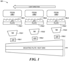
- Airfield taxiway light 101 can be, for instance, a taxiway centerline toed (e.g., toe left) light.
- airfield taxiway light 101 can include a mounting plate 111 that comprises a heat sink.
- Mounting plate 111 e.g., the heat sink
- the heat sink can be horizontally angled from left to right, as illustrated in Figure 1 .
- the heat sink can have an angle of 4 degrees relative to horizontal.
- airfield taxiway light 101 includes a plurality of light sources 110-1, 110-2, 110-3, which may be collectively referred to herein as light sources 110.
- light 101 includes three light sources 110.
- embodiments of the present are not so limited. For instance, some embodiments may include six light sources, as will be further described herein.
- light sources 110 can be arranged in a row.
- light sources 110-1 and 110-3 can be positioned at each side of the row, and light source 110-2 can be positioned between (e.g., in the middle of) light sources 110-1 and 110-3 in the row, as illustrated in Figure 1 .
- light sources 110 are light emitting diodes (LEDs).
- LEDs light emitting diodes
- light sources 110 can be arranged at the same angle as (e.g., horizontally angled with) mounting plate 111, as illustrated in Figure 1 .
- light sources 110 can be coupled to the heat sink of mounting plate 111.
- airfield taxiway light 101 can include a plurality of plates (e.g., prism support plates) 114-1, 114-2, 114-3, which may be collectively referred to herein as plates 114.
- the number of plates 114 (e.g., three) included in light 101 can be the same as the number of light sources 110 included in light 101 (e.g., three), as illustrated in Figure 1 .
- Plates 114 can be arranged in a row, as illustrated in Figure 1 .
- plates 114-1 and 114-3 can be positioned at each side of the row
- plate 114-2 can be positioned between (e.g., in the middle of) plates 114-1 and 114-3 in the row, as illustrated in Figure 1 .
- a light direction turning film (LDTF), collectively referred to herein as LDTF 116, can be coupled (e.g., attached) to plates 114 (e.g., to each respective plate 114-1, 114-2, 114-3).
- LDTF 116-1 can be coupled to plate 114-1
- LDTF 116-2 can be coupled to plate 114-2
- LDTF 116-3 can be coupled to plate 114-3, as illustrated in Figure 1
- LDTF 116 can be coupled to the sides of plates 114 that are opposite the sides of plates 114 that face light sources 110, as illustrated in Figure 1 .
- LDTF 116 can have a micro-prismatic structure, as illustrated in Figure 1 .
- the micro-prismatic structure of LDTF 116 can change the direction of light emitted by a light source (e.g., light sources 110), as will be further described herein.
- the direction in which the beam is turned depends on the orientation of the LDTF.
- the thickness of LDTF 116 can be, for instance, 0.254 mm (0.01 inch).
- airfield taxiway light 101 includes a plurality of prisms 118-1, 118-2, 118-3, which may be collectively referred to herein as prisms 118.
- the number of prisms 118 (e.g., three) included in light 101 can be the same as the number of light sources 110 included in light 101 (e.g., three), as illustrated in Figure 1 .
- Prisms 118 can be arranged in a row, as illustrated in Figure 1 .
- prisms 118-1 and 118-3 can be positioned at each side of the row, and prism 118-2 can be positioned between (e.g., in the middle of) light prisms 118-1 and 118-3 in the row, as illustrated in Figure 1 .
- each respective prism 118 can be supported by a different one of plates 114, such that LDTF 116 is located between each respective light source 110 and a different one of prisms 118.
- plate 114-1 can support prism 118-1 such that LDTF 116-1 is between light source 110-1 and prism 118-1
- plate 114-2 can support prism 118-2 such that LDTF 116-2 is between light source 110-2 and prism 118-2
- plate 114-3 can support prism 118-3 such that LDTF 116-3 is between light source 110-3 and prism 118-3, as illustrated in Figure 1 .
- embodiments are not limited to separate plates 114.
- prisms 118 can each be supported by a common plate.
- plates 114 can be coupled (e.g., linked) together.
- Light sources 110 can emit light.
- the light emitted by light sources 110 can undergo, and be controlled by, total internal reflection (TIR) within airfield taxiway light 101.
- TIR total internal reflection
- the light emitted by light source 110-1 can undergo narrow beam at TIR element 112-1
- the light emitted by light source 110-2 can undergo wide beam at TIR element 112-2
- the light emitted by light source 110-3 can undergo wide beam at TIR element 112-3, as illustrated in Figure 1 .
- the light emitted by light sources 110 passes through LDTF 116.
- the light emitted by each respective light source 110-1, 110-2, 110-3 passes through the LDTF 116-1, 116-2, 116-3 that is between that light source and the prism supported by the plate to which that LDTF is coupled.
- the light emitted by light source 110-1 passes through LDTF 116-1
- the light emitted by light source 110-2 passes through LDTF 116-2
- the light emitted by light source 110-3 passes through LDTF 116-3.
- LDTF 116 (e.g., the micro-prismatic structure of LDTF 116) can change the direction of (e.g., turn) the light.
- LDTF 116-1 can change the direction of the light emitted by light source 110-1
- LDTF 116-2 can change the direction of the light emitted by light source 110-2
- LDTF 116-3 can change the direction of the light emitted by light source 110-3.
- each respective LDTF 116 (e.g., each respective LDTF 116-1, 116-2, 116-3) can be oriented to change the direction of the light emitted by each respective light source 110-1, 110-2, 110-3 in the same direction (e.g., the orientation of each respective LDTF 116-1, 116-2, 116-3 can be the same, as illustrated in Figure 1 ).
- each respective LDTF 116-1, 116-2, 116-3 is oriented to turn (e.g., toe) the light emitted by each respective light source 110-1, 110-2, 110-3 to the left.
- the light passes through prisms 118.
- the light emitted by each respective light source 110-1, 110-2, 110-3 passes through a different one of prisms 118-1, 118-2, 118-3 (e.g., through the prism that is supported by the plate to which the LDTF through which that light passes is coupled).
- the light emitted by light source 110-1 passes through prism 118-1
- the light emitted by light source 110-2 passes through prism 118-2
- the light emitted by light source 110-3 passes through prism 118-3.
- the light can exit airfield taxiway light 101.
- the light can exit airfield taxiway light 101 through openings in the cover (e.g., top cover) of airfield taxiway light 101, as will be further described herein (e.g., in connection with Figures 4-6 ).
- Airfield taxiway light 202 can be, for instance, a taxiway centerline toed (e.g., toe right) light.
- airfield taxiway light 202 can include a mounting plate 221 that comprises a heat sink.
- Mounting plate 221 e.g., the heat sink
- the heat sink can be horizontally angled from right to left, as illustrated in Figure 2 .
- the heat sink can have an angle of 4 degrees relative to horizontal.
- airfield taxiway light 202 includes a plurality of light sources 220-1, 220-2, 220-3, which may be collectively referred to herein as light sources 220.
- light 202 includes three light sources 220.
- embodiments of the present are not so limited. For instance, some embodiments may include six light sources, as will be further described herein.
- light sources 220 can be arranged in a row.
- light sources 220-1 and 220-3 can be positioned at each side of the row, and light source 220-2 can be positioned between (e.g., in the middle of) light sources 220-1 and 220-3 in the row, as illustrated in Figure 2 .
- light sources 220 are LEDs.
- light sources 220 can be arranged at the same angle as (e.g., horizontally angled with) mounting plate 221, as illustrated in Figure 2 .
- light sources 220 can be coupled to the heat sink of mounting plate 221.
- airfield taxiway light 202 can include a plurality of plates (e.g., prism support plates) 224-1, 224-2, 224-3, which may be collectively referred to herein as plates 224.
- the number of plates 224 (e.g., three) included in light 202 can be the same as the number of light sources 220 included in light 202 (e.g., three), as illustrated in Figure 2 .
- Plates 224 can be arranged in a row, as illustrated in Figure 2 .
- plates 224-1 and 224-3 can be positioned at each side of the row
- plate 224-2 can be positioned between (e.g., in the middle of) plates 224-1 and 224-3 in the row, as illustrated in Figure 1 .
- a light direction turning film (LDTF), collectively referred to herein as LDTF 226, can be coupled (e.g., attached) to plates 224 (e.g., to each respective plate 224-1, 224-2, 224-3).
- LDTF 226-1 can be coupled to plate 224-1
- LDTF 226-2 can be coupled to plate 224-2
- LDTF 226-3 can be coupled to plate 224-3, as illustrated in Figure 2
- LDTF 226 can be coupled to the sides of plates 224 that are opposite the sides of plates 224 that face light sources 220, as illustrated in Figure 2 .
- LDTF 226 can have a micro-prismatic structure, as illustrated in Figure 2 .
- the micro-prismatic structure of LDTF 226 can change the direction of light emitted by a light source (e.g., light sources 220), as will be further described herein.
- the direction in which the beam is turned depends on the orientation of the LDTF.
- the thickness of LDTF 226 can be, for instance, 0.254 mm (0.01 inch).
- airfield taxiway light 202 includes a plurality of prisms 228-1, 228-2, 228-3, which may be collectively referred to herein as prisms 228.
- the number of prisms 228 (e.g., three) included in light 202 can be the same as the number of light sources 220 included in light 202 (e.g., three), as illustrated in Figure 2 .
- Prisms 228 can be arranged in a row, as illustrated in Figure 2 .
- prisms 228-1 and 228-3 can be positioned at each side of the row, and prism 228-2 can be positioned between (e.g., in the middle of) prisms 228-1 and 228-3 in the row, as illustrated in Figure 2 .
- each respective prism 228 can be supported by a different one of plates 224, such that LDTF 226 is located between each respective light source 220 and a different one of prisms 228.
- plate 224-1 can support prism 228-1 such that LDTF 226-1 is between light source 220-1 and prism 228-1
- plate 224-2 can support prism 228-2 such that LDTF 226-2 is between light source 220-2 and prism 228-2
- plate 224-3 can support prism 228-3 such that LDTF 226-3 is between light source 220-3 and prism 228-3, as illustrated in Figure 2 .
- Light sources 220 can emit light.
- the light emitted by light sources 220 can undergo, and be controlled by, total internal reflection (TIR) within airfield taxiway light 202.
- TIR total internal reflection
- the light emitted by light source 220-1 can undergo wide beam at TIR element 222-1
- the light emitted by light source 220-2 can undergo wide beam at TIR element 222-2
- the light emitted by light source 220-3 can undergo narrow beam at TIR element 222-3, as illustrated in Figure 2 .
- the light emitted by light sources 220 passes through LDTF 226.
- the light emitted by each respective light source 220-1, 220-2, 220-3 passes through the LDTF 226-1, 226-2, 226-3 that is between that light source and the prism supported by the plate to which that LDTF is coupled.
- the light emitted by light source 220-1 passes through LDTF 226-1
- the light emitted by light source 220-2 passes through LDTF 226-2
- the light emitted by light source 220-3 passes through LDTF 226-3.
- LDTF 226 (e.g., the micro-prismatic structure of LDTF 226) can change the direction of (e.g., turn) the light.
- LDTF 226-1 can change the direction of the light emitted by light source 220-1
- LDTF 226-2 can change the direction of the light emitted by light source 220-2
- LDTF 226-3 can change the direction of the light emitted by light source 220-3.
- LDTF 226 (e.g., each respective LDTF 226-1, 226-2, 226-3) can be oriented to change the direction of the light emitted by each respective light source 220-1, 220-2, 220-3 in the same direction (e.g., the orientation of each respective LDTF 226-1, 226-2, 226-3 can be the same, as illustrated in Figure 2 ).
- each respective LDTF 226-1, 226-2, 226-3 is oriented to turn (e.g., toe) the light emitted by each respective light source 220-1, 220-2, 220-3 to the right. That is, LDTF 226 can be orientated in the opposite direction from LDTF 116 described and illustrated in connection with Figure 1 .
- the light passes through prisms 228.
- the light emitted by each respective light source 220-1, 220-2, 220-3 passes through a different one of prisms 228-1, 228-2, 228-3 (e.g., through the prism that is supported by the plate to which the LDTF through which that light passes is coupled).
- the light emitted by light source 220-1 passes through prism 228-1
- the light emitted by light source 220-2 passes through prism 228-2
- the light emitted by light source 220-3 passes through prism 228-3.
- the light can exit airfield taxiway light 202.
- the light can exit airfield taxiway light 202 through openings in the cover (e.g., top cover) of airfield taxiway light 202, as will be further described herein (e.g., in connection with Figures 4-6 ).
- Airfield taxiway light 303 can be, for instance, a taxiway centerline wide (e.g., ultra-wide) light.
- airfield taxiway light 303 can include a mounting plate 364 that comprises a heat sink.
- Mounting plate 364 e.g., the heat sink
- airfield taxiway light 303 includes a plurality of light sources 330-1, 330-2, 330-3, which may be collectively referred to herein as light sources 330.
- light 303 includes three light sources 330.
- embodiments of the present are not so limited. For instance, some embodiments may include six light sources, as will be further described herein.
- light sources 330 can be arranged in a row.
- light sources 330-1 and 330-3 can be positioned at each side of the row, and light source 330-2 can be positioned between (e.g., in the middle of) light sources 330-1 and 330-3 in the row, as illustrated in Figure 1 .
- light sources 330 are LEDs.
- light sources 330 can be coupled to the heat sink of mounting plate 364.
- airfield taxiway light 303 can include a plurality of plates (e.g., prism support plates) 334-1, 334-2, 334-3, which may be collectively referred to herein as plates 334.
- the number of plates 334 (e.g., three) included in light 303 can be the same as the number of light sources 330 included in light 332 (e.g., three), as illustrated in Figure 3 .
- Plates 334 can be arranged in a row, as illustrated in Figure 3 .
- plates 334-1 and 334-3 can be positioned at each side of the row
- plate 334-2 can be positioned between (e.g., in the middle of) plates 334-1 and 334-3 in the row, as illustrated in Figure 3 .
- a light direction turning film (LDTF), collectively referred to herein as LDTF 336, can be coupled (e.g., attached) to two of the plates 324.
- LDTF 336 can be coupled to the plates positioned at each side (e.g., the outer plates) of the row.
- LDTF 336-1 can be coupled to plate 334-1
- LDTF 336-2 can be coupled to plate 334-3, as illustrated in Figure 3 .
- LDTF 336-1 and 336-2 can be coupled to the sides of plates 334-1 and 334-3, respectively, that are opposite the sides of plates 334-1 and 334-3 that face light sources 330-1 and 330-3, respectively, as illustrated in Figure 3 .
- no LDTF is coupled to the third of the plates 324.
- no LDTF is coupled to the plate positioned in the middle (e.g., the middle plate) of the row.
- no LDTF is coupled to plate 334-2, as illustrated in Figure 3 .
- LDTF 336 can have a micro-prismatic structure, as illustrated in Figure 3 .
- the micro-prismatic structure of LDTF 336 can change the direction of light emitted by a light source (e.g., light sources 330-1 and 330-3), as will be further described herein.
- the direction in which the beam is turned depends on the orientation of the LDTF.
- the thickness of LDTF 336 can be, for instance, 0.254 mm (0.01 inch).
- airfield taxiway light 303 includes a plurality of prisms 338-1, 338-2, 338-3, which may be collectively referred to herein as prisms 338.
- the number of prisms 338 (e.g., three) included in light 303 can be the same as the number of light sources 330 included in light 303 (e.g., three), as illustrated in Figure 3 .
- Prisms 338 can be arranged in a row, as illustrated in Figure 3 .
- prisms 338-1 and 338-3 can be positioned at each side of the row, and prism 338-2 can be positioned between (e.g., in the middle of) prisms 338-1 and 338-3 in the row, as illustrated in Figure 2 .
- each respective prism 338 can be supported by a different one of plates 334.
- plate 334-1 can support prism 338-1 such that LDTF 336-1 is between light source 330-1 and prism 338-1
- plate 334-2 can support prism 338-2 such that no LDTF is between light source 330-2 and prism 338-2
- plate 334-3 can support prism 338-3 such that LDTF 336-2 is between light source 330-3 and prism 338-3, as illustrated in Figure 3 .
- Light sources 330 can emit light.
- the light emitted by light sources 330 can undergo, and be controlled by, total internal reflection (TIR) within airfield taxiway light 303.
- TIR total internal reflection
- the light emitted by light source 330-1 can undergo narrow beam at TIR element 332-1
- the light emitted by light source 330-2 can undergo wide beam at TIR element 332-2
- the light emitted by light source 330-3 can undergo narrow beam at TIR element 332-3, as illustrated in Figure 3 .
- the light emitted by light sources 330-1 and 330-3 passes through the LDTF 336 that is between that light source and the prism supported by the plate to which that LDTF is coupled.
- the light emitted by light source 330-1 passes through LDTF 336-1
- the light emitted by light source 330-3 passes through LDTF 336-2.
- the light emitted by light source 330-2 may not pass through a LDTF.
- the LDTFs can change the direction of (e.g., turn) the light.
- LDTF 336-1 can change the direction of the light emitted by light source 330-1
- LDTF 336-3 can change the direction of the light emitted by light source 330-3.
- the light emitted by light source 330-2 does not pass through a LDTF, its direction does not change (e.g., its direction is not turned).
- LDTF 326-1 can be oriented to change the direction of the light emitted by light source 320-1 in a first direction
- LDTF 326-2 can be oriented to change the direction of the light emitted by light source 320-3 in a second direction that is opposite the first direction (e.g., the orientation of LDTF 326-1 can be opposite the orientation of LDTF 326-2, as illustrated in Figure 3 ).
- LDTF 336-1 is oriented to turn the light emitted by light source 320-1 to the left
- LDTF 336-2 is oriented to turn the light emitted by light source 320-3 to the right.
- the light emitted by light sources 330-1 and 330-3 passes through (e.g., is turned by) LDTFs 336-1 and 336-2, respectively, the light passes through prisms 338-1 and 338-3, respectively. Further, the light emitted by light source 330-2 can pass through prism 338-2 without first passing through a LDTF. As such, in the example illustrated in Figure 3 , the light emitted by light source 330-1 passes through prism 338-1 after being turned to the left, the light emitted by light source 330-2 can pass through prism 338-2 without being turned, and the light emitted by light source 330-3 passes through prism 338-3 after being turned to the right.
- the light can exit airfield taxiway light 303.
- the light can exit airfield taxiway light 303 through openings in the cover (e.g., top cover) of airfield taxiway light 303, as will be further described herein (e.g., in connection with Figures 4-6 ).
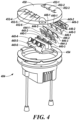
- Airfield taxiway light 404 can be, for instance, a taxiway centerline toed (e.g., toe right or toe left) light.
- airfield taxiway light 404 can be airfield taxiway light 101 previously described in connection with Figure 1 or airfield taxiway light 202 previously described in connection with Figure 2 .
- airfield taxiway light 404 can include a mounting plate 454 that comprises a heat sink. Further, airfield light 404 includes a plurality of light sources 440-1, 440-2, 440-3, 440-4, 440-5, 440-6, which may be collectively referred to herein as light sources 440. Light sources 440 can be coupled to mounting plate 454 (e.g., to the heat sink), as illustrated in Figure 4 .
- airfield taxiway light 404 includes six light sources 440, which can be arranged in two different rows.
- light sources 440-1, 440-2, and 440-3 can be a first row of light sources that face a first direction and are analogous to light sources 110-1, 110-2, 110-3 previously described in connection with Figure 1 or light sources 220-1, 220-2, 220-3 previously described in connection with Figure 2
- light sources 440-4, 440-5, and 440-6 can be a second row of light sources that face a second direction and are also analogous to light sources 110-1, 110-2, 110-3 or light sources 220-1, 220-2, 220-3.
- light sources 440 can emit light in a manner analogous to light sources 110 or 220.
- airfield taxiway light 404 can include plates (e.g., prism support plates) 444-1, 444-2, 444-3, which may be collectively referred to herein as plates 444.
- Plates 444-1, 444-2, and 444-3 can be a first row of plates that are analogous to plates 114-1, 114-2, 114-3 previously described in connection with Figure 1 or plates 224-1, 224-2, 224-3 previously described in connection with Figure 2 .
- airfield taxiway light 404 can also include a second row of three plates that are also analogous to plates 114-1, 114-2, 114-3 or plates 224-1, 224-2, 224-3.
- airfield taxiway light 404 includes LDTFs 446-1, 446-2, 446-3, which may be collectively referred to as LDTF 446.
- LDTF 446 can be analogous to LDTF 116 previously described in connection with Figure 1 or LDTF 226 previously described in connection with Figure 2 .
- LDTFs 446-1, 446-2, and 446-3 can be coupled to plates 444-1, 444-2, and 444-3, respectively, in a manner analogous to that previously described in connection with Figure 1 or Figure 2 .
- airfield taxiway light 404 can also include an analogous LDTF that can be coupled to the three plates of the second row of plates in an analogous manner.
- the light emitted by light sources 440 passes through LDTF 446 and the LDTF coupled to the three plates of the second row of plates in a manner analogous to that previously described in connection with Figure 1 or Figure 2 .
- the LDTFs e.g., the micro-prismatic structure of the LDTFs
- the direction of (e.g., turn) the light in a manner analogous to that previously described in connection with Figure 1 or Figure 2 .
- the light emitted by light sources 440 may be turned to the left, and if the LDTFs are analogous to LDTF 226 previously described in connection with Figure 2 , the light emitted by light sources 440 may be turned to the right.
- airfield taxiway light 404 includes prisms 448-1, 448-2, 448-3, which may be collectively referred to herein as prisms 448.
- Prisms 448-1, 448-2, and 448-3 can be a first row of prisms that are analogous to prisms 118-1, 118-2, 118-3 previously described in connection with Figure 1 or prisms 228-1, 228-2, 228-3 previously described in connection with Figure 2 .
- prisms 448-1, 448-2, 448-3 can be supported by plates 444-1, 444-2, 444-3, respectively, such that LDTF 446 is between each respective light source 440 and prisms 444, in a manner analogous to that previously described in connection with Figure 1 or Figure 2 .
- LDTF 446 is between each respective light source 440 and prisms 444, in a manner analogous to that previously described in connection with Figure 1 or Figure 2 .
- the light passes through prisms 448, in a manner analogous to that previously described in connection with Figure 1 or Figure 2 .
- airfield taxiway light 404 can also include a second row of three prisms that are also analogous to prisms 118-1, 118-2, 118-3 or prisms 228-1, 228-2, 228-3.
- airfield taxiway light 404 can include prism covers 449-1, 449-2, 449-3, which may be collectively referred to as prism covers 449.
- Each respective prism 448 can be covered by a different one of prism covers 449 to provide protection for prisms 448.
- prism 448-1 can be covered (e.g., protected) by cover 449-1
- prism 448-2 can be covered by cover 449-2
- prism 448-3 can be covered by cover 449-3, as illustrated in Figure 4 .
- airfield taxiway light 404 can also include three additional prism covers analogous to prism covers 449 to cover the three respective prisms of second row of prisms.
- airfield taxiway light 404 includes a cover (e.g., top cover) 450.
- Cover 450 includes a plurality of openings (e.g., windows) 452-1, 452-2, 452-3, 452-4, 452-5, 452-6, which may be collectively referred to herein as openings 452, as illustrated in Figure 4 .
- the number of openings 452 (e.g., six) included in cover 450 can be the same as the number of light sources 440 included in airfield taxiway light 404 (e.g., six).
- Openings 452 can be arranged in two different rows, as illustrated in Figure 4 , such that each respective opening 452 is positioned over a different one of the prisms of airfield taxiway light 404.
- openings 452-1, 452-2, and 452-3 can be arranged in a first row of openings in cover 450, with opening 452-1 positioned over prism 448-1, opening 452-2 positioned over prism 448-2, and opening 452-3 positioned over prism 448-3.
- openings 452-4, 452-5, 452-6 can be arranged in a second row of openings in cover 450, with opening 452-4 positioned over a first prism of the second row of three prisms, opening 452-5 positioned over a second (e.g., the middle) prism of the second row of three prisms, and opening 452-6 positioned over a third prism of the second row of the three prisms.
- the light can exit airfield taxiway light 404 through openings 452.
- the light that passes through each respective prism can exit airfield taxiway light 404 through a different opening 452 (e.g., through the opening that is positioned over that respective prism).
- the light that passes through prism 448-1 can exit light 404 through opening 452-1
- the light that passes through prism 448-2 can exit light 404 through pending 452-2
- the light that passes through prism 448-3 can exit light 404 through opening 452-3
- the light that passes through the first prism of the second row of three prisms can pass through opening 452-4
- the light that passes through the second prism of the second row of three prisms can pass through opening 452-5
- the light that passes through the third prism of the second row of three prisms can pass through opening 452-6.
- the light can exit airfield taxiway light 404 through openings 452 such that the light is visible (e.g., to a pilot of an aircraft travelling on the taxiway) from a vertical angle of 1 degree relative to cover 450 to a vertical angle of 10 degrees relative to cover 450.
- the light can exit light 404 through openings 452 such that the light is visible from a horizontal angle of 3.5 degrees relative to cover 450 to a horizontal angle of -35 degrees relative to cover 450.
- the light can exit light 404 through openings 452 such that the light is visible from a horizontal angle of -3.5 degrees relative to cover 450 to a horizontal angle of 35 degrees relative to cover 450.
- Airfield taxiway light 503 can be, for instance, a taxiway centerline wide (e.g., ultra-wide) light.
- Airfield taxiway light 503 can be airfield taxiway light 303 previously described in connection with Figure 3 .
- airfield taxiway light 503 can include a mounting plate 564 that comprises a heat sink. Further, airfield light 503 includes a plurality of light sources 530-1, 530-2, 530-3, 530-4, 530-5, 530-6, which may be collectively referred to herein as light sources 530. Light sources 530 can be coupled to mounting plate 564 (e.g., to the heat sink), as illustrated in Figure 5 .
- airfield taxiway light 503 includes six light sources 530, which can be arranged in two different rows.
- light sources 530-1, 530-2, and 530-3 can be a first row of light sources that face a first direction and are analogous to light sources 330-1, 330-2, 330-3 previously described in connection with Figure 3
- light sources 330-4, 330-5, and 330-6 can be a second row of light sources that face a second direction and are also analogous to light sources 330-1, 330-2, 330-3.
- light sources 530 can emit light in a manner analogous to light sources 330.
- airfield taxiway light 503 can include plates (e.g., prism support plates) 534-1, 534-2, 534-3, which may be collectively referred to herein as plates 534.
- Plates 534-1, 534-2, and 534-3 can be a first row of plates that are analogous to plates 334-1, 334-2, 334-3 previously described in connection with Figure 3 .
- airfield taxiway light 503 can also include a second row of three plates that are also analogous to plates 334-1, 334-2, 334-3.
- airfield taxiway light 503 includes LDTFs 536-1, 536-2, which may be collectively referred to as LDTF 536.
- LDTF 536 can be analogous to LDTF 336 previously described in connection with Figure 3 .
- LDTFs 536-1 and 536-2 can be coupled to plates 534-1 and 534-3, respectively, in a manner analogous to that previously described in connection with Figure 3 .
- airfield taxiway light 503 can also include an analogous LDTF that can be coupled to the two outer plates of the second row of plates in an analogous manner.
- the light emitted by light sources 530-1 and 530-3 passes through LDTF 536-1 and 536-2, respectively, and the light emitted by light sources 530-4 and 530-6 passes through the LDTF coupled to the outer two plates of the second row of plates, in a manner analogous to that previously described in connection with Figure 3 .
- the light emitted by light sources 530-2 and 530-5 may not pass through a LDTF.
- the LDTFs can change the direction of (e.g., turn) the light, in a manner analogous to that previously described in connection with Figure 3 .
- the light emitted by light sources 530-1 and 530-4 may turn in a first direction (e.g., to the left), and the light emitted by light sources 530-3 and 530-6 may turn in a second direction (e.g., to the right), in a manner analogous to that previously described in connection with Figure 3 .
- the light emitted by light sources 530-2 and 530-5 may not turn.
- airfield taxiway light 503 includes prisms 538-1, 538-2, 538-3, which may be collectively referred to herein as prisms 538.
- Prisms 538-1, 538-2, and 538-3 can be a first row of prisms that are analogous to prisms 338-1, 338-2, 338-3 previously described in connection with Figure 3 .
- prisms 538-1, 538-2, 538-3 can be supported by plates 534-1, 534-2, 534-3, respectively, such that LDTF 536-1 is between light source 530-1 and prism 538-1 and LDTF 536-3 is between light source 530-3 and prism 538-3, in a manner analogous to that previously described in connection with Figure 3 .
- LDTF 536-1 is between light source 530-1 and prism 538-1
- LDTF 536-3 is between light source 530-3 and prism 538-3, in a manner analogous to that previously described in connection with Figure 3 .
- airfield taxiway light 503 can also include a second row of three prisms that are also analogous to prisms 538-1, 538-2, 538-3.
- airfield taxiway light 404 can include prism covers 559-1, 559-2, 559-3, which may be collectively referred to as prism covers 559.
- Each respective prism 538 can be covered by a different one of prism covers 559 to provide protection for prisms 538.
- prism 538-1 can be covered (e.g., protected) by cover 559-1
- prism 538-2 can be covered by cover 559-2
- prism 538-3 can be covered by cover 559-3, as illustrated in Figure 5 .
- airfield taxiway light 503 can also include three additional prism covers analogous to prism covers 559 to cover the three respective prisms of second row of prisms.
- airfield taxiway light 503 includes a cover (e.g., top cover) 560.
- Cover 560 includes a plurality of openings (e.g., windows) 562-1, 562-2, 562-3, 562-4, 562-5, 562-6, which may be collectively referred to herein as openings 562, as illustrated in Figure 5 .
- the number of openings 562 (e.g., six) included in cover 560 can be the same as the number of light sources 530 included in airfield taxiway light 503 (e.g., six).
- Openings 562 can be arranged in two different rows, as illustrated in Figure 5 , such that each respective opening 562 is positioned over a different one of the prisms of airfield taxiway light 503.
- openings 562-1, 562-2, and 562-3 can be arranged in a first row of openings in cover 560, with opening 562-1 positioned over prism 538-1, opening 562-2 positioned over prism 538-2, and opening 562-3 positioned over prism 538-3.
- openings 562-4, 562-5, 562-6 can be arranged in a second row of openings in cover 560, with opening 562-4 positioned over a first prism of the second row of three prisms, opening 562-5 positioned over a second (e.g., the middle) prism of the second row of three prisms, and opening 562-6 positioned over a third prism of the second row of the three prisms.
- the light can exit airfield taxiway light 503 through openings 562.
- the light that passes through each respective prism can exit airfield taxiway light 503 through a different opening 562 (e.g., through the opening that is positioned over that respective prism).
- the light that passes through prism 538-1 can exit light 503 through opening 562-1
- the light that passes through prism 538-2 can exit light 503 through pending 562-2
- the light that passes through prism 538-3 can exit light 503 through opening 562-3
- the light that passes through the first prism of the second row of three prisms can pass through opening 562-4
- the light that passes through the second prism of the second row of three prisms can pass through opening 562-5
- the light that passes through the third prism of the second row of three prisms can pass through opening 562-6.
- the light can exit airfield taxiway light 503 through openings 562 such that the light is visible (e.g., to a pilot of an aircraft travelling on the taxiway) from a vertical angle of 1 degree relative to cover 450 to a vertical angle of 10 degrees relative to cover 450. Further, the light can exit airfield taxiway light 503 through openings 562 such that the light is visible from an azimuth angle of -30 degrees relative to cover 560 to an azimuth angle of 30 degrees relative to cover 560.
- Figure 6 illustrates an overhead view of an example cover (e.g., top cover) 670 of an airfield taxiway light in accordance with an embodiment of the present disclosure.
- Cover 670 can be, for example, cover 450 previously described in connection with Figure 4 or cover 560 previously described in connection with Figure 5 .
- cover 670 includes a plurality of openings (e.g., windows) 672-1, 672-2, 672-3, 672-4, 672-5, 672-6, which may be collectively referred to herein as openings 672.
- Openings 672 can be analogous to openings 452 previously described in connection with Figure 4 or openings 562 previously described in connection with Figure 5 .
- openings 672 can be arranged in two different rows, as illustrated in Figure 6 , in a manner analogous to openings 452 or 562.
- light can exit the airfield taxiway light through openings 672, in a manner analogous to that previously described in connection with openings 452 or 562.
Landscapes
- Engineering & Computer Science (AREA)
- General Engineering & Computer Science (AREA)
- Aviation & Aerospace Engineering (AREA)
- Mechanical Engineering (AREA)
- Physics & Mathematics (AREA)
- Acoustics & Sound (AREA)
- Non-Portable Lighting Devices Or Systems Thereof (AREA)
- Planar Illumination Modules (AREA)
- Traffic Control Systems (AREA)
Claims (14)
- Feu de voie de circulation d'aérodrome (101, 202, 303, 404, 503), comprenant :une pluralité de sources de lumière (110, 220, 330, 440, 530) ;une pluralité de prismes (118, 228, 338, 448, 538) à travers lesquels de la lumière émise par la pluralité de sources de lumière (110, 220, 330, 440, 530) est conçue pour passer, dans lequel la lumière émise par chaque source de lumière respective (110, 220, 330, 440, 530) passe à travers un prisme différent de la pluralité de prismes (118, 228, 338, 448, 538) ;
etun capot (450, 560, 670) ayant une pluralité d'ouvertures (452, 562, 672) à travers lesquelles la lumière qui passe à travers la pluralité de prismes (118, 228, 338, 448, 538) est conçue pour sortir du feu de voie de circulation d'aérodrome (101, 202, 303, 404, 503), dans lequel chaque ouverture (452, 562, 672) respective est positionnée sur un prisme différent de la pluralité de prismes (118, 228, 338, 448, 538) ;caractérisé en ce que
le feu de voie de circulation d'aérodrome (101, 202, 303, 404, 503) comprend en outre un film d'orientation de direction de lumière (116, 226, 336, 446, 536) entre au moins une source de lumière de la pluralité de sources de lumière (110, 220, 330, 440, 530) et le prisme (118, 228, 338, 448, 538) à travers lequel passe la lumière émise par cette source de lumière (110, 220, 330, 440, 530), dans lequel la lumière émise par cette source de lumière (110, 220, 330, 440, 530) passe à travers le film d'orientation de direction de lumière (116, 226, 336, 446, 536) avant de passer à travers le prisme (118, 228, 338, 448, 538). - Feu de voie de circulation d'aérodrome (101, 202, 303, 404, 503) selon la revendication 1, dans lequel le film d'orientation de direction de lumière (116, 226, 336, 446, 536) est conçu pour changer une direction de la lumière émise par la au moins une source de la pluralité de sources de lumière (110, 220, 330, 440, 530) tandis que la lumière passe à travers le film d'orientation de direction de lumière (116, 226, 336, 446, 536).
- Feu de voie de circulation d'aérodrome (101, 202, 303, 404, 503) selon la revendication 1, dans lequel :un premier sous-ensemble d'ouvertures de la pluralité d'ouvertures (452, 562, 672) sont agencées dans une première rangée dans le capot (450, 560, 670) ; etun second sous-ensemble d'ouvertures de la pluralité d'ouvertures (452, 562, 672) sont agencées dans une seconde rangée dans le capot (450, 560, 670).
- Feu de voie de circulation d'aérodrome (101, 202, 303, 404, 503) selon la revendication 1, dans lequel la pluralité de sources de lumière (110, 220, 330, 440, 530) sont des diodes électroluminescentes.
- Feu de voie de circulation d'aérodrome (101, 202, 303, 404, 503) selon la revendication 1, dans lequel la lumière qui passe à travers la pluralité de prismes (118, 228, 338, 448, 538) est conçue pour sortir du feu de voie de circulation d'aérodrome (101, 202, 303, 404, 503), de sorte que la lumière soit visible à partir d'un angle vertical de 1 degré par rapport au capot (450, 560, 670) jusqu'à un angle vertical de 10 degrés par rapport au capot (450, 560, 670).
- Feu de voie de circulation d'aérodrome (101, 202, 303, 404, 503) selon la revendication 1, dans lequel le feu de voie de circulation d'aérodrome (101, 202, 303, 404, 503) comporte une pluralité de plaques (114, 224, 334, 444, 534), dans lequel chaque plaque (114, 224, 334, 444, 534) respective est conçue pour supporter un prisme différent de la pluralité de prismes (118, 228, 338, 448, 538).
- Feu de voie de circulation d'aérodrome (101, 202, 303, 404, 503) selon la revendication 1, dans lequel le feu de voie de circulation d'aérodrome (101, 202, 303, 404, 503) comporte une plaque de montage (111, 221, 364, 454, 564) à laquelle sont accouplées la pluralité de sources de lumière (110, 220, 330, 440, 530).
- Feu de voie de circulation d'aérodrome (101, 202, 303, 404, 503) selon la revendication 1, dans lequel :la pluralité de sources de lumière (110, 220, 330, 440, 530) comprend trois sources de lumière ;la pluralité de prismes (118, 228, 338, 448, 538) comprend trois prismes ; etle feu de voie de circulation d'aérodrome (101, 202, 303, 404, 503) comprend le film d'orientation de direction de lumière (116, 226, 336, 446, 536) entre deux des trois sources de lumière et le prisme à travers lequel passe la lumière émise par cette source de lumière.
- Feu de voie de circulation d'aérodrome (101, 202, 303, 404, 503) selon la revendication 1,
dans lequel un film d'orientation de direction de lumière (116, 226, 336, 446, 536) est prévu entre chaque source de lumière (110, 220, 330, 440, 530) respective et le prisme (118, 228, 338, 448, 538) à travers lequel passe la lumière émise par cette source de lumière (110, 220, 330, 440, 530). - Feu de voie de circulation d'aérodrome (101, 202, 303, 404, 503) selon la revendication 9, dans lequel le film d'orientation de direction de lumière (116, 226, 336, 446, 536) est conçu pour changer une direction de la lumière émise par chaque source de lumière (110, 220, 330, 440, 530) respective dans une même direction tandis que la lumière passe à travers le film d'orientation de direction de lumière (116, 226, 336, 446, 536).
- Feu de voie de circulation d'aérodrome (101, 202, 303, 404, 503) selon la revendication 9, dans lequel :la pluralité de sources de lumière (110, 220, 330, 440, 530) comprend six sources de lumière ; etla pluralité de prismes (118, 228, 338, 448, 538) comprend six prismes.
- Feu de voie de circulation d'aérodrome (101, 202, 303, 404, 503) selon la revendication 9, dans lequel la lumière qui passe à travers la pluralité de prismes (118, 228, 338, 448, 538) est conçue pour sortir du feu de voie de circulation d'aérodrome (101, 202, 303, 404, 503), de sorte que la lumière soit visible à partir d'un angle horizontal de 3,5 degrés par rapport au capot (450, 560, 670) jusqu'à un angle horizontal de -35 degrés par rapport au capot (450, 560, 670).
- Feu de voie de circulation d'aérodrome (101, 202, 303, 404, 503) selon la revendication 9, dans lequel la lumière qui passe à travers la pluralité de prismes (118, 228, 338, 448, 538) est conçue pour sortir du feu de voie de circulation d'aérodrome (101, 202, 303, 404, 503), de sorte que la lumière soit visible à partir d'un angle horizontal de -3,5 degrés par rapport au capot (450, 560, 670) jusqu'à un angle horizontal de 35 degrés par rapport au capot (450, 560, 670).
- Feu de voie de circulation d'aérodrome (101, 202, 303, 404, 503) selon la revendication 9, dans lequel une épaisseur du film d'orientation de direction de lumière (116, 226, 336, 446, 536) est de 0,254 mm (0,01 pouce).
Applications Claiming Priority (1)
| Application Number | Priority Date | Filing Date | Title |
|---|---|---|---|
| IN202011012971 | 2020-03-25 |
Publications (2)
| Publication Number | Publication Date |
|---|---|
| EP3885270A1 EP3885270A1 (fr) | 2021-09-29 |
| EP3885270B1 true EP3885270B1 (fr) | 2023-06-07 |
Family
ID=75252327
Family Applications (1)
| Application Number | Title | Priority Date | Filing Date |
|---|---|---|---|
| EP21165072.6A Active EP3885270B1 (fr) | 2020-03-25 | 2021-03-25 | Feux de voie de circulation d'aérodrome |
Country Status (3)
| Country | Link |
|---|---|
| US (1) | US11447268B2 (fr) |
| EP (1) | EP3885270B1 (fr) |
| CN (1) | CN113446575B (fr) |
Families Citing this family (2)
| Publication number | Priority date | Publication date | Assignee | Title |
|---|---|---|---|---|
| EP4378835A1 (fr) * | 2022-12-02 | 2024-06-05 | Goodrich Corporation | Éclairage décoratif extérieur |
| US12000581B1 (en) | 2022-12-02 | 2024-06-04 | Goodrich Corporation | Exterior decorative lighting |
Family Cites Families (28)
| Publication number | Priority date | Publication date | Assignee | Title |
|---|---|---|---|---|
| US3586851A (en) * | 1969-02-24 | 1971-06-22 | Robert R Rudolph | Cool light |
| JPS534904B2 (fr) | 1973-01-31 | 1978-02-22 | ||
| SE453425B (sv) * | 1986-07-07 | 1988-02-01 | Tetis Plasttetningar Ab | Markeringsljus for flygplatser |
| CH672830A5 (fr) * | 1987-03-16 | 1989-12-29 | Meta Fer Ag | |
| SE465265B (sv) * | 1990-08-31 | 1991-08-19 | Anders Dahlberg | Markeringsljus |
| CA2141250C (fr) * | 1995-01-27 | 2006-05-02 | Fred Robert Barrow | Appareil d'eclairage pour voies de circulation et pistes d'aeroports |
| US5556189A (en) * | 1995-04-05 | 1996-09-17 | Hughey & Phillips | Omni-directional airport taxiway light and fixture |
| DE29609280U1 (de) | 1996-05-23 | 1996-08-14 | Siemens AG, 80333 München | Leuchteinrichtung, insbesondere Unterflurfeuer mit räumlich orientierter Lichtverteilung |
| EP0940626A1 (fr) * | 1998-03-02 | 1999-09-08 | Ernst R. Erni | Lampe de signalisation pour montage dans des surfaces de circulation |
| FR2790443B1 (fr) * | 1999-03-05 | 2001-04-20 | E C T Ind | Dispositif de balisage au sol pour aeroport |
| JP2002008414A (ja) * | 2000-06-26 | 2002-01-11 | Toshiba Lighting & Technology Corp | 標識灯用ランプ及び航空標識灯 |
| US20030048634A1 (en) * | 2001-09-13 | 2003-03-13 | Dialight Corporation | LED in-pavement light |
| CN101326553B (zh) * | 2005-05-09 | 2011-11-30 | Bwt产权公司 | 具有精确光束控制的光信号装置 |
| WO2007027521A1 (fr) | 2005-08-27 | 2007-03-08 | 3M Innovative Properties Company | Ensemble d'eclairage et systeme associe |
| ITBO20060455A1 (it) * | 2006-06-13 | 2007-12-14 | Ocem Spa | Dispositivo di alimentazione e controllo di una sorgente luminosa |
| DE202009009583U1 (de) * | 2009-07-14 | 2009-09-10 | Honeywell Airport Systems Gmbh | Unterflurfeuer |
| WO2011074229A1 (fr) | 2009-12-17 | 2011-06-23 | 東芝ライテック株式会社 | Lampe de balise |
| DE102010036019A1 (de) * | 2010-08-31 | 2012-03-01 | Hella Kgaa Hueck & Co. | Beleuchtungsvorrichtung für Flughäfen |
| WO2012031598A1 (fr) * | 2010-09-10 | 2012-03-15 | Martin Professional A/S | Dispositif d'éclairage ayant un effet de faisceau divisé |
| CN103133937B (zh) * | 2011-11-28 | 2015-10-28 | 海洋王照明科技股份有限公司 | 一种窄光束机场滑行道中线灯 |
| US20130286653A1 (en) * | 2012-04-30 | 2013-10-31 | Qualcomm Mems Technologies, Inc. | Multi-beam light engine |
| FR2992050A1 (fr) * | 2012-06-14 | 2013-12-20 | Ece | Dispositif d'eclairage de piste a del et optique specifique dediee. |
| US9234656B2 (en) * | 2013-03-15 | 2016-01-12 | Coopert Technologies Company | Heaters for electromagnetic wave transmitting surfaces in cold-temperature environments |
| EP3011372B1 (fr) * | 2013-06-19 | 2021-12-08 | Bright View Technologies Corporation | Diffuseur optique à base d'une microstructure permettant de créer des motifs d'éclairage en aile de chauve-souris et son procédé de fabrication |
| EP2942286B1 (fr) * | 2014-05-07 | 2018-05-23 | Induperm A/S | Lumière d'atterrissage d'un aéroport omnidirectionnelle |
| US9696020B2 (en) * | 2015-10-26 | 2017-07-04 | Salstan Enterprises, Inc. | Runway fixture ring |
| FR3057546B1 (fr) * | 2016-10-19 | 2021-12-31 | Zodiac Aero Electric | Projecteur de piste multifonctions a commutation de fonctions statique pour aeronef |
| EP3584171B1 (fr) * | 2018-06-19 | 2023-07-26 | Goodrich Lighting Systems GmbH | Balise lumineuse d'aéronef et aéronef comprenant une balise lumineuse |
-
2021
- 2021-03-25 US US17/212,111 patent/US11447268B2/en active Active
- 2021-03-25 EP EP21165072.6A patent/EP3885270B1/fr active Active
- 2021-03-25 CN CN202110321660.XA patent/CN113446575B/zh active Active
Also Published As
| Publication number | Publication date |
|---|---|
| EP3885270A1 (fr) | 2021-09-29 |
| CN113446575B (zh) | 2023-06-27 |
| CN113446575A (zh) | 2021-09-28 |
| US20210300592A1 (en) | 2021-09-30 |
| US11447268B2 (en) | 2022-09-20 |
Similar Documents
| Publication | Publication Date | Title |
|---|---|---|
| EP3885270B1 (fr) | Feux de voie de circulation d'aérodrome | |
| US5719567A (en) | System for enhancing navigation and surveillance in low visibility conditions | |
| US7755514B2 (en) | Precision approach path indicator systems and light assemblies useful in same | |
| EP2500631B1 (fr) | Système d'éclairage | |
| AU2012201157B2 (en) | Precision approach path indicator | |
| US11067253B2 (en) | Luminaire and lighting method | |
| US8434905B2 (en) | LED based precision approach path indicator | |
| CN101405186A (zh) | 基于高亮度发光二极管的目视助航设备 | |
| AU2015245327B2 (en) | Runway arrangement | |
| CN107448784B (zh) | 一种led为光源的精密进近航道指示器的光学系统 | |
| EP3356232B1 (fr) | Indicateur de trajectoire d'approche de précision à nouvel agencement de réflecteurs | |
| EP4380863A1 (fr) | Lampe pour un indicateur de trajectoire d'approche de précision | |
| CN102072466A (zh) | 基于led为光源的精密进近航道指示器的光学系统 | |
| RU10685U1 (ru) | Система световой сигнализации взлетно-посадочной полосы для посадки летательных аппаратов в ночное время | |
| CN212132166U (zh) | 一种兼容普通光强和高光强的滑行道中线灯 | |
| US20130234866A1 (en) | Method for optically mixing visible and infrared lights for airfield landing aids and projecting through a shared aperture | |
| CN209445154U (zh) | 采用光学器件组实现papi灯光学系统及光学系统 | |
| US20240262398A1 (en) | Rail signal | |
| RU10386U1 (ru) | Визуальная система посадки самолетов | |
| CN111594781A (zh) | 一种兼容普通光强和高光强的滑行道中线灯 | |
| CN103017082B (zh) | 一种棱镜、跑道中线灯及机场助航系统 | |
| SU6898A1 (ru) | Ма к дл воздушных сообщений | |
| CN103133935A (zh) | 一种机场跑道中线灯 |
Legal Events
| Date | Code | Title | Description |
|---|---|---|---|
| PUAI | Public reference made under article 153(3) epc to a published international application that has entered the european phase |
Free format text: ORIGINAL CODE: 0009012 |
|
| STAA | Information on the status of an ep patent application or granted ep patent |
Free format text: STATUS: REQUEST FOR EXAMINATION WAS MADE |
|
| 17P | Request for examination filed |
Effective date: 20210325 |
|
| AK | Designated contracting states |
Kind code of ref document: A1 Designated state(s): AL AT BE BG CH CY CZ DE DK EE ES FI FR GB GR HR HU IE IS IT LI LT LU LV MC MK MT NL NO PL PT RO RS SE SI SK SM TR |
|
| GRAP | Despatch of communication of intention to grant a patent |
Free format text: ORIGINAL CODE: EPIDOSNIGR1 |
|
| STAA | Information on the status of an ep patent application or granted ep patent |
Free format text: STATUS: GRANT OF PATENT IS INTENDED |
|
| RIC1 | Information provided on ipc code assigned before grant |
Ipc: F21Y 115/10 20160101ALN20230131BHEP Ipc: F21W 111/06 20060101ALN20230131BHEP Ipc: F21V 5/02 20060101ALI20230131BHEP Ipc: F21V 5/00 20060101ALI20230131BHEP Ipc: B64F 1/20 20060101AFI20230131BHEP |
|
| INTG | Intention to grant announced |
Effective date: 20230215 |
|
| GRAS | Grant fee paid |
Free format text: ORIGINAL CODE: EPIDOSNIGR3 |
|
| GRAA | (expected) grant |
Free format text: ORIGINAL CODE: 0009210 |
|
| STAA | Information on the status of an ep patent application or granted ep patent |
Free format text: STATUS: THE PATENT HAS BEEN GRANTED |
|
| AK | Designated contracting states |
Kind code of ref document: B1 Designated state(s): AL AT BE BG CH CY CZ DE DK EE ES FI FR GB GR HR HU IE IS IT LI LT LU LV MC MK MT NL NO PL PT RO RS SE SI SK SM TR |
|
| REG | Reference to a national code |
Ref country code: GB Ref legal event code: FG4D |
|
| REG | Reference to a national code |
Ref country code: CH Ref legal event code: EP Ref country code: AT Ref legal event code: REF Ref document number: 1574311 Country of ref document: AT Kind code of ref document: T Effective date: 20230615 |
|
| REG | Reference to a national code |
Ref country code: DE Ref legal event code: R096 Ref document number: 602021002642 Country of ref document: DE |
|
| P01 | Opt-out of the competence of the unified patent court (upc) registered |
Effective date: 20230523 |
|
| REG | Reference to a national code |
Ref country code: LT Ref legal event code: MG9D |
|
| REG | Reference to a national code |
Ref country code: NL Ref legal event code: MP Effective date: 20230607 |
|
| PG25 | Lapsed in a contracting state [announced via postgrant information from national office to epo] |
Ref country code: SE Free format text: LAPSE BECAUSE OF FAILURE TO SUBMIT A TRANSLATION OF THE DESCRIPTION OR TO PAY THE FEE WITHIN THE PRESCRIBED TIME-LIMIT Effective date: 20230607 Ref country code: NO Free format text: LAPSE BECAUSE OF FAILURE TO SUBMIT A TRANSLATION OF THE DESCRIPTION OR TO PAY THE FEE WITHIN THE PRESCRIBED TIME-LIMIT Effective date: 20230907 Ref country code: ES Free format text: LAPSE BECAUSE OF FAILURE TO SUBMIT A TRANSLATION OF THE DESCRIPTION OR TO PAY THE FEE WITHIN THE PRESCRIBED TIME-LIMIT Effective date: 20230607 |
|
| REG | Reference to a national code |
Ref country code: AT Ref legal event code: MK05 Ref document number: 1574311 Country of ref document: AT Kind code of ref document: T Effective date: 20230607 |
|
| PG25 | Lapsed in a contracting state [announced via postgrant information from national office to epo] |
Ref country code: RS Free format text: LAPSE BECAUSE OF FAILURE TO SUBMIT A TRANSLATION OF THE DESCRIPTION OR TO PAY THE FEE WITHIN THE PRESCRIBED TIME-LIMIT Effective date: 20230607 Ref country code: NL Free format text: LAPSE BECAUSE OF FAILURE TO SUBMIT A TRANSLATION OF THE DESCRIPTION OR TO PAY THE FEE WITHIN THE PRESCRIBED TIME-LIMIT Effective date: 20230607 Ref country code: LV Free format text: LAPSE BECAUSE OF FAILURE TO SUBMIT A TRANSLATION OF THE DESCRIPTION OR TO PAY THE FEE WITHIN THE PRESCRIBED TIME-LIMIT Effective date: 20230607 Ref country code: LT Free format text: LAPSE BECAUSE OF FAILURE TO SUBMIT A TRANSLATION OF THE DESCRIPTION OR TO PAY THE FEE WITHIN THE PRESCRIBED TIME-LIMIT Effective date: 20230607 Ref country code: HR Free format text: LAPSE BECAUSE OF FAILURE TO SUBMIT A TRANSLATION OF THE DESCRIPTION OR TO PAY THE FEE WITHIN THE PRESCRIBED TIME-LIMIT Effective date: 20230607 Ref country code: GR Free format text: LAPSE BECAUSE OF FAILURE TO SUBMIT A TRANSLATION OF THE DESCRIPTION OR TO PAY THE FEE WITHIN THE PRESCRIBED TIME-LIMIT Effective date: 20230908 |
|
| PG25 | Lapsed in a contracting state [announced via postgrant information from national office to epo] |
Ref country code: FI Free format text: LAPSE BECAUSE OF FAILURE TO SUBMIT A TRANSLATION OF THE DESCRIPTION OR TO PAY THE FEE WITHIN THE PRESCRIBED TIME-LIMIT Effective date: 20230607 |
|
| PG25 | Lapsed in a contracting state [announced via postgrant information from national office to epo] |
Ref country code: SK Free format text: LAPSE BECAUSE OF FAILURE TO SUBMIT A TRANSLATION OF THE DESCRIPTION OR TO PAY THE FEE WITHIN THE PRESCRIBED TIME-LIMIT Effective date: 20230607 |
|
| PG25 | Lapsed in a contracting state [announced via postgrant information from national office to epo] |
Ref country code: IS Free format text: LAPSE BECAUSE OF FAILURE TO SUBMIT A TRANSLATION OF THE DESCRIPTION OR TO PAY THE FEE WITHIN THE PRESCRIBED TIME-LIMIT Effective date: 20231007 |
|
| PG25 | Lapsed in a contracting state [announced via postgrant information from national office to epo] |
Ref country code: SM Free format text: LAPSE BECAUSE OF FAILURE TO SUBMIT A TRANSLATION OF THE DESCRIPTION OR TO PAY THE FEE WITHIN THE PRESCRIBED TIME-LIMIT Effective date: 20230607 Ref country code: SK Free format text: LAPSE BECAUSE OF FAILURE TO SUBMIT A TRANSLATION OF THE DESCRIPTION OR TO PAY THE FEE WITHIN THE PRESCRIBED TIME-LIMIT Effective date: 20230607 Ref country code: RO Free format text: LAPSE BECAUSE OF FAILURE TO SUBMIT A TRANSLATION OF THE DESCRIPTION OR TO PAY THE FEE WITHIN THE PRESCRIBED TIME-LIMIT Effective date: 20230607 Ref country code: PT Free format text: LAPSE BECAUSE OF FAILURE TO SUBMIT A TRANSLATION OF THE DESCRIPTION OR TO PAY THE FEE WITHIN THE PRESCRIBED TIME-LIMIT Effective date: 20231009 Ref country code: IS Free format text: LAPSE BECAUSE OF FAILURE TO SUBMIT A TRANSLATION OF THE DESCRIPTION OR TO PAY THE FEE WITHIN THE PRESCRIBED TIME-LIMIT Effective date: 20231007 Ref country code: EE Free format text: LAPSE BECAUSE OF FAILURE TO SUBMIT A TRANSLATION OF THE DESCRIPTION OR TO PAY THE FEE WITHIN THE PRESCRIBED TIME-LIMIT Effective date: 20230607 Ref country code: CZ Free format text: LAPSE BECAUSE OF FAILURE TO SUBMIT A TRANSLATION OF THE DESCRIPTION OR TO PAY THE FEE WITHIN THE PRESCRIBED TIME-LIMIT Effective date: 20230607 Ref country code: AT Free format text: LAPSE BECAUSE OF FAILURE TO SUBMIT A TRANSLATION OF THE DESCRIPTION OR TO PAY THE FEE WITHIN THE PRESCRIBED TIME-LIMIT Effective date: 20230607 |
|
| PG25 | Lapsed in a contracting state [announced via postgrant information from national office to epo] |
Ref country code: PL Free format text: LAPSE BECAUSE OF FAILURE TO SUBMIT A TRANSLATION OF THE DESCRIPTION OR TO PAY THE FEE WITHIN THE PRESCRIBED TIME-LIMIT Effective date: 20230607 |
|
| REG | Reference to a national code |
Ref country code: DE Ref legal event code: R097 Ref document number: 602021002642 Country of ref document: DE |
|
| PLBE | No opposition filed within time limit |
Free format text: ORIGINAL CODE: 0009261 |
|
| STAA | Information on the status of an ep patent application or granted ep patent |
Free format text: STATUS: NO OPPOSITION FILED WITHIN TIME LIMIT |
|
| PG25 | Lapsed in a contracting state [announced via postgrant information from national office to epo] |
Ref country code: DK Free format text: LAPSE BECAUSE OF FAILURE TO SUBMIT A TRANSLATION OF THE DESCRIPTION OR TO PAY THE FEE WITHIN THE PRESCRIBED TIME-LIMIT Effective date: 20230607 |
|
| PGFP | Annual fee paid to national office [announced via postgrant information from national office to epo] |
Ref country code: DE Payment date: 20240328 Year of fee payment: 4 |
|
| PG25 | Lapsed in a contracting state [announced via postgrant information from national office to epo] |
Ref country code: SI Free format text: LAPSE BECAUSE OF FAILURE TO SUBMIT A TRANSLATION OF THE DESCRIPTION OR TO PAY THE FEE WITHIN THE PRESCRIBED TIME-LIMIT Effective date: 20230607 |
|
| 26N | No opposition filed |
Effective date: 20240308 |
|
| PG25 | Lapsed in a contracting state [announced via postgrant information from national office to epo] |
Ref country code: SI Free format text: LAPSE BECAUSE OF FAILURE TO SUBMIT A TRANSLATION OF THE DESCRIPTION OR TO PAY THE FEE WITHIN THE PRESCRIBED TIME-LIMIT Effective date: 20230607 Ref country code: IT Free format text: LAPSE BECAUSE OF FAILURE TO SUBMIT A TRANSLATION OF THE DESCRIPTION OR TO PAY THE FEE WITHIN THE PRESCRIBED TIME-LIMIT Effective date: 20230607 |
|
| PGFP | Annual fee paid to national office [announced via postgrant information from national office to epo] |
Ref country code: FR Payment date: 20240327 Year of fee payment: 4 |
|
| REG | Reference to a national code |
Ref country code: CH Ref legal event code: PL |