EP3885185A1 - Child seat system - Google Patents
Child seat system Download PDFInfo
- Publication number
- EP3885185A1 EP3885185A1 EP20166364.8A EP20166364A EP3885185A1 EP 3885185 A1 EP3885185 A1 EP 3885185A1 EP 20166364 A EP20166364 A EP 20166364A EP 3885185 A1 EP3885185 A1 EP 3885185A1
- Authority
- EP
- European Patent Office
- Prior art keywords
- child seat
- base
- locking
- receiving
- seat system
- Prior art date
- Legal status (The legal status is an assumption and is not a legal conclusion. Google has not performed a legal analysis and makes no representation as to the accuracy of the status listed.)
- Pending
Links
- 238000003780 insertion Methods 0.000 claims abstract description 31
- 230000037431 insertion Effects 0.000 claims abstract description 31
- 229910052751 metal Inorganic materials 0.000 description 5
- 239000002184 metal Substances 0.000 description 5
- 210000000078 claw Anatomy 0.000 description 4
- 238000010276 construction Methods 0.000 description 4
- 239000000463 material Substances 0.000 description 4
- 238000011161 development Methods 0.000 description 3
- 230000018109 developmental process Effects 0.000 description 3
- 229920002430 Fibre-reinforced plastic Polymers 0.000 description 2
- 239000011151 fibre-reinforced plastic Substances 0.000 description 2
- 238000009434 installation Methods 0.000 description 2
- 239000004033 plastic Substances 0.000 description 2
- 229920003023 plastic Polymers 0.000 description 2
- 229910000831 Steel Inorganic materials 0.000 description 1
- 229910052782 aluminium Inorganic materials 0.000 description 1
- XAGFODPZIPBFFR-UHFFFAOYSA-N aluminium Chemical compound [Al] XAGFODPZIPBFFR-UHFFFAOYSA-N 0.000 description 1
- 230000001174 ascending effect Effects 0.000 description 1
- 230000001419 dependent effect Effects 0.000 description 1
- 230000002028 premature Effects 0.000 description 1
- 238000003825 pressing Methods 0.000 description 1
- 230000000717 retained effect Effects 0.000 description 1
- 239000010959 steel Substances 0.000 description 1
- 230000001960 triggered effect Effects 0.000 description 1
Images


Classifications
-
- B—PERFORMING OPERATIONS; TRANSPORTING
- B60—VEHICLES IN GENERAL
- B60N—SEATS SPECIALLY ADAPTED FOR VEHICLES; VEHICLE PASSENGER ACCOMMODATION NOT OTHERWISE PROVIDED FOR
- B60N2/00—Seats specially adapted for vehicles; Arrangement or mounting of seats in vehicles
- B60N2/24—Seats specially adapted for vehicles; Arrangement or mounting of seats in vehicles for particular purposes or particular vehicles
- B60N2/26—Seats specially adapted for vehicles; Arrangement or mounting of seats in vehicles for particular purposes or particular vehicles for children
- B60N2/28—Seats readily mountable on, and dismountable from, existing seats or other parts of the vehicle
- B60N2/2821—Seats readily mountable on, and dismountable from, existing seats or other parts of the vehicle having a seat and a base part
-
- B—PERFORMING OPERATIONS; TRANSPORTING
- B60—VEHICLES IN GENERAL
- B60N—SEATS SPECIALLY ADAPTED FOR VEHICLES; VEHICLE PASSENGER ACCOMMODATION NOT OTHERWISE PROVIDED FOR
- B60N2/00—Seats specially adapted for vehicles; Arrangement or mounting of seats in vehicles
- B60N2/24—Seats specially adapted for vehicles; Arrangement or mounting of seats in vehicles for particular purposes or particular vehicles
- B60N2/26—Seats specially adapted for vehicles; Arrangement or mounting of seats in vehicles for particular purposes or particular vehicles for children
- B60N2/28—Seats readily mountable on, and dismountable from, existing seats or other parts of the vehicle
- B60N2/2869—Seats readily mountable on, and dismountable from, existing seats or other parts of the vehicle rotatable about a vertical axis
-
- B—PERFORMING OPERATIONS; TRANSPORTING
- B60—VEHICLES IN GENERAL
- B60N—SEATS SPECIALLY ADAPTED FOR VEHICLES; VEHICLE PASSENGER ACCOMMODATION NOT OTHERWISE PROVIDED FOR
- B60N2/00—Seats specially adapted for vehicles; Arrangement or mounting of seats in vehicles
- B60N2/24—Seats specially adapted for vehicles; Arrangement or mounting of seats in vehicles for particular purposes or particular vehicles
- B60N2/26—Seats specially adapted for vehicles; Arrangement or mounting of seats in vehicles for particular purposes or particular vehicles for children
- B60N2/28—Seats readily mountable on, and dismountable from, existing seats or other parts of the vehicle
- B60N2/2884—Seats readily mountable on, and dismountable from, existing seats or other parts of the vehicle with protection systems against abnormal g-forces
Definitions
- the invention relates to a child seat system with a base and at least one child seat which can be locked to the base and which has the features of the preamble of claim 1.
- Child seat systems which have a base and at least one child seat which can be lockably connected to the base are generally known from the prior art. They can - and often are - used in particular in the field of child safety seats for motor vehicles.
- the base can be connected to Isofix connecting struts with retaining claws, by means of which it can be detachably connected to corresponding Isofix connecting brackets fixed to a frame of a vehicle bench or a vehicle seat. It is also known to fix such a base by means of a seat belt present in the motor vehicle on a seat surface on which the base is placed.
- the base has locking means arranged in a receiving area and holding means are arranged on the child seat in a connection area, which are designed for a releasably lockable receiving in the locking means of the base when the Child seat is brought to bear with a connection area on the receiving area of the base.
- Child seat systems which comprise more than one child seat together with a single base, which child seats can each be connected to the one base. In this way, users can adapt the child seat system in use to the size or age of the child who is to be seated in the child seat system, precisely a child seat, and is to be transported while sitting or lying down, for example.
- the locking means often have hook elements that can be rotated or pivoted or tilted between a locking position and a release position about an axis of rotation that is clearly offset from a surface of the receiving area of the base in the direction of the interior of the base.
- the retaining means on the child seat include rod-shaped or rod-shaped elements, often metal rods, which are brought into the area of the hook elements to connect the child seat to the base and on which the hook elements hook in the locking position and thus back the rod-shaped or rod-shaped elements. and thus hold the child seat on the base.
- Such solutions are for example in the DE 100 22 789 A1 described and also in the EP 2 720 903 B1 .
- a child seat system initially has a base and at least one child seat which can be locked to the base.
- the base has locking means arranged in a receiving area
- the child seat has holding means arranged in a connection area.
- the holding means are designed for a releasably lockable receptacle in the connecting means of the base when the child seat is brought into contact with its connection area on the receiving area of the base.
- the holding means have at least one holding element having a rod-shaped section.
- the locking means in turn have at least one receiving opening, starting from a surface exposed in the receiving area, leading into the base for introducing the holding means.
- the locking means also have a locking element for locking the holding element in the receiving opening.
- the child seat does not have to be placed on the base exactly from above in order to be connected to the base in such a way that the holding means with the locking means are arranged in a matching position. Rather, the child seat with its connection area can also be set down on the receiving area of the base in such a way that there is an offset between the locking means and the holding means Rod-shaped section of the holding element rest on the flat sliding surface of the locking element and slide into the receiving opening until the rod-shaped section of the holding element comes to rest in the receiving section and strikes there in particular against a stop advantageously arranged there.
- the locking element is now pivoted into the locking position so that the child seat is held securely and firmly on the base.
- This possibility of an offset arrangement and the sliding of the child seat into the locking position on the base allows a mother to place a child seat of the system in the form of a baby seat in a rough orientation on the base and then move it on the base to ensure that the Rod-shaped section of the holding element into the receiving opening and into the Receiving section slides in and the child seat can be locked to the base.
- the child seat now no longer has to be set down exactly on the base and, for this purpose, raised several times or held over the base for a long time and aimed.
- the locking element can, for example, be in the form of a strip or board and cover the receiving opening in the locking position like a trap door, plunge into the receiving opening in the insertion and release position and thereby form the sliding plane over which the rod-shaped section of the holding element enters the receiving opening and slides or slides up to the receiving portion.
- an actuating mechanism can in particular be arranged on the base.
- This actuating mechanism can - but does not have to - be designed so that it can also be used for displacing the locking element from the insertion and release position into the locking position.
- the locking element is forced into the locking position in a spring-loaded manner.
- One or more suitable spring elements or the like can be provided for this purpose.
- the receiving opening is provided with an insertion bevel which, starting from the surface exposed in the receiving area, runs obliquely into the base and at the end of which the receiving section lies.
- This lead-in bevel is then designed in particular so that the rod-shaped section of the holding element can slide on it on an upper edge or surface when it is transferred into the receiving opening.
- This lead-in bevel can, for example, be made of reinforced material, for example by inserting a metal strip in order to prevent wear at this highly stressed point. If such an insertion bevel is provided, it can in particular and advantageously be provided that the locking element in the insertion and release position with the Sliding surface is aligned essentially flush parallel to an upper edge or surface of the lead-in bevel. As a result of this measure, the sliding surface of the locking element and the upper edge or surface of the insertion bevel jointly form a guide plane along which the rod-shaped section of the holding element can slide into the receiving opening up to the receiving section.
- the locking element in the locking position with the sliding surface, can be aligned essentially flush with the surface exposed in the receiving area. This is particularly advantageous because the child seat placed on the base will run onto the surface of the locking element in the locking position when it is moved without offset and then, in particular when the locking element is biased into the locking position by spring force, it counteracts the spring force in the direction Press into the receiving opening and then slide the receiving opening on the sliding surface up to and into the receiving section.
- the locking element can advantageously be fixed on the base in the region of a front end of the receiving opening so as to be pivotable about a pivot axis.
- This pivot axis can be located close to or on the exposed surface in the receiving area, so that the locking element can be mounted close to the surface, in particular flush with the surface.
- Such a locking element can then furthermore, and in particular according to an advantageous development of the invention, have a stop on an edge opposite the pivot axis which holds the rod-shaped section of the holding element in the receiving section in the locking position of the locking element.
- Such a stop can be, for example, a shoulder or extension that extends transversely to the sliding surface and extends in the direction of the receiving opening, which in the locking position bridges the depth of the receiving opening up to the receiving section, which this shoulder or extension then in the direction of the free receiving opening blocked and so the rod-shaped section of the holding element located therein is locked and fixed there.
- the holding element can in particular be formed as a holding bracket which is formed in the connection area on the child seat and which has the rod-shaped section in section.
- continuous rods or similar constructions are also conceivable.
- Such retaining brackets, as proposed here with particular advantage, are particularly suitable because they can be introduced individually into the respective receiving opening and it is therefore not necessary to open the receiving opening approximately to the side for a continuous rod to pass through. This in turn allows a more stable construction.
- the receiving area can be formed in a turntable which can be rotated by at least 45 °, preferably by at least 90 °, relative to a base body of the base.
- This turntable can then be locked, for example by means of a lock, in an installed rotary position with a position provided for the use of the child seat mounted on the base.
- a turntable can once again facilitate the insertion of the child seat.
- a safety bar protruding from the base, in particular pointing upwards, can also advantageously be arranged on the base.
- This safety bar can preferably be fixed in or adjacent to the receiving area on the base. It can furthermore be arranged in particular on a turntable of the base as explained above.
- the safety bar can advantageously rise to an outside of the base and a section of at least 100 °, preferably at least 140 °, in particular at least 180 °. It advantageously consists of a dimensionally stable material such as a metal or a stable, in particular reinforced, such as fiber-reinforced plastic.
- the safety bar can advantageously be arranged in such a way that it encompasses a part of a child seat at a predetermined distance.
- this safety bar serves to intercept the child seat in the event of an impact and to absorb impact energy and in particular to prevent the child seat from becoming detached from the base.
- a baby seat with plastic walls which are to be deliberately deformed in the event of an impact due to the occurring energy, in order to dissipate this energy, can expand up to the safety bar and is then caught and held there.
- the safety bar also offers additional side impact protection.
- the locking means comprise only one locking element and one receiving opening and that the holding means contain only one holding element, it is preferred that there are several of them in different positions, the positions of the holding means corresponding to the positions of the locking means are arranged. In this way, a secure hold of the child seat on the base is obtained.
- a possible actuating mechanism should then advantageously act simultaneously on all locking elements in order to be able to bring them into the insertion and release position simultaneously and with one operating handle.
- Such an arrangement with a plurality of locking means and holding means arranged at different positions can in particular be formed in such a way that it has four holding means or locking means arranged at corner points of mutually congruent rectangles or squares. Such an arrangement has proven to be particularly stable and at the same time easy to use and implement.
- the child seat system according to the invention can in particular be designed for securing in a motor vehicle and contain a child seat in the form of a child safety seat for a motor vehicle, which includes, for example, a belt arrangement for buckling up a child sitting or lying in the child seat.
- the child seat system can, however, also be implemented in another way, for example as part of a stroller or a child's cart, the base then being connected to a chassis of the stroller or child's cart.
- FIG. 1 A possible exemplary embodiment for a child seat system according to the invention is described and explained in more detail below with reference to the figures.
- the figures show, in each case in detail representations, components of the child seat system according to the invention and in particular those structures in which the features essential to the invention are embodied.
- the figures are by no means to be understood as complete construction drawings and are also not necessarily to scale.
- a child seat system consists first of all of a base, which is denoted by the reference number 1 in the exemplary embodiment shown, and a child seat, provided with the reference number 13 in the exemplary embodiment.
- the child seat 13 can be placed on the base 1 and releasably connected and locked to it.
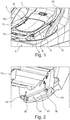
- the base 1 (compare Figures 1 , 3 and 5 ) has a receiving area 2 generally formed on its upper side.
- this receiving area 2 is formed in a turntable 3, which is arranged on a base body 4 of the base 1 so that it can be rotated relative to this base body 4 about an axis of rotation running transversely to the receiving area 2 .
- a central section is formed so as to be curved in the manner of a trough.
- a corresponding central section of the child seat 13 can be placed there.
- To the side of this central section there are strips 5 which are oriented essentially parallel to one another.
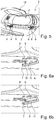
- receiving sections 7 are formed for receiving a holding means on the child seat 13 in a manner to be described in more detail below. These receiving sections 7 are for example in the Figure 5 and - especially good - in the Figures 6a and 6b to recognize. Also in the Figures 6a and 6b It can be clearly seen that a locking element 8 is arranged in each of the receiving openings 6, which is connected to the base 1 in a block-like or strip-like manner at one longitudinal end so as to be pivotable. The locking elements 8 have, on a surface exposed to the receiving area 2, a sliding surface 9 which is straight and flat.
- the locking element 8 is pivoted so far into the receiving opening 6 that it is arranged with its sliding surface 9 parallel to the insertion bevel 11 and is aligned with it.
- a stop can be provided in the depth of the receiving opening 6 or on another section in the base 1, which prevents a further pivoting movement of the locking element 8 into the receiving opening 6.
- An actuating mechanism provided with an actuating element 12, the further details of which are not shown here, allows the locking elements 8 to be displaced from the position shown in FIG Figure 6a
- the locking elements 8 are pretensioned into the locking position shown in FIG. 6a by means of spring elements and spring tensions applied by them, and can be moved into the locking position shown in FIG Figure 6b
- the insertion and release position shown can be shifted, but can also pivot automatically and against the spring force into the insertion and release position by simply applying pressure or a weight force to the sliding surface 9.
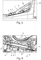
- a safety bracket 18 fixed on the base 1, more precisely on the turntable 3, can be seen which, starting from approximately one central position of the turntable 3 extends ascending upwards, at the same time surrounds the turntable 3 and the receiving area 2 arranged thereon in an arc-shaped manner by approximately 180 °.
- This safety bar 18 is guided in the manner of a railing and is formed from a dimensionally stable material, in particular a metal, such as aluminum or steel, or a dimensionally stable plastic, such as in particular a fiber-reinforced plastic material.
- the base 1 is formed in its base body 4 with a raised section 19 with which the base 1 can be supported against the seat or bench back in an arrangement on a seat or a bench of a motor vehicle, in particular to absorb torques as they can occur in the event of an impact.
- a child seat 13 of the child seat system according to the invention is shown in detail in FIG Figure 2 shown.
- a connection area 14 can be seen with which the child seat 13 is arranged in the receiving area 2 of the base 1 for connecting the child seat 13 to the base 1.
- a front and a To recognize rear position two retaining brackets 15, each having a section 16 with a rod-shaped course.
- the retaining brackets 15 with the sections 16 form retaining means which are provided in the connection area 14 of the child seat.
- the cross section of the retaining bracket 15 is circular in this exemplary embodiment shown, in particular in the section 16.
- the child seat 13 can be a baby seat or a child carrier.
- other types of child seats are also possible, for example a toddler seat, with an analog connection area 14 with retaining means in the form of the retaining bracket 15.
- FIG. 4 a section of the child seat system according to the invention with the child seat 13 is shown in a longitudinal sectional view as it is fixed to the base 1 and connected to the base 1. It can be seen here that the sections 16 of the retaining clips 15 are inserted into the receiving openings 6 and inserted into the receiving sections 7, the locking elements 8 being in the locking position and the front edges 10 of the sections 16 of the retaining clips 15 in the receiving sections Hold 7 and lock it there.
- the locking elements 8 are shifted back into the insertion and release position, so that the sections 16 of the retaining brackets 15 move in the opposite direction along the sliding surfaces 9 of the locking elements 8, the bevels can slide up and out of the receiving openings number 6, so that the child seat 13 can be released from the lock with the base 1 by a pulling movement and then lifted off the base 1.
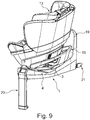
- the child seat system is a child safety seat for a motor vehicle.
- a support leg 20 is formed on the base 1, which is used in a manner known per se to support the base against the floor of the footwell of a motor vehicle in order to prevent the base from "submerging" in the event of an impact and the torques triggered thereby.
- the base also has Isofix claws 21 with which it can be fixed, likewise in a known manner, to corresponding retaining brackets of the vehicle seat system.
- Figure 8 the child seat system is off Figure 7 shown in an installation position in which the child seat 13 is already connected and locked to the base 1, but in which the turntable 3 of the base 1 is rotated by 90 ° with respect to the base body 2 so that the child seat sits laterally on the base 1 .
- the turntable 3 on the base 1 makes it easier for a child to be placed in the child seat 13.
- the base 1 is fixed with its base 4 by means of the Isofix claws 21 on a vehicle seat or a vehicle rear seat of the motor vehicle, it can be turned by turning of the turntable 3 can be achieved in such a way that, for example, a child can be inserted into the child seat 13 oriented in a longitudinal direction through a passenger door or a rear door of the motor vehicle. If the child then sits correctly in the child seat 13 and is buckled up there, the child seat 13 can be swiveled back on the turntable 3 into the position shown in FIG Figure 7 Use position shown and can then be locked in this basic position.
- the child seat 13 can also be placed on the base 1 and connected to it.
- Figure 9 in which the child seat 13 is deposited with the connection area 14 on the receiving area 2 of the base 1, which is formed on the rotary plate 3, but is not yet connected to the base 1 in a locked manner.
- the child seat 13 is then pushed with the sections 16 of the retaining bracket 15 onto the sliding surfaces 9 of the locking elements 8, so that the sections 16 then slide into the receiving sections 7 in the manner described above and then through the into the locking position forced back locking elements 8 are retained and locked there in the manner described above.
- the child seat 13 can also be placed on the base 1 with a child or baby already inserted or placed in the child seat 13, looking towards the person using the child seat 13, and can also already be locked to it. Then the turntable 3 is rotated back into the position of use in which the child is then as in Figure 7 shown facing in the direction of travel or also, in a different constellation, in particular with a different child seat, for example in the form of a baby carrier, is oriented against the direction of travel, depending on the installation requirements of the child seat 13.
- the safety bar 18 can also be clearly seen again. It can also be seen here that it surrounds the child seat 13 like a railing and offers additional protection. In particular, the safety bar 18 helps to prevent the child seat 13 from detaching from the base 1 in the event of an impact by helping to absorb the impact energy and by holding back the child seat 13, which is deliberately deformed at this point under an impact.
Abstract
Offenbart wird ein Kindersitzsystem mit einer Basis (1) und wenigstens einem mit der Basis (1) verriegelbar verbindbaren Kindersitz. Die Basis (1) weist in einem Aufnahmebereich (2) angeordnete Verriegelungsmittel auf. Der Kindersitz weist in einem Anschlussbereich angeordnete Haltemittel auf für eine lösbar verriegelbare Aufnahme in den Verriegelungsmitteln der Basis (1), wenn der Kindersitz mit seinem Anschlussbereich an dem Aufnahmebereich (2) der Basis (1) zur Anlage gebracht wird. Die Haltemittel weisen wenigstens ein einen stabförmigen Abschnitt aufweisendes Halteelement auf. Die Verriegelungsmittel weisen wenigstens eine, ausgehend von einer in dem Aufnahmebereich (2) exponiert liegenden Oberfläche in die Basis (1) hinein führende Aufnahmeöffnung (6) zum Einführen des Halteelements sowie ein Verriegelungselement (8) zum Verriegeln des Halteelements in der Aufnahmeöffnung (8) auf. Das Kindersitzsystem zeichnet sich dadurch aus, dass das Verriegelungselement (8) im Bereich der Aufnahmeöffnung (6) zwischen einer Einführ- und Freigabestellung und einer Riegelstellung verlagerbar an der Basis (1) festgelegt ist und eine ebene Gleitoberfläche (9) aufweist. Weiterhin ist in der Aufnahmeöffnung (6) ein Aufnahmeabschnitt zum Aufnehmen des stabförmigen Abschnitts des Halteelements ausgebildet, in dem der stabförmige Abschnitt des Halteelements durch das in der Riegelstellung befindliche Verriegelungselement (8) verriegelnd gefangen ist. Schließlich bildet das Verriegelungselement (8) in der Einführ- und Freigabestellung mit seiner ebenen Gleitoberfläche (9) eine Gleitebene, die eine Führung zum Einführen des stabförmigen Abschnitts des Halteelements in den Aufnahmeabschnitt bildet.Disclosed is a child seat system with a base (1) and at least one child seat which can be lockably connected to the base (1). The base (1) has locking means arranged in a receiving area (2). The child seat has holding means arranged in a connection area for a releasably lockable receptacle in the locking means of the base (1) when the child seat with its connection area is brought into contact with the receptacle area (2) of the base (1). The holding means have at least one holding element having a rod-shaped section. The locking means have at least one receiving opening (6) for inserting the holding element, starting from a surface exposed in the receiving area (2), leading into the base (1) and a locking element (8) for locking the holding element in the receiving opening (8) on. The child seat system is characterized in that the locking element (8) is fixed on the base (1) so as to be displaceable between an insertion and release position and a locking position in the area of the receiving opening (6) and has a flat sliding surface (9). Furthermore, a receiving section for receiving the rod-shaped section of the retaining element is formed in the receiving opening (6), in which the rod-shaped section of the retaining element is locked by the locking element (8) in the locking position. Finally, in the insertion and release position, the locking element (8) with its flat sliding surface (9) forms a sliding plane which forms a guide for inserting the rod-shaped section of the holding element into the receiving section.
Description
Die Erfindung betrifft ein Kindersitzsystem mit einer Basis und wenigstens einem mit der Basis verriegelbar verbindbaren Kindersitz mit den Merkmalen des Oberbegriffs des Anspruchs 1.The invention relates to a child seat system with a base and at least one child seat which can be locked to the base and which has the features of the preamble of
Kindersitzsysteme, die eine Basis und wenigstens einen mit der Basis verriegelbar verbindbaren Kindersitz aufweisen, sind aus dem Stand der Technik allgemein bekannt. Sie können - und werden dies vielfach auch - insbesondere im Bereich der Kindersicherheitssitze für Kraftfahrzeuge eingesetzt. So kann zum Beispiel die Basis mit Halteklauen aufweisenden Isofix-Anschlussstreben verbunden sein, mittels derer sie mit entsprechenden, an einem Rahmen einer Fahrzeugbank oder eines Fahrzeugsitzes festgelegten Isofix-Anschlussbügeln lösbar verbunden werden kann. Auch ist es bekannt, eine solche Basis mittels eines in dem Kraftfahrzeug vorhandenen Sicherheitsgurtes an einer Sitzfläche, auf der die Basis aufgesetzt wird, zu fixieren.Child seat systems which have a base and at least one child seat which can be lockably connected to the base are generally known from the prior art. They can - and often are - used in particular in the field of child safety seats for motor vehicles. For example, the base can be connected to Isofix connecting struts with retaining claws, by means of which it can be detachably connected to corresponding Isofix connecting brackets fixed to a frame of a vehicle bench or a vehicle seat. It is also known to fix such a base by means of a seat belt present in the motor vehicle on a seat surface on which the base is placed.
Auf einer solchen Basis kann nun ein eigentlicher Kindersitz aufgesetzt und mit der Basis lösbar verbunden werden. Hierzu weist die Basis in einem Aufnahmebereich angeordnete Verriegelungsmittel auf und sind an dem Kindersitz in einem Anschlussbereich Haltemittel angeordnet, die für eine lösbar verriegelbare Aufnahme in den Verriegelungsmitteln der Basis ausgebildet sind, wenn der Kindersitz mit einem Anschlussbereich an dem Aufnahmebereich der Basis zur Anlage gebracht wird.An actual child seat can now be placed on such a base and releasably connected to the base. For this purpose, the base has locking means arranged in a receiving area and holding means are arranged on the child seat in a connection area, which are designed for a releasably lockable receiving in the locking means of the base when the Child seat is brought to bear with a connection area on the receiving area of the base.
Der Kindersitz des Kindersitzsystems kann beispielsweise eine bereits für Neugeborene und auch für schon ältere Babys verwendbare Kindersitzschale, auch Babyschale genannt, sein, in der das Baby in einer im wesentlichen liegenden Position gehalten wird. Der Kindersitz kann aber auch ebenso gut ein Kleinkindsitz sein, in dem das Kind mit fortgeschrittenem Alter bereits aufrecht sitzen kann. Derartige Kleinkindsitze können von Kindern genutzt werden, bis diese in Kraftfahrzeugen auch ohne gesondert angeordneten Kindersicherheitssitz platziert werden und sitzen können.The child seat of the child seat system can, for example, be a child seat shell, also called a baby shell, which can already be used for newborns and also for older babies, in which the baby is held in an essentially lying position. The child seat can also be a toddler seat in which the child can sit upright at an advanced age. Such toddler seats can be used by children until they can be placed and sit in motor vehicles without a separately arranged child safety seat.
Es sind auch Kindersitzsysteme bekannt, die mehr als einen Kindersitz zusammen mit einer einzigen Basis umfassen, wobei die Kindersitze jeweils mit der einen Basis verbunden werden können. So können die Nutzer das Kindersitzsystem im Gebrauch anpassen auf die Größe bzw. das Alter des Kindes, welches in dem Kindersitzsystem, genau einem Kindersitz, Platz nehmen und darin sitzend oder auch liegend zum Beispiel befördert werden soll.Child seat systems are also known which comprise more than one child seat together with a single base, which child seats can each be connected to the one base. In this way, users can adapt the child seat system in use to the size or age of the child who is to be seated in the child seat system, precisely a child seat, and is to be transported while sitting or lying down, for example.
Bei den bekannten Kindersitzsystemen weisen die Verriegelungsmittel häufig Hakenelemente auf, die um eine deutlich von einer Oberfläche des Aufnahmebereichs der Basis in Richtung des Inneren der Basis versetzt angeordnete Drehachse verdreht, bzw. verschwenkt oder verkippt werden können zwischen einer Riegelstellung und einer Freigabestellung. Die Haltemittel an dem Kindersitz umfassen dabei stangen- oder stabförmige Elemente, häufig Metallstangen, die zum Verbinden des Kindersitzes mit der Basis in den Bereich der Hakenelemente verbracht werden und an denen die Hakenelemente in der Riegelstellung einhaken und so die stangen- oder stabförmigen Elemente zurück- und damit den Kindersitz auf der Basis festhalten. Derartige Lösungen sind beispielsweise in der
Das Problem bei diesen Lösungen ist, dass der Kindersitz von einem Bediener in der Regel sehr präzise und von oben her mit dem Anschlussbereich auf den Aufnahmebereich der Basis aufgesetzt werden muss, sodass die stangen- oder stabförmigen Elemente an dem Kindersitz hinter die in die Freigabestellung bewegten Hakenelemente gelangen und von den dann in die Riegelstellung bewegten Hakenelementen zurückgehalten werden können. Insbesondere dann, wenn - zum Beispiel im Falle einer Babyschale - der Kindersitz nicht losgelöst, sondern schon mit einem darin liegenden oder sitzenden Baby oder Kleinkind auf die Basis aufgesetzt und mit dieser verbunden werden soll, kann ein solches Verbinden erhebliche Anstrengung verursachen, wenn zum Beispiel die Mutter des Kindes den Kindersitz mit dem darin liegenden oder sitzenden Kind anheben und von oben her zielgenau auf die Basis aufsetzen muss.The problem with these solutions is that the child seat has to be placed very precisely by an operator and from above with the connection area on the receiving area of the base, so that the rod or Rod-shaped elements on the child seat get behind the hook elements moved into the release position and can be held back by the hook elements then moved into the locking position. In particular, if - for example in the case of a baby seat - the child seat is not to be detached, but is to be placed on the base with a baby or toddler lying or sitting in it and connected to it, such a connection can cause considerable effort, for example if the mother of the child must lift the child seat with the child lying or sitting in it and place it precisely on the base from above.
Hier setzt die Erfindung an und sucht Abhilfe zu schaffen, indem ein Kindersitzsystem der eingangs genannten Art angegeben werden soll, welches ein in der Bedienung vereinfachtes Aufsetzen und Verbinden eines Kindersitzes auf die und mit der Basis erlaubt.This is where the invention comes in and seeks to remedy the situation by specifying a child seat system of the type mentioned at the outset which allows a child seat to be placed on and connected to the base in a simplified manner in terms of operation.
Diese Aufgabe wird erfindungsgemäß gelöst mit einem Kindersitzsystem mit den Merkmalen des Patentanspruchs 1. Vorteilhafte Weiterbildungen eines solchen Kindersitzsystems sind in den abhängigen Ansprüchen 2 bis 15 angegeben.This object is achieved according to the invention with a child seat system having the features of
Ein erfindungsgemäßes Kindersitzsystem hat zunächst, wie aus dem Stand der Technik umfangreich bekannt, eine Basis und wenigstens einen mit der Basis verriegelbar verbindbaren Kindersitz. Die Basis weist in einem Aufnahmebereich angeordnete Verriegelungsmittel auf, und der Kindersitz verfügt über in einem Anschlussbereich angeordnete Haltemittel. Die Haltemittel sind für eine lösbar verriegelbare Aufnahme in den Verbindungsmitteln der Basis ausgebildet, wenn der Kindersitz mit seinem Anschlussbereich an dem Aufnahmebereich der Basis zur Anlage gebracht wird. Die Haltemittel weisen wenigstens ein einen stabförmigen Abschnitt aufweisendes Halteelement auf. Die Verriegelungsmittel weisen wiederum wenigstens eine ausgehend von einer in dem Aufnahmebereich exponiert liegenden Oberfläche in die Basis hineinführende Aufnahmeöffnung zum Einführen des Haltemittels auf. Die Verriegelungsmittel weisen ferner ein Verriegelungselement zum Verriegeln des Halteelements in der Aufnahmeöffnung auf.As is well known from the prior art, a child seat system according to the invention initially has a base and at least one child seat which can be locked to the base. The base has locking means arranged in a receiving area, and the child seat has holding means arranged in a connection area. The holding means are designed for a releasably lockable receptacle in the connecting means of the base when the child seat is brought into contact with its connection area on the receiving area of the base. The holding means have at least one holding element having a rod-shaped section. The locking means in turn have at least one receiving opening, starting from a surface exposed in the receiving area, leading into the base for introducing the holding means. The locking means also have a locking element for locking the holding element in the receiving opening.
In erfindungsgemäßer Weise ist das Verriegelungselement im Bereich der Aufnahmeöffnung zwischen einer Einführ- und Freigabestellung und einer Riegelstellung verlagerbar an der Basis festgelegt und weist eine ebene Gleitoberfläche auf. Die ebene Gleitoberfläche ist insbesondere planar gestaltet und kann insbesondere flach und ohne jede Krümmung verlaufen. Erfindungsgemäß ist weiterhin in der Aufnahmeöffnung ein Aufnahmeabschnitt zum Aufnehmen des stabförmigen Abschnitts des Halteelements ausgebildet, in dem der stabförmige Abschnitt des Halteelements durch das Verriegelungselement verriegelnd gefangen ist, wenn sich dieses in der Riegelstellung befindet. Das Verriegelungselement bildet in der Einführ- und Freigabestellung mit seiner ebenen Gleitoberfläche eine Gleitebene, die eine Führung zum Einführen des stabförmigen Abschnitts des Halteelements in den Aufnahmeabschnitt bildet.In a manner according to the invention, the locking element is fixed on the base so as to be displaceable between an insertion and release position and a locking position in the region of the receiving opening and has a flat sliding surface. The flat sliding surface is designed in particular planar and can in particular run flat and without any curvature. According to the invention, a receiving section for receiving the rod-shaped section of the retaining element is also formed in the receiving opening, in which the rod-shaped section of the retaining element is locked by the locking element when it is in the locking position. In the insertion and release position, the locking element forms with its flat sliding surface a sliding plane which forms a guide for inserting the rod-shaped section of the holding element into the receiving section.
Durch diese erfindungsgemäße Ausgestaltung muss der Kindersitz zum Verbinden mit der Basis nicht exakt von oben her so auf die Basis aufgesetzt werden, dass die Haltemittel mit den Verriegelungsmitteln in übereinstimmender Position angeordnet sind. Vielmehr kann der Kindersitz mit seinem Anschlussbereich auch so auf dem Aufnahmebereich der Basis abgesetzt werden, dass hier ein Versatz zwischen Verriegelungsmitteln und Haltemitteln gegeben ist, kann der Kindersitz dann durch Verschieben mit seinem Anschlussbereich entlang des Aufnahmebereichs so bewegt werden, dass die Haltemittel, insbesondere der stabförmige Abschnitt des Halteelements, auf der ebenen Gleitoberfläche des Verriegelungselements aufliegen und in die Aufnahmeöffnung hineingleiten bis der stabförmige Abschnitt des Halteelements in dem Aufnahmeabschnitt zu liegen kommt und dort insbesondere an einem vorteilhafterweise dort angeordneten Anschlag anschlägt. Zum Verriegeln der so geschaffenen Verbindung zwischen Kindersitz und Basis wird nun das Verriegelungselement in die Riegelstellung verschwenkt, sodass der Kindersitz sicher und fest an der Basis gehalten ist. Durch diese Möglichkeit einer auch versetzt aufgesetzten Anordnung und eines Hineingleitens des Kindersitzes in die Riegelposition auf der Basis kann zum Beispiel eine Mutter einen Kindersitz des Systems in Form einer Babyschale in grober Ausrichtung auf der Basis abstellen und dann durch Verschieben auf der Basis besorgen, dass der stabförmige Abschnitt des Halteelements in die Aufnahmeöffnung und bis in den Aufnahmeabschnitt hineingleitet und der Kindersitz an der Basis verriegelt werden kann. Der Kindersitz muss nun nicht mehr genau auf der Basis abgesetzt und hierzu gegebenenfalls mehrfach angehoben oder langandauernd und zielend oberhalb der Basis gehalten werden.As a result of this configuration according to the invention, the child seat does not have to be placed on the base exactly from above in order to be connected to the base in such a way that the holding means with the locking means are arranged in a matching position. Rather, the child seat with its connection area can also be set down on the receiving area of the base in such a way that there is an offset between the locking means and the holding means Rod-shaped section of the holding element rest on the flat sliding surface of the locking element and slide into the receiving opening until the rod-shaped section of the holding element comes to rest in the receiving section and strikes there in particular against a stop advantageously arranged there. To lock the connection created in this way between the child seat and the base, the locking element is now pivoted into the locking position so that the child seat is held securely and firmly on the base. This possibility of an offset arrangement and the sliding of the child seat into the locking position on the base, for example, allows a mother to place a child seat of the system in the form of a baby seat in a rough orientation on the base and then move it on the base to ensure that the Rod-shaped section of the holding element into the receiving opening and into the Receiving section slides in and the child seat can be locked to the base. The child seat now no longer has to be set down exactly on the base and, for this purpose, raised several times or held over the base for a long time and aimed.
Das Verriegelungselement kann zum Beispiel leistenförmig oder brettartig gebildet sein und nach Art einer Falltür die Aufnahmeöffnung in der Riegelstellung überdecken, in der Einführ- und Freigabestellung in die Aufnahmeöffnung hinein tauchen und dabei die Gleitebene bilden, über die der stabförmige Abschnitt des Halteelements in die Aufnahmeöffnung hinein und bis zu dem Aufnahmeabschnitt rutscht oder gleitet.The locking element can, for example, be in the form of a strip or board and cover the receiving opening in the locking position like a trap door, plunge into the receiving opening in the insertion and release position and thereby form the sliding plane over which the rod-shaped section of the holding element enters the receiving opening and slides or slides up to the receiving portion.
Um das Verriegelungselement aus der Riegelstellung in die Einführ- und Freigabestellung bewegen zu können, kann insbesondere an der Basis ein Betätigungsmechanismus angeordnet sein. Dieser Betätigungsmechanismus kann - muss dies allerdings nicht - auch für ein Verlagern des Verriegelungselements aus der Einführ- und Freigabestellung in die Riegelstellung verwendbar gestaltet sein. Es ist aber ebenso gut auch möglich und in einer vorteilhaften Ausgestaltung der Erfindung vorgesehen, dass das Verriegelungselement federbelastet in die Riegelstellung gezwungen ist. Hierfür kann ein oder können mehrere geeignete Federelemente oder dergleichen vorgesehen sein.In order to be able to move the locking element from the locking position into the insertion and release position, an actuating mechanism can in particular be arranged on the base. This actuating mechanism can - but does not have to - be designed so that it can also be used for displacing the locking element from the insertion and release position into the locking position. However, it is just as well possible and provided in an advantageous embodiment of the invention that the locking element is forced into the locking position in a spring-loaded manner. One or more suitable spring elements or the like can be provided for this purpose.
Mit Vorteil kann weiterhin vorgesehen sein, dass die Aufnahmeöffnung mit einer Einführschräge versehen ist, die ausgehend von der in dem Aufnahmebereich exponiert liegenden Oberfläche schräg in die Basis hinein verläuft und an deren Ende der Aufnahmeabschnitt liegt. Diese Einführschräge ist dann insbesondere so gestaltet, dass auf ihr der stabförmige Abschnitt des Halteelements auf einer Oberkante oder Oberfläche gleiten kann, wenn dieser in die Aufnahmeöffnung hinein überführt wird. Diese Einführschräge kann zum Beispiel materialverstärkt gebildet sein, zum Beispiel durch Einlage einer Metallleiste, um an dieser stark beanspruchten Stelle einem Verschleiß vorzubeugen. Wenn eine solche Einführschräge vorgesehen ist, kann insbesondere und mit Vorteil vorgesehen sein, dass das Verriegelungselement in der Einführ- und Freigabestellung mit der Gleitoberfläche im Wesentlichen bündig parallel zu einer Oberkante oder Oberfläche der Einführschräge ausgerichtet ist. Durch diese Maßnahme bilden die Gleitoberfläche des Verriegelungselements und die Oberkante oder Oberfläche der Einführschräge gemeinsam eine Führungsebene, entlang derer der stabförmige Abschnitt des Halteelements in die Aufnahmeöffnung hineingleiten kann bis zu dem Aufnahmeabschnitt.It can also advantageously be provided that the receiving opening is provided with an insertion bevel which, starting from the surface exposed in the receiving area, runs obliquely into the base and at the end of which the receiving section lies. This lead-in bevel is then designed in particular so that the rod-shaped section of the holding element can slide on it on an upper edge or surface when it is transferred into the receiving opening. This lead-in bevel can, for example, be made of reinforced material, for example by inserting a metal strip in order to prevent wear at this highly stressed point. If such an insertion bevel is provided, it can in particular and advantageously be provided that the locking element in the insertion and release position with the Sliding surface is aligned essentially flush parallel to an upper edge or surface of the lead-in bevel. As a result of this measure, the sliding surface of the locking element and the upper edge or surface of the insertion bevel jointly form a guide plane along which the rod-shaped section of the holding element can slide into the receiving opening up to the receiving section.
Mit Vorteil kann das Verriegelungselement in der Riegelstellung mit der Gleitoberfläche im Wesentlichen bündig mit der in dem Aufnahmebereich exponiert liegenden Oberfläche ausgerichtet sein. Dies ist insbesondere deshalb von Vorteil, da so der auf die Basis aufgesetzte Kindersitz bei einem Verschieben ohne Versatz auf die Oberfläche des Verriegelungselementes in der Riegelstellung auflaufen und dann, insbesondere wenn das Verriegelungselement durch Federkraft in die Riegelstellung vorgespannt ist, dieses gegen die Federkraft in Richtung in die Aufnahmeöffnung hinein drücken und dann auf der Gleitoberfläche die Aufnahmeöffnung hineingleiten kann bis zu dem und in den Aufnahmeabschnitt.Advantageously, in the locking position with the sliding surface, the locking element can be aligned essentially flush with the surface exposed in the receiving area. This is particularly advantageous because the child seat placed on the base will run onto the surface of the locking element in the locking position when it is moved without offset and then, in particular when the locking element is biased into the locking position by spring force, it counteracts the spring force in the direction Press into the receiving opening and then slide the receiving opening on the sliding surface up to and into the receiving section.
Mit Vorteil kann das Verriegelungselement im Bereich eines Stirnendes der Aufnahmeöffnung um eine Schwenkachse schwenkbar an der Basis festgelegt sein. Diese Schwenkachse kann mit besonderem Vorteil nahe der oder an der in dem Aufnahmebereich exponiert liegenden Oberfläche liegen, sodass das Verriegelungselement oberflächennah, insbesondere bündig mit der Oberfläche gelagert sein kann. Ein solches Verriegelungselement kann dann weiterhin und insbesondere gemäß einer vorteilhaften Weiterbildung der Erfindung an einer der Schwenkachse gegenüberliegenden Kante einen Anschlag aufweisen, der in der Riegelstellung des Verriegelungselements den stabförmigen Abschnitt des Halteelements in dem Aufnahmeabschnitt hält. Ein solcher Anschlag kann zum Beispiel ein quer zu der Gleitoberfläche geführter, sich in Richtung der Aufnahmeöffnung erstreckender Absatz oder Fortsatz sein, der in der Riegelstellung die Tiefe der Aufnahmeöffnung überbrückt bis hin zu dem Aufnahmeabschnitt, den dieser Absatz oder Fortsatz dann in Richtung der freien Aufnahmeöffnung versperrt und so den darin befindlichen stabförmigen Abschnitt des Halteelements dort verriegelt und fixiert.The locking element can advantageously be fixed on the base in the region of a front end of the receiving opening so as to be pivotable about a pivot axis. This pivot axis can be located close to or on the exposed surface in the receiving area, so that the locking element can be mounted close to the surface, in particular flush with the surface. Such a locking element can then furthermore, and in particular according to an advantageous development of the invention, have a stop on an edge opposite the pivot axis which holds the rod-shaped section of the holding element in the receiving section in the locking position of the locking element. Such a stop can be, for example, a shoulder or extension that extends transversely to the sliding surface and extends in the direction of the receiving opening, which in the locking position bridges the depth of the receiving opening up to the receiving section, which this shoulder or extension then in the direction of the free receiving opening blocked and so the rod-shaped section of the holding element located therein is locked and fixed there.
Das Halteelement kann insbesondere als ein in dem Anschlussbereich an dem Kindersitz gebildeter Haltebügel gebildet sein, der in Abschnitt den stabförmigen Abschnitt aufweist. Grundsätzlich sind zwar auch durchgehende Stangen o. ä. Konstruktionen denkbar. Derartige Haltebügel, wie sie hier mit besonderem Vorteil vorgeschlagen werden, eignen sich aber besonders deshalb, da diese einzelnen in die jeweilige Aufnahmeöffnung eingebracht werden können und es damit nicht erforderlich ist, die Aufnahmeöffnung für den Durchtritt einer durchgehenden Stange etwa seitlich zu öffnen. Dies erlaubt dann wiederum eine stabilere Konstruktion.The holding element can in particular be formed as a holding bracket which is formed in the connection area on the child seat and which has the rod-shaped section in section. In principle, continuous rods or similar constructions are also conceivable. Such retaining brackets, as proposed here with particular advantage, are particularly suitable because they can be introduced individually into the respective receiving opening and it is therefore not necessary to open the receiving opening approximately to the side for a continuous rod to pass through. This in turn allows a more stable construction.
Gemäß einer weiteren vorteilhaften Weiterbildung des erfindungsgemäßen Kindersitzsystems kann der Aufnahmebereich in einem relativ zu einem Grundkörper der Basis um wenigstens 45°, vorzugsweise um wenigstens 90°, rotierbaren Drehteller gebildet sein. Dieser Drehteller kann dann zum Beispiel mittels einer Verriegelung in einer Einbaudrehstellung mit einer für den Gebrauch des auf der Basis montierten Kindersitzes vorgesehenen Stellung verriegelbar sein. Gerade dann, wenn das Erfindungsgemäße Kindersitzsystem zum Einsatz in einem Kraftfahrzeug gedacht ist, kann ein solcher Drehteller das Einsetzen des Kindersitzes noch einmal erleichtern. So kann der Drehteller beispielsweise um 90° rotiert werden, sodass der Kindersitz zum Beispiel von einer Hecktür des Fahrzeuges aus einfach in dieser um 90° verdrehten Stellung eingesetzt und in einer wie oben beschriebenen Weise mit der Basis verbunden werden kann. Ist der Kindersitz dann mit der Basis verbunden und verriegelt, kann der Drehteller zurückgedreht werden in die Gebrauchsstellung, in der der Kindersitz mit einer Front in Fahrtrichtung oder entgegen der Fahrtrichtung orientiert ist, und kann der Drehteller in dieser Position verrastet werden.According to a further advantageous development of the child seat system according to the invention, the receiving area can be formed in a turntable which can be rotated by at least 45 °, preferably by at least 90 °, relative to a base body of the base. This turntable can then be locked, for example by means of a lock, in an installed rotary position with a position provided for the use of the child seat mounted on the base. Especially when the child seat system according to the invention is intended for use in a motor vehicle, such a turntable can once again facilitate the insertion of the child seat. For example, the turntable can be rotated by 90 ° so that the child seat, for example, can be easily inserted from a rear door of the vehicle in this position rotated by 90 ° and connected to the base in a manner as described above. If the child seat is then connected to the base and locked, the turntable can be turned back into the position of use in which the child seat is oriented with a front in the direction of travel or against the direction of travel, and the turntable can be locked in this position.
Mit Vorteil kann weiterhin an der Basis ein von der Basis, insbesondere aufwärtsgerichtet, vorstehender Sicherheitsbügel angeordnet sein. Dieser Sicherheitsbügel kann vorzugsweise in dem oder angrenzend an den Aufnahmebereich an der Basis festgelegt sein. Er kann weiterhin insbesondere an einem wie vorstehend erläuterten Drehteller der Basis angeordnet sein. Der Sicherheitsbügel kann mit Vorteil zu einer Außenseite der Basis aufsteigen und einen Abschnitt von wenigstens 100°, vorzugsweise von wenigstens 140°, insbesondere von wenigstens 180° einfassen. Er besteht mit Vorteil aus einem formstabilen Material wie einem Metall oder einem stabilen, insbesondere verstärkten, wie faserverstärkten, Kunststoff. Der Sicherheitsbügel kann dabei mit Vorteil so angeordnet sein, dass er mit einem vorgegebenen Abstand einen Teil eines Kindersitzes umgreift. Er ist insbesondere in einer Einbau- und Gebrauchslage des Kindersitzes in oder entgegen der Fahrtrichtung orientiert. Dieser Sicherheitsbügel dient dazu, bei einem als Kindersicherheitssitz in einem Fahrzeug verwendeten Kindersitzsystem nach der Erfindung bei einem Aufprall den Kindersitz abzufangen und Aufprallenergie aufzunehmen und insbesondere ein Ablösen des Kindersitzes von der Basis zu verhindern. Insbesondere kann z.B. eine Babyschale mit Kunststoffwänden, die sich bei einem Aufprall durch die auftretende Energie bewusst verformen sollen zur Dissipation dieser Energie, sich bis zu dem Sicherheitsbügel ausdehnen und wird dann dort gefangen und gehalten. Auch bietet der Sicherheitsbügel einen weiteren Seitenaufprallschutz.A safety bar protruding from the base, in particular pointing upwards, can also advantageously be arranged on the base. This safety bar can preferably be fixed in or adjacent to the receiving area on the base. It can furthermore be arranged in particular on a turntable of the base as explained above. The safety bar can advantageously rise to an outside of the base and a section of at least 100 °, preferably at least 140 °, in particular at least 180 °. It advantageously consists of a dimensionally stable material such as a metal or a stable, in particular reinforced, such as fiber-reinforced plastic. The safety bar can advantageously be arranged in such a way that it encompasses a part of a child seat at a predetermined distance. In particular, when the child seat is installed and in use, it is oriented in or against the direction of travel. In a child seat system according to the invention used as a child safety seat in a vehicle, this safety bar serves to intercept the child seat in the event of an impact and to absorb impact energy and in particular to prevent the child seat from becoming detached from the base. In particular, for example, a baby seat with plastic walls, which are to be deliberately deformed in the event of an impact due to the occurring energy, in order to dissipate this energy, can expand up to the safety bar and is then caught and held there. The safety bar also offers additional side impact protection.
Auch wenn es grundsätzlich möglich ist, dass die Verriegelungsmittel nur ein Verriegelungselement und eine Aufnahmeöffnung umfassen und dass die Haltemittel lediglich ein Halteelement beinhalten, wird doch bevorzugt, dass derer mehrere vorhanden sind in unterschiedlichen Positionen, wobei die Positionen der Haltemittel zu den Positionen der Verriegelungsmittel korrespondierend angeordnet sind. Auf diese Weise wird ein sicherer Halt des Kindersitzes an der Basis erhalten. Mit Vorteil sollte hier ein möglicher Betätigungsmechanismus dann gleichzeitig auf alle Verriegelungselemente wirken, um diese gleichzeitig und mit einem Bedienungshandgriff in die Einführ- und Freigabestellung verbringen zu können. Eine solche Anordnung mit mehreren an unterschiedlichen Positionen angeordneten Verriegelungsmitteln und Haltemitteln kann insbesondere so gebildet sein, dass diese jeweils vier an Eckpunkten von zueinander kongruenten Rechtecken bzw. Quadraten angeordnete Haltemittel bzw. Verriegelungsmittel aufweist. Eine solche Anordnung hat sich als besonders stabil und zugleich einfach zu bedienen und umzusetzen erwiesen.Even if it is basically possible that the locking means comprise only one locking element and one receiving opening and that the holding means contain only one holding element, it is preferred that there are several of them in different positions, the positions of the holding means corresponding to the positions of the locking means are arranged. In this way, a secure hold of the child seat on the base is obtained. A possible actuating mechanism should then advantageously act simultaneously on all locking elements in order to be able to bring them into the insertion and release position simultaneously and with one operating handle. Such an arrangement with a plurality of locking means and holding means arranged at different positions can in particular be formed in such a way that it has four holding means or locking means arranged at corner points of mutually congruent rectangles or squares. Such an arrangement has proven to be particularly stable and at the same time easy to use and implement.
Auch das erfindungsgemäße Kindersitzsystem kann mehr als einen, zum Beispiel zwei oder mehr unterschiedlich gestaltete Kindersitze enthalten, zum Beispiel eine Babyschale oder Kindersitzschale und einen Kleinkindsitz. Dem Nutzer können die einzelnen Elemente eines solchen Kindersitzsystems individuell angeboten werden, sodass er die Möglichkeit haben kann, eine Basis und einen für ihn passenden Kindersitz zu erwerben. Er kann aber auch sogleich mehrere Kindersitze in einem System erwerben und dann den für ihn passenden Kindersitz auswählen und mit der Basis verbinden, um ein Kind in den entsprechenden Kindersitz unterzubringen.The child seat system according to the invention can also contain more than one, for example two or more differently designed child seats, for example a baby seat or child seat shell and a toddler seat. The individual elements of such a child seat system can be offered to the user individually so that he can have the opportunity to purchase a base and a child seat that is suitable for him. But he can also purchase several child seats in one system and then select the child seat that is right for him and connect it to the base in order to accommodate a child in the appropriate child seat.
Das erfindungsgemäße Kindersitzsystem kann insbesondere für die Festlegung in einem Kraftfahrzeug ausgelegt sein und einen Kindersitz in Form eines Kindersicherheitssitzes für ein Kraftfahrzeug enthalten, der zum Beispiel eine Gurtanordnung zum Anschnallen eines in dem Kindersitz sitzenden oder liegenden Kindes mit umfasst. Das Kindersitzsystem kann aber auch in einer anderen Weise umgesetzt sein, zum Beispiel als Bestandteil eines Kinderwagens oder eines Kinderkarrens, wobei die Basis dann mit einem Fahrgestell des Kinderwagens oder Kinderkarrens verbunden ist.The child seat system according to the invention can in particular be designed for securing in a motor vehicle and contain a child seat in the form of a child safety seat for a motor vehicle, which includes, for example, a belt arrangement for buckling up a child sitting or lying in the child seat. The child seat system can, however, also be implemented in another way, for example as part of a stroller or a child's cart, the base then being connected to a chassis of the stroller or child's cart.
Weitere Vorteile und Merkmale eines erfindungsgemäßen Kindersitzsystems ergeben sich aus der nachfolgenden Beschreibung eines möglichen Ausführungsbeispiels anhand der beigefügten Figuren. Dabei zeigen:
Figur 1- eine perspektivische Schrägaufsicht auf einen Ausschnitt einer Basis eines erfindungsgemäßen Kindersitzsystems in einem möglichen Ausführungsbeispiel;
Figur 2- eine perspektivische Ansicht schräg von unten auf einen Ausschnitt eines Kindersitzes eines erfindungsgemäßen Kindersitzsystems in dem möglichen Ausführungsbeispiel;
Figur 3- eine schematische Teil-Seitenansicht auf die Basis des Kindersitzsystems;
Figur 4- eine Längsschnittdarstellung durch einen Ausschnitt des Kindersitzsystem mit auf der Basis festgelegtem Kindersitz;
Figur 5- eine Schrägaufsicht auf einen Ausschnitt der Basis mit zwei Verriegelungsmitteln mit je einem in der Riegelstellung und einem in der Einführ- und Freigabestellung befindlichen Verriegelungselement;
Figur 6- in zwei Darstellungen a und b in einer vergrößerten Ansicht von der Seite ein Verriegelungsmittel mit in der Riegelstellung befindlichem Verriegelungselement (
Figur 6a ) und mit in der Einführ- und Freigabestellung befindlichem Verriegelungselement (Figur 6b ); Figur 7- eine perspektivische Ansicht eines Kindersitzsystems mit auf der Basis aufgesetztem und mit der Basis verriegelten Kindersitz in einer Gebrauchsstellung;
Figur 8- eine perspektivische Ansicht eines Kindersitzsystems mit auf der Basis aufgesetztem und mit der Basis verriegelten Kindersitz in einer Einbaustellung; und
Figur 9- eine perspektivische Ansicht eines Kindersitzsystems mit auf der Basis aufgesetztem mit der Basis noch nicht verriegelten Kindersitz in einer Einbaustellung.
- Figure 1
- a perspective oblique view of a section of a base of a child seat system according to the invention in a possible embodiment;
- Figure 2
- a perspective view obliquely from below of a section of a child seat of a child seat system according to the invention in the possible embodiment;
- Figure 3
- a schematic partial side view of the base of the child seat system;
- Figure 4
- a longitudinal section through a section of the child seat system with a child seat fixed on the base;
- Figure 5
- an oblique view of a section of the base with two locking means, each with one in the locking position and one in the insertion and release position;
- Figure 6
- In two representations a and b, in an enlarged view from the side, a locking means with a locking element in the locking position (
Figure 6a ) and with the locking element in the insertion and release position (Figure 6b ); - Figure 7
- a perspective view of a child seat system with a child seat placed on the base and locked to the base in a position of use;
- Figure 8
- a perspective view of a child seat system with a child seat placed on the base and locked to the base in an installed position; and
- Figure 9
- a perspective view of a child seat system with a child seat placed on the base and not yet locked to the base in an installed position.
Nachfolgend wird anhand der Figuren ein mögliches Ausführungsbeispiel für ein erfindungsgemäßes Kindersitzsystem beschrieben und näher erläutert. Die Figuren zeigen dabei, jeweils in Ausschnittdarstellungen, Bestandteile des erfindungsgemäßen Kindersitzsystems und insbesondere solche Strukturen, in denen sich die erfindungswesentlichen Merkmale verkörpern. Die Figuren sind dabei keineswegs als vollständige Konstruktionszeichnungen zu verstehen und auch nicht zwingend maßstabsgerecht.A possible exemplary embodiment for a child seat system according to the invention is described and explained in more detail below with reference to the figures. The figures show, in each case in detail representations, components of the child seat system according to the invention and in particular those structures in which the features essential to the invention are embodied. The figures are by no means to be understood as complete construction drawings and are also not necessarily to scale.
Ein erfindungsgemäßes Kindersitzsystem besteht zunächst aus einer Basis, die in dem gezeigten Ausführungsbeispiel mit dem Bezugszeichen 1 bezeichnet ist, und einem Kindersitz, in dem Ausführungsbeispiel mit dem Bezugszeichen 13 versehen.A child seat system according to the invention consists first of all of a base, which is denoted by the
Der Kindersitz 13 kann auf die Basis 1 aufgesetzt und mit dieser lösbar verbunden und verriegelt werden. Die Basis 1 (vergleiche
In den Aufnahmeöffnungen 6 sind jeweils Aufnahmeabschnitte 7 ausgebildet zum Aufnehmen eines Haltemittels an dem Kindersitz 13 in einer nachfolgend noch näher zu beschreibenden Weise. Diese Aufnahmeabschnitte 7 sind beispielsweise in der
In der wie in
Ein mit einem Betätigungselement 12 versehener Betätigungsmechanismus, der hier in seinen weiteren Einzelheiten nicht näher gezeigt ist, erlaubt ein Verlagern der Verriegelungselemente 8 aus der in
In den
Ein Kindersitz 13 des erfindungsgemäßen Kindersitzsystems ist ausschnittsweise in
In dem gezeigten Ausführungsbeispiel kann der Kindersitz 13 eine Babyschale bzw. Kinderliegeschale sein. Es kommen aber auch andere Arten von Kindersitzen, zum Beispiel ein Kleinkindsitz infrage, mit einem analog ausgebildeten Anschlussbereich 14 mit Haltemitteln in Form der Haltebügel 15.In the exemplary embodiment shown, the
In der
Zum Verbinden des Kindersitzes 13 mit der Basis 1 muss nun nicht der Kindersitz 13 exakt derart über der Basis 1 und deren Aufnahmebereich 2 platziert werden, dass die Abschnitte 16 der Haltebügel 15 genau oberhalb der Aufnahmeöffnungen 6 liegen. Vielmehr kann der Kindersitz 13 auf der Basis 1 mit dem Anschlussbereich 14 dem Aufnahmebereich 2 zugewandt abgesetzt werden und dann durch Verschieben mit den Abschnitten 16 der Haltebügel 15 über die Gleitoberflächen 9 der dann in der Einführ- und Entriegelungsstellung befindlichen Verriegelungselemente 8 auf einer durch diese Elemente gebildeten schiefen Ebene bis in die Aufnahmeabschnitte 7 hineingleiten, wobei dann die Verriegelungselemente 8 getrieben durch die Federkraft zurück in die Riegelstellung gezogen bzw. gedrückt werden und dann mit ihren Vorderkanten 10 die Abschnitte 16 der Haltebügel 15 in den Aufnahmeabschnitten 7 verriegeln. Zum Lösen des Kindersitzes 13 von der Basis 1 wird durch Betätigen des Betätigungselements 12 erreicht, dass die Verriegelungselemente 8 wieder in die Einführ- und Freigabestellung verlagert werden, sodass die Abschnitte 16 der Haltebügel 15 in umgekehrter Richtung entlang der Gleitoberflächen 9 der Verriegelungselemente 8 die Schrägen aufwärts und aus den Aufnahmeöffnungen Ziffer 6 herausgleiten können, sodass der Kindersitz 13 durch eine Zugbewegung aus der Verriegelung mit der Basis 1 gelöst und dann von der Basis 1 abgehoben werden kann.In order to connect the
In dem gezeigten Ausführungsbeispiel ist das Kindersitzsystem ein solches für einen Kindersicherheitssitz für ein Kraftfahrzeug. Dieses ist in den
In
In
In der um 90° verdrehten Position des Drehtellers 3 gegenüber dem Grundkörper 4 der Basis 1 kann der Kindersitz 13 auch auf die Basis 1 aufgesetzt und mit dieser verbunden werden. Gezeigt ist dies in
In den
Aus der vorstehenden Beschreibung sind noch einmal die besonderen Vorteile der erfindungsgemäßen Konstruktion deutlich geworden. Dabei ist aber anzumerken, dass das Ausführungsbeispiel die Erfindung lediglich erläutert, nicht jedoch auf diese konkrete Ausführungsform beschränkt. Es sind weitere Ausgestaltungsvarianten denkbar, die im Rahmen der Erfindung liegen, und die der Fachmann anhand der Ansprüche und der vorstehenden Beschreibung des Ausführungsbeispiels wie auch der voranstehenden allgemeinen Beschreibung konzipieren und umsetzen kann, ohne hierbei erfinderisch tätig werden zu müssen.The particular advantages of the construction according to the invention have once again become clear from the above description. It should be noted, however, that the exemplary embodiment merely explains the invention, but is not limited to this specific embodiment. Further design variants are conceivable which are within the scope of the invention and which the person skilled in the art based on the claims and the above description of the Embodiment as well as the preceding general description can design and implement without having to be inventive.
- 11
- BasisBase
- 22
- AufnahmebereichRecording area
- 33rd
- DrehtellerTurntable
- 44th
- GrundkörperBase body
- 55
- Leistestrip
- 66th
- AufnahmeöffnungReceiving opening
- 77th
- AufnahmeabschnittReceiving section
- 88th
- VerriegelungselementLocking element
- 99
- GleitoberflächeSliding surface
- 1010
- VorderkanteLeading edge
- 1111
- EinführschrägeLead-in bevel
- 1212th
- BetätigungselementActuator
- 1313th
- Kindersitzchild seat
- 1414th
- AnschlussbereichConnection area
- 1515th
- HaltebügelRetaining bracket
- 1616
- Abschnittsection
- 1717th
- Absatzunit volume
- 1818th
- SicherheitsbügelSafety bar
- 1919th
- hochgezogener Abschnittraised section
- 2020th
- StützbeinSupport leg
- 2121
- Isofix-KlaueIsofix claw
Claims (15)
Priority Applications (1)
| Application Number | Priority Date | Filing Date | Title |
|---|---|---|---|
| EP20166364.8A EP3885185A1 (en) | 2020-03-27 | 2020-03-27 | Child seat system |
Applications Claiming Priority (1)
| Application Number | Priority Date | Filing Date | Title |
|---|---|---|---|
| EP20166364.8A EP3885185A1 (en) | 2020-03-27 | 2020-03-27 | Child seat system |
Publications (1)
| Publication Number | Publication Date |
|---|---|
| EP3885185A1 true EP3885185A1 (en) | 2021-09-29 |
Family
ID=70056969
Family Applications (1)
| Application Number | Title | Priority Date | Filing Date |
|---|---|---|---|
| EP20166364.8A Pending EP3885185A1 (en) | 2020-03-27 | 2020-03-27 | Child seat system |
Country Status (1)
| Country | Link |
|---|---|
| EP (1) | EP3885185A1 (en) |
Citations (5)
| Publication number | Priority date | Publication date | Assignee | Title |
|---|---|---|---|---|
| US5567008A (en) * | 1994-11-04 | 1996-10-22 | Cosco, Inc. | Portable infant seat having a detachable base |
| DE10022789A1 (en) | 1999-05-10 | 2000-11-23 | Takata Corp | child seat |
| EP2368755A1 (en) * | 2010-03-15 | 2011-09-28 | Dorel France SA | Children's car seat which can assume a position facing the road and a position with the back to the road. |
| US20140035333A1 (en) * | 2012-08-03 | 2014-02-06 | Wonderland Nurserygoods Company Limited | Base for Child Safety Carrier |
| EP2720903B1 (en) | 2011-06-14 | 2015-09-23 | Hts Hans Torgersen & Sønn A/S | Base for a child safety seat |
-
2020
- 2020-03-27 EP EP20166364.8A patent/EP3885185A1/en active Pending
Patent Citations (5)
| Publication number | Priority date | Publication date | Assignee | Title |
|---|---|---|---|---|
| US5567008A (en) * | 1994-11-04 | 1996-10-22 | Cosco, Inc. | Portable infant seat having a detachable base |
| DE10022789A1 (en) | 1999-05-10 | 2000-11-23 | Takata Corp | child seat |
| EP2368755A1 (en) * | 2010-03-15 | 2011-09-28 | Dorel France SA | Children's car seat which can assume a position facing the road and a position with the back to the road. |
| EP2720903B1 (en) | 2011-06-14 | 2015-09-23 | Hts Hans Torgersen & Sønn A/S | Base for a child safety seat |
| US20140035333A1 (en) * | 2012-08-03 | 2014-02-06 | Wonderland Nurserygoods Company Limited | Base for Child Safety Carrier |
Similar Documents
| Publication | Publication Date | Title |
|---|---|---|
| EP2861455B1 (en) | Child safety seat or baby carrier for mounting on a motor vehicle seat | |
| DE3726711C2 (en) | ||
| DE102007008951B4 (en) | Table tennis table | |
| WO2000048862A1 (en) | Child's seat, especially for mobile use in an aircraft | |
| DE102013003787B4 (en) | vehicle seat | |
| EP1329355A1 (en) | Seat module | |
| DE2820151C2 (en) | Slide rail for moving vehicle seats back and forth | |
| DE19803210C2 (en) | Device for fastening objects in the luggage compartment of a motor vehicle | |
| EP3626518A1 (en) | Safety device for a child seat in a vehicle | |
| DE202020005398U1 (en) | Passenger seats | |
| DE202020100086U1 (en) | Child restraint system and associated adjustable headrest | |
| EP3885185A1 (en) | Child seat system | |
| EP0813992A2 (en) | Infant seat for passenger transport vehicles | |
| DE19708395A1 (en) | Child's seat fixer for road or air vehicles | |
| DE4102312C2 (en) | Seat rail for vehicle seats, in particular for motor vehicle seats | |
| DE3809135A1 (en) | Seat arrangement for a vehicle with a memory device | |
| DE7806011U1 (en) | CAR SAFETY SEAT FOR CHILDREN | |
| DE69818616T2 (en) | Arrangement for a removable and longitudinally adjustable seat in the interior of a motor vehicle | |
| DE19806904C1 (en) | Locking device for a foldable backrest of a motor vehicle seat | |
| DE10020698A1 (en) | Device for restraining objects located in the trunk of a motor vehicle | |
| DE60027948T2 (en) | Device for securing loads | |
| DE10354161B4 (en) | Device for locking a vehicle seat in at least two different backrest positions | |
| DE4137576C2 (en) | Device for releasably holding objects on a vehicle seat | |
| DE102013000727B4 (en) | Device for the detachable fastening of built-in parts | |
| DE60301650T2 (en) | Safety device for a rotatable and lockable in at least two positions vehicle seat |
Legal Events
| Date | Code | Title | Description |
|---|---|---|---|
| PUAI | Public reference made under article 153(3) epc to a published international application that has entered the european phase |
Free format text: ORIGINAL CODE: 0009012 |
|
| STAA | Information on the status of an ep patent application or granted ep patent |
Free format text: STATUS: THE APPLICATION HAS BEEN PUBLISHED |
|
| AK | Designated contracting states |
Kind code of ref document: A1 Designated state(s): AL AT BE BG CH CY CZ DE DK EE ES FI FR GB GR HR HU IE IS IT LI LT LU LV MC MK MT NL NO PL PT RO RS SE SI SK SM TR |
|
| STAA | Information on the status of an ep patent application or granted ep patent |
Free format text: STATUS: REQUEST FOR EXAMINATION WAS MADE |
|
| 17P | Request for examination filed |
Effective date: 20220128 |
|
| RBV | Designated contracting states (corrected) |
Designated state(s): AL AT BE BG CH CY CZ DE DK EE ES FI FR GB GR HR HU IE IS IT LI LT LU LV MC MK MT NL NO PL PT RO RS SE SI SK SM TR |
|
| GRAJ | Information related to disapproval of communication of intention to grant by the applicant or resumption of examination proceedings by the epo deleted |
Free format text: ORIGINAL CODE: EPIDOSDIGR1 |
|
| GRAP | Despatch of communication of intention to grant a patent |
Free format text: ORIGINAL CODE: EPIDOSNIGR1 |
|
| GRAP | Despatch of communication of intention to grant a patent |
Free format text: ORIGINAL CODE: EPIDOSNIGR1 |
|
| STAA | Information on the status of an ep patent application or granted ep patent |
Free format text: STATUS: GRANT OF PATENT IS INTENDED |
|
| INTG | Intention to grant announced |
Effective date: 20240125 |
|
| GRAS | Grant fee paid |
Free format text: ORIGINAL CODE: EPIDOSNIGR3 |
|
| GRAA | (expected) grant |
Free format text: ORIGINAL CODE: 0009210 |
|
| STAA | Information on the status of an ep patent application or granted ep patent |
Free format text: STATUS: THE PATENT HAS BEEN GRANTED |