EP3885104A1 - Spulenpolymerisierung während des wickelprozesses durch heissluft - Google Patents
Spulenpolymerisierung während des wickelprozesses durch heissluft Download PDFInfo
- Publication number
- EP3885104A1 EP3885104A1 EP20165122.1A EP20165122A EP3885104A1 EP 3885104 A1 EP3885104 A1 EP 3885104A1 EP 20165122 A EP20165122 A EP 20165122A EP 3885104 A1 EP3885104 A1 EP 3885104A1
- Authority
- EP
- European Patent Office
- Prior art keywords
- winding
- coil
- hot air
- gap
- tool
- Prior art date
- Legal status (The legal status is an assumption and is not a legal conclusion. Google has not performed a legal analysis and makes no representation as to the accuracy of the status listed.)
- Granted
Links
Images




Classifications
-
- B—PERFORMING OPERATIONS; TRANSPORTING
- B29—WORKING OF PLASTICS; WORKING OF SUBSTANCES IN A PLASTIC STATE IN GENERAL
- B29C—SHAPING OR JOINING OF PLASTICS; SHAPING OF MATERIAL IN A PLASTIC STATE, NOT OTHERWISE PROVIDED FOR; AFTER-TREATMENT OF THE SHAPED PRODUCTS, e.g. REPAIRING
- B29C53/00—Shaping by bending, folding, twisting, straightening or flattening; Apparatus therefor
- B29C53/80—Component parts, details or accessories; Auxiliary operations
- B29C53/84—Heating or cooling
- B29C53/845—Heating or cooling especially adapted for winding and joining
-
- H—ELECTRICITY
- H01—ELECTRIC ELEMENTS
- H01F—MAGNETS; INDUCTANCES; TRANSFORMERS; SELECTION OF MATERIALS FOR THEIR MAGNETIC PROPERTIES
- H01F41/00—Apparatus or processes specially adapted for manufacturing or assembling magnets, inductances or transformers; Apparatus or processes specially adapted for manufacturing materials characterised by their magnetic properties
- H01F41/02—Apparatus or processes specially adapted for manufacturing or assembling magnets, inductances or transformers; Apparatus or processes specially adapted for manufacturing materials characterised by their magnetic properties for manufacturing cores, coils, or magnets
- H01F41/04—Apparatus or processes specially adapted for manufacturing or assembling magnets, inductances or transformers; Apparatus or processes specially adapted for manufacturing materials characterised by their magnetic properties for manufacturing cores, coils, or magnets for manufacturing coils
- H01F41/06—Coil winding
- H01F41/082—Devices for guiding or positioning the winding material on the former
- H01F41/088—Devices for guiding or positioning the winding material on the former using revolving flyers
-
- B—PERFORMING OPERATIONS; TRANSPORTING
- B29—WORKING OF PLASTICS; WORKING OF SUBSTANCES IN A PLASTIC STATE IN GENERAL
- B29C—SHAPING OR JOINING OF PLASTICS; SHAPING OF MATERIAL IN A PLASTIC STATE, NOT OTHERWISE PROVIDED FOR; AFTER-TREATMENT OF THE SHAPED PRODUCTS, e.g. REPAIRING
- B29C53/00—Shaping by bending, folding, twisting, straightening or flattening; Apparatus therefor
- B29C53/005—Shaping by bending, folding, twisting, straightening or flattening; Apparatus therefor characterised by the choice of material
-
- B—PERFORMING OPERATIONS; TRANSPORTING
- B29—WORKING OF PLASTICS; WORKING OF SUBSTANCES IN A PLASTIC STATE IN GENERAL
- B29C—SHAPING OR JOINING OF PLASTICS; SHAPING OF MATERIAL IN A PLASTIC STATE, NOT OTHERWISE PROVIDED FOR; AFTER-TREATMENT OF THE SHAPED PRODUCTS, e.g. REPAIRING
- B29C53/00—Shaping by bending, folding, twisting, straightening or flattening; Apparatus therefor
- B29C53/56—Winding and joining, e.g. winding spirally
- B29C53/58—Winding and joining, e.g. winding spirally helically
- B29C53/60—Winding and joining, e.g. winding spirally helically using internal forming surfaces, e.g. mandrels
- B29C53/62—Winding and joining, e.g. winding spirally helically using internal forming surfaces, e.g. mandrels rotatable about the winding axis
-
- B—PERFORMING OPERATIONS; TRANSPORTING
- B29—WORKING OF PLASTICS; WORKING OF SUBSTANCES IN A PLASTIC STATE IN GENERAL
- B29C—SHAPING OR JOINING OF PLASTICS; SHAPING OF MATERIAL IN A PLASTIC STATE, NOT OTHERWISE PROVIDED FOR; AFTER-TREATMENT OF THE SHAPED PRODUCTS, e.g. REPAIRING
- B29C53/00—Shaping by bending, folding, twisting, straightening or flattening; Apparatus therefor
- B29C53/80—Component parts, details or accessories; Auxiliary operations
- B29C53/82—Cores or mandrels
- B29C53/821—Mandrels especially adapted for winding and joining
Definitions
- the present disclosure generally relates to the technical field of coil manufacturing and particularly to the heating of an RFID coil during its winding process.
- the wire itself may be made of copper.
- a good polymerization of the individual windings ensures that the layers of the coil stick together and prevents the disassembly of the coil layers after production.
- the bonding coat of the copper wire needs to be heated. The heating may be created by the injection of hot air, by electrical resistance heating or by an oven.
- the heating of the wire coat is being carried after the coil winding.
- One disadvantage of this method can be that the heating time is very long and the machine cycle time can be increased.
- a further disadvantage of this method might be that the heating occurs not optimal and not uniformly. For example, on external layers of the coil only.
- the present disclosure is directed, at least in part, to improving or overcoming one or more aspects of prior systems.
- the present disclosure relates to a tool holder configured to be used in a coil winding device.
- the tool holder may comprise a holder body provided with a first winding limiting surface. Further the tool holder may comprise a fixture arranged within the winding limiting surface, the fixture being configured to detachably receive a coil counter-tool provided with a second winding limiting surface.
- the first and second winding limiting surfaces may define a winding gap having a longitudinal dimension limiting a winding width and a radial dimension limiting a winding height.
- At least one hot air duct may be provided within the holder body and configured to be connected with a hot air source.
- At least one hot air outlet port may be provided within the first winding limiting surface, the at least one hot air outlet port being fluidly connected to the at least one hot air duct.
- the present disclosure relates to a coil winding device configured to manufacture a coil having a defined number of windings formed by a wire having a bonding coat.
- the coil winding device may comprise a tool holder according to the present disclosure. Further the coil winding device may comprise a coil counter-tool configured to be received by the fixture of the tool holder and including a second winding limiting surface. The first and second winding limiting surfaces may define a winding gap having a longitudinal dimension limiting a winding width and a radial dimension limiting a winding height. Further the coil winding device may comprise at least one hot air source connected to the at least one hot air duct of the tool holder. Further the coil winding device may comprise a wire guiding configured to guide the wire during the winding process.
- the present disclosure relates to a method for manufacturing a coil having a defined number of windings.
- the method may comprise the step of winding a wire having a bonding coat in a winding gap of a coil winding device.
- the winding gap may have a longitudinal dimension limiting a winding width and a radial dimension limiting a winding height.
- the method may comprise the step of injecting of hot air into the winding gap during the winding step at least at a part of the radial dimension of the winding gap.
- the method may comprise the step of terminating the winding process when the coil reaches a defined number of windings.
- Fig. 1 illustrates an exemplary embodiment for a coil winding device 15 according to the present disclosure.
- the coil winding device 15 comprises a tool holder 1, a coil counter-tool 6, a hot air source 10 and a wire guiding 19.
- the tool holder 1 is fixed to a workbench 24 or the like, preferably a turning table.
- the coil counter-tool 6 is immovably connected to the tool holder. Between the coil counter-tool 6 and the tool holder 1 a winding gap 8 is formed.
- a coil 16 is being wound in the winding gap 8.
- the coil 16 is being wound by a wire guiding 19, also called flyer, which feeds a wire 18 into the winding gap 8 and turns around the winding gap 8.
- the wire guiding 19 may also move in direction of an axis X during the winding process to produce coils 16 with multiple windings in one layer.
- a hot air source 10 (shown schematically) is connected to the tool holder 1 via connection pipes 23 (shown schematically). The hot air is guided by hot air ducts 9 (not shown) within the tool holder 1 and is injected into the winding gap 8 during the winding process of the coil 16.
- Fig. 2 illustrates a tool part of the coil winding device 15 shown in Fig. 1 in more detail.
- the winding gap 8 is defined by the first winding limiting surface 4 provided on the tool holder 1 and a second winding limiting surface 7 provided on the coil counter-tool 6.
- the winding gap 8 has a longitudinal dimension limiting a winding width b and a radial dimension limiting the winding height h.
- the tool holder 1 may be provided with a hot air duct 9 (schematically shown).
- the hot air duct 9 may be connected to a hot air source 10 via connection pipes 23 (schematically shown).
- the hot air duct 9 comprises hot air outlet ports 11 provided within the first winding limiting surface 4.
- the hot air outlet ports 11 inject the hot air into the winding gap 8 and thus heat the coil 16. The heating is conducted during the winding process of the coil 16.
- Fig. 3 illustrates the tool holder of Fig. 1-2 in a view along line A-A of Fig. 2 .
- the winding limiting surface 4 is provided with a fixture 5.
- the fixture 5 is configured to detachably receive the coil counter-tool 6.
- the first winding limiting surface 4 comprises a plurality of hot air outlet ports 11 uniformly distributed over the first winding limiting surface 4.
- the first winding liming surface 4 and the hot air outlet ports 11 are provided on an exchangeable tool part 12 which can be detached from the remaining part of the holder body 3.
- Fig. 4 illustrates the flow of hot air into and out of the tool holder shown in Fig. 1-3 .
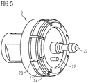
- Fig. 5 illustrates the coil counter-tool shown in Fig. 1-2 in more detail.
- the coil counter-tool 6 comprises the second winding liming surface 7.
- the coil counter-tool 6 also comprises a coil body 24.
- the coil 16 is wound between the first and second winding limiting surface 4, 7 and around the coil body 24.
- the two pins 22 ensure that the coil counter-tool 22 cannot move linearly and rotationally when the coil counter-tool 6 is connected to the tool holder 1.
- Ejectors 20 are provided on the coil-counter tool 6.
- the ejectors 20 are relatively movable to the second winding limiting surface 7 and can be moved such that they protrude from the second winding limiting surface 7.
- the coil 16 can be pushed away from the second winding limiting surface 7 and by this removed from the coil counter-tool 6 (the coil counter-tool 6 being in disconnected position with the tool holder 1).
- Fig. 6 and Fig. 7 illustrate the exchangeable tool part 12 of the embodiment as shown in Fig. 1-4 .
- Fig. 6 shows the side of the exchangeable tool part 12 on which the first winding limiting surface 4 is provided.
- Fig. 7 shows the opposite side of the side on which the first winding limiting surface 4 is provided.
- the hot air provided by the hot air source 10 is guided into the circumferential ring groove 21 on the back side of the exchangeable tool part 12.
- the circumferential ring groove 21 is fluidly connected with the hot air outlet ports 11 on the front side of the exchangeable tool part 12.
- the circumferential ring groove 21 is configured to provide all the hot air outlet ports 11 with hot air.
- Fig. 8 illustrates exemplary embodiments for configurations of hot air outlet ports 11 provided on the first winding limiting surface 4.
- Some configurations comprise a plurality of hot air outlet ports 11 with circular shape (example a) and h)), with rectangular shape (example d)) or with triangle shape (example g)).
- Other configurations comprise a hot air outlet port 11 in form of one circumferential ring groove (example b)), multiple circumferential ring grooves (example f)) or a combination of at least one circumferential ring groove with a plurality of hot air outlet ports with circular shape (example e)).
- Another configuration comprises hot air outlet ports 11 in form of grooves (example c)) uniformly distributed within circular sections of the first winding limiting surface (4).
- the present disclosure is based at least in part on the realization that there is a need for an improved manufacturing process for RFID coils of copper wire with a bonding coat.
- the bonding coat may be of Polyvinyl butyral, Polyester or Polyamide.
- a good polymerization ensures that the layers of the coil stick together and prevents the disassembly of the coil layers after production.
- the coil can be is heated already and constantly during the winding process.
- the heating may be directed to all coil layers and between the individual coil windings and not primarily on the external layers of the coil as at the known coil winding devices.
- the disclosed device and method may reduce the total heating time and may decrease the machine cycle time.
- the injected hot air preferably has a temperature of 100°C to 300°C, particularly of 140°C to 230°C. Consequently, the hot air source 10 has to produce hot air with a higher temperature which may be 200°C to 500°C, particularly at least 300°C. Summarizing, the hot air produced by the hot air source 10 has such a temperature that the temperature at the at least one outlet port is high enough, to melt the wire 18.
- the injection of hot air occurs at a radial circumferential surface of the winding gap 8.
- the injection of hot air may occur uniformly at the radial circumference surface 4 of the winding gap 8 through a plurality of hot air outlet ports 11 or through at least one circumferential ring groove. Other configurations of hot air outlet ports 11 may be used as well.
- the above described method may be performed with a coil winding device according to the present disclosure.
- the coil winding may be performed with an embodiment where the wire guiding 19 is configured to rotate around the winding gap 8, which is fixed.
- the coil winding may be performed by a rotating coil body which is provided in the winding gap 8 configured to wind the coil 16 by a rotational movement.
- the wire guiding 19 in this embodiment does not rotate.
- the coil counter-tool 6 of the coil winding device 15 may comprise an ejector 20 configured to eject the coil 16 from the coil counter-tool 6.
- the ejector 20 as well as the connection of tool-holder 1 and coil counter-tool 6 are configured to allow the automatic removal of the coil counter-tool from the tool-holder and the coil from the coil counter-tool and the realization of short processing times.
- a preferred embodiment of the tool-holder 1 of the coil winding device 15 comprises a plurality of hot air outlet ports 11 which are uniformly distributed within the first winding limiting surface 4 such that the windings 17 are heated across at least a part of the winding height h during the winding process.
- the outlet ports 11 may have different shapes for example have a circular shape, a rectangular shape or a triangle shape, all of which ensure that the windings of the coil are properly heated.
- the at least one hot air outlet port 11 includes at least one circumferential ring groove on the first winding limiting surface 4 such that the windings 17 are heated across at least a part of the winding height h during the winding process.
- the at least one circumferential ring groove may be combined with a plurality of hot air outlet ports as described above.
- Another example is a configuration which has multiple grooves uniformly distributed within circular sections of the first winding limiting surface 4.
- the first winding limiting surface 4 and the at least one hot air outlet port 11 preferably are provided on an exchangeable tool part 12.
- the exchangeable tool part 12 allows that different configurations of the first winding limiting surface 4 and/or the at least one hot air outlet port 11 can be realized by changing only the exchangeable tool part 12. The remaining part of the tool holder does not to be changed.
Landscapes
- Engineering & Computer Science (AREA)
- Power Engineering (AREA)
- Mechanical Engineering (AREA)
- Manufacturing & Machinery (AREA)
- Manufacture Of Motors, Generators (AREA)
Priority Applications (1)
| Application Number | Priority Date | Filing Date | Title |
|---|---|---|---|
| EP20165122.1A EP3885104B1 (de) | 2020-03-24 | 2020-03-24 | Spulenpolymerisierung während des wickelprozesses durch heissluft |
Applications Claiming Priority (1)
| Application Number | Priority Date | Filing Date | Title |
|---|---|---|---|
| EP20165122.1A EP3885104B1 (de) | 2020-03-24 | 2020-03-24 | Spulenpolymerisierung während des wickelprozesses durch heissluft |
Publications (2)
| Publication Number | Publication Date |
|---|---|
| EP3885104A1 true EP3885104A1 (de) | 2021-09-29 |
| EP3885104B1 EP3885104B1 (de) | 2024-06-12 |
Family
ID=69960344
Family Applications (1)
| Application Number | Title | Priority Date | Filing Date |
|---|---|---|---|
| EP20165122.1A Active EP3885104B1 (de) | 2020-03-24 | 2020-03-24 | Spulenpolymerisierung während des wickelprozesses durch heissluft |
Country Status (1)
| Country | Link |
|---|---|
| EP (1) | EP3885104B1 (de) |
Citations (2)
| Publication number | Priority date | Publication date | Assignee | Title |
|---|---|---|---|---|
| WO2009054079A1 (ja) * | 2007-10-26 | 2009-04-30 | Nittoku Engineering Co., Ltd. | コイル巻線装置及びコイル巻線方法 |
| EP2680283A2 (de) * | 2012-06-26 | 2014-01-01 | Nittoku Engineering Co., Ltd. | Vorrichtung und Verfahren zur Herstellung einer nicht kreisförmigen Spule |
-
2020
- 2020-03-24 EP EP20165122.1A patent/EP3885104B1/de active Active
Patent Citations (2)
| Publication number | Priority date | Publication date | Assignee | Title |
|---|---|---|---|---|
| WO2009054079A1 (ja) * | 2007-10-26 | 2009-04-30 | Nittoku Engineering Co., Ltd. | コイル巻線装置及びコイル巻線方法 |
| EP2680283A2 (de) * | 2012-06-26 | 2014-01-01 | Nittoku Engineering Co., Ltd. | Vorrichtung und Verfahren zur Herstellung einer nicht kreisförmigen Spule |
Also Published As
| Publication number | Publication date |
|---|---|
| EP3885104B1 (de) | 2024-06-12 |
Similar Documents
| Publication | Publication Date | Title |
|---|---|---|
| JP6891092B2 (ja) | 押出機を備える装置 | |
| JP5641635B2 (ja) | 巻線機及びそれを用いる連続コイルの製造方法 | |
| JP5559278B2 (ja) | 多色成形品の製造方法および射出成形システム | |
| US5778512A (en) | Manufacturing method for a rotor of an electric rotary machine | |
| KR101718967B1 (ko) | 복수의 유도가열 헤드를 구비한 3d 프린터 | |
| TW201532794A (zh) | 具天然球狀控制功能的3d列印機 | |
| CN203674538U (zh) | 一种自动线缆切断剥皮工装 | |
| CN109605733B (zh) | 一种磁性材料3d打印设备 | |
| CN101562377A (zh) | 空心线圈的绕线方法和绕线装置 | |
| EP3885104A1 (de) | Spulenpolymerisierung während des wickelprozesses durch heissluft | |
| JP2002500106A (ja) | ばね巻機 | |
| WO2009072750A1 (en) | Resin tube with multiple inner conduits and machine for manufacturing the tube | |
| JP2018534067A (ja) | ブラシ用の毛領域を製造するための装置、このような装置のラインおよびこのような装置を製造するための方法 | |
| KR101830218B1 (ko) | 모터 코어 제조용 가열 장치 | |
| US5916468A (en) | Electrically weldable pipe joint and production method thereof | |
| CN206083887U (zh) | 一种三爪六触点整体叶轮快速定位工装夹具 | |
| US20180068786A1 (en) | Apparatus and method for manufacturing electronic component | |
| CN203765995U (zh) | 一种纳米叠层复合挤出设备 | |
| CN113246458B (zh) | 热缩管生产装置 | |
| WO2021028017A1 (en) | Hollow permanent magnet cylinder with at least one groove or slit to reduce eddy currents | |
| CN215095633U (zh) | 一种热缩管生产装置 | |
| CN113103565A (zh) | 一种热缩管生产装置 | |
| JP6340282B2 (ja) | バリ除去装置 | |
| US20250302187A1 (en) | Device for compacting bristle bundles, bristle product production machine, and method for compacting bristle bundles | |
| CN210272067U (zh) | 用于线圈绕线机的治具 |
Legal Events
| Date | Code | Title | Description |
|---|---|---|---|
| PUAI | Public reference made under article 153(3) epc to a published international application that has entered the european phase |
Free format text: ORIGINAL CODE: 0009012 |
|
| STAA | Information on the status of an ep patent application or granted ep patent |
Free format text: STATUS: THE APPLICATION HAS BEEN PUBLISHED |
|
| AK | Designated contracting states |
Kind code of ref document: A1 Designated state(s): AL AT BE BG CH CY CZ DE DK EE ES FI FR GB GR HR HU IE IS IT LI LT LU LV MC MK MT NL NO PL PT RO RS SE SI SK SM TR |
|
| STAA | Information on the status of an ep patent application or granted ep patent |
Free format text: STATUS: REQUEST FOR EXAMINATION WAS MADE |
|
| 17P | Request for examination filed |
Effective date: 20220321 |
|
| RBV | Designated contracting states (corrected) |
Designated state(s): AL AT BE BG CH CY CZ DE DK EE ES FI FR GB GR HR HU IE IS IT LI LT LU LV MC MK MT NL NO PL PT RO RS SE SI SK SM TR |
|
| STAA | Information on the status of an ep patent application or granted ep patent |
Free format text: STATUS: EXAMINATION IS IN PROGRESS |
|
| 17Q | First examination report despatched |
Effective date: 20230420 |
|
| P01 | Opt-out of the competence of the unified patent court (upc) registered |
Effective date: 20230627 |
|
| GRAP | Despatch of communication of intention to grant a patent |
Free format text: ORIGINAL CODE: EPIDOSNIGR1 |
|
| STAA | Information on the status of an ep patent application or granted ep patent |
Free format text: STATUS: GRANT OF PATENT IS INTENDED |
|
| RIC1 | Information provided on ipc code assigned before grant |
Ipc: B29C 53/82 20060101ALN20240214BHEP Ipc: B29C 53/62 20060101ALN20240214BHEP Ipc: B29C 53/00 20060101ALN20240214BHEP Ipc: H01F 41/06 20160101ALI20240214BHEP Ipc: B29C 53/84 20060101AFI20240214BHEP |
|
| INTG | Intention to grant announced |
Effective date: 20240229 |
|
| GRAS | Grant fee paid |
Free format text: ORIGINAL CODE: EPIDOSNIGR3 |
|
| GRAA | (expected) grant |
Free format text: ORIGINAL CODE: 0009210 |
|
| STAA | Information on the status of an ep patent application or granted ep patent |
Free format text: STATUS: THE PATENT HAS BEEN GRANTED |
|
| AK | Designated contracting states |
Kind code of ref document: B1 Designated state(s): AL AT BE BG CH CY CZ DE DK EE ES FI FR GB GR HR HU IE IS IT LI LT LU LV MC MK MT NL NO PL PT RO RS SE SI SK SM TR |
|
| REG | Reference to a national code |
Ref country code: GB Ref legal event code: FG4D |
|
| REG | Reference to a national code |
Ref country code: CH Ref legal event code: EP |
|
| REG | Reference to a national code |
Ref country code: IE Ref legal event code: FG4D |
|
| REG | Reference to a national code |
Ref country code: DE Ref legal event code: R096 Ref document number: 602020032177 Country of ref document: DE |
|
| PG25 | Lapsed in a contracting state [announced via postgrant information from national office to epo] |
Ref country code: BG Free format text: LAPSE BECAUSE OF FAILURE TO SUBMIT A TRANSLATION OF THE DESCRIPTION OR TO PAY THE FEE WITHIN THE PRESCRIBED TIME-LIMIT Effective date: 20240612 |
|
| PG25 | Lapsed in a contracting state [announced via postgrant information from national office to epo] |
Ref country code: FI Free format text: LAPSE BECAUSE OF FAILURE TO SUBMIT A TRANSLATION OF THE DESCRIPTION OR TO PAY THE FEE WITHIN THE PRESCRIBED TIME-LIMIT Effective date: 20240612 Ref country code: HR Free format text: LAPSE BECAUSE OF FAILURE TO SUBMIT A TRANSLATION OF THE DESCRIPTION OR TO PAY THE FEE WITHIN THE PRESCRIBED TIME-LIMIT Effective date: 20240612 |
|
| REG | Reference to a national code |
Ref country code: LT Ref legal event code: MG9D |
|
| PG25 | Lapsed in a contracting state [announced via postgrant information from national office to epo] |
Ref country code: GR Free format text: LAPSE BECAUSE OF FAILURE TO SUBMIT A TRANSLATION OF THE DESCRIPTION OR TO PAY THE FEE WITHIN THE PRESCRIBED TIME-LIMIT Effective date: 20240913 |
|
| REG | Reference to a national code |
Ref country code: NL Ref legal event code: MP Effective date: 20240612 |
|
| PG25 | Lapsed in a contracting state [announced via postgrant information from national office to epo] |
Ref country code: ES Free format text: LAPSE BECAUSE OF FAILURE TO SUBMIT A TRANSLATION OF THE DESCRIPTION OR TO PAY THE FEE WITHIN THE PRESCRIBED TIME-LIMIT Effective date: 20240612 |
|
| PG25 | Lapsed in a contracting state [announced via postgrant information from national office to epo] |
Ref country code: LV Free format text: LAPSE BECAUSE OF FAILURE TO SUBMIT A TRANSLATION OF THE DESCRIPTION OR TO PAY THE FEE WITHIN THE PRESCRIBED TIME-LIMIT Effective date: 20240612 |
|
| PG25 | Lapsed in a contracting state [announced via postgrant information from national office to epo] |
Ref country code: NO Free format text: LAPSE BECAUSE OF FAILURE TO SUBMIT A TRANSLATION OF THE DESCRIPTION OR TO PAY THE FEE WITHIN THE PRESCRIBED TIME-LIMIT Effective date: 20240912 Ref country code: LV Free format text: LAPSE BECAUSE OF FAILURE TO SUBMIT A TRANSLATION OF THE DESCRIPTION OR TO PAY THE FEE WITHIN THE PRESCRIBED TIME-LIMIT Effective date: 20240612 Ref country code: HR Free format text: LAPSE BECAUSE OF FAILURE TO SUBMIT A TRANSLATION OF THE DESCRIPTION OR TO PAY THE FEE WITHIN THE PRESCRIBED TIME-LIMIT Effective date: 20240612 Ref country code: GR Free format text: LAPSE BECAUSE OF FAILURE TO SUBMIT A TRANSLATION OF THE DESCRIPTION OR TO PAY THE FEE WITHIN THE PRESCRIBED TIME-LIMIT Effective date: 20240913 Ref country code: FI Free format text: LAPSE BECAUSE OF FAILURE TO SUBMIT A TRANSLATION OF THE DESCRIPTION OR TO PAY THE FEE WITHIN THE PRESCRIBED TIME-LIMIT Effective date: 20240612 Ref country code: ES Free format text: LAPSE BECAUSE OF FAILURE TO SUBMIT A TRANSLATION OF THE DESCRIPTION OR TO PAY THE FEE WITHIN THE PRESCRIBED TIME-LIMIT Effective date: 20240612 Ref country code: BG Free format text: LAPSE BECAUSE OF FAILURE TO SUBMIT A TRANSLATION OF THE DESCRIPTION OR TO PAY THE FEE WITHIN THE PRESCRIBED TIME-LIMIT Effective date: 20240612 Ref country code: RS Free format text: LAPSE BECAUSE OF FAILURE TO SUBMIT A TRANSLATION OF THE DESCRIPTION OR TO PAY THE FEE WITHIN THE PRESCRIBED TIME-LIMIT Effective date: 20240912 |
|
| PG25 | Lapsed in a contracting state [announced via postgrant information from national office to epo] |
Ref country code: NL Free format text: LAPSE BECAUSE OF FAILURE TO SUBMIT A TRANSLATION OF THE DESCRIPTION OR TO PAY THE FEE WITHIN THE PRESCRIBED TIME-LIMIT Effective date: 20240612 |
|
| REG | Reference to a national code |
Ref country code: AT Ref legal event code: MK05 Ref document number: 1693867 Country of ref document: AT Kind code of ref document: T Effective date: 20240612 |
|
| PG25 | Lapsed in a contracting state [announced via postgrant information from national office to epo] |
Ref country code: NL Free format text: LAPSE BECAUSE OF FAILURE TO SUBMIT A TRANSLATION OF THE DESCRIPTION OR TO PAY THE FEE WITHIN THE PRESCRIBED TIME-LIMIT Effective date: 20240612 |
|
| PG25 | Lapsed in a contracting state [announced via postgrant information from national office to epo] |
Ref country code: PT Free format text: LAPSE BECAUSE OF FAILURE TO SUBMIT A TRANSLATION OF THE DESCRIPTION OR TO PAY THE FEE WITHIN THE PRESCRIBED TIME-LIMIT Effective date: 20241014 |
|
| PG25 | Lapsed in a contracting state [announced via postgrant information from national office to epo] |
Ref country code: PT Free format text: LAPSE BECAUSE OF FAILURE TO SUBMIT A TRANSLATION OF THE DESCRIPTION OR TO PAY THE FEE WITHIN THE PRESCRIBED TIME-LIMIT Effective date: 20241014 |
|
| PG25 | Lapsed in a contracting state [announced via postgrant information from national office to epo] |
Ref country code: PL Free format text: LAPSE BECAUSE OF FAILURE TO SUBMIT A TRANSLATION OF THE DESCRIPTION OR TO PAY THE FEE WITHIN THE PRESCRIBED TIME-LIMIT Effective date: 20240612 |
|
| PG25 | Lapsed in a contracting state [announced via postgrant information from national office to epo] |
Ref country code: EE Free format text: LAPSE BECAUSE OF FAILURE TO SUBMIT A TRANSLATION OF THE DESCRIPTION OR TO PAY THE FEE WITHIN THE PRESCRIBED TIME-LIMIT Effective date: 20240612 |
|
| PG25 | Lapsed in a contracting state [announced via postgrant information from national office to epo] |
Ref country code: IS Free format text: LAPSE BECAUSE OF FAILURE TO SUBMIT A TRANSLATION OF THE DESCRIPTION OR TO PAY THE FEE WITHIN THE PRESCRIBED TIME-LIMIT Effective date: 20241012 Ref country code: AT Free format text: LAPSE BECAUSE OF FAILURE TO SUBMIT A TRANSLATION OF THE DESCRIPTION OR TO PAY THE FEE WITHIN THE PRESCRIBED TIME-LIMIT Effective date: 20240612 |
|
| PG25 | Lapsed in a contracting state [announced via postgrant information from national office to epo] |
Ref country code: CZ Free format text: LAPSE BECAUSE OF FAILURE TO SUBMIT A TRANSLATION OF THE DESCRIPTION OR TO PAY THE FEE WITHIN THE PRESCRIBED TIME-LIMIT Effective date: 20240612 |
|
| PG25 | Lapsed in a contracting state [announced via postgrant information from national office to epo] |
Ref country code: RO Free format text: LAPSE BECAUSE OF FAILURE TO SUBMIT A TRANSLATION OF THE DESCRIPTION OR TO PAY THE FEE WITHIN THE PRESCRIBED TIME-LIMIT Effective date: 20240612 Ref country code: SK Free format text: LAPSE BECAUSE OF FAILURE TO SUBMIT A TRANSLATION OF THE DESCRIPTION OR TO PAY THE FEE WITHIN THE PRESCRIBED TIME-LIMIT Effective date: 20240612 |
|
| PG25 | Lapsed in a contracting state [announced via postgrant information from national office to epo] |
Ref country code: SM Free format text: LAPSE BECAUSE OF FAILURE TO SUBMIT A TRANSLATION OF THE DESCRIPTION OR TO PAY THE FEE WITHIN THE PRESCRIBED TIME-LIMIT Effective date: 20240612 |
|
| PG25 | Lapsed in a contracting state [announced via postgrant information from national office to epo] |
Ref country code: SM Free format text: LAPSE BECAUSE OF FAILURE TO SUBMIT A TRANSLATION OF THE DESCRIPTION OR TO PAY THE FEE WITHIN THE PRESCRIBED TIME-LIMIT Effective date: 20240612 Ref country code: SK Free format text: LAPSE BECAUSE OF FAILURE TO SUBMIT A TRANSLATION OF THE DESCRIPTION OR TO PAY THE FEE WITHIN THE PRESCRIBED TIME-LIMIT Effective date: 20240612 Ref country code: RO Free format text: LAPSE BECAUSE OF FAILURE TO SUBMIT A TRANSLATION OF THE DESCRIPTION OR TO PAY THE FEE WITHIN THE PRESCRIBED TIME-LIMIT Effective date: 20240612 Ref country code: PL Free format text: LAPSE BECAUSE OF FAILURE TO SUBMIT A TRANSLATION OF THE DESCRIPTION OR TO PAY THE FEE WITHIN THE PRESCRIBED TIME-LIMIT Effective date: 20240612 Ref country code: IS Free format text: LAPSE BECAUSE OF FAILURE TO SUBMIT A TRANSLATION OF THE DESCRIPTION OR TO PAY THE FEE WITHIN THE PRESCRIBED TIME-LIMIT Effective date: 20241012 Ref country code: EE Free format text: LAPSE BECAUSE OF FAILURE TO SUBMIT A TRANSLATION OF THE DESCRIPTION OR TO PAY THE FEE WITHIN THE PRESCRIBED TIME-LIMIT Effective date: 20240612 Ref country code: CZ Free format text: LAPSE BECAUSE OF FAILURE TO SUBMIT A TRANSLATION OF THE DESCRIPTION OR TO PAY THE FEE WITHIN THE PRESCRIBED TIME-LIMIT Effective date: 20240612 Ref country code: AT Free format text: LAPSE BECAUSE OF FAILURE TO SUBMIT A TRANSLATION OF THE DESCRIPTION OR TO PAY THE FEE WITHIN THE PRESCRIBED TIME-LIMIT Effective date: 20240612 |
|
| PG25 | Lapsed in a contracting state [announced via postgrant information from national office to epo] |
Ref country code: IT Free format text: LAPSE BECAUSE OF FAILURE TO SUBMIT A TRANSLATION OF THE DESCRIPTION OR TO PAY THE FEE WITHIN THE PRESCRIBED TIME-LIMIT Effective date: 20240612 |
|
| REG | Reference to a national code |
Ref country code: DE Ref legal event code: R097 Ref document number: 602020032177 Country of ref document: DE |
|
| PG25 | Lapsed in a contracting state [announced via postgrant information from national office to epo] |
Ref country code: DK Free format text: LAPSE BECAUSE OF FAILURE TO SUBMIT A TRANSLATION OF THE DESCRIPTION OR TO PAY THE FEE WITHIN THE PRESCRIBED TIME-LIMIT Effective date: 20240612 |
|
| PLBE | No opposition filed within time limit |
Free format text: ORIGINAL CODE: 0009261 |
|
| STAA | Information on the status of an ep patent application or granted ep patent |
Free format text: STATUS: NO OPPOSITION FILED WITHIN TIME LIMIT |
|
| 26N | No opposition filed |
Effective date: 20250313 |
|
| PG25 | Lapsed in a contracting state [announced via postgrant information from national office to epo] |
Ref country code: SE Free format text: LAPSE BECAUSE OF FAILURE TO SUBMIT A TRANSLATION OF THE DESCRIPTION OR TO PAY THE FEE WITHIN THE PRESCRIBED TIME-LIMIT Effective date: 20240612 |
|
| PG25 | Lapsed in a contracting state [announced via postgrant information from national office to epo] |
Ref country code: MC Free format text: LAPSE BECAUSE OF FAILURE TO SUBMIT A TRANSLATION OF THE DESCRIPTION OR TO PAY THE FEE WITHIN THE PRESCRIBED TIME-LIMIT Effective date: 20240612 |
|
| REG | Reference to a national code |
Ref country code: CH Ref legal event code: H13 Free format text: ST27 STATUS EVENT CODE: U-0-0-H10-H13 (AS PROVIDED BY THE NATIONAL OFFICE) Effective date: 20251024 |
|
| PG25 | Lapsed in a contracting state [announced via postgrant information from national office to epo] |
Ref country code: LU Free format text: LAPSE BECAUSE OF NON-PAYMENT OF DUE FEES Effective date: 20250324 |
|
| GBPC | Gb: european patent ceased through non-payment of renewal fee |
Effective date: 20250324 |
|
| REG | Reference to a national code |
Ref country code: BE Ref legal event code: MM Effective date: 20250331 |
|
| PG25 | Lapsed in a contracting state [announced via postgrant information from national office to epo] |
Ref country code: GB Free format text: LAPSE BECAUSE OF NON-PAYMENT OF DUE FEES Effective date: 20250324 |
|
| PG25 | Lapsed in a contracting state [announced via postgrant information from national office to epo] |
Ref country code: BE Free format text: LAPSE BECAUSE OF NON-PAYMENT OF DUE FEES Effective date: 20250331 |
|
| PG25 | Lapsed in a contracting state [announced via postgrant information from national office to epo] |
Ref country code: CH Free format text: LAPSE BECAUSE OF NON-PAYMENT OF DUE FEES Effective date: 20250331 |
|
| PG25 | Lapsed in a contracting state [announced via postgrant information from national office to epo] |
Ref country code: IE Free format text: LAPSE BECAUSE OF NON-PAYMENT OF DUE FEES Effective date: 20250324 |
|
| PGFP | Annual fee paid to national office [announced via postgrant information from national office to epo] |
Ref country code: DE Payment date: 20260211 Year of fee payment: 7 |
|
| PGFP | Annual fee paid to national office [announced via postgrant information from national office to epo] |
Ref country code: FR Payment date: 20260209 Year of fee payment: 7 |