EP3884803A1 - Male snap button and female snap button - Google Patents
Male snap button and female snap button Download PDFInfo
- Publication number
- EP3884803A1 EP3884803A1 EP18940663.0A EP18940663A EP3884803A1 EP 3884803 A1 EP3884803 A1 EP 3884803A1 EP 18940663 A EP18940663 A EP 18940663A EP 3884803 A1 EP3884803 A1 EP 3884803A1
- Authority
- EP
- European Patent Office
- Prior art keywords
- fabric
- female
- male
- radial direction
- snap body
- Prior art date
- Legal status (The legal status is an assumption and is not a legal conclusion. Google has not performed a legal analysis and makes no representation as to the accuracy of the status listed.)
- Granted
Links
Images





Classifications
-
- A—HUMAN NECESSITIES
- A44—HABERDASHERY; JEWELLERY
- A44B—BUTTONS, PINS, BUCKLES, SLIDE FASTENERS, OR THE LIKE
- A44B17/00—Press-button or snap fasteners
- A44B17/0064—Details
- A44B17/007—Stud-member
-
- A—HUMAN NECESSITIES
- A44—HABERDASHERY; JEWELLERY
- A44B—BUTTONS, PINS, BUCKLES, SLIDE FASTENERS, OR THE LIKE
- A44B17/00—Press-button or snap fasteners
- A44B17/0041—Press-button fasteners consisting of two parts
-
- A—HUMAN NECESSITIES
- A44—HABERDASHERY; JEWELLERY
- A44B—BUTTONS, PINS, BUCKLES, SLIDE FASTENERS, OR THE LIKE
- A44B17/00—Press-button or snap fasteners
- A44B17/0005—Fastening of press-button fasteners
-
- A—HUMAN NECESSITIES
- A44—HABERDASHERY; JEWELLERY
- A44B—BUTTONS, PINS, BUCKLES, SLIDE FASTENERS, OR THE LIKE
- A44B17/00—Press-button or snap fasteners
- A44B17/0064—Details
- A44B17/0076—Socket member
-
- A—HUMAN NECESSITIES
- A44—HABERDASHERY; JEWELLERY
- A44B—BUTTONS, PINS, BUCKLES, SLIDE FASTENERS, OR THE LIKE
- A44B17/00—Press-button or snap fasteners
- A44B17/0064—Details
- A44B17/0088—Details made from sheet metal
Definitions
- the present invention relates to a male snap button and a female snap button, and particularly to a male snap button and a female snap button which each include a plurality of claws to be crimped after the claws penetrate fabric such as clothes and which are basically made of a metal.
- a metal snap button including a plurality of claws is disclosed in, for example, PCT International Publication No. WO2018/029765 (Patent Literature 1) and the like.
- the snap button of Patent Literature 1 is constituted by a male or female snap body (a snap body) including a male-side or female-side engagement part and a fixing member, the fixing member is provided with a plurality of claws, and the snap body is provided with a claw accommodation part which receives the plurality of claws.
- the snap body and the fixing member are attached to fabric, the claws of the fixing member penetrate the fabric, and then the claws are accommodated in the claw accommodation part while being crimped, and thus the snap body is fixed to the fabric together with the fixing member.
- this snap button is provided with the claw accommodation part on the snap body side, there is a problem that a thickness (a height) of the snap body on the fabric is increased by a thickness of the claw accommodation part.
- Patent Literature 2 discloses a female snap button in which a plurality of claws is provided on a snap body side.
- this female snap button by providing a claw accommodation part on a fixing member side, it is possible to reduce a thickness of the snap body on fabric.
- the fabric is partially hidden by the snap button being attached to the fabric such as clothes, but there is a demand to make a portion of the fabric which is hidden as small as possible so that the fabric is more noticeable or the snap button is less noticeable.
- a demand is realized by a resin snap button formed by injection molding a resin on the fabric.
- a metal snap button which is basically made of a metal.
- an objective of the present invention is to provide a male snap button and a female snap button which can make fabric more noticeable when attached to the fabric and which are basically made of a metal.
- a male snap button including a male snap body made of metal, and a fixing member configured for fixing the male snap body to a fabric
- the male snap body includes a male-side engagement part in annular shape that is capable of being removably engaged with a female-side engagement part of a female snap button, and a plurality of claws.
- the male-side engagement part defines an opening that exposes the fabric inside in a radial direction thereof. A diameter of the opening is greater than a length in the radial direction from an outside edge of the opening in the radial direction to an outside edge of the male snap body in the radial direction.
- the fixing member includes a claw accommodation part configured to receive the plurality of claws.
- the male snap button includes the male snap body made of metal and the fixing member.
- the male snap body includes the male-side engagement part and the plurality of claws
- the fixing member includes the claw accommodation part configured to receive the plurality of claws.
- the male-side engagement part defines the opening that exposes the fabric inside in the radial direction thereof, and the diameter of the opening is greater than the length in the radial direction from the outside edge of the opening in the radial direction to the outside edge of the male snap body in the radial direction.
- the length in the radial direction from the outside edge of the opening in the radial direction to the outside edge of the male snap body in the radial direction is referred to as, in other words, a width of the male snap body surrounding the opening in the radial direction (therefore, hereinafter also referred to as a "male snap body width").
- the male snap button is attached to the fabric
- the plurality of claws of the male snap body penetrates the fabric from one surface side to another surface side, and on the other surface side of the fabric, the plurality of claws is accommodated in the claw accommodation part of the fixing member while being crimped. Accordingly, the male snap body is attached to the fabric together with the fixing member.
- the male-side engagement part of the male snap body which is a portion other than the claws appears on the one surface side of the fabric, and the fixing member is applied from the other surface side of the fabric.
- the male snap button is attached to the fabric
- the fabric surface is exposed to the outside from the opening, but since the diameter of the opening is larger than the male snap body width, it is possible to relatively largely expose one surface side of the fabric on the male snap body side.
- the male snap body width is small as compared with the diameter of the opening that exposes the fabric while it is possible to make the fabric noticeable, and thus it is possible to make the male snap body inconspicuous on the fabric.
- the male-side engagement part includes an inside peripheral wall that defines the opening, and the plurality of claws extends from the inside peripheral wall.
- the inside peripheral wall of the male-side engagement part is located furthest inside in the radial direction in the male snap body and defines the opening.
- each claw extends from the inside peripheral wall. Therefore, a proximal edge of each claw is located at the same position as the inside peripheral wall in the radial direction. Accordingly, other portions of the male snap body are not present inside the inside peripheral wall and the proximal edges of the claws in the radial direction in the male snap body, and the opening of the inside peripheral wall for exposing the fabric can be set as large as possible.
- the male snap body is formed of a metal such as aluminum, an aluminum alloy, copper, a copper alloy, iron, or stainless steel, but the present invention is not limited thereto.
- the fixing member can be formed of the same metal as the male snap body, a thermoplastic resin, or the like.
- the number of the claws included in the fixing member is at least two, preferably three or more, and particularly preferably four to six, but the present invention is not limited thereto.
- a female snap button including a female snap body, and a fixing member configured for fixing the female snap body to a fabric
- the female snap body includes a female-side engagement member in annular shape that is capable of being removably engaged with a male-side engagement part of a male snap button, an annular member made of metal including a holding part that holds the female-side engagement member, and a plurality of claws made of metal.
- the female-side engagement member or the annular member defines an opening that exposes the fabric inside in a radial direction thereof. A diameter of the opening is greater than a length in the radial direction from an outside edge of the opening in the radial direction to an outside edge of the female snap body in the radial direction.
- the fixing member includes a claw accommodation part configured to receive the plurality of claws.
- the female snap button includes the female snap body and the fixing member.
- the female snap body includes the female-side engagement member, the annular member made of metal, and the plurality of claws made of metal.
- the annular member includes the holding part that holds the female-side engagement member.
- the female-side engagement member or the annular member defines the opening that exposes the fabric inside in the radial direction thereof. And, the diameter of the opening is greater than the length in the radial direction from the outside edge of the opening in the radial direction to the outside edge of the female snap body in the radial direction (hereinafter also referred to as a "female snap body width").
- the plurality of claws of the female snap body penetrates the fabric from one surface side to another surface side, and on the other surface side of the fabric, the plurality of claws is accommodated in the claw accommodation part of the fixing member while being crimped. Accordingly, the female snap body is attached to the fabric together with the fixing member. In this state of being attached to the fabric, the annular member of which the holding part holds the female-side engagement member of the female snap body which is a portion other than the claws appears on the one surface side of the fabric, and the fixing member is applied from the other surface side of the fabric.
- the fabric surface is exposed to the outside from the opening, but since the diameter of the opening is larger than the female snap body width, it is possible to relatively largely expose one surface side of the fabric on the female snap body side.
- the male snap body width is small as compared with the diameter of the opening that exposes the fabric while it is possible to make the fabric noticeable, and thus it is possible to make the female snap body inconspicuous on the fabric.
- the radially inside edge of the female-side engagement member is located inside the radially inside edge of the annular member in the radial direction. Further, in a case in which the annular member defines the opening, the radially inside edge of the annular member is located inside the radially inside edge of the female-side engagement member in the radial direction.
- the annular member includes a bottom wall, the plurality of claws extends from a radially inside edge of the bottom wall, and the radially inside edge of the bottom wall and proximal edges of the plurality of claws define the opening.
- the bottom wall of the annular member extends furthest inward in the female snap body in the radial direction, each claw extends from the radially inside edge of the bottom wall, and the radially inside edge of the bottom wall and the proximal edges of the plurality of the claws define the opening. Therefore, other portions or members of the female snap body are not present inside the bottom wall and the proximal edges of the claws in the radial direction in the female snap body, and the opening for exposing the fabric can be set as large as possible.
- the annular member and the claw member of the female snap body which are portions other than the female-side engagement member are formed of a metal such as aluminum, an aluminum alloy, copper, a copper alloy, iron, or stainless steel, but the present invention is not limited thereto.
- the female-side engagement member is formed of a thermoplastic resin, a thermosetting resin, or the same metal as the annular member and the claw member, but the present invention is not limited thereto.
- the fixing member can be formed of the same metal as the annular member and the claw member, a thermoplastic resin, or the like.
- the number of the claws included in the fixing member is at least two, preferably three or more, and particularly preferably four to six, but the present invention is not limited thereto.
- the male snap button and the female snap button which are basically made of a metal, by making the diameter of the opening that exposes the fabric larger than the male or female snap body width to relatively largely expose the fabric while hiding the fabric with the male or female snap body as little as possible, it is possible to make the fabric more noticeable.
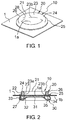
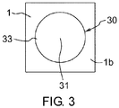
- FIGs. 1 and 2 are a perspective view and a cross-sectional view showing a male snap button 10 according to an embodiment of the present invention when attached to a fabric 1.
- the male snap button 10 includes two components, i.e., a male snap body 20 and a fixing member 30.
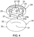
- FIG. 3 is a plan view of the male snap button 10 attached to the fabric 1 from a fixing member 30 side.
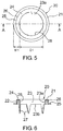
- FIG. 4 is a perspective view showing the male snap body 20 and the fixing member 30 before being attached to the fabric 1.
- FIG. 5 is a plan view of the male snap body 20.
- FIG. 6 is a cross-sectional view of the male snap body 20 along line A-A in FIG. 5 .
- FIG. 7 is a cross-sectional view of the fixing member 30.
- the male snap body 20 is a single member formed by subjecting a metal plate material to drawing processing and includes an annular male-side engagement part 21 and claws 27 which extend axially downward from the male-side engagement part 21 and of which the number is five as an example.
- the male-side engagement part 21 is a portion that removably engages with a female-side engagement member 60 which is a male-side engagement part of a female snap button 40 which will be described later.
- the male-side engagement part 21 appears on an upper surface (one surface) 1a of the fabric 1 in a state in which the male snap button 10 is attached to the fabric 1.
- the male-side engagement part 21 of the male snap body 20 includes an outside peripheral wall 22, an inside peripheral wall 23, a connecting part 24 that connects upper edges of the outside and inside peripheral walls 22 and 23, and an annular flange 25 that extends outward from a lower edge of the outside peripheral wall 22 in a radial direction.
- the annular flange 25 extends furthest outward in the male snap body 20 in the radial direction.
- a gap is present between the outside peripheral wall 22 and the inside peripheral wall 23.
- the outside peripheral wall 22 has an engagement head 26 in an upper edge portion of which an outer diameter becomes maximum.
- the inside peripheral wall 23 is located furthest inside in the radial direction in the male-side engagement part 21, and an inner peripheral surface 23a of the inside peripheral wall 23 defines a circular opening 28 that opens vertically.
- a diameter D1 of the opening 28 is greater than a length (a male snap body width) W1 in the radial direction from an outside edge of the opening 28 in the radial direction to an outside edge of the male snap body 20 in the radial direction, that is, to an outside edge of the annular flange 25 in the radial direction.
- D1 is about three times W1.
- Each claw 27 extends continuously downward from a lower edge 23b of the inside peripheral wall 23 of the male-side engagement part 21.
- the claws 27 are provided in the lower edge 23b of the inside peripheral wall 23 at equal intervals in a circumferential direction.
- a width of each claw 27 in the circumferential direction is reduced from a proximal edge on an upper side toward a lower side, and a lower edge (a tip edge) thereof becomes sharp.
- each claw 27 extends substantially parallel to an axis of the male snap body 20.
- a position of the proximal edge (an upper edge) of each claw 27 in the radial direction is substantially the same as a position of the inside peripheral wall 23 of the male-side engagement part 21 in the radial direction. Therefore, in the male snap body 20, the inside peripheral wall 23 and the proximal edges of the claws 27 are furthest inside in the radial direction, and other portions of the male snap body 20 are not inside the inside peripheral wall 23 and the proximal edges of the claws 27 in the radial direction.
- each claw 27 penetrates the fabric 1 from the upper surface 1a side to the lower surface 1b side and then is received in a claw accommodation part 33, which will be described later, of the fixing member 30 while being bent.
- the central part 31 is opened (see FIG. 18 ), or, although not shown, the central part 31 is cut out in the shape of characters, symbols, figures, and the like, and thus it is possible to give a design of a through hole shape to the central part 31.
- the claw accommodation part 33 includes a substantially flat distal edge portion 34.
- the distal edge portion 34 is located slightly upward from the central part 31 in the vertical direction (an axial direction).
- a distal edge 34a of the distal edge portion 34 is located in the vicinity of a boundary between the annular inclined part 32 and the claw accommodation part 33 in the radial direction.
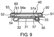
- FIGs. 8 and 9 are a perspective view and a cross-sectional view showing a female snap button 40 according to an embodiment of the present invention when attached to fabric 2.
- the female snap button 40 includes two members, i.e., a female snap body 50 and a fixing member 30.
- the fixing member 30 is a common member to the fixing member 30 of the male snap button 10 described above.
- FIG. 10 is a perspective view showing the female snap body 50 and the fixing member 30 before being attached to the fabric 2.
- FIG. 11 is a plan view of the female snap body 50.
- FIG. 12 is a cross-sectional view of the female snap body 50 along line B-B in FIG. 11 .
- the female-side engagement member 60 has an engagement edge 61 at which an inner diameter thereof becomes minimum slightly above a middle thereof in the vertical direction.
- the annular member 51A and the claws 57 are a single member formed by drawing a metal plate material.
- the annular member 51A appears on an upper surface (one surface) 2a of the fabric 2 together with the female-side engagement member 60 in a state in which the female snap button 40 is attached to the fabric 2.
- a diameter D2 of the opening 58 is greater than a length (a female snap body width) W2 in the radial direction from an outside edge of the opening 58 in the radial direction to the peripheral side wall 52 which is an outside edge of the female snap body 50 in the radial direction.
- D2 is about three times W2.
Landscapes
- Slide Fasteners, Snap Fasteners, And Hook Fasteners (AREA)
- Buckles (AREA)
Abstract
Description
- The present invention relates to a male snap button and a female snap button, and particularly to a male snap button and a female snap button which each include a plurality of claws to be crimped after the claws penetrate fabric such as clothes and which are basically made of a metal.
- A metal snap button including a plurality of claws is disclosed in, for example,
PCT International Publication No. WO2018/029765 (Patent Literature 1) and the like. The snap button ofPatent Literature 1 is constituted by a male or female snap body (a snap body) including a male-side or female-side engagement part and a fixing member, the fixing member is provided with a plurality of claws, and the snap body is provided with a claw accommodation part which receives the plurality of claws. In a case in which the snap body and the fixing member are attached to fabric, the claws of the fixing member penetrate the fabric, and then the claws are accommodated in the claw accommodation part while being crimped, and thus the snap body is fixed to the fabric together with the fixing member. However, since this snap button is provided with the claw accommodation part on the snap body side, there is a problem that a thickness (a height) of the snap body on the fabric is increased by a thickness of the claw accommodation part. -
Japanese Examined Patent Application Publication No. H6-61289 - The fabric is partially hidden by the snap button being attached to the fabric such as clothes, but there is a demand to make a portion of the fabric which is hidden as small as possible so that the fabric is more noticeable or the snap button is less noticeable. Such a demand is realized by a resin snap button formed by injection molding a resin on the fabric. However, practically, the demand is not realized in a metal snap button which is basically made of a metal.
-
- [Patent Literature 1]
PCT International Publication No. WO2018/029765 - [Patent Literature 2]
Japanese Examined Patent Application Publication No. H6-61289 - Therefore, an objective of the present invention is to provide a male snap button and a female snap button which can make fabric more noticeable when attached to the fabric and which are basically made of a metal.
- To solve the above problems, according to one aspect of the present invention, there is provided a male snap button including a male snap body made of metal, and a fixing member configured for fixing the male snap body to a fabric, in which the male snap body includes a male-side engagement part in annular shape that is capable of being removably engaged with a female-side engagement part of a female snap button, and a plurality of claws. The male-side engagement part defines an opening that exposes the fabric inside in a radial direction thereof. A diameter of the opening is greater than a length in the radial direction from an outside edge of the opening in the radial direction to an outside edge of the male snap body in the radial direction. And, the fixing member includes a claw accommodation part configured to receive the plurality of claws.
- In the present invention, the male snap button includes the male snap body made of metal and the fixing member. The male snap body includes the male-side engagement part and the plurality of claws, and the fixing member includes the claw accommodation part configured to receive the plurality of claws. The male-side engagement part defines the opening that exposes the fabric inside in the radial direction thereof, and the diameter of the opening is greater than the length in the radial direction from the outside edge of the opening in the radial direction to the outside edge of the male snap body in the radial direction. The length in the radial direction from the outside edge of the opening in the radial direction to the outside edge of the male snap body in the radial direction is referred to as, in other words, a width of the male snap body surrounding the opening in the radial direction (therefore, hereinafter also referred to as a "male snap body width"). In a case in which the male snap button is attached to the fabric, the plurality of claws of the male snap body penetrates the fabric from one surface side to another surface side, and on the other surface side of the fabric, the plurality of claws is accommodated in the claw accommodation part of the fixing member while being crimped. Accordingly, the male snap body is attached to the fabric together with the fixing member. In this state of being attached to the fabric, the male-side engagement part of the male snap body which is a portion other than the claws appears on the one surface side of the fabric, and the fixing member is applied from the other surface side of the fabric. In a state in which the male snap button is attached to the fabric, the fabric surface is exposed to the outside from the opening, but since the diameter of the opening is larger than the male snap body width, it is possible to relatively largely expose one surface side of the fabric on the male snap body side. In this way, the male snap body width is small as compared with the diameter of the opening that exposes the fabric while it is possible to make the fabric noticeable, and thus it is possible to make the male snap body inconspicuous on the fabric.
- In one embodiment of the present invention, the male-side engagement part includes an inside peripheral wall that defines the opening, and the plurality of claws extends from the inside peripheral wall. In the present embodiment, the inside peripheral wall of the male-side engagement part is located furthest inside in the radial direction in the male snap body and defines the opening. In addition, each claw extends from the inside peripheral wall. Therefore, a proximal edge of each claw is located at the same position as the inside peripheral wall in the radial direction. Accordingly, other portions of the male snap body are not present inside the inside peripheral wall and the proximal edges of the claws in the radial direction in the male snap body, and the opening of the inside peripheral wall for exposing the fabric can be set as large as possible.
- In the present invention, the male snap body is formed of a metal such as aluminum, an aluminum alloy, copper, a copper alloy, iron, or stainless steel, but the present invention is not limited thereto. The fixing member can be formed of the same metal as the male snap body, a thermoplastic resin, or the like. The number of the claws included in the fixing member is at least two, preferably three or more, and particularly preferably four to six, but the present invention is not limited thereto.
- According to another aspect of the present invention, there is provided a female snap button including a female snap body, and a fixing member configured for fixing the female snap body to a fabric, in which the female snap body includes a female-side engagement member in annular shape that is capable of being removably engaged with a male-side engagement part of a male snap button, an annular member made of metal including a holding part that holds the female-side engagement member, and a plurality of claws made of metal. The female-side engagement member or the annular member defines an opening that exposes the fabric inside in a radial direction thereof. A diameter of the opening is greater than a length in the radial direction from an outside edge of the opening in the radial direction to an outside edge of the female snap body in the radial direction. And, the fixing member includes a claw accommodation part configured to receive the plurality of claws.
- In the present invention, the female snap button includes the female snap body and the fixing member. The female snap body includes the female-side engagement member, the annular member made of metal, and the plurality of claws made of metal. And, the annular member includes the holding part that holds the female-side engagement member. The female-side engagement member or the annular member defines the opening that exposes the fabric inside in the radial direction thereof. And, the diameter of the opening is greater than the length in the radial direction from the outside edge of the opening in the radial direction to the outside edge of the female snap body in the radial direction (hereinafter also referred to as a "female snap body width"). In a case in which the female snap button is attached to the fabric, the plurality of claws of the female snap body penetrates the fabric from one surface side to another surface side, and on the other surface side of the fabric, the plurality of claws is accommodated in the claw accommodation part of the fixing member while being crimped. Accordingly, the female snap body is attached to the fabric together with the fixing member. In this state of being attached to the fabric, the annular member of which the holding part holds the female-side engagement member of the female snap body which is a portion other than the claws appears on the one surface side of the fabric, and the fixing member is applied from the other surface side of the fabric. In a state in which the female snap button is attached to the fabric, the fabric surface is exposed to the outside from the opening, but since the diameter of the opening is larger than the female snap body width, it is possible to relatively largely expose one surface side of the fabric on the female snap body side. In this way, the male snap body width is small as compared with the diameter of the opening that exposes the fabric while it is possible to make the fabric noticeable, and thus it is possible to make the female snap body inconspicuous on the fabric.
- In the present invention, in a case in which the female-side engagement member defines the opening, the radially inside edge of the female-side engagement member is located inside the radially inside edge of the annular member in the radial direction. Further, in a case in which the annular member defines the opening, the radially inside edge of the annular member is located inside the radially inside edge of the female-side engagement member in the radial direction.
- In one embodiment of the present invention, the annular member includes a bottom wall, the plurality of claws extends from a radially inside edge of the bottom wall, and the radially inside edge of the bottom wall and proximal edges of the plurality of claws define the opening. In the present embodiment, the bottom wall of the annular member extends furthest inward in the female snap body in the radial direction, each claw extends from the radially inside edge of the bottom wall, and the radially inside edge of the bottom wall and the proximal edges of the plurality of the claws define the opening. Therefore, other portions or members of the female snap body are not present inside the bottom wall and the proximal edges of the claws in the radial direction in the female snap body, and the opening for exposing the fabric can be set as large as possible.
- In the present invention, the annular member and the claw member of the female snap body which are portions other than the female-side engagement member are formed of a metal such as aluminum, an aluminum alloy, copper, a copper alloy, iron, or stainless steel, but the present invention is not limited thereto. The female-side engagement member is formed of a thermoplastic resin, a thermosetting resin, or the same metal as the annular member and the claw member, but the present invention is not limited thereto. The fixing member can be formed of the same metal as the annular member and the claw member, a thermoplastic resin, or the like. The number of the claws included in the fixing member is at least two, preferably three or more, and particularly preferably four to six, but the present invention is not limited thereto.
- In the present invention, in the male snap button and the female snap button which are basically made of a metal, by making the diameter of the opening that exposes the fabric larger than the male or female snap body width to relatively largely expose the fabric while hiding the fabric with the male or female snap body as little as possible, it is possible to make the fabric more noticeable.
-
-
FIG. 1 is a perspective view showing a male snap button according to an embodiment of the present invention when attached to a fabric. -
FIG. 2 is a cross-sectional view of the male snap button inFIG. 1 . -
FIG. 3 is a plan view of the male snap button attached to the fabric from a fixing member side. -
FIG. 4 is a perspective view showing a male snap body and a fixing member before being attached to the fabric. -
FIG. 5 is a plan view of the male snap body. -
FIG. 6 is a cross-sectional view of the male snap body along line A-A inFIG. 5 . -
FIG. 7 is a cross-sectional view of the fixing member. -
FIG. 8 is a perspective view showing a female snap button according to an embodiment of the present invention when attached to the fabric. -
FIG. 9 is a cross-sectional view of the female snap button inFIG. 8 . -
FIG. 10 is a perspective view showing a female snap body and a fixing member before being attached to the fabric. -
FIG. 11 is a plan view of the female snap body. -
FIG. 12 is a cross-sectional view of thefemale snap body 50 along line B-B inFIG. 11 . -
FIG. 13 is a cross-sectional view showing the male snap button and the female snap button when engaged with each other. -
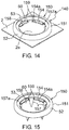
FIG. 14 is a perspective view showing a female snap button according to another embodiment of the present invention when attached to the fabric. -
FIG. 15 is a perspective view showing a female snap body before being attached to the fabric. -
FIG. 16 is a plan view of the female snap body. -
FIG. 17 is a cross-sectional view of the female snap body along line C-C inFIG. 16 . -
FIG. 18 is a cross-sectional view showing a modification example of the fixing member. -
FIG. 19 is a plan view showing a modification example of the female snap body. -
FIG. 20 is a cross-sectional view of the female snap body along line D-D inFIG. 19 . - Hereinafter, preferable embodiments of the present invention will be described, but the present invention is not limited to such embodiments and can be appropriately modified within the scope of claims and the equivalent thereof.
-
FIGs. 1 and 2 are a perspective view and a cross-sectional view showing amale snap button 10 according to an embodiment of the present invention when attached to afabric 1. Themale snap button 10 includes two components, i.e., amale snap body 20 and a fixingmember 30.FIG. 3 is a plan view of themale snap button 10 attached to thefabric 1 from a fixingmember 30 side.FIG. 4 is a perspective view showing themale snap body 20 and the fixingmember 30 before being attached to thefabric 1.FIG. 5 is a plan view of themale snap body 20.FIG. 6 is a cross-sectional view of themale snap body 20 along line A-A inFIG. 5 .FIG. 7 is a cross-sectional view of the fixingmember 30. - In the following description of the
male snap body 20, a vertical direction is based on a paper surface ofFIG. 6 . Themale snap body 20 is a single member formed by subjecting a metal plate material to drawing processing and includes an annular male-side engagement part 21 andclaws 27 which extend axially downward from the male-side engagement part 21 and of which the number is five as an example. The male-side engagement part 21 is a portion that removably engages with a female-side engagement member 60 which is a male-side engagement part of afemale snap button 40 which will be described later. The male-side engagement part 21 appears on an upper surface (one surface) 1a of thefabric 1 in a state in which themale snap button 10 is attached to thefabric 1. The fixingmember 30 is applied to a lower surface (another surface) 1b of thefabric 1. With reference toFIGs. 2 ,6 , and the like, the male-side engagement part 21 of themale snap body 20 includes an outsideperipheral wall 22, an insideperipheral wall 23, a connectingpart 24 that connects upper edges of the outside and insideperipheral walls annular flange 25 that extends outward from a lower edge of the outsideperipheral wall 22 in a radial direction. Theannular flange 25 extends furthest outward in themale snap body 20 in the radial direction. A gap is present between the outsideperipheral wall 22 and the insideperipheral wall 23. The outsideperipheral wall 22 has anengagement head 26 in an upper edge portion of which an outer diameter becomes maximum. - The inside
peripheral wall 23 is located furthest inside in the radial direction in the male-side engagement part 21, and an innerperipheral surface 23a of the insideperipheral wall 23 defines acircular opening 28 that opens vertically. With reference toFIG. 5 , a diameter D1 of theopening 28 is greater than a length (a male snap body width) W1 in the radial direction from an outside edge of theopening 28 in the radial direction to an outside edge of themale snap body 20 in the radial direction, that is, to an outside edge of theannular flange 25 in the radial direction. In the present embodiment, D1 is about three times W1. In a state in which themale snap body 20 is attached to thefabric 1, theupper surface 1a of thefabric 1 is exposed to the outside from the opening 28 (seeFIG. 1 ). Therefore, a user can see theupper surface 1a of thefabric 1 that appears inside the insideperipheral wall 23 in the radial direction. Eachclaw 27 extends continuously downward from alower edge 23b of the insideperipheral wall 23 of the male-side engagement part 21. Theclaws 27 are provided in thelower edge 23b of the insideperipheral wall 23 at equal intervals in a circumferential direction. A width of eachclaw 27 in the circumferential direction is reduced from a proximal edge on an upper side toward a lower side, and a lower edge (a tip edge) thereof becomes sharp. In the present example, eachclaw 27 extends substantially parallel to an axis of themale snap body 20. A position of the proximal edge (an upper edge) of eachclaw 27 in the radial direction is substantially the same as a position of the insideperipheral wall 23 of the male-side engagement part 21 in the radial direction. Therefore, in themale snap body 20, the insideperipheral wall 23 and the proximal edges of theclaws 27 are furthest inside in the radial direction, and other portions of themale snap body 20 are not inside the insideperipheral wall 23 and the proximal edges of theclaws 27 in the radial direction. Accordingly, it is possible to relatively widely expose the fabric in a circular region inside the insideperipheral wall 23 and theclaws 27 in the radial direction without largely hiding theupper surface 1a of thefabric 1 with the male-side engagement part 21 in a state in which themale snap body 20 is attached to thefabric 1. When themale snap button 10 is attached to thefabric 1, eachclaw 27 penetrates thefabric 1 from theupper surface 1a side to thelower surface 1b side and then is received in aclaw accommodation part 33, which will be described later, of the fixingmember 30 while being bent. - In the following description of the fixing
member 30, a vertical direction is based on a paper surface ofFIG. 7 . The fixingmember 30 includes acentral part 31 which has a substantially flat and circular shape, an annularinclined part 32 that extends outward in the radial direction and downward from an outside edge of thecentral part 31 in the radial direction, and aclaw accommodation part 33 that further extends outward in the radial direction from the annularinclined part 32 and then is bent upward and inward in the radial direction to have a C shape. Characters, symbols, figures, and the like may be affixed to a lower surface of thecentral part 31 by printing, plating, engraving, and the like. In the case of engraving, unevenness may occur in upper and lower surfaces of thecentral part 31. Further, as will be described later, thecentral part 31 is opened (seeFIG. 18 ), or, although not shown, thecentral part 31 is cut out in the shape of characters, symbols, figures, and the like, and thus it is possible to give a design of a through hole shape to thecentral part 31. Theclaw accommodation part 33 includes a substantially flatdistal edge portion 34. Thedistal edge portion 34 is located slightly upward from thecentral part 31 in the vertical direction (an axial direction). Adistal edge 34a of thedistal edge portion 34 is located in the vicinity of a boundary between the annularinclined part 32 and theclaw accommodation part 33 in the radial direction. Thedistal edge 34a of theclaw accommodation part 33 is separated from the annular inclined part 32 (and other portions of the fixing member 30), an annular gap (35) between thedistal edge 34a and the annularinclined part 32 becomes a receivingaperture 35 through which theclaws 27 of themale snap body 20 which have penetrated thefabric 1 downward are received inside theclaw accommodation part 33 of the fixingmember 30 when themale snap button 10 is attached to thefabric 1. - In a case in which the
male snap body 20 and the fixingmember 30 that have not yet been attached to thefabric 1, that is, in an initial state, are disposed concentrically, the insideperipheral wall 23 and theclaws 27 are located at a position corresponding to a portion between upper and lower edges of the annularinclined part 32 of the fixingmember 30 in the radial direction. Further, thedistal edge 34a of theclaw accommodation part 33 of the fixingmember 30 is located slightly outside the insideperipheral wall 23 and theclaws 27 in the radial direction. A maximum outer diameter of themale snap body 20, that is, an outer diameter of the outside edge of theannular flange 25 in the radial direction, is substantially the same as a maximum outer diameter of the fixingmember 30, that is, a maximum outer diameter of theclaw accommodation part 33. - In the following description of the attachment of the
male snap button 10 to thefabric 1, a vertical direction is based on a paper surface ofFIG. 2 . In a case in which themale snap button 10 is attached to thefabric 1 as shownFIG. 2 , themale snap body 20 is held on an upper die of a button attachment device (not shown), the fixingmember 30 is set on a lower die thereof, and thefabric 1 is arranged on the fixingmember 30. When the upper die is lowered from this state, eachclaw 27 of themale snap body 20 penetrates thefabric 1 downward, and then the tip edge of eachclaw 27 butts against the annularinclined part 32 of the fixingmember 30. Next, eachclaw 27 is guided from the receivingaperture 35 to the inside of theclaw accommodation part 33 while being curved outward in the radial direction along an inclined upper surface of the annularinclined part 32 and is crimped to be bent in a C shape along an inner surface of theclaw accommodation part 33. In this way, by eachclaw 27 of themale snap body 20 being crimped inside theclaw accommodation part 33, themale snap body 20 is attached to thefabric 1 together with the fixing member 30 (seeFIG. 2 ). In a state in which themale snap body 20 is attached to thefabric 1, the male-side engagement part 21 appears in an annular shape on theupper surface 1a of the fabric 1 (seeFIG. 1 ), and theannular flange 25 abuts on theupper surface 1a of thefabric 1. Further, thelower edge 23b of the insideperipheral wall 23 of the male-side engagement part 21 abuts on theupper surface 1a of thefabric 1, and theupper surface 1a of thefabric 1 is exposed to the outside from theopening 28 defined by the innerperipheral surface 23a of the insideperipheral wall 23. As described above, since the diameter D1 of theopening 28 > the male snap body width W1, the male-side engagement part 21 of themale snap body 20 is relatively inconspicuous on thefabric 1, and since theupper surface 1a is exposed substantially without being hidden, it is possible to make thefabric 1 noticeable as compared with the snap button of the related art. Further, by providing theclaws 27 on themale snap body 20 and providing theclaw accommodation part 33 in the fixingmember 30, it is possible to reduce a thickness (a height) of the male-side engagement part 21 on thefabric 1. -
FIGs. 8 and9 are a perspective view and a cross-sectional view showing afemale snap button 40 according to an embodiment of the present invention when attached tofabric 2. Thefemale snap button 40 includes two members, i.e., afemale snap body 50 and a fixingmember 30. The fixingmember 30 is a common member to the fixingmember 30 of themale snap button 10 described above.FIG. 10 is a perspective view showing thefemale snap body 50 and the fixingmember 30 before being attached to thefabric 2.FIG. 11 is a plan view of thefemale snap body 50.FIG. 12 is a cross-sectional view of thefemale snap body 50 along line B-B inFIG. 11 . - In the following description of the
female snap body 50, a vertical direction is based on a paper surface ofFIG. 12 . Thefemale snap body 50 includes a female-side engagement member 60 having an annular shape or a C shape, an annular member 51A made of metal including a holdingpart 51 that holds the female-side engagement member 60, andclaws 57 made of metal that extend axially downward from the annular member 51A and of which the number is five as an example. The female-side engagement member 60 is made of a resin or a metal and is a member that removably engages with the male-side engagement part 21 of themale snap button 10 described above.FIG. 13 is a cross-sectional view showing themale snap button 10 and thefemale snap button 40 when engaged with each other. The female-side engagement member 60 has anengagement edge 61 at which an inner diameter thereof becomes minimum slightly above a middle thereof in the vertical direction. At the time of detachment and engagement of themale snap button 10 and thefemale snap button 40, when theengagement head 26 of the male-side engagement part 21 moves beyond theengagement edge 61 of the female-side engagement member 60 in one direction or another direction of the axial direction, the female-side engagement member 60 can be temporarily and elastically expanded outward in the radial direction. The annular member 51A and theclaws 57 are a single member formed by drawing a metal plate material. The annular member 51A appears on an upper surface (one surface) 2a of thefabric 2 together with the female-side engagement member 60 in a state in which thefemale snap button 40 is attached to thefabric 2. The fixingmember 30 is applied to a lower surface (another surface) 2b of thefabric 2. With reference toFIGs. 9 ,12 , and the like, the annular member 51A includes the holdingpart 51 that holds the female-side engagement member 60. TheHolding part 51 includes aperipheral side wall 52, atop wall 53 that extends inward from an upper edge of theperipheral side wall 52, and abottom wall 54 that extends inward from a lower edge of theperipheral side wall 52 in the radial direction. The female-side engagement member 60 is accommodated between thetop wall 53 and thebottom wall 54. Thetop wall 53 covers an outside portion of the female-side engagement member 60 in the radial direction. Thebottom wall 54 extends inward in the radial direction beyond a width of the female-side engagement member 60 in the radial direction. Strictly speaking, a portion in thebottom wall 54 which extends inside the female-side engagement member 60 in the radial direction is a part of the annular member 51A but not a part of the holdingpart 51. That is, in the present embodiment, the annular member 51A includes the holdingpart 51 and the portion in thebottom wall 54 which extends inside the female-side engagement member 60 in the radial direction. In an initial state as inFIG. 12 and the like, a slight gap is present between the female-side engagement member 60 and theperipheral side wall 52, and this gap allows the male-side engagement member 60 to elastically expand outward in the radial direction. - In the present embodiment, the
bottom wall 54 extends inside thetop wall 53 in the radial direction. Thebottom wall 54 andtop wall 53 may extend inward in the radial direction to substantially the same extent. Eachclaw 57 extends continuously downward from a radially insideedge 54a of thebottom wall 54. The radially insideedge 54a of thebottom wall 54 defines a substantiallycircular opening 58 that opens vertically, together with the proximal edge (the upper edge) 57a of eachclaw 57. With reference toFIG. 11 , a diameter D2 of theopening 58 is greater than a length (a female snap body width) W2 in the radial direction from an outside edge of theopening 58 in the radial direction to theperipheral side wall 52 which is an outside edge of thefemale snap body 50 in the radial direction. In the present embodiment, D2 is about three times W2. In a state in which thefemale snap button 40 is attached to thefabric 2, theupper surface 2a of thefabric 2 is exposed to the outside from the opening 58 (seeFIG. 8 ), and on thefabric 2, theproximal edge 57a of eachclaw 57 is slightly inside the radially insideedge 54a of thebottom wall 54 in the radial direction. The user can see theupper surface 2a of thefabric 2 that is exposed from theopening 58. Theclaws 57 are provided in the radially insideedge 54a of thebottom wall 54 at equal intervals in the circumferential direction. A width of eachclaw 57 in the circumferential direction is reduced toward a lower side, and a lower edge (a tip edge) thereof becomes sharp. Eachclaw 57 extends substantially parallel to an axis of thefemale snap body 50. Therefore, a position of eachclaw 57 in the radial direction is substantially the same as a position of the radially insideedge 54a of thebottom wall 54 of the holdingpart 51 in the radial direction. In the present embodiment, eachclaw 57 extends downward while being bent to slightly protrude inward from the radially insideedge 54a of thebottom wall 54 in the radial direction. Therefore, in thefemale snap body 50, theproximal edges 57a of theclaws 57 are furthest inside in the radial direction, and other portions or members of thefemale snap body 50 are not inside theproximal edges 57a in the radial direction. Further, as described above, since the diameter D2 of theopening 58 > the female snap body width W2, it is possible to make thefabric 2 noticeable by exposing theupper surface 2a from theopening 58 without largely hiding theupper surface 2a by the annular member 51A and the female-side engagement member 60 in a state in which thefemale snap body 50 is attached to thefabric 2. When thefemale snap button 40 is attached to thefabric 2, eachclaw 57 penetrates thefabric 2 from theupper surface 2a side to the lower surface 2b side and then is received in theclaw accommodation part 33 of the fixingmember 30 while being bent. - In a case in which the
female snap body 50 and the fixingmember 30 that have not yet been attached to thefabric 2, that is, in an initial state, are disposed concentrically, theclaws 57 are located at a position corresponding to a portion between upper and lower edges of the annularinclined part 32 of the fixingmember 30 in the radial direction. - In the following description of the attachment of the
female snap button 40 to thefabric 2, a vertical direction is based on a paper surface ofFIG. 9 . In a case in which thefemale snap button 40 is attached to thefabric 2 as shownFIG. 8 , thefemale snap body 50 is held on an upper die of a button attachment device (not shown), the fixingmember 30 is set on a lower die thereof, and thefabric 2 is arranged on the fixingmember 30. When the upper die is lowered from this state, eachclaw 57 of thefemale snap body 50 penetrates thefabric 2 downward, and then the tip edge of eachclaw 57 butts against the annularinclined part 32 of the fixingmember 30. Next, eachclaw 57 is guided from the receivingaperture 35 to the inside of theclaw accommodation part 33 while being curved outward in the radial direction along an inclined upper surface of the annularinclined part 32 and is crimped to be bent in a C shape along an inner surface of theclaw accommodation part 33. In this way, by eachclaw 57 of thefemale snap body 50 being crimped inside theclaw accommodation part 33, thefemale snap body 50 is attached to thefabric 2 together with the fixing member 30 (seeFIG. 9 ). In a state in which thefemale snap body 50 is attached to thefabric 2, the annular member 51A which holds the female-side engagement member 60 with the holdingpart 51 appears in an annular shape on theupper surface 2a of the fabric 2 (seeFIG. 8 ), and thebottom wall 54 of the annular member 51A abuts on theupper surface 2a of thefabric 2. Further, theupper surface 2a of thefabric 2 is exposed to the outside from theopening 58 defined by the radially insideedge 54a of thebottom wall 54 and theproximal edges 57a of theclaws 57. As described above, since the diameter D2 of theopening 58 > the female snap body width W2, the annular member 51A and the female-side engagement member 60 expose theupper surface 2a of thefabric 2 substantially without hiding theupper surface 2a of thefabric 2, and thus it is possible to make thefabric 2 noticeable without thefemale snap body 50 being noticeable on thefabric 2 as compared with the snap button of the related art. Further, by providing theclaws 57 on thefemale snap body 50 and providing theclaw accommodation part 33 in the fixingmember 30, it is possible to reduce a thickness (a height) of the holdingpart 51 on thefabric 2. -
FIG. 14 is a perspective view showing afemale snap button 140 according to another embodiment of the present invention when attached to the fabric 2 (the same reference sign is used because the fabric is the same as thefabric 2 inFIG. 8 ). Thefemale snap button 140 includes two members, i.e., afemale snap body 150 and the same fixingmember 30 as described above.FIG. 15 is a perspective view showing afemale snap body 150 before being attached to thefabric 2.FIG. 16 is a plan view of thefemale snap body 150.FIG. 17 is a cross-sectional view of thefemale snap body 150 along line C-C inFIG. 16 . In the following description of thefemale snap body 150, a vertical direction is based on a paper surface ofFIG. 17 . Similar to thefemale snap body 50 described above, thefemale snap body 150 includes the female-side engagement member 60, an annular member 151A including the holdingpart 51, andclaws 157 that extend axially downward from the annular member 151A and of which the number is five as an example. Thefemale snap body 150 is different from thefemale snap body 50 inproximal edges 157a of theclaws 157 and a radially insideedge 154a of thebottom wall 154 of the annular member 151A in thefemale snap body 150 as will be described below. Except for these differences, thefemale snap body 150 has a configuration substantially common to thefemale snap body 50. Therefore, the same reference signs are used with respect to the female-side engagement member 60, and theperipheral side wall 52 and thetop wall 53 of the holdingpart 51, and description of common portions is omitted. - In the
bottom wall 154 of the annular member 151A of thefemale snap body 150, the radially insideedge 154a thereof is provided with a set of twoslits 159 in the radial direction on both sides of theproximal edge 157a of eachclaw 157 in the circumferential direction (both sides of theproximal edge 157a of the annular member 151A in the circumferential direction). Eachslit 159 is slightly indented outward from the radially insideedge 154a of thebottom wall 154 in the radial direction. In the present embodiment, eachclaw 157 extends downward while being bent to slightly protrude inward in the radial direction between each set ofslits 159 of thebottom wall 154. In a portion between each set ofslits 159 of the bottom wall 154 (hereinafter referred to as an "inter-slit portion"), the radially insideedge 154a of thebottom wall 154 is a virtual line in the circumferential direction connecting outside edges of theslits 159 in the radial direction, and eachclaw 157 starts to extend from this virtual line. In thefemale snap body 150, a position of theproximal edge 157a of eachclaw 157 in the radial direction is slightly shifted outward in the radial direction by the amount of the provided slit 159 as compared with thefemale snap body 50. The radially insideedge 154a of thebottom wall 154 in a portion other than the inter-slit portion of the bottom wall 154 (hereinafter referred to as a "non-inter-slit portion") is located inside the radially insideedge 154a (the above-described virtual line) of the inter-slit portion in the radial direction. In state in which thefemale snap body 150 is attached to thefabric 2, as can be seen fromFIG. 16 , theproximal edge 157a of eachclaw 157 is located at substantially the same position in the radial direction as the radially insideedge 154a of thebottom wall 154 of the non-inter-slit portion. Theproximal edge 157a of eachclaw 157 and the radially insideedge 154a of the non-inter-slit portion of thebottom wall 154 define a substantiallycircular opening 158 that opens vertically. With reference toFIG. 16 , a diameter D3 of theopening 158 is greater than a length (a female snap body width) W3 in the radial direction from an outside edge of theopening 158 in the radial direction to theperipheral side wall 52 which is an outside edge of thefemale snap body 150 in the radial direction. In the present embodiment, D3 is about three times W3. In a state in which thefemale snap button 140 is attached to thefabric 2, theupper surface 2a of thefabric 2 is exposed to the outside from the opening 158 (seeFIG. 14 ). Since the diameter D3 of theopening 158 > the female snap body width W3, it is possible to make thefabric 2 noticeable by exposing theupper surface 2a from theopening 158 without largely hiding theupper surface 2a by the annular member 151A and the female-side engagement member 60 in a state in which thefemale snap body 150 is attached to thefabric 2. -
FIG. 18 is a cross-sectional view of a fixingmember 30a which is a modification example of the fixingmember 30. The fixingmember 30a is obtained by a portion corresponding to thecentral part 31 of the fixingmember 30 described above being cut to form anopening 31a. Except for theopening 31a, the fixingmember 30a is common to the fixingmember 30, and thus the same reference signs are used with respect to the annularinclined part 32 and theclaw accommodation part 33, and description thereof is omitted. In a case in which this fixingmember 30a is used, in a state in which thefemale snap button 140 is attached to thefabric 2, it is possible to expose the lower surface 2b of thefabric 2 from theopening 31a and to make thefabric 2 noticeable. - In the
female snap button opening fabric 2, together with theproximal edges claws side engagement member 260 may define anopening 258.FIG. 19 is a plan view of afemale snap body 250 in a female snap button according to a third embodiment of the present invention.FIG. 20 is a cross-sectional view along line D-D inFIG. 19 . The fixingmember 30 that constitutes the female snap button together with thefemale snap body 250 is substantially the same the fixingmember 30 described above. Thefemale snap body 250 includes an annular female-side engagement member 260, anannular member 251A including a holdingpart 251, andclaws 257 that extend axially downward from theannular member 251A and of which the number is five as an example. In the present embodiment, since the entire portion of theannular member 251A becomes the holdingpart 251 and thetop wall 53 and theperipheral side wall 52 of the holdingpart 251 are common to thefemale snap button 40, the same reference signs are used. In the present embodiment, anengagement edge 261 which is a radially inside edge of the female-side engagement member 260 is located inside a radially insideedge 254a of thebottom wall 254 of the holding part 251 (theannular member 251A) in the radial direction. Further, theengagement edge 261 is located inside a radially insideedge 53a of thetop wall 53 in the radial direction. Therefore, theengagement edge 261 of the female-side engagement member 260 defines anopening 258 that exposes the fabric. With reference toFIG. 19 , a diameter D4 of theopening 258 is greater than a length (a female snap body width) W4 in the radial direction from an outside edge of theopening 258 in the radial direction to theperipheral side wall 52 which is an outside edge of thefemale snap body 250 in the radial direction. In the present embodiment, D4 is about four times W4. Although not shown, in a state in which thefemale snap body 250 is attached to the fabric, the upper surface of the fabric is exposed to the outside from theopening 258. At this time, aproximal edge 257a of theclaw 257 is not seen or is difficult to be seen by the user due to the female-side engagement member 260. Since the diameter D4 of theopening 258 > the female snap body width W4, it is possible to make the fabric noticeable by exposing the upper surface of the fabric from theopening 258 without largely hiding the upper surface of the fabric by theannular member 251A and the female-side engagement member 260. -
- 1, 2
- Fabric
- 10
- Male snap button
- 20
- Male snap body
- 21
- Male-side engagement part
- 22
- Outside peripheral wall
- 23
- Inside peripheral wall
- 23a
- Inner peripheral surface of inside peripheral wall
- 23b
- Lower edge of inside peripheral wall
- 26
- Engagement head
- 27
- Claw
- 28
- Opening
- 30
- Fixing member
- 32
- Annular inclined part
- 33
- Claw accommodation part
- 40, 140
- Female snap button
- 50, 150, 250
- Female snap body
- 51, 151, 251
- Holding part
- 51A, 151A, 251A
- Annular member
- 54, 154, 254
- Bottom wall
- 54a, 154a, 254a
- Radially inside edge of bottom wall
- 57, 157, 257
- Claw
- 57a, 157a, 257a
- Proximal edge of claw
- 58, 158, 258
- Opening
- 60, 260
- Female-side holding member (female-side holding part)
- 61, 261
- Engagement edge
- 159
- Slit
Claims (5)
- A male snap button (10) characterized in that comprising:a male snap body (20) made of metal; anda fixing member (30, 30a) configured for fixing the male snap body (20) to a fabric (1),wherein the male snap body (20) comprises:a male-side engagement part (21) in annular shape, capable of being removably engaged with a female-side engagement part (60) of a female snap button (40, 140), anda plurality of claws (27),wherein the male-side engagement part (21) defines an opening (28) that exposes the fabric (1) inside in a radial direction thereof,a diameter (D1) of the opening (28) is greater than a length (W1) in the radial direction from an outside edge of the opening (28) in the radial direction to an outside edge of the male snap body (20) in the radial direction, andthe fixing member (30, 30a) comprises a claw accommodation part (33) configured to receive the plurality of claws (27).
- The male snap button according to claim 1, whereinthe male-side engagement part (21) comprises an inside peripheral wall (23) that defines the opening (28), andthe plurality of claws (27) extends from the inside peripheral wall (23).
- The male snap button according to claim 1 or 2, wherein
the fixing member (30, 30a) comprises an annular inclined part (32) configured for guiding the plurality of claws (27) to the claw accommodation part (33). - A female snap button (40, 140) characterized in that comprising:a female snap body (50, 150, 250); anda fixing member (30, 30a) configured for fixing the female snap body (50, 150, 250) to a fabric (2),wherein the female snap body (50, 150, 250) comprises:a female-side engagement member (60, 260) in annular shape, capable of being removably engaged with a male-side engagement part (21) of a male snap button (10),an annular member (51A, 151A, 251A) made of metal, including a holding part (51, 151, 251) that holds the female-side engagement member (60, 260), anda plurality of claws (57, 157, 257) made of metal,wherein the female-side engagement member (60, 260) or the annular member (51A, 151A, 251A) defines an opening (58, 158, 258) that exposes the fabric (2) inside in a radial direction thereof,a diameter (D2, D3, D4) of the opening (58, 158, 258) is greater than a length (W2, W3, W4) in the radial direction from an outside edge of the opening (58, 158, 258) in the radial direction to an outside edge of the female snap body (50, 150, 250) in the radial direction, andthe fixing member (30, 30a) comprises a claw accommodation part (33) configured to receive the plurality of claws (57, 157, 257).
- The female snap button according to claim 4, whereinthe annular member (51A, 151A) comprises a bottom wall (54, 154),the plurality of claws (57, 157) extends from a radially inside edge (54a, 154a) of the bottom wall (54, 154), andthe radially inside edge (54a, 154a) of the bottom wall (54, 154) and proximal edges (57a, 157a) of each of the plurality of claws (57, 157) define the opening (58, 158).
Applications Claiming Priority (1)
| Application Number | Priority Date | Filing Date | Title |
|---|---|---|---|
| PCT/JP2018/043289 WO2020105194A1 (en) | 2018-11-22 | 2018-11-22 | Male snap button and female snap button |
Publications (3)
| Publication Number | Publication Date |
|---|---|
| EP3884803A1 true EP3884803A1 (en) | 2021-09-29 |
| EP3884803A4 EP3884803A4 (en) | 2022-06-22 |
| EP3884803B1 EP3884803B1 (en) | 2023-12-20 |
Family
ID=70774509
Family Applications (1)
| Application Number | Title | Priority Date | Filing Date |
|---|---|---|---|
| EP18940663.0A Active EP3884803B1 (en) | 2018-11-22 | 2018-11-22 | Male snap button and female snap button |
Country Status (6)
| Country | Link |
|---|---|
| US (1) | US11528967B2 (en) |
| EP (1) | EP3884803B1 (en) |
| JP (1) | JP7082684B2 (en) |
| CN (1) | CN112996409B (en) |
| TW (1) | TW202019308A (en) |
| WO (1) | WO2020105194A1 (en) |
Family Cites Families (21)
| Publication number | Priority date | Publication date | Assignee | Title |
|---|---|---|---|---|
| DE1262059B (en) * | 1965-02-17 | 1968-02-29 | Prym Werke William | Snap fastener part |
| US3457601A (en) * | 1966-10-14 | 1969-07-29 | Prym Inc William | Snap fastener |
| JPS5325604Y2 (en) * | 1974-05-21 | 1978-06-30 | ||
| JPS54138617A (en) | 1978-04-20 | 1979-10-27 | Teijin Ltd | Synthetic fibers |
| JPS59174015U (en) * | 1983-05-09 | 1984-11-20 | スコービル・ジャパン株式会社 | snap fastener socket |
| DE3336550A1 (en) | 1983-10-07 | 1985-04-25 | William Prym-Werke Kg, 5190 Stolberg | PUSH BUTTON CONNECTION ON CARRIER RAILWAYS, ESPECIALLY CLOTHING |
| DE3514896A1 (en) * | 1985-04-25 | 1986-11-06 | William Prym-Werke GmbH & Co KG, 5190 Stolberg | PUSH BUTTON CONNECTION |
| JPS6253605A (en) * | 1985-09-02 | 1987-03-09 | スコ−ビル・ジヤパン株式会社 | Snap button |
| JPH0243508U (en) * | 1988-09-17 | 1990-03-26 | ||
| JPH0661289A (en) | 1992-08-07 | 1994-03-04 | Mitsubishi Electric Corp | Semiconductor package and semiconductor module using the same |
| ITMI20040706A1 (en) * | 2004-04-08 | 2004-07-08 | Gaetano Raccosta | PERFECTED PRESSURE BUTTON |
| DE102007011420A1 (en) * | 2007-03-08 | 2008-09-11 | Ykk Corporation | Part of a push button |
| JP3138785U (en) * | 2007-11-02 | 2008-01-17 | 株式会社久永製作所 | Ring head for spring mounting on hook |
| JP5132490B2 (en) * | 2008-09-04 | 2013-01-30 | Ykk株式会社 | Male snap |
| ITBO20100187A1 (en) * | 2010-03-24 | 2011-09-25 | Riri Ind S P A | FIXING HEAD FOR JAW OF A BUTTON |
| WO2013018226A1 (en) * | 2011-08-04 | 2013-02-07 | Ykk株式会社 | Snap fastener-forming method, intermediate snap member, and snap fastener |
| ITMI20121953A1 (en) * | 2012-11-16 | 2014-05-17 | Fimma S P A A Socio Unico | BIVALENT PRESSURE BUTTON WITH DOUBLE RELEASE CLOSURE. |
| EP2941977B1 (en) * | 2014-05-09 | 2017-08-23 | FIMMA S.p.A. | A snap fastener female part with differentiated buttoning and unbuttoning efforts |
| CN204378085U (en) * | 2014-12-31 | 2015-06-10 | 浙江伟星实业发展股份有限公司 | Automatic fastening |
| JP6253605B2 (en) | 2015-03-09 | 2017-12-27 | 公益財団法人鉄道総合技術研究所 | Porous material quality evaluation equipment |
| CN109414082B (en) | 2016-08-08 | 2020-12-15 | Ykk株式会社 | Snap fastener installation examination device |
-
2018
- 2018-11-22 US US17/295,868 patent/US11528967B2/en active Active
- 2018-11-22 CN CN201880099309.7A patent/CN112996409B/en active Active
- 2018-11-22 JP JP2020557403A patent/JP7082684B2/en active Active
- 2018-11-22 EP EP18940663.0A patent/EP3884803B1/en active Active
- 2018-11-22 WO PCT/JP2018/043289 patent/WO2020105194A1/en not_active Ceased
-
2019
- 2019-03-28 TW TW108110847A patent/TW202019308A/en unknown
Also Published As
| Publication number | Publication date |
|---|---|
| EP3884803B1 (en) | 2023-12-20 |
| US20220007794A1 (en) | 2022-01-13 |
| TW202019308A (en) | 2020-06-01 |
| WO2020105194A1 (en) | 2020-05-28 |
| EP3884803A4 (en) | 2022-06-22 |
| JPWO2020105194A1 (en) | 2021-09-27 |
| CN112996409A (en) | 2021-06-18 |
| CN112996409B (en) | 2023-05-30 |
| JP7082684B2 (en) | 2022-06-08 |
| US11528967B2 (en) | 2022-12-20 |
Similar Documents
| Publication | Publication Date | Title |
|---|---|---|
| EP2484241A1 (en) | Button and upper die for attaching button | |
| EP3228206B1 (en) | Upper structure of female snap fastener, female snap fastener, and method for attaching female snap fastener to material | |
| US6834430B2 (en) | Method of making two-part knob | |
| EP1919786B1 (en) | Easily openable can lid | |
| EP2657545B1 (en) | Two-piece clip | |
| KR910014173A (en) | Method of Attaching a Self-piercing and Riveting Fastener and lmproved Die Member | |
| CN106998858B (en) | female snap | |
| EP3884803B1 (en) | Male snap button and female snap button | |
| EP3348162B1 (en) | Snap button | |
| JP6088231B2 (en) | Hole plug | |
| JPH0457050B2 (en) | ||
| JPH038086Y2 (en) | ||
| RU2400115C9 (en) | Female part of button fastener | |
| JP2012241777A (en) | Hole plug | |
| JPH0235205Y2 (en) | ||
| JP7716537B2 (en) | socket | |
| CN215913532U (en) | Invisible thin metal snap fastener | |
| JP7630168B2 (en) | Holding member and snap fastener using same | |
| EP0525276B1 (en) | Button with integrated seal | |
| JPH1147852A (en) | Spacer mounting structure of synthetic resin molded goods and method therefor | |
| JP2008111498A (en) | Clip | |
| JPH07322446A (en) | One touch grommet | |
| JPH069389Y2 (en) | Cable protection bushing | |
| US20220053889A1 (en) | Snap button and female snap button | |
| JP2005059403A (en) | 鋲 |
Legal Events
| Date | Code | Title | Description |
|---|---|---|---|
| STAA | Information on the status of an ep patent application or granted ep patent |
Free format text: STATUS: THE INTERNATIONAL PUBLICATION HAS BEEN MADE |
|
| PUAI | Public reference made under article 153(3) epc to a published international application that has entered the european phase |
Free format text: ORIGINAL CODE: 0009012 |
|
| STAA | Information on the status of an ep patent application or granted ep patent |
Free format text: STATUS: REQUEST FOR EXAMINATION WAS MADE |
|
| 17P | Request for examination filed |
Effective date: 20210518 |
|
| AK | Designated contracting states |
Kind code of ref document: A1 Designated state(s): AL AT BE BG CH CY CZ DE DK EE ES FI FR GB GR HR HU IE IS IT LI LT LU LV MC MK MT NL NO PL PT RO RS SE SI SK SM TR |
|
| DAV | Request for validation of the european patent (deleted) | ||
| DAX | Request for extension of the european patent (deleted) | ||
| A4 | Supplementary search report drawn up and despatched |
Effective date: 20220524 |
|
| RIC1 | Information provided on ipc code assigned before grant |
Ipc: A44B 17/00 20060101AFI20220518BHEP |
|
| GRAP | Despatch of communication of intention to grant a patent |
Free format text: ORIGINAL CODE: EPIDOSNIGR1 |
|
| STAA | Information on the status of an ep patent application or granted ep patent |
Free format text: STATUS: GRANT OF PATENT IS INTENDED |
|
| INTG | Intention to grant announced |
Effective date: 20230913 |
|
| GRAS | Grant fee paid |
Free format text: ORIGINAL CODE: EPIDOSNIGR3 |
|
| P01 | Opt-out of the competence of the unified patent court (upc) registered |
Effective date: 20231008 |
|
| GRAA | (expected) grant |
Free format text: ORIGINAL CODE: 0009210 |
|
| STAA | Information on the status of an ep patent application or granted ep patent |
Free format text: STATUS: THE PATENT HAS BEEN GRANTED |
|
| AK | Designated contracting states |
Kind code of ref document: B1 Designated state(s): AL AT BE BG CH CY CZ DE DK EE ES FI FR GB GR HR HU IE IS IT LI LT LU LV MC MK MT NL NO PL PT RO RS SE SI SK SM TR |
|
| REG | Reference to a national code |
Ref country code: GB Ref legal event code: FG4D |
|
| REG | Reference to a national code |
Ref country code: CH Ref legal event code: EP |
|
| REG | Reference to a national code |
Ref country code: DE Ref legal event code: R096 Ref document number: 602018063085 Country of ref document: DE |
|
| REG | Reference to a national code |
Ref country code: IE Ref legal event code: FG4D |
|
| PG25 | Lapsed in a contracting state [announced via postgrant information from national office to epo] |
Ref country code: GR Free format text: LAPSE BECAUSE OF FAILURE TO SUBMIT A TRANSLATION OF THE DESCRIPTION OR TO PAY THE FEE WITHIN THE PRESCRIBED TIME-LIMIT Effective date: 20240321 |
|
| REG | Reference to a national code |
Ref country code: LT Ref legal event code: MG9D |
|
| PG25 | Lapsed in a contracting state [announced via postgrant information from national office to epo] |
Ref country code: LT Free format text: LAPSE BECAUSE OF FAILURE TO SUBMIT A TRANSLATION OF THE DESCRIPTION OR TO PAY THE FEE WITHIN THE PRESCRIBED TIME-LIMIT Effective date: 20231220 |
|
| REG | Reference to a national code |
Ref country code: NL Ref legal event code: MP Effective date: 20231220 |
|
| PG25 | Lapsed in a contracting state [announced via postgrant information from national office to epo] |
Ref country code: ES Free format text: LAPSE BECAUSE OF FAILURE TO SUBMIT A TRANSLATION OF THE DESCRIPTION OR TO PAY THE FEE WITHIN THE PRESCRIBED TIME-LIMIT Effective date: 20231220 |
|
| PG25 | Lapsed in a contracting state [announced via postgrant information from national office to epo] |
Ref country code: LT Free format text: LAPSE BECAUSE OF FAILURE TO SUBMIT A TRANSLATION OF THE DESCRIPTION OR TO PAY THE FEE WITHIN THE PRESCRIBED TIME-LIMIT Effective date: 20231220 Ref country code: GR Free format text: LAPSE BECAUSE OF FAILURE TO SUBMIT A TRANSLATION OF THE DESCRIPTION OR TO PAY THE FEE WITHIN THE PRESCRIBED TIME-LIMIT Effective date: 20240321 Ref country code: FI Free format text: LAPSE BECAUSE OF FAILURE TO SUBMIT A TRANSLATION OF THE DESCRIPTION OR TO PAY THE FEE WITHIN THE PRESCRIBED TIME-LIMIT Effective date: 20231220 Ref country code: ES Free format text: LAPSE BECAUSE OF FAILURE TO SUBMIT A TRANSLATION OF THE DESCRIPTION OR TO PAY THE FEE WITHIN THE PRESCRIBED TIME-LIMIT Effective date: 20231220 Ref country code: BG Free format text: LAPSE BECAUSE OF FAILURE TO SUBMIT A TRANSLATION OF THE DESCRIPTION OR TO PAY THE FEE WITHIN THE PRESCRIBED TIME-LIMIT Effective date: 20240320 |
|
| REG | Reference to a national code |
Ref country code: AT Ref legal event code: MK05 Ref document number: 1641674 Country of ref document: AT Kind code of ref document: T Effective date: 20231220 |
|
| PG25 | Lapsed in a contracting state [announced via postgrant information from national office to epo] |
Ref country code: NL Free format text: LAPSE BECAUSE OF FAILURE TO SUBMIT A TRANSLATION OF THE DESCRIPTION OR TO PAY THE FEE WITHIN THE PRESCRIBED TIME-LIMIT Effective date: 20231220 |
|
| PG25 | Lapsed in a contracting state [announced via postgrant information from national office to epo] |
Ref country code: SE Free format text: LAPSE BECAUSE OF FAILURE TO SUBMIT A TRANSLATION OF THE DESCRIPTION OR TO PAY THE FEE WITHIN THE PRESCRIBED TIME-LIMIT Effective date: 20231220 Ref country code: RS Free format text: LAPSE BECAUSE OF FAILURE TO SUBMIT A TRANSLATION OF THE DESCRIPTION OR TO PAY THE FEE WITHIN THE PRESCRIBED TIME-LIMIT Effective date: 20231220 Ref country code: NO Free format text: LAPSE BECAUSE OF FAILURE TO SUBMIT A TRANSLATION OF THE DESCRIPTION OR TO PAY THE FEE WITHIN THE PRESCRIBED TIME-LIMIT Effective date: 20240320 Ref country code: NL Free format text: LAPSE BECAUSE OF FAILURE TO SUBMIT A TRANSLATION OF THE DESCRIPTION OR TO PAY THE FEE WITHIN THE PRESCRIBED TIME-LIMIT Effective date: 20231220 Ref country code: LV Free format text: LAPSE BECAUSE OF FAILURE TO SUBMIT A TRANSLATION OF THE DESCRIPTION OR TO PAY THE FEE WITHIN THE PRESCRIBED TIME-LIMIT Effective date: 20231220 Ref country code: HR Free format text: LAPSE BECAUSE OF FAILURE TO SUBMIT A TRANSLATION OF THE DESCRIPTION OR TO PAY THE FEE WITHIN THE PRESCRIBED TIME-LIMIT Effective date: 20231220 |
|
| PG25 | Lapsed in a contracting state [announced via postgrant information from national office to epo] |
Ref country code: IS Free format text: LAPSE BECAUSE OF FAILURE TO SUBMIT A TRANSLATION OF THE DESCRIPTION OR TO PAY THE FEE WITHIN THE PRESCRIBED TIME-LIMIT Effective date: 20240420 |
|
| PG25 | Lapsed in a contracting state [announced via postgrant information from national office to epo] |
Ref country code: CZ Free format text: LAPSE BECAUSE OF FAILURE TO SUBMIT A TRANSLATION OF THE DESCRIPTION OR TO PAY THE FEE WITHIN THE PRESCRIBED TIME-LIMIT Effective date: 20231220 Ref country code: AT Free format text: LAPSE BECAUSE OF FAILURE TO SUBMIT A TRANSLATION OF THE DESCRIPTION OR TO PAY THE FEE WITHIN THE PRESCRIBED TIME-LIMIT Effective date: 20231220 |
|
| PG25 | Lapsed in a contracting state [announced via postgrant information from national office to epo] |
Ref country code: SK Free format text: LAPSE BECAUSE OF FAILURE TO SUBMIT A TRANSLATION OF THE DESCRIPTION OR TO PAY THE FEE WITHIN THE PRESCRIBED TIME-LIMIT Effective date: 20231220 |
|
| PG25 | Lapsed in a contracting state [announced via postgrant information from national office to epo] |
Ref country code: SM Free format text: LAPSE BECAUSE OF FAILURE TO SUBMIT A TRANSLATION OF THE DESCRIPTION OR TO PAY THE FEE WITHIN THE PRESCRIBED TIME-LIMIT Effective date: 20231220 Ref country code: SK Free format text: LAPSE BECAUSE OF FAILURE TO SUBMIT A TRANSLATION OF THE DESCRIPTION OR TO PAY THE FEE WITHIN THE PRESCRIBED TIME-LIMIT Effective date: 20231220 Ref country code: RO Free format text: LAPSE BECAUSE OF FAILURE TO SUBMIT A TRANSLATION OF THE DESCRIPTION OR TO PAY THE FEE WITHIN THE PRESCRIBED TIME-LIMIT Effective date: 20231220 Ref country code: IT Free format text: LAPSE BECAUSE OF FAILURE TO SUBMIT A TRANSLATION OF THE DESCRIPTION OR TO PAY THE FEE WITHIN THE PRESCRIBED TIME-LIMIT Effective date: 20231220 Ref country code: IS Free format text: LAPSE BECAUSE OF FAILURE TO SUBMIT A TRANSLATION OF THE DESCRIPTION OR TO PAY THE FEE WITHIN THE PRESCRIBED TIME-LIMIT Effective date: 20240420 Ref country code: EE Free format text: LAPSE BECAUSE OF FAILURE TO SUBMIT A TRANSLATION OF THE DESCRIPTION OR TO PAY THE FEE WITHIN THE PRESCRIBED TIME-LIMIT Effective date: 20231220 Ref country code: CZ Free format text: LAPSE BECAUSE OF FAILURE TO SUBMIT A TRANSLATION OF THE DESCRIPTION OR TO PAY THE FEE WITHIN THE PRESCRIBED TIME-LIMIT Effective date: 20231220 Ref country code: AT Free format text: LAPSE BECAUSE OF FAILURE TO SUBMIT A TRANSLATION OF THE DESCRIPTION OR TO PAY THE FEE WITHIN THE PRESCRIBED TIME-LIMIT Effective date: 20231220 |
|
| PG25 | Lapsed in a contracting state [announced via postgrant information from national office to epo] |
Ref country code: PT Free format text: LAPSE BECAUSE OF FAILURE TO SUBMIT A TRANSLATION OF THE DESCRIPTION OR TO PAY THE FEE WITHIN THE PRESCRIBED TIME-LIMIT Effective date: 20240422 Ref country code: PL Free format text: LAPSE BECAUSE OF FAILURE TO SUBMIT A TRANSLATION OF THE DESCRIPTION OR TO PAY THE FEE WITHIN THE PRESCRIBED TIME-LIMIT Effective date: 20231220 |
|
| PG25 | Lapsed in a contracting state [announced via postgrant information from national office to epo] |
Ref country code: PT Free format text: LAPSE BECAUSE OF FAILURE TO SUBMIT A TRANSLATION OF THE DESCRIPTION OR TO PAY THE FEE WITHIN THE PRESCRIBED TIME-LIMIT Effective date: 20240422 Ref country code: PL Free format text: LAPSE BECAUSE OF FAILURE TO SUBMIT A TRANSLATION OF THE DESCRIPTION OR TO PAY THE FEE WITHIN THE PRESCRIBED TIME-LIMIT Effective date: 20231220 |
|
| REG | Reference to a national code |
Ref country code: DE Ref legal event code: R097 Ref document number: 602018063085 Country of ref document: DE |
|
| PG25 | Lapsed in a contracting state [announced via postgrant information from national office to epo] |
Ref country code: DK Free format text: LAPSE BECAUSE OF FAILURE TO SUBMIT A TRANSLATION OF THE DESCRIPTION OR TO PAY THE FEE WITHIN THE PRESCRIBED TIME-LIMIT Effective date: 20231220 |
|
| PLBE | No opposition filed within time limit |
Free format text: ORIGINAL CODE: 0009261 |
|
| STAA | Information on the status of an ep patent application or granted ep patent |
Free format text: STATUS: NO OPPOSITION FILED WITHIN TIME LIMIT |
|
| PG25 | Lapsed in a contracting state [announced via postgrant information from national office to epo] |
Ref country code: SI Free format text: LAPSE BECAUSE OF FAILURE TO SUBMIT A TRANSLATION OF THE DESCRIPTION OR TO PAY THE FEE WITHIN THE PRESCRIBED TIME-LIMIT Effective date: 20231220 |
|
| PG25 | Lapsed in a contracting state [announced via postgrant information from national office to epo] |
Ref country code: SI Free format text: LAPSE BECAUSE OF FAILURE TO SUBMIT A TRANSLATION OF THE DESCRIPTION OR TO PAY THE FEE WITHIN THE PRESCRIBED TIME-LIMIT Effective date: 20231220 Ref country code: DK Free format text: LAPSE BECAUSE OF FAILURE TO SUBMIT A TRANSLATION OF THE DESCRIPTION OR TO PAY THE FEE WITHIN THE PRESCRIBED TIME-LIMIT Effective date: 20231220 |
|
| 26N | No opposition filed |
Effective date: 20240923 |
|
| REG | Reference to a national code |
Ref country code: CH Ref legal event code: PL |
|
| PG25 | Lapsed in a contracting state [announced via postgrant information from national office to epo] |
Ref country code: MC Free format text: LAPSE BECAUSE OF FAILURE TO SUBMIT A TRANSLATION OF THE DESCRIPTION OR TO PAY THE FEE WITHIN THE PRESCRIBED TIME-LIMIT Effective date: 20231220 |
|
| PG25 | Lapsed in a contracting state [announced via postgrant information from national office to epo] |
Ref country code: LU Free format text: LAPSE BECAUSE OF NON-PAYMENT OF DUE FEES Effective date: 20241122 |
|
| REG | Reference to a national code |
Ref country code: CH Ref legal event code: PL |
|
| GBPC | Gb: european patent ceased through non-payment of renewal fee |
Effective date: 20241122 |
|
| PG25 | Lapsed in a contracting state [announced via postgrant information from national office to epo] |
Ref country code: CH Free format text: LAPSE BECAUSE OF NON-PAYMENT OF DUE FEES Effective date: 20241130 |
|
| REG | Reference to a national code |
Ref country code: BE Ref legal event code: MM Effective date: 20241130 |
|
| PG25 | Lapsed in a contracting state [announced via postgrant information from national office to epo] |
Ref country code: GB Free format text: LAPSE BECAUSE OF NON-PAYMENT OF DUE FEES Effective date: 20241122 Ref country code: BE Free format text: LAPSE BECAUSE OF NON-PAYMENT OF DUE FEES Effective date: 20241130 |
|
| PG25 | Lapsed in a contracting state [announced via postgrant information from national office to epo] |
Ref country code: FR Free format text: LAPSE BECAUSE OF NON-PAYMENT OF DUE FEES Effective date: 20241130 |
|
| PG25 | Lapsed in a contracting state [announced via postgrant information from national office to epo] |
Ref country code: IE Free format text: LAPSE BECAUSE OF NON-PAYMENT OF DUE FEES Effective date: 20241122 |
|
| PGFP | Annual fee paid to national office [announced via postgrant information from national office to epo] |
Ref country code: DE Payment date: 20250930 Year of fee payment: 8 |
|
| PG25 | Lapsed in a contracting state [announced via postgrant information from national office to epo] |
Ref country code: HU Free format text: LAPSE BECAUSE OF FAILURE TO SUBMIT A TRANSLATION OF THE DESCRIPTION OR TO PAY THE FEE WITHIN THE PRESCRIBED TIME-LIMIT; INVALID AB INITIO Effective date: 20181122 |
|
| PG25 | Lapsed in a contracting state [announced via postgrant information from national office to epo] |
Ref country code: CY Free format text: LAPSE BECAUSE OF FAILURE TO SUBMIT A TRANSLATION OF THE DESCRIPTION OR TO PAY THE FEE WITHIN THE PRESCRIBED TIME-LIMIT; INVALID AB INITIO Effective date: 20181122 |