EP2657545B1 - Two-piece clip - Google Patents
Two-piece clip Download PDFInfo
- Publication number
- EP2657545B1 EP2657545B1 EP11850490.1A EP11850490A EP2657545B1 EP 2657545 B1 EP2657545 B1 EP 2657545B1 EP 11850490 A EP11850490 A EP 11850490A EP 2657545 B1 EP2657545 B1 EP 2657545B1
- Authority
- EP
- European Patent Office
- Prior art keywords
- pin
- grommet
- tip
- wall surface
- axis
- Prior art date
- Legal status (The legal status is an assumption and is not a legal conclusion. Google has not performed a legal analysis and makes no representation as to the accuracy of the status listed.)
- Active
Links
- 230000002093 peripheral effect Effects 0.000 claims description 36
- 238000003780 insertion Methods 0.000 description 13
- 230000037431 insertion Effects 0.000 description 13
- 238000000034 method Methods 0.000 description 6
- 239000000463 material Substances 0.000 description 4
- 239000012141 concentrate Substances 0.000 description 3
- 229920003002 synthetic resin Polymers 0.000 description 3
- 239000000057 synthetic resin Substances 0.000 description 3
- 230000015572 biosynthetic process Effects 0.000 description 2
- 230000000694 effects Effects 0.000 description 2
Images


Classifications
-
- F—MECHANICAL ENGINEERING; LIGHTING; HEATING; WEAPONS; BLASTING
- F16—ENGINEERING ELEMENTS AND UNITS; GENERAL MEASURES FOR PRODUCING AND MAINTAINING EFFECTIVE FUNCTIONING OF MACHINES OR INSTALLATIONS; THERMAL INSULATION IN GENERAL
- F16B—DEVICES FOR FASTENING OR SECURING CONSTRUCTIONAL ELEMENTS OR MACHINE PARTS TOGETHER, e.g. NAILS, BOLTS, CIRCLIPS, CLAMPS, CLIPS OR WEDGES; JOINTS OR JOINTING
- F16B19/00—Bolts without screw-thread; Pins, including deformable elements; Rivets
- F16B19/04—Rivets; Spigots or the like fastened by riveting
- F16B19/08—Hollow rivets; Multi-part rivets
- F16B19/10—Hollow rivets; Multi-part rivets fastened by expanding mechanically
- F16B19/1027—Multi-part rivets
- F16B19/1036—Blind rivets
- F16B19/1081—Blind rivets fastened by a drive-pin
-
- F—MECHANICAL ENGINEERING; LIGHTING; HEATING; WEAPONS; BLASTING
- F16—ENGINEERING ELEMENTS AND UNITS; GENERAL MEASURES FOR PRODUCING AND MAINTAINING EFFECTIVE FUNCTIONING OF MACHINES OR INSTALLATIONS; THERMAL INSULATION IN GENERAL
- F16B—DEVICES FOR FASTENING OR SECURING CONSTRUCTIONAL ELEMENTS OR MACHINE PARTS TOGETHER, e.g. NAILS, BOLTS, CIRCLIPS, CLAMPS, CLIPS OR WEDGES; JOINTS OR JOINTING
- F16B19/00—Bolts without screw-thread; Pins, including deformable elements; Rivets
- F16B19/04—Rivets; Spigots or the like fastened by riveting
- F16B19/08—Hollow rivets; Multi-part rivets
- F16B19/10—Hollow rivets; Multi-part rivets fastened by expanding mechanically
-
- F—MECHANICAL ENGINEERING; LIGHTING; HEATING; WEAPONS; BLASTING
- F16—ENGINEERING ELEMENTS AND UNITS; GENERAL MEASURES FOR PRODUCING AND MAINTAINING EFFECTIVE FUNCTIONING OF MACHINES OR INSTALLATIONS; THERMAL INSULATION IN GENERAL
- F16B—DEVICES FOR FASTENING OR SECURING CONSTRUCTIONAL ELEMENTS OR MACHINE PARTS TOGETHER, e.g. NAILS, BOLTS, CIRCLIPS, CLAMPS, CLIPS OR WEDGES; JOINTS OR JOINTING
- F16B5/00—Joining sheets or plates, e.g. panels, to one another or to strips or bars parallel to them
- F16B5/06—Joining sheets or plates, e.g. panels, to one another or to strips or bars parallel to them by means of clamps or clips
- F16B5/0607—Joining sheets or plates, e.g. panels, to one another or to strips or bars parallel to them by means of clamps or clips joining sheets or plates to each other
- F16B5/0621—Joining sheets or plates, e.g. panels, to one another or to strips or bars parallel to them by means of clamps or clips joining sheets or plates to each other in parallel relationship
- F16B5/0642—Joining sheets or plates, e.g. panels, to one another or to strips or bars parallel to them by means of clamps or clips joining sheets or plates to each other in parallel relationship the plates being arranged one on top of the other and in full close contact with each other
Definitions
- the present invention relates to a two-piece clip with the features of the preamble of claim 1 fastening two or more members provided with attachment holes together by insertion into the attachment holes and the following fastening operation in a state wherein the attachment holes are overlapped to be communicated with each other.
- a conventional two-piece clip is disclosed in DE 10 2005 021 940 A1 .
- the two-piece clip for example, there is Patent Document 1.
- the body portion of a female part is inserted and passed through the attachment holes communicated with each other, an axis portion of a male part is pushed into the body portion up to a standard position.
- the body portion of the female part is elastically deformed outward, and the two members provided with the attachment holes are mutually fastened together.
- the body portion of the female part splits into two or more body-portion configuration pieces by slits ranging from a tip thereof to a base.
- a tip side thereof is an extension operating portion. Consequently, by operating the extension operating portion, without using an industrial tool and the like, the two-piece clip can be easily returned to a reusable position.
- Patent Document 1 Japanese Patent No. JP 4423266 B2
- the present invention is made in view of the aforementioned fact, and provides a two-piece clip which can improve a workability at a time of returning to the reusable position.
- the first aspect of the present invention provides a two-piece clip with the features of claim 1.
- the two-piece clip comprising a grommet including a body portion split by two or more slits extending from a tip to a base, formed of an engagement convex portion in the tip portion, and insertable into attachment holes of overlapped members, and a base portion provided in the base of the body portion, and abuttable against a peripheral edge portion of the attachment holes of the aforementioned members; a pin including an axis portion which can be pushed into the body portion of the grommet, and a head portion provided in one end portion of the axis portion; a tip-side engagement concave portion formed in the axis portion of the pin, engaged with the engagement convex portion of the grommet in a standard position wherein the pin is pushed into the grommet with a predetermined amount, to elastically deform the body portion of the grommet outward so as to clamp the aforementioned members by the body portion and the base portion; and a
- the engagement convex portion of the grommet includes a tip-side convex portion wall surface inclining in an inner direction of the body portion from a tip side of the body portion; and a base portion-side convex portion wall surface inclining in the inner direction of the body portion from a base portion side of the grommet.
- the head portion-side engagement concave portion of the pin includes a tip-side concave portion wall surface inclining in an inner direction of the axis portion from the tip side; and a head portion-side concave portion wall surface inclining in the inner direction of the axis portion from the head portion side of the pin. In the maximum push-in position, an inner end of the tip-side convex portion wall surface of the engagement convex portion abuts against a middle of the tip-side concave portion wall surface of the head portion-side engagement concave portion.
- the axis portion of the pin is pushed into the body portion up to the standard position, so that the engagement convex portion of the grommet engages with the tip-side engagement concave portion of the pin, and the body portion of the grommet elastically deforms outward. Accordingly, two or more members can be clamped between the body portion and the base portion.
- the engagement convex portion of the grommet engages with the head portion-side engagement concave portion of the pin, and the body portion of the grommet bended outward in the standard position elastically returns so as to be capable of resolving the fastening of the body portion of the grommet to the attachment holes.
- the two-piece clip can be extracted and removed from the attachment holes.
- the tip-side concave portion wall surface of the head portion-side engagement concave portion in the pin slides against an inner end of the engagement convex portion of the grommet by a force pushing the tip portion of the pin back in the extracting direction so as to be capable of spreading the body portion of the grommet. Consequently, this is a simple operation of pushing the tip portion of the pin back in the extracting direction, and an operational force can be reduced as well. As a result, a workability when the pin is returned to a reusable position relative to the grommet is improved.
- an inner peripheral portion of the body portion of the grommet and an outer peripheral portion of the axis portion of the pin may contact with each other on a surface extending in a direction along an axis line of the pin.
- the inner peripheral portion of the body portion of the grommet and the outer peripheral portion of the axis portion of the pin contact with each other on the surface extending in the direction along the axis line of the pin, so that the inner peripheral portion of the body portion of the grommet and the outer peripheral portion of the axis portion of the pin are closely attached on the surface extending in the direction along the axis line of the pin. Consequently, a contact area of the inner peripheral portion of the body portion of the grommet relative to the outer peripheral portion of the axis portion of the pin increase. As a result, in a state wherein two or more members are fastened together so as not to be separated, the pin becomes hard to be extracted relative to the grommet so as to improve a removal resistance.
- an inclination angle relative to the axis line of the pin of the head portion-side concave portion wall surface in the head portion-side engagement concave portion formed in the pin has a wide angle compared to an inclination angle relative to the axis line of the pin of the tip-side concave portion wall surface in the head portion-side engagement concave portion formed in the pin.
- the inclination angle relative to the axis line of the pin of the head portion-side concave portion wall surface in the head portion-side engagement concave portion formed in the pin has the wide angle compared to the inclination angle relative to the axis line of the pin of the tip-side concave portion wall surface in the head portion-side engagement concave portion formed in the pin, a closely attached portion of the inner peripheral portion of the body portion of the grommet and the outer peripheral portion of the axis portion of the pin can be extended long toward a tip side of the pin. Consequently, the contact area of the inner peripheral portion of the body portion of the grommet relative to the outer peripheral portion of the axis portion of the pin increases. As a result, in the state wherein the two or more members are fastened together so as not to be separated, the pin becomes hard to be extracted relative to the grommet so as to improve the removal resistance.
- the inclination angle relative to the axis line of the pin of the tip-side concave portion wall surface in the head portion-side engagement concave portion formed in the pin has a narrow angle compared to an inclination angle relative to the axis line of the pin of the tip-side convex portion wall surface in the engagement convex portion formed in the grommet.
- the inclination angle relative to the axis line of the pin of the tip-side concave portion wall surface of the head portion-side engagement concave portion formed in the pin has the narrow angle compared to the inclination angle relative to the axis line of the pin of the tip-side convex portion wall surface of the engagement convex portion formed in the grommet, there can be created a gap between the pin and the grommet. Consequently, a contact portion of the pin and the grommet is reduced, so that a force applied to a tip of the pin concentrates on the contact portion of the pin and the grommet so as to be easily transmitted to a grommet side. As a result, the workability at a time of returning to the reusable position further improves.
- a convex portion having a curved shape in the inner end of the engagement convex portion of the grommet, there may be formed a convex portion having a curved shape.
- the convex portion having the curved shape is formed in the inner end of the engagement convex portion of the grommet, the body portion of the grommet elastically deforms outward, and when the tip-side concave portion wall surface of the head portion-side engagement concave portion in the pin slides against the inner end of the engagement convex portion of the grommet, the pin can easily slide against the grommet. As a result, the workability at the time of returning to the reusable position further is improved.
- the first aspect of the present invention has the aforementioned configuration so as to be capable of improving the workability at the time of returning to the reusable position.
- the second aspect of the present invention has the aforementioned configuration so as to be capable of improving the removal resistance.
- the third aspect of the present invention has the aforementioned configuration so as to be capable of further improving the workability at the time of returning to the reusable position.
- an arrow PUS indicates an insertion direction of the two-piece clip into an attachment hole, and an insertion direction of a pin into a grommet.
- the two-piece clip 10 of the present embodiment is made of synthetic resin, and comprises a grommet 12 and a pin 14. Also, the grommet 12 includes a base portion 20 and a body portion 22, and the pin 14 includes a head portion 24 and an axis portion 26.
- the base portion 20 of the grommet 12 has a disk shape.
- the base portion 20 of the grommet 12 has a size preventing the base portion 20 of the grommet 12 from entering into attachment holes 34 and 36 of two or more members 30 and 32 fastened together by the two-piece clip 10.
- a back face 20A which is a face on a protruding side of the body portion 22 in the base portion 20 of the grommet 12, is a face orthogonal to a center axis 23 of the body portion 22.
- the body portion 22 of the grommet 12 can be inserted and passed through the attachment holes 34 and 36 of the members 30 and 32 up to a position wherein the back face 20A of the base portion 20 abuts against an external surface 30A of the member 30 which is located on a side just in front of an insertion.
- an insertion hole 27 in a passing-through state, and in the insertion hole 27, there is inserted the axis portion 26 of the pin 14.
- the insertion hole 27 is formed in a bottom 31A of a concave portion 31 having a circular inner outline shape formed in the center of the base portion 20 of the grommet 12.
- the insertion hole 27 has a size preventing the head portion 24 of the pin 14 from entering in, and the insertion hole 27 is communicated with a space 29 inside the body portion 22 of the grommet 12. Also, the concave portion 31 has a size allowing the head portion 24 of the pin 14 to be housed, and a depth larger than a thickness of the head portion 24 of the pin 14.
- the head portion 24 of the pin 14 approximately comes to the same position as a top portion 20B of the base portion 20 of the grommet 12 so as not to be capable of protruding from the concave portion 31.
- the body portion 22 of the grommet 12 splits into two or more (four in the present embodiment) body-portion configuration pieces 52 by slits 50 ranging from a tip thereof to a base.
- the body portion 22 has a cylindrical body whose both ends are open, and one end thereof is integrated with the back face 20A of the base portion 20 such that a cylinder inner space is communicated with the insertion hole 27.
- the slits 50 are formed ranging from one end (the tip) to the other end (the base) of the body portion 22 having the cylindrical body.
- the slits 50 are provided with four portions opening approximately with an equal interval between the slits 50 next to each other in a circling direction of the cylindrical body. Thereby, the body portion 22 of the grommet 12 splits into four body-portion configuration pieces 52.
- each body-portion configuration piece 52 of the grommet 12 there is formed an engagement convex portion 54.
- an inside diameter of the space 29 inside the body portion 22 is made smaller than a maximum diameter of the axis portion 26 of the pin 14.
- the inside diameter of the space 29 inside the body portion 22 from the formation position of the engagement convex portion 54 to the base portion 20 is configured to be approximately equal to the maximum diameter of the axis portion 26 of the pip 14.
- the engagement convex portion 54 of the grommet 12 includes a tip-side convex portion wall surface 54A inclining in an inner direction from an outside of the body portion 22 toward a base portion 20 side from a tip side (the opposite side of the base portion 20) of the body portion 22; and a head portion-side convex portion wall surface 54B inclining in the inner direction from the outside of the body portion 22 toward the tip side from a base side (the base portion 20 side) of the body portion 22.
- a top-portion projection 54C (a convex portion) as the convex portion protruding inwardly (the inner direction of the body portion 22).
- a cross-sectional shape along an axis direction of the grommet 12 of the top-portion projection 54C has a curved shape (a rounded shape).
- a bottom surface of the guide concave portions 33 inclines in a direction gradually projecting to a center side of the base portion 20 toward a back surface 20A side from a top portion 20B side of the base portion 20. Then, the guide concave portions 33 end leaving climbing-over portions 33A with respect to a terminating end of the slit 50.
- the axis portion 26 of the pin 14 has a round bar-shaped body whose end narrows. Also, approximately in a middle position in a direction along an axis line 14A in the axis portion 26 of the pin 14, there is formed a head portion-side engagement concave portion 44, and on a tip side adjoining the head portion-side engagement concave portion 44, there is formed a tip-side engagement concave portion 40.
- the head portion-side engagement concave portion 44 is made deeper (larger) than the tip-side engagement concave portion 40.
- the engagement convex portion 54 of the grommet 12 cannot be completely entered into the tip-side engagement concave portion 40 of the pin 14, the engagement convex portion 54 of the grommet 12 can be completely entered into the head portion-side engagement concave portion 44. Also, in a tip side more than the tip-side engagement concave portion 40 in the axis portion 26 of the pin 14, there are formed retaining small projections 41, and near the head portion 24 in the axis portion 26 of the pin 14, there are formed head portion-side small projections 43.
- the head portion-side engagement concave portion 44 has a concave-portion inside shape following an outline shape of the engagement convex portion 54 of the body-portion configuration piece 52 in the grommet 12.
- the head portion-side engagement concave portion 44 is provided with four portions opening approximately at an equal interval between the head portion-side engagement concave portions 44 next to each other in a circling direction of the axis portion 26 of the pin 14. Also, in the head portion-side engagement concave portion 44, both a tip-side concave portion wall surface 44A, and a head portion-side concave portion wall surface 44C continuing to the tip-side concave portion wall surface 44A through a continuous axis portion 44B have an inclined surface.
- the tip-side engagement concave portions 40 of the pin 14 are formed only in portions adjoining the two head portion-side engagement concave portions 44, which are located in an opposed position sandwiching the center of the axis portion 26. Also, the tip-side engagement concave portions 40 have a shallow rectangular depression long in the circling direction of the axis portion 26 to allow only the top-portion projection 54C of the engagement convex portion 54 to be entered therein.
- the axis portion 26 of the pin 14 which is in the standard position is further pushed into the maximum push-in position using the head portion 24, so that each body-portion configuration piece 52 of the grommet 12, which has bended outward in the standard position, is elastically returned into the head portion-side engagement concave portion 44 so as to be capable of resolving the fastening of the axis portion 26 of the pin 14 into the attachment holes 34 and 36.
- the two-piece clip 10 can be extracted and removed from the attachment holes 34 and 36.
- the tip-side concave portion wall surface 44A of the head portion-side engagement concave portion 44 of the pin 14 inclines in an inner direction from an outside of the axis portion 26 toward a head portion 24 side from a tip side of the pin 14.
- the head portion-side concave portion wall surface 44C of the head portion-side engagement concave portion 44 of the pin 14 inclines in the inner direction from the outside of the axis portion 26 toward the tip side from the head portion 24 side of the pin 14.
- the tip-side concave portion wall surface 44A of the head portion-side engagement concave portion 44 in the pin 14 slides against the inner end of the tip-side convex portion wall surface 54A of the engagement convex portion 54 of the grommet 12 so as to be capable of easily spreading the engagement convex portion 54 of the grommet 12 in the outer direction. Consequently, by a simple operation of pushing the tip portion of the pin 14 back in the extracting direction, and by the operation capable of reducing an operational force, the pin 14 can be returned to the minimum push-in position (a reusable position) from the maximum push-in position shown in Fig. 1 relative to the grommet 12 through the standard position.
- both the retaining small projections 41 and the head portion-side small projections 43 of the pin 14 are provided on imaginary straight lines L along the axis line 14A of the pin 14 passing between the head portion-side engagement concave portions 44 next to each other.
- the retaining small projections 41 are provided with two portions on both sides in a diametrical direction of the axis portion 26, and the head portion-side small projections 43 are provided with four portions.
- the guide concave portions 33 (see Fig. 6 ) of the grommet 12 allow the axis portion 26 of the pin 14 to enter into the body portion 22 of the grommet 12 through the insertion hole 27 of the grommet 12 only in a direction allowing the retaining small projections 41 of the pin 14 to be entered.
- the retaining small projections 41 elastically deform, and climb over the climbing-over portions 33A so as to be entered into the slits 50.
- the axis portion 26 does not allow the body-portion configuration pieces 52 outward, and the body portion 22 of the grommet 12 and the axis portion 26 of the pin 14 are not engaged.
- the retaining small projections 41 of the pin 14 shown in Fig. 7 are caught on the terminating end of the slit 50, so that even if the axis portion 26 is not pushed in up to the standard position, the axis portion 26 of the pin 14 cannot be completely extracted from the body portion 26 of the pin 14.
- the head portion-side small projections 43 of the pin 14 elastically deform, and climb over the climbing-over portions 33A of the grommet 12 so as to be entered into the slits 50.
- an inner peripheral portion 22A of the body portion 22 of the grommet 12 and an outer peripheral portion 26A of the axis portion 26 of the pin 14 contact with each other on a surface extending in the direction along the axis line 14A of the pin 14. Consequently, the inner peripheral portion 22A of the body portion 22 of the grommet 12 and the outer peripheral portion 26A of the axis portion 26 of the pin 14 are closely attached on the surface extending in the direction along the axis line 14A of the pin 14.
- an inclination (initial rise) angle ⁇ 1 relative to the axis line 14A of the pin 14 of the head portion-side concave portion wall surface 44C in the head portion-side engagement concave portion 44 formed in the pin 14 has a wide angle ( ⁇ 1 > ⁇ 2) compared to an inclination (initial rise) angle ⁇ 2 relative to the axis line 14A of the pin 14 of the tip-side concave portion wall surface 44A in the head portion-side engagement concave portion 44 formed in the pin 14.
- a range, wherein the inner peripheral portion 22A of the body portion 22 of the grommet 12 and the outer peripheral portion 26A of the axis portion 26 of the pin 14 are closely attached, can be increased long toward the tip side of the pin 14.
- the contact area of the inner peripheral portion 22A of the body portion 22 of the grommet 12 relative to the outer peripheral portion 26A of the axis portion 26 of the pin 14 increases. Consequently, in the state wherein the members 30 and 32 are fastened together by the two-piece clip 10 so as not to be separated, the pin 14 becomes hard to be extracted relative to the grommet 12 so as to improve a removal resistance.
- the inclination (initial rise) angle ⁇ 2 relative to the axis line 14A of the pin 14 of the tip-side concave portion wall surface 44A in the head portion-side engagement concave portion 44 formed in the pin 14 has a narrow angle ( ⁇ 2 ⁇ ⁇ 3) compared to an inclination (initial rise) angle ⁇ 3 relative to the axis line 14A of the pin 14 of the tip-side convex portion wall surface 54A in the engagement convex portion 54 formed in the grommet 12.
- a gap 60 can be formed between the pin 14 and the grommet 12. Consequently, a contact portion of the pin 14 relative to the grommet 12 is reduced, so that a force applied to the tip of the pin 14 concentrates on the contact portion of the pin 14 and the grommet 12 so as to be easily transmitted to a grommet side.
- the two-piece clip 10 which is in the minimum push-in position (the usable position), wherein a tip portion of the axis portion 26 of the pin 14 is entered into the body portion 22 of the grommet 12, is inserted into the attachment holes 34 and 36 of the members 30 and 32. At that time, the two-piece clip 10 is inserted and passed through the attachment holes 34 and 36 of the members 30 and 32 up to the position wherein the back face 20A of the base portion 20 contacts with the external surface of the member 30 which is located on the side just in front of the insertion.
- the axis portion 26 of the pin 14 is pushed into the body portion 22 of the grommet 12 so as to enter in the standard position.
- the engagement convex portion 54 of the grommet 12 is entered into the tip-side engagement concave portion 40 of the pin 14, so that the body portion 22 of the grommet 12, i.e., each body-portion configuration piece 52 elastically deforms outward.
- the members 30 and 32 are clamped between the body-portion configuration piece 52 and the base portion 20 of the grommet 12, and the members 30 and 32 can be fastened together so as not to be separated.
- the head portion 24 of the pin 14 is pushed in so as to enter into the maximum push-in position shown in Fig. 4 .
- the body-portion configuration piece 52 of the grommet 12 elastically deforms outward once, and an engagement between the tip-side engagement concave portion 40 of the axis portion 26 of the pin 14 and the engagement convex portion 54 of the grommet 12 is released.
- the body-portion configuration piece 52 of the grommet 12 is elastically returned, and the engagement convex portion 54 of the grommet 12 enters into the head portion-side engagement concave portion 44 of the pin 14, so that a fastening state of the grommet 12 relative to the attachment holes 34 and 36 is released. Consequently, the two-piece clip 10 is extracted from the attachment holes 34 and 36 so as to be capable of being removed.
- the tip-side concave portion wall surface 44A of the head portion-side engagement concave portion 44 in the pin 14 slides against the inner end of the tip-side convex portion wall surface 54A of the engagement convex portion 54 of the grommet 12 so as to easily spread the engagement convex portion 54 of the grommet 12.
- the pin 14 moves in the extracting direction (the arrow A direction in Fig. 1 ) relative to the grommet 12, and through the standard position, the pin 14 is returned to the minimum push-in position (the reusable state).
- the tip-side concave portion wall surface 44A of the head portion-side engagement concave portion 44 of the pin 14 slides against the inner end of the tip-side convex portion wall surface 54A of the engagement convex portion 54 of the grommet 12 so as to easily elastically deform each body-portion configuration piece 52 of the grommet 12 in the outer direction (the arrow B direction in Fig. 1 ).
- the tip-side concave portion wall surface 44A of the head portion-side engagement concave portion 44 in the pin 14 slides against the inner end of the tip-side convex portion wall surface 54A of the engagement convex portion 54 of the grommet 12 so as to easily spread the engagement convex portion 54 of the grommet 12 in the outer direction. Consequently, by the simple operation of pushing the tip portion of the pin 14 back in the extracting direction, and by the operation capable of reducing the operational force, the pin 14 can be returned to the minimum push-in position (the reusable state) from the maximum push-in position shown in Fig. 1 relative to the grommet 12 through the standard position.
- the inner peripheral portion 22A of the body portion 22 of the grommet 12 and the outer peripheral portion 26A of the axis portion 26 of the pin 14 contact with each other on the surface extending in the direction along the axis line 14A of the pin 14. Consequently, the inner peripheral portion 22A of the body portion 22 of the grommet 12 and the outer peripheral portion 26A of the axis portion 26 of the pin 14 are closely attached on the surface extending in the direction along the axis line 14A of the pin 14, and the contact area of the inner peripheral portion 22A of the body portion 22 of the grommet 12 relative to the outer peripheral portion 26A of the axis portion 26 of the pin 14 increases. As a result, in the state wherein the members 30 and 32 are fastened together by the two-piece clip 10 so as not to be separated, the pin 14 becomes hard to be extracted relative to the grommet 12 so as to improve the removal resistance force.
- the inclination angle ⁇ 1 relative to the axis line 14A of the pin 14 of the head portion-side concave portion wall surface 44C of the head portion-side engagement concave portion 44 formed in the pin 14 has the wide angle ( ⁇ 1 > ⁇ 2) compared to the inclination angle ⁇ 2 relative to the axis line 14A of the pin 14 of the tip-side concave portion wall surface 44A of the head portion-side engagement concave portion 44 formed in the pin 14.
- the inclination angle ⁇ 2 relative to the axis line 14A of the pin 14 of the tip-side concave portion wall surface 44A of the head portion-side engagement concave portion 44 formed in the pin 14 has the narrow angle ( ⁇ 2 ⁇ ⁇ 3) compared to the inclination angle ⁇ 3 relative to the axis line 14A of the pin 14 of the tip-side convex portion wall surface 54A of the engagement convex portion 54 formed in the grommet 12.
- the gap 60 can be formed between the pin 14 and the grommet 12, and the contact portion of the pin 14 relative to the grommet 12 is reduced, so that the force applied to the tip of the pin 14 concentrates on the contact portion of the pin 14 relative to the grommet 12 so as to be easily transmitted to the grommet side.
- the operational force when the pin 14 is returned to the reusable position relative to the grommet 12 can be reduced so as to further improve a workability.
- the top-portion projection 54C having the curved shape (the rounded shape). Consequently, in the maximum push-in position, the tip portion of the pin 14 is pushed back in the extracting direction (the arrow A direction in Fig. 1 ), and the body portion 22 of the grommet 12 elastically deforms outward.
- the tip-side concave portion wall surface 44A of the head portion-side engagement concave portion 44 of the pin 14 slides against the top-portion projection 54C of the inner end of the engagement convex portion 54 of the grommet 12, the pin 14 can easily slide against the grommet 12. As a result, the operational force when the pin 14 is returned to the reusable position relative to the grommet 12 can be reduced so as to further improve the workability when the pin 14 is returned to the reusable position relative to the grommet 12.
- the present invention is not limited to the aforementioned embodiment, and it is obvious for a person skilled in the art that other various embodiments can be carried out within the scope of the present invention.
- a material of the two-piece clip 10 is not limited to the synthetic resin.
- the material of the grommet 12 and the material of the pin 14 may be a different material.
- three or more members may be fastened together.
Description
- The present invention relates to a two-piece clip with the features of the preamble of
claim 1 fastening two or more members provided with attachment holes together by insertion into the attachment holes and the following fastening operation in a state wherein the attachment holes are overlapped to be communicated with each other. - A conventional two-piece clip is disclosed in
DE 10 2005 021 940 A1 . Conventionally, as for the two-piece clip, for example, there isPatent Document 1. In the conventional technology, after a body portion of a female part is inserted and passed through the attachment holes communicated with each other, an axis portion of a male part is pushed into the body portion up to a standard position. In the standard position, by engaging with a body portion side, the body portion of the female part is elastically deformed outward, and the two members provided with the attachment holes are mutually fastened together. Also, the body portion of the female part splits into two or more body-portion configuration pieces by slits ranging from a tip thereof to a base. Also, in at least one of the body-portion configuration pieces, a tip side thereof is an extension operating portion. Consequently, by operating the extension operating portion, without using an industrial tool and the like, the two-piece clip can be easily returned to a reusable position. - Patent Document 1:
Japanese Patent No. JP 4423266 B2 - The present invention is made in view of the aforementioned fact, and provides a two-piece clip which can improve a workability at a time of returning to the reusable position.
- The first aspect of the present invention provides a two-piece clip with the features of
claim 1. The two-piece clip comprising a grommet including a body portion split by two or more slits extending from a tip to a base, formed of an engagement convex portion in the tip portion, and insertable into attachment holes of overlapped members, and a base portion provided in the base of the body portion, and abuttable against a peripheral edge portion of the attachment holes of the aforementioned members; a pin including an axis portion which can be pushed into the body portion of the grommet, and a head portion provided in one end portion of the axis portion; a tip-side engagement concave portion formed in the axis portion of the pin, engaged with the engagement convex portion of the grommet in a standard position wherein the pin is pushed into the grommet with a predetermined amount, to elastically deform the body portion of the grommet outward so as to clamp the aforementioned members by the body portion and the base portion; and a head portion-side engagement concave portion formed in a head portion side is made deeper than the tip-side engagement concave portion in the axis portion of the pin, engaged with the engagement convex portion of the body portion in a maximum push-in position wherein the pin is pushed into the grommet further than the standard position, to elastically return the body portion of the grommet inward to allow the body portion of the grommet to pass through the attachment holes. The engagement convex portion of the grommet includes a tip-side convex portion wall surface inclining in an inner direction of the body portion from a tip side of the body portion; and a base portion-side convex portion wall surface inclining in the inner direction of the body portion from a base portion side of the grommet. The head portion-side engagement concave portion of the pin includes a tip-side concave portion wall surface inclining in an inner direction of the axis portion from the tip side; and a head portion-side concave portion wall surface inclining in the inner direction of the axis portion from the head portion side of the pin. In the maximum push-in position, an inner end of the tip-side convex portion wall surface of the engagement convex portion abuts against a middle of the tip-side concave portion wall surface of the head portion-side engagement concave portion. - In the aforementioned aspect, after the body portion of the grommet is entered into the communicated attachment holes of the overlapped members, the axis portion of the pin is pushed into the body portion up to the standard position, so that the engagement convex portion of the grommet engages with the tip-side engagement concave portion of the pin, and the body portion of the grommet elastically deforms outward. Accordingly, two or more members can be clamped between the body portion and the base portion. Also, by further pushing the axis portion of the pin which is in the standard position up to the maximum push-in position using the head portion thereof, the engagement convex portion of the grommet engages with the head portion-side engagement concave portion of the pin, and the body portion of the grommet bended outward in the standard position elastically returns so as to be capable of resolving the fastening of the body portion of the grommet to the attachment holes. Thereby, the two-piece clip can be extracted and removed from the attachment holes. Moreover, when the tip portion of the pin is pushed back in an extracting direction, since the inner end of the tip-side convex portion wall surface of the engagement convex portion of the grommet abuts against the middle of the tip-side concave portion wall surface of the head portion-side engagement concave portion in the pin, the tip-side concave portion wall surface of the head portion-side engagement concave portion in the pin slides against the inner end of the tip-side convex portion wall surface of the engagement convex portion of the grommet. As a result, the body portion of the grommet can be easily elastically deformed outward. Namely, the tip-side concave portion wall surface of the head portion-side engagement concave portion in the pin slides against an inner end of the engagement convex portion of the grommet by a force pushing the tip portion of the pin back in the extracting direction so as to be capable of spreading the body portion of the grommet. Consequently, this is a simple operation of pushing the tip portion of the pin back in the extracting direction, and an operational force can be reduced as well. As a result, a workability when the pin is returned to a reusable position relative to the grommet is improved.
- As for a second aspect of the present invention, in the first aspect of the present invention, an inner peripheral portion of the body portion of the grommet and an outer peripheral portion of the axis portion of the pin may contact with each other on a surface extending in a direction along an axis line of the pin.
- In the aforementioned aspect, the inner peripheral portion of the body portion of the grommet and the outer peripheral portion of the axis portion of the pin contact with each other on the surface extending in the direction along the axis line of the pin, so that the inner peripheral portion of the body portion of the grommet and the outer peripheral portion of the axis portion of the pin are closely attached on the surface extending in the direction along the axis line of the pin. Consequently, a contact area of the inner peripheral portion of the body portion of the grommet relative to the outer peripheral portion of the axis portion of the pin increase. As a result, in a state wherein two or more members are fastened together so as not to be separated, the pin becomes hard to be extracted relative to the grommet so as to improve a removal resistance.
- According to the present invention an inclination angle relative to the axis line of the pin of the head portion-side concave portion wall surface in the head portion-side engagement concave portion formed in the pin has a wide angle compared to an inclination angle relative to the axis line of the pin of the tip-side concave portion wall surface in the head portion-side engagement concave portion formed in the pin.
- Since the inclination angle relative to the axis line of the pin of the head portion-side concave portion wall surface in the head portion-side engagement concave portion formed in the pin has the wide angle compared to the inclination angle relative to the axis line of the pin of the tip-side concave portion wall surface in the head portion-side engagement concave portion formed in the pin, a closely attached portion of the inner peripheral portion of the body portion of the grommet and the outer peripheral portion of the axis portion of the pin can be extended long toward a tip side of the pin. Consequently, the contact area of the inner peripheral portion of the body portion of the grommet relative to the outer peripheral portion of the axis portion of the pin increases. As a result, in the state wherein the two or more members are fastened together so as not to be separated, the pin becomes hard to be extracted relative to the grommet so as to improve the removal resistance.
- According to the present invention the inclination angle relative to the axis line of the pin of the tip-side concave portion wall surface in the head portion-side engagement concave portion formed in the pin has a narrow angle compared to an inclination angle relative to the axis line of the pin of the tip-side convex portion wall surface in the engagement convex portion formed in the grommet.
- Since the inclination angle relative to the axis line of the pin of the tip-side concave portion wall surface of the head portion-side engagement concave portion formed in the pin has the narrow angle compared to the inclination angle relative to the axis line of the pin of the tip-side convex portion wall surface of the engagement convex portion formed in the grommet, there can be created a gap between the pin and the grommet. Consequently, a contact portion of the pin and the grommet is reduced, so that a force applied to a tip of the pin concentrates on the contact portion of the pin and the grommet so as to be easily transmitted to a grommet side. As a result, the workability at a time of returning to the reusable position further improves.
- As for a third aspect of the present invention, in any of the first to second aspects of the present invention, in the inner end of the engagement convex portion of the grommet, there may be formed a convex portion having a curved shape.
- In the aforementioned aspect, since the convex portion having the curved shape is formed in the inner end of the engagement convex portion of the grommet, the body portion of the grommet elastically deforms outward, and when the tip-side concave portion wall surface of the head portion-side engagement concave portion in the pin slides against the inner end of the engagement convex portion of the grommet, the pin can easily slide against the grommet. As a result, the workability at the time of returning to the reusable position further is improved.
- The first aspect of the present invention has the aforementioned configuration so as to be capable of improving the workability at the time of returning to the reusable position.
- The second aspect of the present invention has the aforementioned configuration so as to be capable of improving the removal resistance.
- The third aspect of the present invention has the aforementioned configuration so as to be capable of further improving the workability at the time of returning to the reusable position.
-
-
Fig. 1 is a side cross-sectional view showing a maximum push-in position of a two-piece clip according to one embodiment of the present invention. -
Fig. 2 is a side cross-sectional view showing a minimum push-in position in a state wherein the two-piece clip according to one embodiment of the present invention is placed in members. -
Fig. 3 is a side cross-sectional view showing a standard position in a state wherein the two-piece clip according to one embodiment of the present invention is placed in the members. -
Fig. 4 a side cross-sectional view showing the maximum push-in position in the state wherein the two-piece clip according to one embodiment of the present invention is placed in the members. -
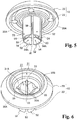
Fig. 5 is a perspective view showing a grommet of the two-piece clip according to one embodiment of the present invention, and viewed from a body portion side. -
Fig. 6 is a perspective view showing the grommet of the two-piece clip according to one embodiment of the present invention, and viewed from a base portion side. -
Fig. 7 is a perspective view showing a pin of the two-piece clip according to one embodiment of the present invention. -
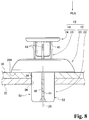
Fig. 8 is a side view showing the minimum push-in position in the state wherein the two-piece clip according to one embodiment of the present invention is placed in the members. - Next, one embodiment of a two-piece clip of the present invention will be explained according to
Figs. 1 to 8 . Incidentally, in the figures, an arrow PUS indicates an insertion direction of the two-piece clip into an attachment hole, and an insertion direction of a pin into a grommet. - Next, a configuration of a two-
piece clip 10 of the present embodiment will be explained. - As shown in
Fig 8 , the two-piece clip 10 of the present embodiment is made of synthetic resin, and comprises agrommet 12 and apin 14. Also, thegrommet 12 includes abase portion 20 and abody portion 22, and thepin 14 includes ahead portion 24 and anaxis portion 26. - As shown in
Fig. 5 and Fig. 6 , thebase portion 20 of thegrommet 12 has a disk shape. Incidentally, as shown inFig. 8 , thebase portion 20 of thegrommet 12 has a size preventing thebase portion 20 of thegrommet 12 from entering into attachment holes 34 and 36 of two ormore members piece clip 10. Also, aback face 20A, which is a face on a protruding side of thebody portion 22 in thebase portion 20 of thegrommet 12, is a face orthogonal to acenter axis 23 of thebody portion 22. - As shown in
Fig. 2 , thebody portion 22 of thegrommet 12 can be inserted and passed through the attachment holes 34 and 36 of themembers back face 20A of thebase portion 20 abuts against anexternal surface 30A of themember 30 which is located on a side just in front of an insertion. Also, in a central portion of thebase portion 20 of thegrommet 12, there is provided aninsertion hole 27 in a passing-through state, and in theinsertion hole 27, there is inserted theaxis portion 26 of thepin 14. Also, theinsertion hole 27 is formed in a bottom 31A of aconcave portion 31 having a circular inner outline shape formed in the center of thebase portion 20 of thegrommet 12. - The
insertion hole 27 has a size preventing thehead portion 24 of thepin 14 from entering in, and theinsertion hole 27 is communicated with aspace 29 inside thebody portion 22 of thegrommet 12. Also, theconcave portion 31 has a size allowing thehead portion 24 of thepin 14 to be housed, and a depth larger than a thickness of thehead portion 24 of thepin 14. - Therefore, when the
pin 14 is pushed into the standard position shown inFig. 3 from a minimum push-in position shown inFig. 2 , thehead portion 24 of thepin 14 approximately comes to the same position as atop portion 20B of thebase portion 20 of thegrommet 12 so as not to be capable of protruding from theconcave portion 31. - As shown in
Fig. 5 , thebody portion 22 of thegrommet 12 splits into two or more (four in the present embodiment) body-portion configuration pieces 52 byslits 50 ranging from a tip thereof to a base. Also, thebody portion 22 has a cylindrical body whose both ends are open, and one end thereof is integrated with theback face 20A of thebase portion 20 such that a cylinder inner space is communicated with theinsertion hole 27. - The
slits 50 are formed ranging from one end (the tip) to the other end (the base) of thebody portion 22 having the cylindrical body. Theslits 50 are provided with four portions opening approximately with an equal interval between theslits 50 next to each other in a circling direction of the cylindrical body. Thereby, thebody portion 22 of thegrommet 12 splits into four body-portion configuration pieces 52. - As shown in
Fig. 2 , on a tip side of each body-portion configuration piece 52 of thegrommet 12, there is formed an engagementconvex portion 54. In a formation position of the engagementconvex portion 54, an inside diameter of thespace 29 inside thebody portion 22 is made smaller than a maximum diameter of theaxis portion 26 of thepin 14. Also, the inside diameter of thespace 29 inside thebody portion 22 from the formation position of the engagementconvex portion 54 to thebase portion 20 is configured to be approximately equal to the maximum diameter of theaxis portion 26 of thepip 14. - The engagement
convex portion 54 of thegrommet 12 includes a tip-side convexportion wall surface 54A inclining in an inner direction from an outside of thebody portion 22 toward abase portion 20 side from a tip side (the opposite side of the base portion 20) of thebody portion 22; and a head portion-side convexportion wall surface 54B inclining in the inner direction from the outside of thebody portion 22 toward the tip side from a base side (thebase portion 20 side) of thebody portion 22. Also, from an inner end of the engagementconvex portion 54, there is formed a top-portion projection 54C (a convex portion) as the convex portion protruding inwardly (the inner direction of the body portion 22). Incidentally, a cross-sectional shape along an axis direction of thegrommet 12 of the top-portion projection 54C has a curved shape (a rounded shape). - As shown in
Fig. 6 , in a hole edge portion of theinsertion hole 27 in thebase portion 20 of thegrommet 12, there are formed guideconcave portions 33 with four portions mutually opening approximately at an equal interval in a circling direction thereof. Also, a bottom surface of the guideconcave portions 33 inclines in a direction gradually projecting to a center side of thebase portion 20 toward aback surface 20A side from atop portion 20B side of thebase portion 20. Then, the guideconcave portions 33 end leaving climbing-overportions 33A with respect to a terminating end of theslit 50. - As shown in
Fig. 7 , theaxis portion 26 of thepin 14 has a round bar-shaped body whose end narrows. Also, approximately in a middle position in a direction along anaxis line 14A in theaxis portion 26 of thepin 14, there is formed a head portion-side engagementconcave portion 44, and on a tip side adjoining the head portion-side engagementconcave portion 44, there is formed a tip-side engagementconcave portion 40. The head portion-side engagementconcave portion 44 is made deeper (larger) than the tip-side engagementconcave portion 40. Although the engagementconvex portion 54 of thegrommet 12 cannot be completely entered into the tip-side engagementconcave portion 40 of thepin 14, the engagementconvex portion 54 of thegrommet 12 can be completely entered into the head portion-side engagementconcave portion 44. Also, in a tip side more than the tip-side engagementconcave portion 40 in theaxis portion 26 of thepin 14, there are formed retainingsmall projections 41, and near thehead portion 24 in theaxis portion 26 of thepin 14, there are formed head portion-sidesmall projections 43. - As shown in
Fig. 4 , the head portion-side engagementconcave portion 44 has a concave-portion inside shape following an outline shape of the engagementconvex portion 54 of the body-portion configuration piece 52 in thegrommet 12. - As shown in
Fig. 7 , the head portion-side engagementconcave portion 44 is provided with four portions opening approximately at an equal interval between the head portion-side engagement concaveportions 44 next to each other in a circling direction of theaxis portion 26 of thepin 14. Also, in the head portion-side engagementconcave portion 44, both a tip-side concaveportion wall surface 44A, and a head portion-side concaveportion wall surface 44C continuing to the tip-side concaveportion wall surface 44A through acontinuous axis portion 44B have an inclined surface. - On the other hand, the tip-side engagement concave
portions 40 of thepin 14 are formed only in portions adjoining the two head portion-side engagement concaveportions 44, which are located in an opposed position sandwiching the center of theaxis portion 26. Also, the tip-side engagement concaveportions 40 have a shallow rectangular depression long in the circling direction of theaxis portion 26 to allow only the top-portion projection 54C of the engagementconvex portion 54 to be entered therein. - Therefore, as shown in
Fig. 3 , when thepin 14 is pushed into the standard position, the engagementconvex portion 54 of thegrommet 12 enters into the tip-side engagementconcave portion 40 of thepin 14, and thebody portion 22 of thegrommet 12, i.e., each body-portion configuration piece 52 can elastically deform outward. As a result, themembers portion configuration piece 52 and thebase portion 20 of thegrommet 12, and themembers Fig. 4 , when thepin 14 is pushed into the maximum push-in position, the engagementconvex portion 54 of thegrommet 12 enters into the head portion-side engagementconcave portion 44. - Namely, the
axis portion 26 of thepin 14 which is in the standard position is further pushed into the maximum push-in position using thehead portion 24, so that each body-portion configuration piece 52 of thegrommet 12, which has bended outward in the standard position, is elastically returned into the head portion-side engagementconcave portion 44 so as to be capable of resolving the fastening of theaxis portion 26 of thepin 14 into the attachment holes 34 and 36. Thereby, the two-piece clip 10 can be extracted and removed from the attachment holes 34 and 36. - Incidentally, as shown in
Fig. 3 , in a state wherein theaxis portion 26 of thepin 14 is pushed into thegrommet 12 up to the standard position, thehead portion 24 of thepin 14 does not protrude from theconcave portion 31 of thebase portion 20 of thegrommet 12, so that in the standard position, thehead portion 24 of thepin 14 is not unexpectedly pushed, and theaxis portion 26 is pushed in up to the maximum push-in position so as to be incapable of resolving the fastening relative to the attachment holes 34 and 36. - As shown in
Fig. 1 , the tip-side concaveportion wall surface 44A of the head portion-side engagementconcave portion 44 of thepin 14 inclines in an inner direction from an outside of theaxis portion 26 toward ahead portion 24 side from a tip side of thepin 14. Also, the head portion-side concaveportion wall surface 44C of the head portion-side engagementconcave portion 44 of thepin 14 inclines in the inner direction from the outside of theaxis portion 26 toward the tip side from thehead portion 24 side of thepin 14. Also, in a state wherein the top-portion projection 54C of the engagementconvex portion 54 of thegrommet 12 has been completely entered in the head portion-side engagementconcave portion 44 of theaxis portion 26 of the pin 14 (the maximum push-in position), an inner end of the tip-side convexportion wall surface 54A of the engagementconvex portion 54 abuts against a middle of the tip-side concaveportion wall surface 44A of the head portion-side engagementconcave portion 44. - Therefore, as shown in
Fig. 1 , in the maximum push-in position, when a tip portion of thepin 14 is pushed back in an extracting direction (an arrow A direction inFig. 1 ), the tip-side concaveportion wall surface 44A of the head portion-side engagementconcave portion 44 of thepin 14 slides against the inner end of the tip-side convexportion wall surface 54A of the engagementconvex portion 54 of thegrommet 12 so as to easily elastically deform each body-portion configuration piece 52 of thegrommet 12 in an outer direction (arrow B directions inFig. 1 ). Namely, by a force pushing the tip portion of thepin 14 back in the extracting direction, the tip-side concaveportion wall surface 44A of the head portion-side engagementconcave portion 44 in thepin 14 slides against the inner end of the tip-side convexportion wall surface 54A of the engagementconvex portion 54 of thegrommet 12 so as to be capable of easily spreading the engagementconvex portion 54 of thegrommet 12 in the outer direction. Consequently, by a simple operation of pushing the tip portion of thepin 14 back in the extracting direction, and by the operation capable of reducing an operational force, thepin 14 can be returned to the minimum push-in position (a reusable position) from the maximum push-in position shown inFig. 1 relative to thegrommet 12 through the standard position. - As shown in
Fig. 7 , both the retainingsmall projections 41 and the head portion-sidesmall projections 43 of thepin 14 are provided on imaginary straight lines L along theaxis line 14A of thepin 14 passing between the head portion-side engagement concaveportions 44 next to each other. Incidentally, the retainingsmall projections 41 are provided with two portions on both sides in a diametrical direction of theaxis portion 26, and the head portion-sidesmall projections 43 are provided with four portions. - Therefore, the guide concave portions 33 (see
Fig. 6 ) of thegrommet 12 allow theaxis portion 26 of thepin 14 to enter into thebody portion 22 of thegrommet 12 through theinsertion hole 27 of thegrommet 12 only in a direction allowing the retainingsmall projections 41 of thepin 14 to be entered. By the inserting operation, the retainingsmall projections 41 elastically deform, and climb over the climbing-overportions 33A so as to be entered into theslits 50. - In the minimum push-in position (the reusable position shown in
Fig. 2 , theaxis portion 26 does not allow the body-portion configuration pieces 52 outward, and thebody portion 22 of thegrommet 12 and theaxis portion 26 of thepin 14 are not engaged. However, the retainingsmall projections 41 of thepin 14 shown inFig. 7 are caught on the terminating end of theslit 50, so that even if theaxis portion 26 is not pushed in up to the standard position, theaxis portion 26 of thepin 14 cannot be completely extracted from thebody portion 26 of thepin 14. - Also, when the
axis portion 26 of thepin 14 is pushed in up to a complete push-in position from the standard position, the head portion-sidesmall projections 43 of thepin 14 elastically deform, and climb over the climbing-overportions 33A of thegrommet 12 so as to be entered into theslits 50. Incidentally, since a configuration of the aforementioned portion is well-known, a detailed explanation will be omitted. - As shown in
Fig. 3 , an innerperipheral portion 22A of thebody portion 22 of thegrommet 12 and an outerperipheral portion 26A of theaxis portion 26 of thepin 14 contact with each other on a surface extending in the direction along theaxis line 14A of thepin 14. Consequently, the innerperipheral portion 22A of thebody portion 22 of thegrommet 12 and the outerperipheral portion 26A of theaxis portion 26 of thepin 14 are closely attached on the surface extending in the direction along theaxis line 14A of thepin 14. Therefore, in a state wherein themembers piece clip 10 so as not to be separated, a contact area of the innerperipheral portion 22A of thebody portion 22 of thegrommet 12 relative the outerperipheral portion 26A of theaxis portion 26 of thepin 14 increases, so that thepin 14 becomes hard to be extracted relative to thegrommet 12 so as to improve a removal resistance force. - As shown in
Fig. 1 , an inclination (initial rise) angle α1 relative to theaxis line 14A of thepin 14 of the head portion-side concaveportion wall surface 44C in the head portion-side engagementconcave portion 44 formed in thepin 14 has a wide angle (α1 > α2) compared to an inclination (initial rise) angle α2 relative to theaxis line 14A of thepin 14 of the tip-side concaveportion wall surface 44A in the head portion-side engagementconcave portion 44 formed in thepin 14. Therefore, a range, wherein the innerperipheral portion 22A of thebody portion 22 of thegrommet 12 and the outerperipheral portion 26A of theaxis portion 26 of thepin 14 are closely attached, can be increased long toward the tip side of thepin 14. Also, the contact area of the innerperipheral portion 22A of thebody portion 22 of thegrommet 12 relative to the outerperipheral portion 26A of theaxis portion 26 of thepin 14 increases. Consequently, in the state wherein themembers piece clip 10 so as not to be separated, thepin 14 becomes hard to be extracted relative to thegrommet 12 so as to improve a removal resistance. - Also, the inclination (initial rise) angle α2 relative to the
axis line 14A of thepin 14 of the tip-side concaveportion wall surface 44A in the head portion-side engagementconcave portion 44 formed in thepin 14 has a narrow angle (α2 < α3) compared to an inclination (initial rise) angle α3 relative to theaxis line 14A of thepin 14 of the tip-side convexportion wall surface 54A in the engagementconvex portion 54 formed in thegrommet 12. Therefore, in a state wherein the engagementconvex portion 54 of thegrommet 12 abuts against the tip-side concaveportion wall surface 44A of the head portion-side engagementconcave portion 44, agap 60 can be formed between thepin 14 and thegrommet 12. Consequently, a contact portion of thepin 14 relative to thegrommet 12 is reduced, so that a force applied to the tip of thepin 14 concentrates on the contact portion of thepin 14 and thegrommet 12 so as to be easily transmitted to a grommet side. - Next, an attachment procedure of the two-
piece clip 10 of the present embodiment will be explained. - As shown in
Fig. 2 , the two-piece clip 10 which is in the minimum push-in position (the usable position), wherein a tip portion of theaxis portion 26 of thepin 14 is entered into thebody portion 22 of thegrommet 12, is inserted into the attachment holes 34 and 36 of themembers piece clip 10 is inserted and passed through the attachment holes 34 and 36 of themembers back face 20A of thebase portion 20 contacts with the external surface of themember 30 which is located on the side just in front of the insertion. - Next, as shown in
Fig. 3 , theaxis portion 26 of thepin 14 is pushed into thebody portion 22 of thegrommet 12 so as to enter in the standard position. Thereby, the engagementconvex portion 54 of thegrommet 12 is entered into the tip-side engagementconcave portion 40 of thepin 14, so that thebody portion 22 of thegrommet 12, i.e., each body-portion configuration piece 52 elastically deforms outward. As a result, themembers portion configuration piece 52 and thebase portion 20 of thegrommet 12, and themembers - Next, a removal procedure of the two-
piece clip 10 of the present embodiment will be explained. - As shown in
Fig. 3 , from the state (the standard position) wherein themembers piece clip 10 of the present embodiment so as not to be separated, thehead portion 24 of thepin 14 is pushed in so as to enter into the maximum push-in position shown inFig. 4 . Thereby, the body-portion configuration piece 52 of thegrommet 12 elastically deforms outward once, and an engagement between the tip-side engagementconcave portion 40 of theaxis portion 26 of thepin 14 and the engagementconvex portion 54 of thegrommet 12 is released. After that, the body-portion configuration piece 52 of thegrommet 12 is elastically returned, and the engagementconvex portion 54 of thegrommet 12 enters into the head portion-side engagementconcave portion 44 of thepin 14, so that a fastening state of thegrommet 12 relative to the attachment holes 34 and 36 is released. Consequently, the two-piece clip 10 is extracted from the attachment holes 34 and 36 so as to be capable of being removed. - Next, a return procedure to a reusable state of the two-
piece clip 10 of the present embodiment will be explained. - First, as shown in
Fig. 1 , the tip portion of thepin 14 of the two-piece clip 10 which is in the maximum push-in position is pushed back in the extracting direction (the arrow A direction inFig. 1 ) relative to thegrommet 12. At that time, only the inner end of the tip-side convexportion wall surface 54A of the engagementconvex portion 54 of thegrommet 12 abuts against the middle of the tip-side concaveportion wall surface 44A of the head portion-side engagementconcave portion 44 in thepin 14. - Consequently, the tip-side concave
portion wall surface 44A of the head portion-side engagementconcave portion 44 in thepin 14 slides against the inner end of the tip-side convexportion wall surface 54A of the engagementconvex portion 54 of thegrommet 12 so as to easily elastically deform each body-portion configuration piece 52 of thegrommet 12 outward. - Namely, by the force pushing the tip portion of the
pin 14 back in the extracting direction, the tip-side concaveportion wall surface 44A of the head portion-side engagementconcave portion 44 in thepin 14 slides against the inner end of the tip-side convexportion wall surface 54A of the engagementconvex portion 54 of thegrommet 12 so as to easily spread the engagementconvex portion 54 of thegrommet 12. As a result, thepin 14 moves in the extracting direction (the arrow A direction inFig. 1 ) relative to thegrommet 12, and through the standard position, thepin 14 is returned to the minimum push-in position (the reusable state). - As above, in the two-
piece clip 10 of the present embodiment, as shown inFig. 1 , in the maximum push-in position, the inner end of the tip-side convexportion wall surface 54A of the engagementconvex portion 54 of thegrommet 12 abuts against the middle of the tip-side concaveportion wall surface 44A of the head portion-side engagementconcave portion 44 in thepin 14. Consequently, when the tip portion of thepin 14 is pushed back in the extracting direction (the arrow A direction inFig. 1 ), the tip-side concaveportion wall surface 44A of the head portion-side engagementconcave portion 44 of thepin 14 slides against the inner end of the tip-side convexportion wall surface 54A of the engagementconvex portion 54 of thegrommet 12 so as to easily elastically deform each body-portion configuration piece 52 of thegrommet 12 in the outer direction (the arrow B direction inFig. 1 ). Namely, by the force pushing the tip portion of thepin 14 back in the extracting direction, the tip-side concaveportion wall surface 44A of the head portion-side engagementconcave portion 44 in thepin 14 slides against the inner end of the tip-side convexportion wall surface 54A of the engagementconvex portion 54 of thegrommet 12 so as to easily spread the engagementconvex portion 54 of thegrommet 12 in the outer direction. Consequently, by the simple operation of pushing the tip portion of thepin 14 back in the extracting direction, and by the operation capable of reducing the operational force, thepin 14 can be returned to the minimum push-in position (the reusable state) from the maximum push-in position shown inFig. 1 relative to thegrommet 12 through the standard position. - Also, in the two-
piece clip 10 of the present embodiment, as shown inFig. 3 , the innerperipheral portion 22A of thebody portion 22 of thegrommet 12 and the outerperipheral portion 26A of theaxis portion 26 of thepin 14 contact with each other on the surface extending in the direction along theaxis line 14A of thepin 14. Consequently, the innerperipheral portion 22A of thebody portion 22 of thegrommet 12 and the outerperipheral portion 26A of theaxis portion 26 of thepin 14 are closely attached on the surface extending in the direction along theaxis line 14A of thepin 14, and the contact area of the innerperipheral portion 22A of thebody portion 22 of thegrommet 12 relative to the outerperipheral portion 26A of theaxis portion 26 of thepin 14 increases. As a result, in the state wherein themembers piece clip 10 so as not to be separated, thepin 14 becomes hard to be extracted relative to thegrommet 12 so as to improve the removal resistance force. - Also, in the two-
piece clip 10 of the present embodiment, as shown inFig. 1 , the inclination angle α1 relative to theaxis line 14A of thepin 14 of the head portion-side concaveportion wall surface 44C of the head portion-side engagementconcave portion 44 formed in thepin 14 has the wide angle (α1 > α2) compared to the inclination angle α2 relative to theaxis line 14A of thepin 14 of the tip-side concaveportion wall surface 44A of the head portion-side engagementconcave portion 44 formed in thepin 14. Consequently, a closely attached portion of the innerperipheral portion 22A of thebody portion 22 of thegrommet 12 relative to the outerperipheral portion 26A of theaxis portion 26 of thepin 14 can be extended long toward the tip side of thepin 14. Also, the contact area of the innerperipheral portion 22A of thebody portion 22 of thegrommet 12 relative to the outerperipheral portion 26A of theaxis portion 26 of thepin 14 can be increased. As a result, in the state wherein themembers pin 14 becomes hard to be extracted relative to thegrommet 12 so as to improve the removal resistance. - Also, the inclination angle α2 relative to the
axis line 14A of thepin 14 of the tip-side concaveportion wall surface 44A of the head portion-side engagementconcave portion 44 formed in thepin 14 has the narrow angle (α2 < α3) compared to the inclination angle α3 relative to theaxis line 14A of thepin 14 of the tip-side convexportion wall surface 54A of the engagementconvex portion 54 formed in thegrommet 12. Consequently, thegap 60 can be formed between thepin 14 and thegrommet 12, and the contact portion of thepin 14 relative to thegrommet 12 is reduced, so that the force applied to the tip of thepin 14 concentrates on the contact portion of thepin 14 relative to thegrommet 12 so as to be easily transmitted to the grommet side. As a result, the operational force when thepin 14 is returned to the reusable position relative to thegrommet 12 can be reduced so as to further improve a workability. - Also, in the two-
piece clip 10 of the present embodiment, in the inner end of the engagementconvex portion 54 of thegrommet 12, there is formed the top-portion projection 54C having the curved shape (the rounded shape). Consequently, in the maximum push-in position, the tip portion of thepin 14 is pushed back in the extracting direction (the arrow A direction inFig. 1 ), and thebody portion 22 of thegrommet 12 elastically deforms outward. When the tip-side concaveportion wall surface 44A of the head portion-side engagementconcave portion 44 of thepin 14 slides against the top-portion projection 54C of the inner end of the engagementconvex portion 54 of thegrommet 12, thepin 14 can easily slide against thegrommet 12. As a result, the operational force when thepin 14 is returned to the reusable position relative to thegrommet 12 can be reduced so as to further improve the workability when thepin 14 is returned to the reusable position relative to thegrommet 12. - In the above, a specific embodiment of the present invention has been explained in detail. However, the present invention is not limited to the aforementioned embodiment, and it is obvious for a person skilled in the art that other various embodiments can be carried out within the scope of the present invention. For example, in the aforementioned embodiment, although the two-
piece clip 10 is made of synthetic resin, a material of the two-piece clip 10 is not limited to the synthetic resin. Also, the material of thegrommet 12 and the material of thepin 14 may be a different material. Moreover, in the two-piece clip 10 of the aforementioned embodiment, three or more members may be fastened together.
Claims (4)
- A two-piece clip (10), comprising:a grommet (12) including a body portion (22) split by two or more slits (50) extending from a tip to a base, formed of an engagement convex portion (54) in the tip, and insertable into attachment holes (34, 36) of overlapped members (30, 32), and a base portion (20) provided in the base of the body portion (22), and abuttable against a peripheral edge portion of the attachment holes (34, 36) of the members (30, 32);a pin (14) including an axis portion (26) which can be pushed into the body portion (22) of the grommet (12), and a head portion (24) provided in one end portion of the axis portion (26);a tip-side engagement concave portion (40) formed in the axis portion (26) of the pin (14), and engaged with the engagement convex portion (54) of the grommet (12) in a standard position where the pin (14) is pushed into the grommet (12) with a predetermined amount, to elastically deform the body portion (22) of the grommet (12) outward so as to clamp the members (30, 32) by the body portion (22) and the base portion (20); anda head portion-side engagement concave portion (44) formed in a head portion side is made deeper than the tip-side engagement concave portion (40) in the axis portion (26) of the pin (14), and engaged with the engagement convex portion (54) of the body portion (22) in a maximum push-in position where the pin (14) is pushed into the grommet (12) further than the standard position, to elastically return the body portion (22) of the grommet (12) inward so as to pass through the attachment holes (34, 36),wherein the engagement convex portion (54) of the grommet (12) includes a tip-side convex portion wall surface (54A) inclining in an inner direction of the body portion (22) from a tip side of the body portion (22), and a base portion-side convex portion wall surface (54B) inclining in an inner direction of the body portion (22) from a base portion side of the grommet (12),the head portion-side engagement concave portion (44) of the pin (14) includes a tip-side concave portion wall surface (44A) inclining in an inner direction of the axis portion (26) from the tip side, and a head portion-side concave portion wall surface (44C) inclining in the inner direction of the axis portion (26) from the head portion side of the pin (14), andin the maximum push-in position, an inner end of the tip-side convex portion wall surface (54A) of the engagement convex portion (54) abuts against a middle of the tip-side concave portion wall surface (44A) of the head portion-side engagement concave portion (44),whereby an inclination angle (α2) relative to an axis line (14A) of the pin (14) of the tip-side concave portion wall surface (44A) of the head portion-side engagement concave portion (44) formed in the pin (14) has a narrow angle (α2 < α3) compared to an inclination angle (α3) relative to the axis line (14A) of the pin (14) of the tip-side convex portion wall surface (54A) of the engagement convex portion (54) formed in the grommet (12),characterized in thatan inclination angle (α1) relative to the axis line (14A) of the pin (14) of the head portion-side concave portion wall surface (44C) of the head portion-side engagement concave portion (44) formed in the pin (14) has a wide angle (α1 > α2) compared to an inclination angle (α2) relative to the axis line (14A) of the pin (14) of the tip-side concave portion wall surface (44A) of the head portion-side engagement concave portion (44) formed in the pin (14).
- A two-piece clip (10) according to claim 1, wherein an inner peripheral portion (22A) of the body portion (22) of the grommet (12) and an outer peripheral portion (26A) of the axis portion (26) of the pin (14) mutually contact on a surface extending in a direction along an axis line (14A) of the pin (14) .
- A two-piece clip (10) according to claim 1 or 2, wherein a convex portion having a curved shape is formed in an inner end of the engagement convex portion (54) of the grommet (12).
- A two-piece clip (10) according to any one of claims 1 to 3, wherein retaining small projections (41) and head portion-side small projections (43) of the pin (14) are provided on imaginary straight lines (L) along the axis line (14A) of the pin (14) passing between the head portion-side engagement concave portions (44) next to each other.
Applications Claiming Priority (2)
| Application Number | Priority Date | Filing Date | Title |
|---|---|---|---|
| JP2010288942A JP5701593B2 (en) | 2010-12-24 | 2010-12-24 | 2 piece clip |
| PCT/JP2011/079549 WO2012086652A1 (en) | 2010-12-24 | 2011-12-20 | Two-piece clip |
Publications (3)
| Publication Number | Publication Date |
|---|---|
| EP2657545A1 EP2657545A1 (en) | 2013-10-30 |
| EP2657545A4 EP2657545A4 (en) | 2018-01-03 |
| EP2657545B1 true EP2657545B1 (en) | 2021-09-08 |
Family
ID=46313920
Family Applications (1)
| Application Number | Title | Priority Date | Filing Date |
|---|---|---|---|
| EP11850490.1A Active EP2657545B1 (en) | 2010-12-24 | 2011-12-20 | Two-piece clip |
Country Status (6)
| Country | Link |
|---|---|
| US (1) | US9103363B2 (en) |
| EP (1) | EP2657545B1 (en) |
| JP (1) | JP5701593B2 (en) |
| KR (1) | KR101481360B1 (en) |
| CN (1) | CN103270323B (en) |
| WO (1) | WO2012086652A1 (en) |
Families Citing this family (22)
| Publication number | Priority date | Publication date | Assignee | Title |
|---|---|---|---|---|
| JP5336284B2 (en) * | 2009-07-15 | 2013-11-06 | 株式会社ニフコ | 2 piece clip |
| JP5901195B2 (en) * | 2011-09-16 | 2016-04-06 | 株式会社ニフコ | Fastener |
| JP6126958B2 (en) * | 2013-09-19 | 2017-05-10 | 株式会社ニフコ | clip |
| AU2014359722B2 (en) | 2013-12-02 | 2016-08-11 | Aesculap Ag | Security seal for medical sterile container |
| AT515173B1 (en) * | 2013-12-13 | 2016-11-15 | Ultimate Europe Transp Equipment Gmbh | fastening system |
| US9528540B2 (en) * | 2014-08-12 | 2016-12-27 | Newfrey Llc | Insertion-locking pin and grommet and related methods |
| US10030682B2 (en) | 2014-08-25 | 2018-07-24 | Ford Global Technologies, Llc | Two-part fastener |
| DE202015104382U1 (en) | 2015-08-25 | 2015-09-08 | Ford Global Technologies, Llc | Two-piece fastener |
| JP6396277B2 (en) * | 2015-11-26 | 2018-09-26 | 株式会社ニフコ | clip |
| US9873388B2 (en) * | 2016-04-06 | 2018-01-23 | Newfrey Llc | Automotive door trim fastener and molding method |
| GB2551367B (en) * | 2016-06-15 | 2019-03-27 | Ford Motor Co | Temporary fastener assembly |
| JP6669623B2 (en) * | 2016-09-23 | 2020-03-18 | 株式会社ニフコ | Member mounting structure and mounting clip |
| CN111033062B (en) * | 2017-08-24 | 2021-08-20 | 株式会社利富高 | Card holder |
| JP6850773B2 (en) * | 2018-08-22 | 2021-03-31 | 株式会社ニフコ | clip |
| JP6547237B1 (en) | 2019-02-26 | 2019-07-24 | 千住金属工業株式会社 | Soldering apparatus and method for fixing packing to soldering apparatus |
| CN111664153A (en) * | 2019-03-08 | 2020-09-15 | 伊利诺斯工具制品有限公司 | Rivet type fastener |
| US10900513B2 (en) | 2019-04-02 | 2021-01-26 | Newfrey Llc | Re-usable one-push pin and grommet fastener |
| CN111609013A (en) * | 2020-05-29 | 2020-09-01 | 京信通信技术(广州)有限公司 | Retaining rivet and antenna |
| US20220065281A1 (en) * | 2020-09-03 | 2022-03-03 | Milbank Manufacturing Co. | Plumb adjuster for electrical enclosure |
| CN112924003B (en) * | 2021-01-25 | 2022-08-26 | 柴沙沙 | Electronic balance for basic mathematics |
| CN115370649A (en) * | 2021-05-19 | 2022-11-22 | 伊利诺斯工具制品有限公司 | Grommet and fastener assembly |
| US20230323908A1 (en) * | 2022-04-08 | 2023-10-12 | Toyota Motor Engineering & Manufacturing North America, Inc. | Coupling Assemblies Having Frangible Portions |
Family Cites Families (16)
| Publication number | Priority date | Publication date | Assignee | Title |
|---|---|---|---|---|
| JPH0442568Y2 (en) * | 1985-06-19 | 1992-10-08 | ||
| JPH032003Y2 (en) * | 1986-09-26 | 1991-01-21 | ||
| JPS6414912U (en) * | 1987-07-16 | 1989-01-25 | ||
| JPH0524807Y2 (en) * | 1987-12-04 | 1993-06-23 | ||
| JPH0247414U (en) * | 1988-09-29 | 1990-03-30 | ||
| AU626479B2 (en) * | 1989-12-12 | 1992-07-30 | W.A. Deutsher Pty Ltd | Two part fastener |
| US5201623A (en) * | 1992-02-18 | 1993-04-13 | Emhart Inc. | Two stage rivet |
| JP3265103B2 (en) * | 1994-01-24 | 2002-03-11 | ポップリベット・ファスナー株式会社 | Plastic blind rivets |
| JP2004028244A (en) * | 2002-06-27 | 2004-01-29 | Nippon Pop Rivets & Fasteners Ltd | Clip and member coupler |
| JP4091859B2 (en) * | 2003-03-03 | 2008-05-28 | 株式会社パイオラックス | Fastener |
| US7736107B2 (en) * | 2004-03-30 | 2010-06-15 | Piolax, Inc. | Clipping device |
| JP4485281B2 (en) * | 2004-08-05 | 2010-06-16 | 株式会社ニフコ | Fastener |
| DE102005021940A1 (en) * | 2005-05-12 | 2006-11-30 | Volkswagen Ag | Connector, e.g. for vehicle cladding, has base fitted with arms that can be fitted into bore of elements to be connected and pin fitted with arrangement for aligning arms that is designed to reversibly connect pin |
| JP4520920B2 (en) * | 2005-08-22 | 2010-08-11 | 株式会社ニフコ | clip |
| JP4423266B2 (en) | 2006-01-25 | 2010-03-03 | 株式会社ニフコ | Grommet |
| CN101688549B (en) * | 2007-07-12 | 2011-11-30 | 百乐仕株式会社 | Latching device |
-
2010
- 2010-12-24 JP JP2010288942A patent/JP5701593B2/en active Active
-
2011
- 2011-12-20 US US13/997,502 patent/US9103363B2/en active Active
- 2011-12-20 CN CN201180062331.2A patent/CN103270323B/en active Active
- 2011-12-20 EP EP11850490.1A patent/EP2657545B1/en active Active
- 2011-12-20 WO PCT/JP2011/079549 patent/WO2012086652A1/en active Application Filing
- 2011-12-20 KR KR1020137019203A patent/KR101481360B1/en active IP Right Grant
Also Published As
| Publication number | Publication date |
|---|---|
| CN103270323A (en) | 2013-08-28 |
| WO2012086652A1 (en) | 2012-06-28 |
| CN103270323B (en) | 2015-08-12 |
| US20130287517A1 (en) | 2013-10-31 |
| KR101481360B1 (en) | 2015-01-21 |
| EP2657545A1 (en) | 2013-10-30 |
| KR20130115329A (en) | 2013-10-21 |
| EP2657545A4 (en) | 2018-01-03 |
| JP2012137130A (en) | 2012-07-19 |
| US9103363B2 (en) | 2015-08-11 |
| JP5701593B2 (en) | 2015-04-15 |
Similar Documents
| Publication | Publication Date | Title |
|---|---|---|
| EP2657545B1 (en) | Two-piece clip | |
| EP2600013B1 (en) | Grommet | |
| JP5081759B2 (en) | clip | |
| US8038486B1 (en) | Connector | |
| US9373901B2 (en) | Spring clip for shielding of electrical connectors | |
| EP2543895B1 (en) | Push rivet | |
| KR20070014032A (en) | String holder | |
| JP2007315517A (en) | Two piece clip | |
| US9577366B2 (en) | Waterproof connector having an elastic seal member with the engaged portion | |
| US11649912B2 (en) | Pipe connector | |
| US20180178735A1 (en) | Member attachment structure and attachment clip | |
| KR20160047370A (en) | Clip | |
| JP4040451B2 (en) | End cover of string or band | |
| WO2014088043A1 (en) | Hole plug | |
| EP3834775A1 (en) | Intraocular lens insertion implement | |
| CN111033062B (en) | Card holder | |
| JP5210207B2 (en) | Assembly structure of clip and mounting member | |
| KR20170015148A (en) | Fastener | |
| WO2012157614A1 (en) | Hole plug | |
| JP2010092689A (en) | Electrical connector | |
| JP2012082955A (en) | Clip | |
| TWI726392B (en) | buckle | |
| KR102191891B1 (en) | Clip and connector assembly | |
| KR101629090B1 (en) | Clip | |
| WO2017150121A1 (en) | Connector |
Legal Events
| Date | Code | Title | Description |
|---|---|---|---|
| PUAI | Public reference made under article 153(3) epc to a published international application that has entered the european phase |
Free format text: ORIGINAL CODE: 0009012 |
|
| 17P | Request for examination filed |
Effective date: 20130708 |
|
| AK | Designated contracting states |
Kind code of ref document: A1 Designated state(s): AL AT BE BG CH CY CZ DE DK EE ES FI FR GB GR HR HU IE IS IT LI LT LU LV MC MK MT NL NO PL PT RO RS SE SI SK SM TR |
|
| DAX | Request for extension of the european patent (deleted) | ||
| RA4 | Supplementary search report drawn up and despatched (corrected) |
Effective date: 20171130 |
|
| RIC1 | Information provided on ipc code assigned before grant |
Ipc: F16B 19/10 20060101AFI20171124BHEP Ipc: F16B 5/06 20060101ALI20171124BHEP Ipc: F16B 5/00 20060101ALI20171124BHEP |
|
| STAA | Information on the status of an ep patent application or granted ep patent |
Free format text: STATUS: EXAMINATION IS IN PROGRESS |
|
| 17Q | First examination report despatched |
Effective date: 20200326 |
|
| STAA | Information on the status of an ep patent application or granted ep patent |
Free format text: STATUS: EXAMINATION IS IN PROGRESS |
|
| GRAP | Despatch of communication of intention to grant a patent |
Free format text: ORIGINAL CODE: EPIDOSNIGR1 |
|
| STAA | Information on the status of an ep patent application or granted ep patent |
Free format text: STATUS: GRANT OF PATENT IS INTENDED |
|
| INTG | Intention to grant announced |
Effective date: 20210412 |
|
| GRAS | Grant fee paid |
Free format text: ORIGINAL CODE: EPIDOSNIGR3 |
|
| GRAA | (expected) grant |
Free format text: ORIGINAL CODE: 0009210 |
|
| STAA | Information on the status of an ep patent application or granted ep patent |
Free format text: STATUS: THE PATENT HAS BEEN GRANTED |
|
| RIN1 | Information on inventor provided before grant (corrected) |
Inventor name: FUJIWARA, KENSUKE |
|
| AK | Designated contracting states |
Kind code of ref document: B1 Designated state(s): AL AT BE BG CH CY CZ DE DK EE ES FI FR GB GR HR HU IE IS IT LI LT LU LV MC MK MT NL NO PL PT RO RS SE SI SK SM TR |
|
| RAP3 | Party data changed (applicant data changed or rights of an application transferred) |
Owner name: NIFCO INC. |
|
| REG | Reference to a national code |
Ref country code: GB Ref legal event code: FG4D |
|
| REG | Reference to a national code |
Ref country code: CH Ref legal event code: EP Ref country code: AT Ref legal event code: REF Ref document number: 1428847 Country of ref document: AT Kind code of ref document: T Effective date: 20210915 |
|
| REG | Reference to a national code |
Ref country code: DE Ref legal event code: R096 Ref document number: 602011071759 Country of ref document: DE |
|
| REG | Reference to a national code |
Ref country code: IE Ref legal event code: FG4D |
|
| REG | Reference to a national code |
Ref country code: LT Ref legal event code: MG9D |
|
| REG | Reference to a national code |
Ref country code: NL Ref legal event code: MP Effective date: 20210908 |
|
| PG25 | Lapsed in a contracting state [announced via postgrant information from national office to epo] |
Ref country code: HR Free format text: LAPSE BECAUSE OF FAILURE TO SUBMIT A TRANSLATION OF THE DESCRIPTION OR TO PAY THE FEE WITHIN THE PRESCRIBED TIME-LIMIT Effective date: 20210908 Ref country code: SE Free format text: LAPSE BECAUSE OF FAILURE TO SUBMIT A TRANSLATION OF THE DESCRIPTION OR TO PAY THE FEE WITHIN THE PRESCRIBED TIME-LIMIT Effective date: 20210908 Ref country code: FI Free format text: LAPSE BECAUSE OF FAILURE TO SUBMIT A TRANSLATION OF THE DESCRIPTION OR TO PAY THE FEE WITHIN THE PRESCRIBED TIME-LIMIT Effective date: 20210908 Ref country code: ES Free format text: LAPSE BECAUSE OF FAILURE TO SUBMIT A TRANSLATION OF THE DESCRIPTION OR TO PAY THE FEE WITHIN THE PRESCRIBED TIME-LIMIT Effective date: 20210908 Ref country code: RS Free format text: LAPSE BECAUSE OF FAILURE TO SUBMIT A TRANSLATION OF THE DESCRIPTION OR TO PAY THE FEE WITHIN THE PRESCRIBED TIME-LIMIT Effective date: 20210908 Ref country code: NO Free format text: LAPSE BECAUSE OF FAILURE TO SUBMIT A TRANSLATION OF THE DESCRIPTION OR TO PAY THE FEE WITHIN THE PRESCRIBED TIME-LIMIT Effective date: 20211208 Ref country code: BG Free format text: LAPSE BECAUSE OF FAILURE TO SUBMIT A TRANSLATION OF THE DESCRIPTION OR TO PAY THE FEE WITHIN THE PRESCRIBED TIME-LIMIT Effective date: 20211208 Ref country code: LT Free format text: LAPSE BECAUSE OF FAILURE TO SUBMIT A TRANSLATION OF THE DESCRIPTION OR TO PAY THE FEE WITHIN THE PRESCRIBED TIME-LIMIT Effective date: 20210908 |
|
| REG | Reference to a national code |
Ref country code: AT Ref legal event code: MK05 Ref document number: 1428847 Country of ref document: AT Kind code of ref document: T Effective date: 20210908 |
|
| PG25 | Lapsed in a contracting state [announced via postgrant information from national office to epo] |
Ref country code: LV Free format text: LAPSE BECAUSE OF FAILURE TO SUBMIT A TRANSLATION OF THE DESCRIPTION OR TO PAY THE FEE WITHIN THE PRESCRIBED TIME-LIMIT Effective date: 20210908 Ref country code: GR Free format text: LAPSE BECAUSE OF FAILURE TO SUBMIT A TRANSLATION OF THE DESCRIPTION OR TO PAY THE FEE WITHIN THE PRESCRIBED TIME-LIMIT Effective date: 20211209 |
|
| PG25 | Lapsed in a contracting state [announced via postgrant information from national office to epo] |
Ref country code: AT Free format text: LAPSE BECAUSE OF FAILURE TO SUBMIT A TRANSLATION OF THE DESCRIPTION OR TO PAY THE FEE WITHIN THE PRESCRIBED TIME-LIMIT Effective date: 20210908 |
|
| PG25 | Lapsed in a contracting state [announced via postgrant information from national office to epo] |
Ref country code: IS Free format text: LAPSE BECAUSE OF FAILURE TO SUBMIT A TRANSLATION OF THE DESCRIPTION OR TO PAY THE FEE WITHIN THE PRESCRIBED TIME-LIMIT Effective date: 20220108 Ref country code: SM Free format text: LAPSE BECAUSE OF FAILURE TO SUBMIT A TRANSLATION OF THE DESCRIPTION OR TO PAY THE FEE WITHIN THE PRESCRIBED TIME-LIMIT Effective date: 20210908 Ref country code: SK Free format text: LAPSE BECAUSE OF FAILURE TO SUBMIT A TRANSLATION OF THE DESCRIPTION OR TO PAY THE FEE WITHIN THE PRESCRIBED TIME-LIMIT Effective date: 20210908 Ref country code: RO Free format text: LAPSE BECAUSE OF FAILURE TO SUBMIT A TRANSLATION OF THE DESCRIPTION OR TO PAY THE FEE WITHIN THE PRESCRIBED TIME-LIMIT Effective date: 20210908 Ref country code: PT Free format text: LAPSE BECAUSE OF FAILURE TO SUBMIT A TRANSLATION OF THE DESCRIPTION OR TO PAY THE FEE WITHIN THE PRESCRIBED TIME-LIMIT Effective date: 20220110 Ref country code: PL Free format text: LAPSE BECAUSE OF FAILURE TO SUBMIT A TRANSLATION OF THE DESCRIPTION OR TO PAY THE FEE WITHIN THE PRESCRIBED TIME-LIMIT Effective date: 20210908 Ref country code: NL Free format text: LAPSE BECAUSE OF FAILURE TO SUBMIT A TRANSLATION OF THE DESCRIPTION OR TO PAY THE FEE WITHIN THE PRESCRIBED TIME-LIMIT Effective date: 20210908 Ref country code: EE Free format text: LAPSE BECAUSE OF FAILURE TO SUBMIT A TRANSLATION OF THE DESCRIPTION OR TO PAY THE FEE WITHIN THE PRESCRIBED TIME-LIMIT Effective date: 20210908 Ref country code: CZ Free format text: LAPSE BECAUSE OF FAILURE TO SUBMIT A TRANSLATION OF THE DESCRIPTION OR TO PAY THE FEE WITHIN THE PRESCRIBED TIME-LIMIT Effective date: 20210908 Ref country code: AL Free format text: LAPSE BECAUSE OF FAILURE TO SUBMIT A TRANSLATION OF THE DESCRIPTION OR TO PAY THE FEE WITHIN THE PRESCRIBED TIME-LIMIT Effective date: 20210908 |
|
| REG | Reference to a national code |
Ref country code: DE Ref legal event code: R097 Ref document number: 602011071759 Country of ref document: DE |
|
| REG | Reference to a national code |
Ref country code: DE Ref legal event code: R119 Ref document number: 602011071759 Country of ref document: DE |
|
| PLBE | No opposition filed within time limit |
Free format text: ORIGINAL CODE: 0009261 |
|
| STAA | Information on the status of an ep patent application or granted ep patent |
Free format text: STATUS: NO OPPOSITION FILED WITHIN TIME LIMIT |
|
| PG25 | Lapsed in a contracting state [announced via postgrant information from national office to epo] |
Ref country code: MC Free format text: LAPSE BECAUSE OF FAILURE TO SUBMIT A TRANSLATION OF THE DESCRIPTION OR TO PAY THE FEE WITHIN THE PRESCRIBED TIME-LIMIT Effective date: 20210908 Ref country code: DK Free format text: LAPSE BECAUSE OF FAILURE TO SUBMIT A TRANSLATION OF THE DESCRIPTION OR TO PAY THE FEE WITHIN THE PRESCRIBED TIME-LIMIT Effective date: 20210908 |
|
| REG | Reference to a national code |
Ref country code: CH Ref legal event code: PL |
|
| 26N | No opposition filed |
Effective date: 20220609 |
|
| GBPC | Gb: european patent ceased through non-payment of renewal fee |
Effective date: 20211220 |
|
| PG25 | Lapsed in a contracting state [announced via postgrant information from national office to epo] |
Ref country code: SI Free format text: LAPSE BECAUSE OF FAILURE TO SUBMIT A TRANSLATION OF THE DESCRIPTION OR TO PAY THE FEE WITHIN THE PRESCRIBED TIME-LIMIT Effective date: 20210908 |
|
| REG | Reference to a national code |
Ref country code: BE Ref legal event code: MM Effective date: 20211231 |
|
| PG25 | Lapsed in a contracting state [announced via postgrant information from national office to epo] |
Ref country code: LU Free format text: LAPSE BECAUSE OF NON-PAYMENT OF DUE FEES Effective date: 20211220 Ref country code: IE Free format text: LAPSE BECAUSE OF NON-PAYMENT OF DUE FEES Effective date: 20211220 Ref country code: GB Free format text: LAPSE BECAUSE OF NON-PAYMENT OF DUE FEES Effective date: 20211220 Ref country code: DE Free format text: LAPSE BECAUSE OF NON-PAYMENT OF DUE FEES Effective date: 20220701 |
|
| PG25 | Lapsed in a contracting state [announced via postgrant information from national office to epo] |
Ref country code: BE Free format text: LAPSE BECAUSE OF NON-PAYMENT OF DUE FEES Effective date: 20211231 |
|
| PG25 | Lapsed in a contracting state [announced via postgrant information from national office to epo] |
Ref country code: LI Free format text: LAPSE BECAUSE OF NON-PAYMENT OF DUE FEES Effective date: 20211231 Ref country code: CH Free format text: LAPSE BECAUSE OF NON-PAYMENT OF DUE FEES Effective date: 20211231 |
|
| PG25 | Lapsed in a contracting state [announced via postgrant information from national office to epo] |
Ref country code: IT Free format text: LAPSE BECAUSE OF FAILURE TO SUBMIT A TRANSLATION OF THE DESCRIPTION OR TO PAY THE FEE WITHIN THE PRESCRIBED TIME-LIMIT Effective date: 20210908 |
|
| PG25 | Lapsed in a contracting state [announced via postgrant information from national office to epo] |
Ref country code: HU Free format text: LAPSE BECAUSE OF FAILURE TO SUBMIT A TRANSLATION OF THE DESCRIPTION OR TO PAY THE FEE WITHIN THE PRESCRIBED TIME-LIMIT; INVALID AB INITIO Effective date: 20111220 Ref country code: CY Free format text: LAPSE BECAUSE OF FAILURE TO SUBMIT A TRANSLATION OF THE DESCRIPTION OR TO PAY THE FEE WITHIN THE PRESCRIBED TIME-LIMIT Effective date: 20210908 |
|
| PGFP | Annual fee paid to national office [announced via postgrant information from national office to epo] |
Ref country code: FR Payment date: 20231108 Year of fee payment: 13 |