EP3884754B1 - Dispositif d'épandage de particules à disques rotatifs compensant l'effet dose à faible débit - Google Patents
Dispositif d'épandage de particules à disques rotatifs compensant l'effet dose à faible débit Download PDFInfo
- Publication number
- EP3884754B1 EP3884754B1 EP21165183.1A EP21165183A EP3884754B1 EP 3884754 B1 EP3884754 B1 EP 3884754B1 EP 21165183 A EP21165183 A EP 21165183A EP 3884754 B1 EP3884754 B1 EP 3884754B1
- Authority
- EP
- European Patent Office
- Prior art keywords
- particles
- spreading
- flow
- profile
- chute
- Prior art date
- Legal status (The legal status is an assumption and is not a legal conclusion. Google has not performed a legal analysis and makes no representation as to the accuracy of the status listed.)
- Active
Links
Images





Classifications
-
- A—HUMAN NECESSITIES
- A01—AGRICULTURE; FORESTRY; ANIMAL HUSBANDRY; HUNTING; TRAPPING; FISHING
- A01C—PLANTING; SOWING; FERTILISING
- A01C17/00—Fertilisers or seeders with centrifugal wheels
- A01C17/006—Regulating or dosing devices
- A01C17/008—Devices controlling the quantity or the distribution pattern
-
- A—HUMAN NECESSITIES
- A01—AGRICULTURE; FORESTRY; ANIMAL HUSBANDRY; HUNTING; TRAPPING; FISHING
- A01C—PLANTING; SOWING; FERTILISING
- A01C17/00—Fertilisers or seeders with centrifugal wheels
- A01C17/006—Regulating or dosing devices
Definitions
- the field of the invention is that of the spreading, in the field of agriculture, of particles or products in the form of grains, such as fertilizers or seeds. More specifically, the invention relates to centrifugal spreaders which implement one or more rotating discs.
- centrifugal spreaders have been known for a long time. They implement one or more rotating discs, equipped with blades.
- the product to be spread can in particular be stored in a hopper, and brought or dumped above each disc by a chute, which drops the flow of particles in free fall on the disc, so that it is projected by through the blades on the ground on which it is to be deposited.
- An example of this approach is described in the patent documents EP 0 170 605 Where EP 2 454 928 , on behalf of the Applicant.
- the product to be spread falls directly from the hopper onto the spreading disc, through one or more orifice(s) made in the bottom of the hopper.
- the bottom of the hopper is then rotatable, and the adjustment of the spreading width is carried out by pivoting the feed orifices around the axis of rotation of the plates, which modifies the position of the point of deposit of the product on the disk.
- the spreading width is adjusted by pivoting the feed chute around an offset axis.
- the movement of the chute causes a displacement of the point of fall of the particles on the spreading disc, and therefore a modification of the coverage area of the spreading pattern and of its position relative to the spreader.
- the displacement of the drop point influences in particular the average angle of ejection of the particles from each of the spreading discs, relative to the axis of advancement of the spreader.
- the spreading width is adjusted by modifying the position of the point of deposit of the product to be spread on the disc. To do this, the entire bottom rotates around an axis concentric with that of the trays. The geometry of the dispenser opening defines the width of the point where the product is deposited on the disc.
- patent documents EP 1 707 042 Where EP 0 183 292 describe one or more orifices, made in the bottom of the hopper, the degree of closure of which can vary from a closed position to an open position depending on the position of a movable shutter door, or by pivoting of these orifices around the axis of rotation of the plates.
- the shape of these orifices is such that in a slightly open position, therefore at a low flow rate, the product to be spread passes through several equivalent openings while flowing from the hopper towards the discs.
- the particles to be spread flow, at a low rate, through three openings, which generates three points for depositing product on the disc; in the solution described in the patent document EP 0 183 292 , it was even already envisaged, at a low flow rate, that the particles to be spread would flow through four openings, to generate four product deposit points on the disc.
- the invention meets this need by proposing a device for spreading particles stored in at least one hopper, comprising a metering device having at least one outlet opening delivering at least one flow of particles to a spreading disc rotary receiving and projecting the particles.
- a spreading device also comprises a chute for transporting the flow of particles from the outlet opening(s) of the metering device to the spreading disc, which has means for bursting and widening the flow or flows. of particles arranged between the outlet opening(s) of the dispenser and the spreading disc, said chute comprising means for bursting and widening said at least one flow of particles arranged between said at least one outlet opening said metering device and said spreading disc.
- the invention is based on an entirely new and inventive approach to spreading systems.
- the invention advantageously proposes to have, in the path of the flow of particles between the outlet of the dispenser and its point of deposit on the disc, means of bursting and widening, which make it possible to compensate for the reduction in the angular standard deviation of the particle deposition zone on the disk at low flow.
- the modification of the flow rate at the outlet of the feeder modifies the dose of particles spread, but induces little modification of the geometry of the zone for depositing the particles on the disc.
- the variation of the angle and of the standard deviation on the spreading angle obtained on the ground is thus greatly reduced compared to the solutions of the prior art, which allows better control of the spreading precision.
- this control of the spreading precision is not obtained by providing several passage openings for the particles to be spread from the hopper to the disc.
- the spreading is optimized, without this being done to the detriment of the quality of the dosage; in other words, the metering function is not impacted by the technique of the invention, which makes it possible, compared to the prior art, to achieve much lower spreading rates.
- the metering device has several outlet openings, which therefore deliver several streams of particles to the spreading disc, it is advantageously provided to have bursting and widening means on the trajectory of each of the streams of particles.
- the bursting and widening means are arranged directly above the outlet opening(s).
- the trajectory follows, by gravity, a direction perpendicular to the plane of the horizon, which therefore encounters the bursting and widening means, the latter being placed directly above the exit opening.
- Such bursting and stream widening means are preferably centered on the low flow outlet section of the metering opening.
- these means for bursting and widening the flow are advantageously in the form of a U-shaped or V-shaped profile, arranged over a length of a bottom wall of the chute for transporting the flow of particles of the outlet opening(s) towards the spreading disc, a vertex of the U or the V being placed directly above the outlet opening(s).
- a U-shaped or V-shaped profile can take any appropriate shape to cause a widening of the particle flow, and in particular an ovoid shape, a half-sphere shape, etc. It appears for example in the form of a rib running along the bottom wall of the chute, in the path of the particle flow.
- such a profile is such that it has a base, arranged on the bottom wall of the chute, wider than its top, which forms the first zone of contact of the flow of particles with the chute, when from its exit from the doser.
- the top edge of this profile is preferably centered below the doser outlet opening, to fulfill the function of splitting the particle stream into two half-streams, and creating an angular standard deviation ⁇ ⁇ of the contact zone of the flow with the spreading disc.
- This angular standard deviation at the level of the deposition which is reflected at low flow by the appearance of two dissociated deposition points, produces a surprising and unexpected effect at the outlet of the blades, at the level of which the angular standard deviation takes the form of a Gaussian distribution.
- a height of the U-shaped or V-shaped profile is substantially between 0.5 cm and 4 cm. It will be noted that this height can be variable, over the length of the profile.
- the particles slide along the sides of the U or V profile, which makes it possible to separate the flow of particles, and to dissociate the points of deposit of the product on the disc, by creating a bimodal distribution .
- the height of the U or V profile is such that the flow splitting and widening means no longer have a noticeable effect on the deposit geometry, and the distribution is then of the Gaussian.
- such a profile has a section, in a plane substantially perpendicular to the bottom wall, of increasing width in the direction of an outlet end of said chute.
- the flow widening function is thus increased, until obtaining a dissociation of right and left flow of particles.
- This type of profile is particularly advantageous for the spreading of products with a very low standard deviation, such as anti-slug products for example.
- such a profile has, in a plane substantially perpendicular to the bottom wall, a triangular section plumb with the outlet opening, and a trapezoidal section at one outlet end of the chute.
- a profile is illustrated in the figures below.
- such a profile (for example V-shaped) is formed by removable mounting of a polyhedron (for example a triangular prism) on the bottom wall of the chute.
- a polyhedron for example a triangular prism
- these means for bursting and widening the flow of particles are removable and can constitute a retractable accessory of the chute, which can be clipped or screwed onto the bottom wall of the latter.
- This is particularly advantageous when the user of the spreading device wants to carry out very high flow spreading, based on pellets for example.
- the possibility of dismantling the V profile prevents clogging and facilitates cleaning of the chute.
- the bottom wall comprises two areas of flexible material arranged on either side of the profile (U-shaped or V-shaped).
- a "bi-material" chute is made, consisting of a rigid part forming the skeleton of the chute, of which the profile is part (U or V or more complex shape), and a flexible part, to facilitate cleaning in the field without dismantling the chute.
- the two areas made of flexible material are areas where the fertilizer or more generally particles come off, which can deposit during operation and cause clogging of the chute. Indeed, the particles generate in displacement a cloud of dust which ultimately forms a hard crust on the bottom of the chute, which should be "unmoulded”.
- Such flexible materials can be easily deformed or pressed to unmold the hard crust of particle dust, and thus unclog the chute.
- the chute is removable without tools. This quick and easy dismantling of the chute makes it easy to clean, check, or change the chute. This is made possible by the use of tightening screws or by clipping.
- the bursting and widening means extend, in the direction of an outlet end of the chute, into means for guiding the particles. More particularly, such guide means deviate the flow of particles.
- the bursting and widening means are extended, in the direction of the disk, by a shape deflecting all or part of the flow so as to angularly shift the barycenter of depositing the particles in small flow rates.
- the downstream end of the U-shaped or V-shaped profile, close to the outlet end of the chute is offset outwards, inducing a non-linear trajectory of the flow of particles towards the spreading disc. This advantageously makes it possible to deviate the flow at low flow rate, so as to attenuate the dose effect, and thus to maintain a constant mean angle of ejection, at the outlet of the disc.
- the general principle of the invention is based, in a spreading system, on a solution for depositing the particles to be spread on a rotating plate, which makes it possible to reduce the effect dose at low flow rates.
- the solution introduces, in the trajectory of the flow of particles, between the outlet opening of the metering device and the spreading disc, means for bursting and widening the flow, making it possible to stabilize the standard deviation angular associated with the particle deposit area on the disc, whatever the output flow rate of the feeder.
- Such a solution is precise and tolerant, in that it makes it possible to attenuate the width adjustment errors of the user. It is also independent of the flow rate and the geometry of the metering outlet opening. It is of simple design, as it is made up of a small number of mechanical parts. Finally, it is robust, because it is not very sensitive to fouling and easy to clean.
- Such a spreading device equips a machine for spreading solid fertilizer or seedlings on a cultivable plot, an example of which is schematically illustrated in [ Fig. 2 .] It is in the form of a tractor 20 equipped with a hopper 21 containing the fertilizer or the seeds 22 to be spread.
- the bottom of the hopper 21 comprises, for example, two openings, then two adjustable feed devices, then two fertilizer distribution adjustment devices, for example in the form of chutes 23 (only one being illustrated), leaving pass particles 22 contained in the hopper 21, and placed overhanging two distributors each comprising a rotating disc 10 carrying projection blades.
- the discs 10 are most often arranged in a substantially horizontal position and their rotation around a substantially vertical axis 14 ensures the projection of the contents 22 of the hopper by centrifugal effect, in the form of a sheet, in the general shape of a crescent. , extending to the rear of the spreading machine.
- the two rotating discs rotate in opposite directions relative to each other, which makes it possible to spread fertilizer and/or seed over a large width, typically between 5 and 50 meters.
- Such spreading machines make it possible to treat a plot of cultivable land, or field, most often by following a predefined outward/return route on it but also with non-imposed trajectories (for example for spreading on meadow).
- the operator of the machine can adapt certain spreading settings, such as, depending on the case, the quantity or dose of particles distributed, the shape of the spreading layer, and in particular its width, etc. He can also selectively open or close the feed device of the chute 23, so as to optimize the quantities of particles spread, in particular on the headland, on the edge, at the end or at the peak of the field.
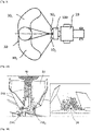
- FIG. 3 shows a top view of the tractor of [ Fig. 2 ].
- the tractor 20 transports means for distributing particles 100, for example granular fertilizers or seedlings. It is equipped with two distributors supplying two discs 10 1 and 10 2 , which ensure the projection of the particles respectively onto surfaces 30 1 and 30 2 , together defining a covering surface 30, distant from 5 to 30 m from the distribution means 100 , and defining a general crescent shape.
- the spreading device is equipped with a chute for distributing the particles to be spread, from the outlet of the dispenser, to the spreading disc.
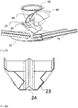
- such a chute 23 is provided with a V-shaped profile 24, which runs on the bottom wall of the chute, according to the direction of the trajectory of the flow of particles 210, from the outlet 40 of the doser, towards the lower end from the chute.
- the V profile 24 fulfills a function of splitting and widening the flow 210 at the outlet of the feeder: the flow of particles is split into two flows 210 1 and 210 2 , on either side other of the V-shaped profile 24.
- two drop points appear on the spreading disc 10, on either side of the center line of the chute 23: a bimodal distribution of the particles is therefore obtained on removal on the disk.
- the flux 210 then covers the V profile 23, so that the impact of its presence on the spot obtained on the disc is less than in the case of a low flow rate.
- the product to be spread passes over the V profile 23 to provide only one point of fall on the disc: the effect of the means of bursting and widening of the flow fades thus at higher throughput, and has little impact on the geometry of product deposit on the disc.
- the curve in dotted lines of the Fig. 5A corresponds to the same curve of angular mass distribution of the spot obtained with a chute according to the prior art, devoid of means for bursting and widening the flow 210 of particles.
- the spreading system then makes it possible to smooth this distribution, by making it tend towards a uniform profile (presence of a central plateau).
- This curve in dotted lines has a more marked peak centered around -110°, whereas the curve in solid lines, according to one embodiment of the invention, has a wide central plateau substantially between -150° and -75°.
- FIG. 7 shows a perspective view of a portion of the spreading device according to this first embodiment of the invention.
- the doser 42 has an outlet opening 40, which can be closed off by a rotary valve 41.
- the particles 21 stored in the hopper 22 flow from the dispenser, through the outlet opening 40, and fall onto the chute 23.
- the bottom wall of the chute 23 is equipped with a V-shaped profile 24, which runs along the chute, in the direction of flow of the flow of particles towards the disc 10.
- the V-shaped profile 24 is arranged plumb with the opening of outlet 40, so that the upper edge of the V is substantially centered with respect to the outlet opening 40.
- the flow of particles falls, substantially perpendicular to the horizon line, from the doser, it meets the upper edge of the V profile 24, which bursts and widens the flow on either side of the profile 24.
- the particle deposit spot on the disc 10 is then widened, and may present, low flow, bimodal distribution.
- the particles are then ejected from the disc 10 by the blades 70.
- FIG. 8A shows an embodiment of the chute 23, in which the means for bursting and widening the flow comprise a central rib, in the form of a V profile 24.
- Fig. 8B presents another embodiment of the chute 23, in which the means for bursting and widening the flow comprise a U-shaped profile 25.
- FIG. 9 shows a front view of a chute 23 fitted with a V-shaped profile 24 plumb with the outlet orifice 40 of the dispenser.
- the upper edge 241 of the V profile 24 is preferably centered with respect to the exit opening 40.
- the trough 23 can be dismantled without tools, thanks to the use of clamping screws, through the orifices 26.
- the trough 23 can be mounted by clipping.
- the chute 23 is composed of a rigid part forming a skeleton and allowing the functional dimensions to be held.
- the V profile 24 offers a stiffener to the chute allowing plastics processing without impacting the maintenance of the functional dimensions over time.
- a flexible material for example silicone or PVC, is added to the bottom of the skeleton of the chute, to facilitate cleaning in the field without dismantling.
- a flexible material for example silicone or PVC
- the two zones 271 and 272 on either side of the means for bursting and widening the flow are for example covered with flexible silicone allowing manual demolding of the crust of dust which forms during use.
- the V profile 24 is itself removable, to further facilitate cleaning in case of clogging.
- FIG. 12 presents an alternative embodiment in which the dispenser has two outlet openings 40 1 and 40 2 .
- two V-shaped profiles 24 1 and 24 2 are placed in the bottom of the chute 23, each of which is located directly above one of the outlet openings 40 1 and 40 2 of the dispenser.
- These two V-shaped (or U-shaped) profiles extend over the bottom wall of the chute 23 along the direction of displacement of the flow of particles, from the outlet opening 40 1 , 40 2 , towards the end bottom of the chute 23, where this flow falls on the spreading disc 10.
- the means for bursting and widening the flow extend into means for guiding the flow of particles.
- These guide means advantageously make it possible to orient the product to be spread at a low flow rate, and further attenuate the dose effect. In particular, they make it possible to maintain a constant mean angle of ejection at the outlet of the blade, whatever the feed rate of the chute 23.
- the V profile 24 is not straight, but follows a curved path at the lower end of the chute 23, in order to move the barycenter of the flow section 210 of particle flow.
- the central edge 241 of the V-shaped profile 24 follows a curve, making it possible to shift the spot for depositing product on the disk 10 at low flow.
- the 130 mark on the [ Fig. 13B ] illustrates this deviation of the low flow rate.
- the movement of the centroid of the section of the product flow causes the movement of the average feed point, which is angularly offset on the disc, so as to delay its setting into a blade.
- FIG. 13A illustrates, in superposition, the curves, obtained for different mass flow rates at the metering outlet, of the angular mass distributions at the blade outlet.
- the curve in dotted lines represents the evolution of the mass distribution as a function of the exit angle of the blades for a high flow rate; the curve in solid lines represents the evolution of the mass distribution as a function of the exit angle of the blades for a low flow rate.
- Fig. 14 presents another alternative embodiment of the chute 23, in which the profile has a more complex shape, the section of which, in the plane perpendicular to the bottom wall of the chute, widens in the direction of the end exit from the latter.
- Such an elaborate shape makes it possible to separate the functions of bursting and broadening of the flow, which is particularly advantageous for products with a low standard deviation, such as slug repellent.
- the profile directly above the doser outlet opening (zone referenced 26), the profile has for example a triangular section, which allows the flow of particles to be split.
- This section gradually widens in the direction of the outlet of the chute, to take a trapezoidal shape 251 at the level of the outlet end of the chute 23 (zone referenced 25): the widening of the flow is thus increased until achieve a dissociation of right and left particle flows, on either side of the profile.
- This variant can be advantageously combined with that of figure [ Fig. 13B ], so as to both increase flux broadening and shift the barycenter of the particle flow flux section.
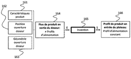
- FIG. 15 The flowchart of figure [ Fig. 15 ] summarizes the general principle of the device according to the various embodiments of the invention. As illustrated in schematic form in this figure, it aims to obtain a constant product supply profile at the input of the plate 10 (block referenced 166), whatever the product supply profile at the output of the dispenser (block referenced 164 ).
- the flow of product to be spread at the meter outlet depends on multiple parameters, such as the characteristics 161 of the product to be spread (granularity, density, etc.), the meter opening position 162 (i.e. position of the closing flap of this opening), or even the geometry 163 of this opening (i.e. the shape of the opening itself or of a flow rate selector which can be interfaced on this opening, to adapt the range feed rates to the characteristics of the product to be spread).
- the characteristics 161 of the product to be spread granularity, density, etc.
- the meter opening position 162 i.e. position of the closing flap of this opening
- the geometry 163 of this opening i.e. the shape of the opening itself or of a flow rate selector which can be interfaced on this opening, to adapt the range feed rates to the characteristics of the product to be spread.
- the invention allows a dissociation of the metering and spreading functions, unlike the techniques of the prior art.
Landscapes
- Life Sciences & Earth Sciences (AREA)
- Soil Sciences (AREA)
- Environmental Sciences (AREA)
- Filling Or Emptying Of Bunkers, Hoppers, And Tanks (AREA)
- Nozzles (AREA)
- Basic Packing Technique (AREA)
Applications Claiming Priority (1)
| Application Number | Priority Date | Filing Date | Title |
|---|---|---|---|
| FR2002956A FR3108465B1 (fr) | 2020-03-26 | 2020-03-26 | Dispositif d’épandage de particules à disques rotatifs compensant l’effet dose à faible débit |
Publications (2)
| Publication Number | Publication Date |
|---|---|
| EP3884754A1 EP3884754A1 (fr) | 2021-09-29 |
| EP3884754B1 true EP3884754B1 (fr) | 2022-11-02 |
Family
ID=70804794
Family Applications (1)
| Application Number | Title | Priority Date | Filing Date |
|---|---|---|---|
| EP21165183.1A Active EP3884754B1 (fr) | 2020-03-26 | 2021-03-26 | Dispositif d'épandage de particules à disques rotatifs compensant l'effet dose à faible débit |
Country Status (5)
| Country | Link |
|---|---|
| EP (1) | EP3884754B1 (pl) |
| DE (1) | DE202021101632U1 (pl) |
| DK (1) | DK3884754T3 (pl) |
| FR (1) | FR3108465B1 (pl) |
| PL (1) | PL3884754T3 (pl) |
Family Cites Families (9)
| Publication number | Priority date | Publication date | Assignee | Title |
|---|---|---|---|---|
| US3889883A (en) * | 1974-01-07 | 1975-06-17 | Tci | Live bottom chute for spreaders |
| FR2566991B1 (fr) | 1984-07-09 | 1987-01-16 | Burel Ets F | Machine d'epandage centrifuge de produits en grains. |
| NL8403271A (nl) | 1984-10-29 | 1986-05-16 | Lely Nv C Van Der | Inrichting voor het verspreiden van materiaal. |
| FR2669806B1 (fr) * | 1990-12-04 | 1993-03-19 | Sulky Burel Sa | Procede et dispositif pour modifier le spectre d'une machine d'epandage centrifuge de produits en grains, en vue de l'epandage en bordure de champ. |
| EP1430763A3 (de) * | 2002-12-19 | 2004-08-18 | Amazonen-Werke H. Dreyer GmbH & Co. KG | Zentrifugaldüngerstreuer |
| FR2858514B1 (fr) * | 2003-08-08 | 2005-09-30 | Sulky Burel | Procede d'epandage centrifuge d'engrais ou de produits similaires en grains |
| DE102005015236A1 (de) | 2005-04-02 | 2006-10-05 | Rauch Landmaschinenfabrik Gmbh | Zweischeibenstreuer für Streugut, insbesondere Dünger, Salz oder dergleichen |
| DE102009026344A1 (de) | 2009-08-07 | 2011-02-10 | Amazonen-Werke H. Dreyer Gmbh & Co. Kg | Zweischeibenstreuer |
| FR2967547B1 (fr) | 2010-11-18 | 2014-02-07 | Sulky Burel | Dispositif d'epandage centrifuge a goulotte permettant de prendre en compte l'effet debit |
-
2020
- 2020-03-26 FR FR2002956A patent/FR3108465B1/fr active Active
-
2021
- 2021-03-26 DK DK21165183.1T patent/DK3884754T3/da active
- 2021-03-26 EP EP21165183.1A patent/EP3884754B1/fr active Active
- 2021-03-26 DE DE202021101632.9U patent/DE202021101632U1/de active Active
- 2021-03-26 PL PL21165183.1T patent/PL3884754T3/pl unknown
Also Published As
| Publication number | Publication date |
|---|---|
| BR102021004621A2 (pt) | 2021-10-05 |
| PL3884754T3 (pl) | 2023-03-06 |
| FR3108465A1 (fr) | 2021-10-01 |
| FR3108465B1 (fr) | 2022-04-08 |
| DE202021101632U1 (de) | 2021-05-14 |
| DK3884754T3 (da) | 2023-01-30 |
| EP3884754A1 (fr) | 2021-09-29 |
Similar Documents
| Publication | Publication Date | Title |
|---|---|---|
| FR2991132A1 (fr) | Boitier de distribution pour semoir monograine avec rainures ouvertes et semoir utilisant un tel boitier | |
| FR2569939A1 (fr) | Distributeur de substances pour l'epandage a la volee | |
| EP3479670B1 (fr) | Dispositif d'ouverture pour semoir | |
| EP2454928B1 (fr) | Dispositif d'épandage à goulotte permettant de prendre en compte l'effet débit | |
| EP3884754B1 (fr) | Dispositif d'épandage de particules à disques rotatifs compensant l'effet dose à faible débit | |
| FR2691040A1 (fr) | Dispositif régulateur de distribution des graines pour semoir. | |
| FR2553251A1 (fr) | Procede et appareil pour l'epandage d'engrais | |
| EP3721692B1 (fr) | Dispositif d'épandage de particules à goulotte rotative | |
| EP1955579A1 (fr) | Machine et procédé d'épandage centrifuge d'engrais ou de produits similaires en grains. | |
| EP0820689B1 (fr) | Dispositif d'épandage centrifuge d'engrais ou de produits similaires en grains | |
| DK172504B1 (da) | Spredemaskine, specielt gødningsspredemaskine | |
| EP3138375B1 (fr) | Dispositif de dosage pour système de distribution de particules pour machine agricole, et système de distribution correspondant | |
| EP1504645A1 (fr) | Procédé d'épandage centrifuge d'engrais ou de produits similaires en grains | |
| FR2481568A1 (fr) | Dispositif doseur pour l'epandage de matieres en grains et en poudre | |
| EP0038241B1 (fr) | Procédé de mise en terre des graines pour les semis dits de précision et semoir mettant en oeuvre un tel procédé | |
| EP3692778B1 (fr) | Dispositif de dosage de particules à épandre à boisseau rotatif, et machine agricole correspondante | |
| EP1721502B1 (fr) | Dispositif d'épandage centrifuge d'un produit pulvérulent ou granulaire | |
| EP1336332A1 (fr) | Dispositif et machine d'épandage centrifuge d'engrais ou de produits similaires en grains | |
| FR2669806A1 (fr) | Procede et dispositif pour modifier le spectre d'une machine d'epandage centrifuge de produits en grains, en vue de l'epandage en bordure de champ. | |
| FR3159074A1 (fr) | Dispositif de dosage de particules à épandre à boisseau rotatif amélioré, et machine agricole correspondante | |
| JPH09135611A (ja) | 播種機 | |
| BR102021004621B1 (pt) | Dispositivo de espalhamento de partículas com discos rotativos que compensa o efeito da dose em baixa vazão | |
| FR2637448A1 (fr) | Dispositif et procede pour epandre des produits sur une surface, notamment epandeur d'engrais | |
| EP0209443B1 (fr) | Roue semeuse perfectionnée remplissant complémentairement les fonctions d'épandeur-localisateur de microgranules | |
| FR2481569A1 (en) | Tractor mounted distributor for seed - has distribution confined to arc of selected size by variable outlet aperture |
Legal Events
| Date | Code | Title | Description |
|---|---|---|---|
| PUAI | Public reference made under article 153(3) epc to a published international application that has entered the european phase |
Free format text: ORIGINAL CODE: 0009012 |
|
| STAA | Information on the status of an ep patent application or granted ep patent |
Free format text: STATUS: THE APPLICATION HAS BEEN PUBLISHED |
|
| AK | Designated contracting states |
Kind code of ref document: A1 Designated state(s): AL AT BE BG CH CY CZ DE DK EE ES FI FR GB GR HR HU IE IS IT LI LT LU LV MC MK MT NL NO PL PT RO RS SE SI SK SM TR |
|
| STAA | Information on the status of an ep patent application or granted ep patent |
Free format text: STATUS: REQUEST FOR EXAMINATION WAS MADE |
|
| 17P | Request for examination filed |
Effective date: 20211217 |
|
| RBV | Designated contracting states (corrected) |
Designated state(s): AL AT BE BG CH CY CZ DE DK EE ES FI FR GB GR HR HU IE IS IT LI LT LU LV MC MK MT NL NO PL PT RO RS SE SI SK SM TR |
|
| GRAP | Despatch of communication of intention to grant a patent |
Free format text: ORIGINAL CODE: EPIDOSNIGR1 |
|
| STAA | Information on the status of an ep patent application or granted ep patent |
Free format text: STATUS: GRANT OF PATENT IS INTENDED |
|
| RIC1 | Information provided on ipc code assigned before grant |
Ipc: A01C 17/00 20060101AFI20220412BHEP |
|
| INTG | Intention to grant announced |
Effective date: 20220504 |
|
| GRAJ | Information related to disapproval of communication of intention to grant by the applicant or resumption of examination proceedings by the epo deleted |
Free format text: ORIGINAL CODE: EPIDOSDIGR1 |
|
| STAA | Information on the status of an ep patent application or granted ep patent |
Free format text: STATUS: REQUEST FOR EXAMINATION WAS MADE |
|
| GRAP | Despatch of communication of intention to grant a patent |
Free format text: ORIGINAL CODE: EPIDOSNIGR1 |
|
| STAA | Information on the status of an ep patent application or granted ep patent |
Free format text: STATUS: GRANT OF PATENT IS INTENDED |
|
| INTC | Intention to grant announced (deleted) | ||
| INTG | Intention to grant announced |
Effective date: 20220721 |
|
| GRAS | Grant fee paid |
Free format text: ORIGINAL CODE: EPIDOSNIGR3 |
|
| GRAA | (expected) grant |
Free format text: ORIGINAL CODE: 0009210 |
|
| STAA | Information on the status of an ep patent application or granted ep patent |
Free format text: STATUS: THE PATENT HAS BEEN GRANTED |
|
| AK | Designated contracting states |
Kind code of ref document: B1 Designated state(s): AL AT BE BG CH CY CZ DE DK EE ES FI FR GB GR HR HU IE IS IT LI LT LU LV MC MK MT NL NO PL PT RO RS SE SI SK SM TR |
|
| REG | Reference to a national code |
Ref country code: GB Ref legal event code: FG4D Free format text: NOT ENGLISH |
|
| REG | Reference to a national code |
Ref country code: CH Ref legal event code: EP Ref country code: AT Ref legal event code: REF Ref document number: 1528064 Country of ref document: AT Kind code of ref document: T Effective date: 20221115 |
|
| REG | Reference to a national code |
Ref country code: DE Ref legal event code: R096 Ref document number: 602021000664 Country of ref document: DE |
|
| REG | Reference to a national code |
Ref country code: IE Ref legal event code: FG4D Free format text: LANGUAGE OF EP DOCUMENT: FRENCH |
|
| REG | Reference to a national code |
Ref country code: NL Ref legal event code: FP |
|
| REG | Reference to a national code |
Ref country code: DK Ref legal event code: T3 Effective date: 20230127 |
|
| REG | Reference to a national code |
Ref country code: LT Ref legal event code: MG9D |
|
| REG | Reference to a national code |
Ref country code: AT Ref legal event code: MK05 Ref document number: 1528064 Country of ref document: AT Kind code of ref document: T Effective date: 20221102 |
|
| PG25 | Lapsed in a contracting state [announced via postgrant information from national office to epo] |
Ref country code: SE Free format text: LAPSE BECAUSE OF FAILURE TO SUBMIT A TRANSLATION OF THE DESCRIPTION OR TO PAY THE FEE WITHIN THE PRESCRIBED TIME-LIMIT Effective date: 20221102 Ref country code: PT Free format text: LAPSE BECAUSE OF FAILURE TO SUBMIT A TRANSLATION OF THE DESCRIPTION OR TO PAY THE FEE WITHIN THE PRESCRIBED TIME-LIMIT Effective date: 20230302 Ref country code: NO Free format text: LAPSE BECAUSE OF FAILURE TO SUBMIT A TRANSLATION OF THE DESCRIPTION OR TO PAY THE FEE WITHIN THE PRESCRIBED TIME-LIMIT Effective date: 20230202 Ref country code: LT Free format text: LAPSE BECAUSE OF FAILURE TO SUBMIT A TRANSLATION OF THE DESCRIPTION OR TO PAY THE FEE WITHIN THE PRESCRIBED TIME-LIMIT Effective date: 20221102 Ref country code: FI Free format text: LAPSE BECAUSE OF FAILURE TO SUBMIT A TRANSLATION OF THE DESCRIPTION OR TO PAY THE FEE WITHIN THE PRESCRIBED TIME-LIMIT Effective date: 20221102 Ref country code: ES Free format text: LAPSE BECAUSE OF FAILURE TO SUBMIT A TRANSLATION OF THE DESCRIPTION OR TO PAY THE FEE WITHIN THE PRESCRIBED TIME-LIMIT Effective date: 20221102 Ref country code: AT Free format text: LAPSE BECAUSE OF FAILURE TO SUBMIT A TRANSLATION OF THE DESCRIPTION OR TO PAY THE FEE WITHIN THE PRESCRIBED TIME-LIMIT Effective date: 20221102 |
|
| PG25 | Lapsed in a contracting state [announced via postgrant information from national office to epo] |
Ref country code: RS Free format text: LAPSE BECAUSE OF FAILURE TO SUBMIT A TRANSLATION OF THE DESCRIPTION OR TO PAY THE FEE WITHIN THE PRESCRIBED TIME-LIMIT Effective date: 20221102 Ref country code: LV Free format text: LAPSE BECAUSE OF FAILURE TO SUBMIT A TRANSLATION OF THE DESCRIPTION OR TO PAY THE FEE WITHIN THE PRESCRIBED TIME-LIMIT Effective date: 20221102 Ref country code: IS Free format text: LAPSE BECAUSE OF FAILURE TO SUBMIT A TRANSLATION OF THE DESCRIPTION OR TO PAY THE FEE WITHIN THE PRESCRIBED TIME-LIMIT Effective date: 20230302 Ref country code: HR Free format text: LAPSE BECAUSE OF FAILURE TO SUBMIT A TRANSLATION OF THE DESCRIPTION OR TO PAY THE FEE WITHIN THE PRESCRIBED TIME-LIMIT Effective date: 20221102 Ref country code: GR Free format text: LAPSE BECAUSE OF FAILURE TO SUBMIT A TRANSLATION OF THE DESCRIPTION OR TO PAY THE FEE WITHIN THE PRESCRIBED TIME-LIMIT Effective date: 20230203 |
|
| P01 | Opt-out of the competence of the unified patent court (upc) registered |
Effective date: 20230527 |
|
| PG25 | Lapsed in a contracting state [announced via postgrant information from national office to epo] |
Ref country code: SM Free format text: LAPSE BECAUSE OF FAILURE TO SUBMIT A TRANSLATION OF THE DESCRIPTION OR TO PAY THE FEE WITHIN THE PRESCRIBED TIME-LIMIT Effective date: 20221102 Ref country code: RO Free format text: LAPSE BECAUSE OF FAILURE TO SUBMIT A TRANSLATION OF THE DESCRIPTION OR TO PAY THE FEE WITHIN THE PRESCRIBED TIME-LIMIT Effective date: 20221102 Ref country code: EE Free format text: LAPSE BECAUSE OF FAILURE TO SUBMIT A TRANSLATION OF THE DESCRIPTION OR TO PAY THE FEE WITHIN THE PRESCRIBED TIME-LIMIT Effective date: 20221102 Ref country code: CZ Free format text: LAPSE BECAUSE OF FAILURE TO SUBMIT A TRANSLATION OF THE DESCRIPTION OR TO PAY THE FEE WITHIN THE PRESCRIBED TIME-LIMIT Effective date: 20221102 |
|
| REG | Reference to a national code |
Ref country code: DE Ref legal event code: R097 Ref document number: 602021000664 Country of ref document: DE |
|
| PG25 | Lapsed in a contracting state [announced via postgrant information from national office to epo] |
Ref country code: SK Free format text: LAPSE BECAUSE OF FAILURE TO SUBMIT A TRANSLATION OF THE DESCRIPTION OR TO PAY THE FEE WITHIN THE PRESCRIBED TIME-LIMIT Effective date: 20221102 Ref country code: AL Free format text: LAPSE BECAUSE OF FAILURE TO SUBMIT A TRANSLATION OF THE DESCRIPTION OR TO PAY THE FEE WITHIN THE PRESCRIBED TIME-LIMIT Effective date: 20221102 |
|
| PLBE | No opposition filed within time limit |
Free format text: ORIGINAL CODE: 0009261 |
|
| STAA | Information on the status of an ep patent application or granted ep patent |
Free format text: STATUS: NO OPPOSITION FILED WITHIN TIME LIMIT |
|
| 26N | No opposition filed |
Effective date: 20230803 |
|
| PG25 | Lapsed in a contracting state [announced via postgrant information from national office to epo] |
Ref country code: MC Free format text: LAPSE BECAUSE OF FAILURE TO SUBMIT A TRANSLATION OF THE DESCRIPTION OR TO PAY THE FEE WITHIN THE PRESCRIBED TIME-LIMIT Effective date: 20221102 |
|
| PG25 | Lapsed in a contracting state [announced via postgrant information from national office to epo] |
Ref country code: SI Free format text: LAPSE BECAUSE OF FAILURE TO SUBMIT A TRANSLATION OF THE DESCRIPTION OR TO PAY THE FEE WITHIN THE PRESCRIBED TIME-LIMIT Effective date: 20221102 |
|
| REG | Reference to a national code |
Ref country code: BE Ref legal event code: MM Effective date: 20230331 |
|
| PG25 | Lapsed in a contracting state [announced via postgrant information from national office to epo] |
Ref country code: LU Free format text: LAPSE BECAUSE OF NON-PAYMENT OF DUE FEES Effective date: 20230326 |
|
| REG | Reference to a national code |
Ref country code: IE Ref legal event code: MM4A |
|
| PG25 | Lapsed in a contracting state [announced via postgrant information from national office to epo] |
Ref country code: IE Free format text: LAPSE BECAUSE OF NON-PAYMENT OF DUE FEES Effective date: 20230326 |
|
| PG25 | Lapsed in a contracting state [announced via postgrant information from national office to epo] |
Ref country code: BE Free format text: LAPSE BECAUSE OF NON-PAYMENT OF DUE FEES Effective date: 20230331 |
|
| PG25 | Lapsed in a contracting state [announced via postgrant information from national office to epo] |
Ref country code: IT Free format text: LAPSE BECAUSE OF FAILURE TO SUBMIT A TRANSLATION OF THE DESCRIPTION OR TO PAY THE FEE WITHIN THE PRESCRIBED TIME-LIMIT Effective date: 20221102 |
|
| REG | Reference to a national code |
Ref country code: CH Ref legal event code: PL |
|
| PG25 | Lapsed in a contracting state [announced via postgrant information from national office to epo] |
Ref country code: BG Free format text: LAPSE BECAUSE OF FAILURE TO SUBMIT A TRANSLATION OF THE DESCRIPTION OR TO PAY THE FEE WITHIN THE PRESCRIBED TIME-LIMIT Effective date: 20221102 |
|
| PG25 | Lapsed in a contracting state [announced via postgrant information from national office to epo] |
Ref country code: BG Free format text: LAPSE BECAUSE OF FAILURE TO SUBMIT A TRANSLATION OF THE DESCRIPTION OR TO PAY THE FEE WITHIN THE PRESCRIBED TIME-LIMIT Effective date: 20221102 |
|
| PG25 | Lapsed in a contracting state [announced via postgrant information from national office to epo] |
Ref country code: CH Free format text: LAPSE BECAUSE OF NON-PAYMENT OF DUE FEES Effective date: 20240331 |
|
| PG25 | Lapsed in a contracting state [announced via postgrant information from national office to epo] |
Ref country code: CY Free format text: LAPSE BECAUSE OF FAILURE TO SUBMIT A TRANSLATION OF THE DESCRIPTION OR TO PAY THE FEE WITHIN THE PRESCRIBED TIME-LIMIT; INVALID AB INITIO Effective date: 20210326 |
|
| PG25 | Lapsed in a contracting state [announced via postgrant information from national office to epo] |
Ref country code: HU Free format text: LAPSE BECAUSE OF FAILURE TO SUBMIT A TRANSLATION OF THE DESCRIPTION OR TO PAY THE FEE WITHIN THE PRESCRIBED TIME-LIMIT; INVALID AB INITIO Effective date: 20210326 |
|
| GBPC | Gb: european patent ceased through non-payment of renewal fee |
Effective date: 20250326 |
|
| PG25 | Lapsed in a contracting state [announced via postgrant information from national office to epo] |
Ref country code: TR Free format text: LAPSE BECAUSE OF FAILURE TO SUBMIT A TRANSLATION OF THE DESCRIPTION OR TO PAY THE FEE WITHIN THE PRESCRIBED TIME-LIMIT Effective date: 20221102 |
|
| PG25 | Lapsed in a contracting state [announced via postgrant information from national office to epo] |
Ref country code: GB Free format text: LAPSE BECAUSE OF NON-PAYMENT OF DUE FEES Effective date: 20250326 |
|
| PGFP | Annual fee paid to national office [announced via postgrant information from national office to epo] |
Ref country code: NL Payment date: 20260226 Year of fee payment: 6 |
|
| PGFP | Annual fee paid to national office [announced via postgrant information from national office to epo] |
Ref country code: DK Payment date: 20260226 Year of fee payment: 6 Ref country code: DE Payment date: 20260313 Year of fee payment: 6 |
|
| PGFP | Annual fee paid to national office [announced via postgrant information from national office to epo] |
Ref country code: FR Payment date: 20260330 Year of fee payment: 6 |
|
| PGFP | Annual fee paid to national office [announced via postgrant information from national office to epo] |
Ref country code: PL Payment date: 20260227 Year of fee payment: 6 |