EP3884197B1 - Kopplung - Google Patents
Kopplung Download PDFInfo
- Publication number
- EP3884197B1 EP3884197B1 EP19808744.7A EP19808744A EP3884197B1 EP 3884197 B1 EP3884197 B1 EP 3884197B1 EP 19808744 A EP19808744 A EP 19808744A EP 3884197 B1 EP3884197 B1 EP 3884197B1
- Authority
- EP
- European Patent Office
- Prior art keywords
- receiving
- securing
- securing element
- coupling
- retaining
- Prior art date
- Legal status (The legal status is an assumption and is not a legal conclusion. Google has not performed a legal analysis and makes no representation as to the accuracy of the status listed.)
- Active
Links
Images



Classifications
-
- F—MECHANICAL ENGINEERING; LIGHTING; HEATING; WEAPONS; BLASTING
- F16—ENGINEERING ELEMENTS AND UNITS; GENERAL MEASURES FOR PRODUCING AND MAINTAINING EFFECTIVE FUNCTIONING OF MACHINES OR INSTALLATIONS; THERMAL INSULATION IN GENERAL
- F16L—PIPES; JOINTS OR FITTINGS FOR PIPES; SUPPORTS FOR PIPES, CABLES OR PROTECTIVE TUBING; MEANS FOR THERMAL INSULATION IN GENERAL
- F16L37/00—Couplings of the quick-acting type
- F16L37/08—Couplings of the quick-acting type in which the connection between abutting or axially overlapping ends is maintained by locking members
- F16L37/084—Couplings of the quick-acting type in which the connection between abutting or axially overlapping ends is maintained by locking members combined with automatic locking
- F16L37/0841—Couplings of the quick-acting type in which the connection between abutting or axially overlapping ends is maintained by locking members combined with automatic locking by means of a transversally slidable locking member surrounding the tube
-
- F—MECHANICAL ENGINEERING; LIGHTING; HEATING; WEAPONS; BLASTING
- F16—ENGINEERING ELEMENTS AND UNITS; GENERAL MEASURES FOR PRODUCING AND MAINTAINING EFFECTIVE FUNCTIONING OF MACHINES OR INSTALLATIONS; THERMAL INSULATION IN GENERAL
- F16L—PIPES; JOINTS OR FITTINGS FOR PIPES; SUPPORTS FOR PIPES, CABLES OR PROTECTIVE TUBING; MEANS FOR THERMAL INSULATION IN GENERAL
- F16L37/00—Couplings of the quick-acting type
- F16L37/02—Couplings of the quick-acting type in which the connection is maintained only by friction of the parts being joined
-
- F—MECHANICAL ENGINEERING; LIGHTING; HEATING; WEAPONS; BLASTING
- F16—ENGINEERING ELEMENTS AND UNITS; GENERAL MEASURES FOR PRODUCING AND MAINTAINING EFFECTIVE FUNCTIONING OF MACHINES OR INSTALLATIONS; THERMAL INSULATION IN GENERAL
- F16L—PIPES; JOINTS OR FITTINGS FOR PIPES; SUPPORTS FOR PIPES, CABLES OR PROTECTIVE TUBING; MEANS FOR THERMAL INSULATION IN GENERAL
- F16L37/00—Couplings of the quick-acting type
- F16L37/08—Couplings of the quick-acting type in which the connection between abutting or axially overlapping ends is maintained by locking members
- F16L37/12—Couplings of the quick-acting type in which the connection between abutting or axially overlapping ends is maintained by locking members using hooks, pawls, or other movable or insertable locking members
- F16L37/14—Joints secured by inserting between mating surfaces an element, e.g. a piece of wire, a pin, a chain
- F16L37/142—Joints secured by inserting between mating surfaces an element, e.g. a piece of wire, a pin, a chain where the securing element is inserted tangentially
- F16L37/144—Joints secured by inserting between mating surfaces an element, e.g. a piece of wire, a pin, a chain where the securing element is inserted tangentially the securing element being U-shaped
Definitions
- the present invention relates to a coupling which is used, for example, to connect fluid lines in order to securely fasten these fluid lines to one another.
- the present invention is therefore based on the object of providing a coupling which provides a reliable and secure connection, for example, of two fluid lines.
- the position of the securing element in the coupling according to the invention clearly indicates whether a fluid line connected to the male element is correctly connected to a fluid line connected to the female element.
- the term "separately formed retaining element” refers to a separate design of the retaining element and the securing element, at least in the locking position of the securing element on the receiving element. It is entirely conceivable that the at least one retaining element and the securing element could initially be connected in one piece and separated when the insert element is first inserted, for example, by releasing a predetermined breaking point.
- the insertion axis may, for example, coincide with a longitudinal center axis of the receiving space and/or with a longitudinal center axis of the plug-in element.
- the plug-in element can be configured to displace the at least one retaining element radially outward, at least in sections, upon insertion of the plug-in element into the receiving space of the receiving element. In this way, only the insertion force of the plug-in element into the receiving space of the receiving element increases in order to displace a respective section of a retaining element, without requiring any other actions to displace the respective section of a retaining element.
- the displacement axis of the securing element can be substantially perpendicular to the insertion axis of the male element. This can result in the advantage that a rotationally symmetrical male element can be inserted into the female element in any rotational orientation and still engage with the securing element in a defined manner.
- the securing element can be configured to be transferable from a state separated from the receiving element into the release position of the receiving element provided with the at least one holding element, wherein the securing element can further be configured to displace the at least one holding element via an insertion bevel provided on the securing element.
- a securing element manufactured separately from the receiving element can interact with the receiving element and the at least one holding element during preparation for coupling or assembly of the receiving element with the securing element and the at least one holding element in such a way that the securing element can be brought into the release position on the receiving element without the use of tools.
- the insertion bevel on the securing element can displace the at least one holding element, for example in the form of a snap connection radially outwards, in order to achieve the release position.
- the assembly of the receiving element with the securing element and the at least one holding element can only be made possible if no plug-in element is inserted into the receiving element.
- two holding elements can be provided, in particular diametrically opposite with respect to a longitudinal central axis of the receiving element, which are advantageously attached to a are arranged on a common support element.
- This allows the interaction of the securing element and the holding element to be reinforced, so that a displacement of the securing element from the release position to the locking position in the event of an incorrectly connected coupling can be secured even against high forces acting on the securing element, which could, for example, overcome the interaction of the securing element with only one holding element.
- the at least one retaining element can be connected to the receiving element parallel to the insertion axis.
- the at least one retaining element can be inserted into a recess, such as a slot, in the receiving element and can be connected there to the receiving element in a non-detachable manner, i.e., in a manner that cannot be removed without causing damage.
- the securing element can be designed as a closed ring whose through-hole extends in a direction parallel to the insertion axis when the securing element is in the release or locking position.
- the securing element cannot be displaced from the locking position beyond the release position, since the securing element at least partially surrounds the insertion element and abuts against it.
- the term “ring” here does not necessarily mean “circular,” but merely that a structure is closed around a through-hole.
- the term “ring” is also intended to encompass polygonal, such as rectangular, enclosed through-holes.
- a free space can be formed between a section of the securing element and a section of the receiving element which is adjacent thereto in a direction parallel to the insertion axis and which is suitable for inserting a tool in order to thereby displace the securing element from the locking position towards the release position, wherein the section of the securing element which is adjacent to the free space has, in particular, a recess facing the free space, which recess is designed to receive the tool.
- a screwdriver can be inserted into the free space and the securing element can be levered radially outwards with respect to the receiving element while being supported on the receiving element.
- a projection can be provided on the securing element, under which the tool can engage.
- the projection can be arranged in particular at a radially outer end of the securing element.
- the projection can be designed in cooperation with the free space such that the securing element can be displaced out of the locking position by rotating the tool.
- the section of the receiving element adjacent to the free space can extend inclined to the insertion axis, so that a tool which is placed at an upper end of the slope formed thereby and is displaced towards the securing element along the slope can reach the securing element in a targeted manner under the projection.
- the securing element can have a recess arranged radially on the outside of the securing element for each retaining element, which recess can be configured to engage with a respective retaining element in the release position of the securing element in such a way that displacement of the securing element along the displacement axis of the securing element in both directions is substantially prevented.
- substantially here means that a slight play, which cannot be avoided due to manufacturing technology, can be permitted.
- each retaining element has a projection that extends radially inward when connected to the receiving element.
- the projection can come into contact with the male element and be forced radially outward by the male element to release the securing element.
- a section of the projection extending radially inward the furthest extends radially further inward than a section of an inner wall of the receiving space into which the projection extends that extends radially inward, but is arranged radially further outward than a section of an inner wall of the through-hole of the securing element that extends radially inward the furthest, through which the plug-in element is guided when connecting the plug-in element to the receiving element. Therefore, the projection can only come into contact with a predetermined section of the plug-in element and can be displaced in a defined manner.
- this can facilitate the insertion of the plug-in element because, until the projection comes into contact with the section of the plug-in element provided for this purpose, there is no contact between the holding element and the plug-in element, which could make insertion of the plug-in element into the receiving space more difficult.
- the male element can have a section on its outer circumference in which the outer diameter of the male element changes, wherein the securing element further comprises a securing section which is designed to engage with the section with changed outer diameter of the male element in the locking position of the securing element in order to prevent an axial displacement of the male element at least in one direction, preferably a release direction of the male element and the receiving element, along the insertion axis.
- This engagement of the securing element with The male element secures the male element in a predefined position relative to the female element.
- a ring on both sides of the outer circumference of the male element is also conceivable in order to secure the male element in both axial directions, i.e., in a direction of further insertion into the receiving space of the female element and in a direction of release of the male element from the female element.
- each retaining element comprises an arm extending parallel to the insertion axis and resilient in a radial direction relative to the insertion axis.
- the coupling can comprise a locking device acting between the receiving element and the securing element.
- the locking device has, for example, two locking positions, which correspond to the locking position and the release position of the securing element on the receiving element. Correct locking of this locking device provides a further means of checking the correct positioning of the securing element on the receiving element. Furthermore, this can further prevent an unintentional displacement of the securing element from the locking position to the release position.
- the locking device can comprise a leaf spring, for example, designed as a separate component from the receiving element or as a section integral with the receiving element and made of metal or plastic, which can be arranged, for example, on an outer side of the receiving element.
- the leaf spring can be connected to a section predetermined on the securing element, for example a Recess, in order to prevent displacement of the securing element from the locking position.
- it may be necessary to displace the leaf spring out of engagement with the securing element for example by pressing on a section of the leaf spring that is separate from the engagement section described above with a finger, for example.
- the leaf spring has to be displaced in a similar way in order to achieve the locking position of the securing element on the receiving element.
- a receiving section of the receiving element for the leaf spring can be designed in such a way that unwanted actuation of the leaf spring is prevented or at least significantly reduced. This can be achieved, for example, by providing projections that at least partially surround the receiving section for the leaf spring.
- the receiving space of the receiving element can be divided into a first receiving space and a second receiving space, wherein the securing element, in its locked position and its release position, viewed in a direction along the insertion axis, is arranged between the first and second receiving spaces.
- the first receiving space can be the receiving space into which the plug-in element is first inserted.
- the first receiving space can have a larger diameter of an inner wall than the second receiving space, wherein the projection of the at least one holding element can extend into the first receiving space.
- a ring of the plug-in element can, for example, only fit into the first receiving space, but not into the second receiving space.
- a longitudinal center axis of the first receiving space can advantageously be coaxial with a longitudinal center axis of the second receiving space.
- a smallest radial distance of a section of the securing element in its release position can lead to an extended
- the longitudinal center axis of the second receiving space must be greater than or equal to a smallest radial distance of a section of an inner wall of the second receiving space from the longitudinal center axis of the second receiving space, but the smallest radial distance of a section of the securing element in its release position from an extended longitudinal center axis of the first receiving space must be less than or equal to a smallest radial distance of a section of an inner wall of the first receiving space from the longitudinal center axis of the first receiving space.
- the plug-in element can thus fit through the securing element into the second receiving space with a front, radially smaller section, but abut against the securing element with a radially larger section, e.g. a ring on the outer circumference, which fits into the first receiving space.
- the plug-in element can thus assume a predefined position in which it cannot be displaced further into the receiving space of the receiving element, so that the securing element can reliably engage with the plug-in element and secure it axially.
- a coupling according to the invention is generally designated by the reference numeral 10.
- the coupling 10 comprises a receiving element 12, a securing element 14, a holding element 16 and a plug-in element 18 (see Figure 3a ).
- the receiving element 12 has at its Figure 1 At its end shown on the right, the receiving element 12 has a flange 20 which is designed to be connected to a fluid line. At its end opposite the flange 20, the receiving element 12 has a receiving space 22 into which the plug-in element 18 can be inserted (see Figures 2a and 3a ).
- the retaining element 16 is designed here as a ring on which two radially resilient retaining arms 24 are arranged diametrically opposite one another. Each of the retaining arms 24 has a radially inwardly extending projection 26. The retaining arms 24 are received in the receiving element 12 in recesses 28 provided for this purpose. In the case of the ring-shaped retaining element 16, with the retaining element 16 connected to the receiving element 12, the receiving space 22 can also be considered to be defined by the through-opening of the retaining element 16.
- the holding element 16 as well as two O-rings 30 and two spacers 32 are connected to the receiving element 12 along an insertion axis X, which here also forms a longitudinal center axis X of the receiving element 12 or of the receiving space 22.
- the securing element 14 is in Figure 1 in a position released from the receiving element 12 and can be inserted into the receiving element 12 along a displacement axis Y.
- the displacement axis Y is orthogonal to the insertion axis X.
- the securing element 14 has a through hole 34 into which the plug-in element 18 can be inserted and which is here completely enclosed by the securing element 14.
- the securing element 14 has two recesses 36 on its outer side, which are designed to engage with the holding arms 24 in a release position P1 (see Figure 2b ) to intervene.
- a leaf spring 38 is arranged on the receiving element 12, which has an end section 40 which is designed to engage with a recess 42 of the securing element 14 in order to prevent displacement of the securing element 14 relative to the Receiving element 12 in a locking position P2 (see Figure 3b ).
- the leaf spring 38 further comprises an actuating portion 44, which is designed here as at least one bend of the leaf spring such that a displacement of the actuating portion 44 towards the receiving element 12 causes a displacement of the end portion 40 of the leaf spring 38 out of the recess 42 of the securing element 14.
- Figure 2a is a side cross-sectional view of the Figure 1 illustrated embodiments of a coupling 10 according to the invention in the assembled state, with the exception of the plug-in element 18. It can be seen that the resilient retaining arms 24 are in engagement with the recesses 36, whereby a displacement of the securing element 14 from the Figure 2b shown release position P1 relative to the receiving element 12 is prevented.
- Figure 3a shows a Figure 2a Analogous sectional view, wherein the plug-in element 18 is inserted into the receiving space 22 of the receiving element 12.
- An annularly projecting portion 46 of the plug-in element 18 has come into contact with the projections 26 of the resilient retaining arms 24 of the retaining element 16 and has displaced the resilient retaining arms 24 radially outward.
- the annular projection 46 of the plug-in element 18 is located in a first receiving space 22a, whereas a front end portion of the plug-in element 18 is inserted through the securing element 14 into a second receiving space 22b, which has a smaller inner diameter d2 than an inner diameter d1 of the first receiving space 22a, so that the plug-in element 18 can be inserted into the receiving space 22 until the annular projection 46 abuts the securing element 14.
- the first receiving space 22a has a smallest radial distance r1 from the longitudinal center axis X
- the second receiving space 22b has a smallest radial distance r2 from the longitudinal center axis X
- the wall surrounding the through hole 34 of the securing element 14 has a smallest radial distance r3 from the longitudinal center axis X.
- the projections 26 protrude in the undisplaced state, ie without an inserted plug-in element, up to a radial distance r4 from the longitudinal center axis X into the first receiving space 22a.
- the spring-loaded holding arms 24 are in Figure 3a disengaged from the recesses 36 of the securing element 14, so that a displacement of the securing element 14 from the release position P1 according to Figure 2b into a locking position P2 according to Figure 3b can be carried out.
- FIG 4 is a sectional view showing in detail the interaction of the leaf spring 38 with the receiving element 12 and the securing element 14. It can be seen that a displacement of the actuating section 44 of the leaf spring 38 towards the receiving element 12 results in a displacement of the end of the leaf spring 38 opposite the end section 40 of the leaf spring 38, in the illustration according to Figure 4 to the right, causing a rotation of the end portion 40 of the leaf spring 38 in and along a receiving portion 52 of the receiving element 12, in which the Leaf spring 38 is mounted, so that the end section 40 is displaced out of the recess 42 of the securing element 14.
- FIG. 5 A further embodiment 110 of a coupling according to the invention is now shown, wherein the following will primarily focus on the differences between the embodiment 110 and the coupling 10 described above. For this reason, in the description of the coupling 110, components similar to the coupling 10 are designated by the same reference numerals, but increased by the number 100. Where applicable, all features, effects, and advantages described with reference to the coupling 10 can also be applied to the coupling 110, and vice versa.
- the coupling 110 comprises a receiving element 112, a securing element 114, a holding element 116 and an insert element 118.
- the securing element 114 is connected to the receiving element 112 via a locking mechanism 138 in its state connected to the receiving element 112, i.e. the release position P1 or the locking position P2.
- the securing element 114 can have at least one pair (or as in the Figure 5 illustrated embodiment, two pairs) of recesses 156.
- the recesses 156 are designed to engage with a spring-mounted locking projection 158, which is arranged on the receiving element 112.
- the recesses 156 Figure 5 The recesses 156 arranged below of the pair of recesses 156 are assigned to the release position P1 of the securing element 114 on the receiving element 112, and the recesses 156 arranged above them are assigned to the locking position P2.
- the securing element 114 can be formed here in a substantially U-shaped manner in two sectional planes arranged perpendicular to one another, so that the securing element 114 can be engaged with the receiving element 112 only in a single orientation relative to the latter.
- the holding element 116 is in the Figure 5 illustrated embodiment is formed integrally with an annular spacer 132, which is designed to hold a sealing element 130 (see Figures 6 and 7 ) in a predetermined position after its insertion into the receiving element 112.
- the spacer 132 is connected via webs to an annular portion 160 of the holding element 116, the inner diameter of which is larger than the inner diameter of the spacer 132.
- the annular portion 160 of the holding element 116 is provided with at least one holding arm 124 (in the illustrated embodiment, a second holding arm 124 is diametrically opposite the illustrated holding arm 124 (see Figure 7 )) such that a projection 126 arranged on the holding arm 124 is resiliently mounted relative to the annular portion 160 of the holding element 116.
- the holding arms 124 engage in recesses 128 provided on the receiving element 112. This can prevent rotation of the holding element 116 relative to the receiving element 112.
- a locking lug 162 of the holding element 116 can engage with a corresponding recess formed on the receiving element 112. to prevent displacement of the holding element 116 along the insertion axis X against the insertion direction into the receiving element 112.
- the holding element 116 here further comprises a projection 164 extending from the annular section 160 in the direction of the spacer 132 of the holding element 116, which projection engages in a recess 166 of the securing element 114 when the holding element 116 is connected to the receiving element 112, whereby a displacement of the securing element 114 from the release position P1 to the radially outward direction, i.e. a release of the securing element 114 from the receiving element 112 beyond the release position P1, can be prevented.
- two pins 168 are arranged on the securing element 114, which are designed to bear against the holding arms 124 of the holding element 116 in response to a force which urges the securing element 114 from the release position P1 towards the locking position P2 without the plug-in element 118 being correctly inserted, in order to be able to prevent the securing element 114 from reaching the locking position P2 before the plug-in element 118 has been correctly inserted.
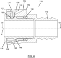
- the plug-in element 118 is now Figures 6 and 7 inserted into the receiving element 112 up to a stop, which can be formed, for example, by the interaction of an annularly projecting portion 146 of the plug-in element 118 with a portion of the holding element 116, in particular the portion of the holding element 116 forming the spacer 132, and/or with the holding arms 124, in particular by displacing them into contact with the receiving element 112 (see Figure 7 ).
- the retaining arms 124 are displaced radially outwards by the annular projection 146 of the insertion element 118 in such a way that the pins 168 of the securing element 114 can be displaced past the retaining arms 124, i.e. that the securing element 114 from the release position P1 to the locking position P2, as shown in Figure 6 is shown.
- a securing portion 150 of the securing element 114 engages behind the annular projection 146 of the plug-in element 118 in order to be able to prevent a displacement of the plug-in element 118 along the insertion axis X against the insertion direction of the plug-in element 118 into the receiving element 112.
- a free space 172 is formed between the securing element 114 and a section 170 of the receiving element 112.
- the free space 172 is designed to allow insertion of a tool, such as a screwdriver, in order to enable displacement of the securing element 114 from the locking position P2 towards the release position P1.
- the tool can be supported on the section 170 of the receiving element 112 in order to hold the securing element 114 in the Figure 6 shown view, for example, by rotating the tool.
- the section 170 of the receiving element 112 is formed with a bevel 174 along which the tool can slide.
- the securing element 114 is provided with a projection 176 facing the free space 172.
Landscapes
- Engineering & Computer Science (AREA)
- General Engineering & Computer Science (AREA)
- Mechanical Engineering (AREA)
- Quick-Acting Or Multi-Walled Pipe Joints (AREA)
- Snaps, Bayonet Connections, Set Pins, And Snap Rings (AREA)
Description
- Die vorliegende Erfindung betrifft eine Kopplung, welche beispielsweise zur Verbindung von Fluidleitungen verwendet wird, um diese Fluidleitungen sicher aneinander zu befestigen.
- Werden zwei Fluidleitungen derart miteinander verbunden, dass Fluid von der einen Leitung in die andere Leitung überführt wird, ist es üblich, ein Ende der einen Leitung in ein Ende der anderen Leitung einzuführen. Dabei kommt es immer wieder vor, dass, beispielsweise aufgrund von Reibungseffekten an Dichtungselementen, die beiden zusammengesteckten Enden der Fluidleitungen den Anschein erwecken, korrekt verbunden zu sein, es jedoch nicht sind und sich so im Einsatz voneinander lösen können.
- Dokument
US 2012/211977 A1 , welches als nächstliegender Stand der Technik erachtet wird, offenbart eine Kopplung, bei welcher ein Einsteckelement derart über ein Sicherungselement in einem Aufnahmeelement gesichert werden kann, dass erst auf ein Einführen des Einsteckelements in das Aufnahmeelement eine Verlagerung des Sicherungselements aus einer Freigabestellung in eine Verriegelungsstellung ermöglicht wird. Ferner sei auf die DokumenteEP 3 077 718 A1 , -
- Der vorliegenden Erfindung liegt daher die Aufgabe zu Grunde, eine Kopplung bereitzustellen, welche eine zuverlässige und sichere Verbindung beispielsweise zweier Fluidleitungen bereitstellt.
- Diese Aufgabe wird durch eine Kopplung nach Anspruch 1 gelöst.
- Somit kann an der erfindungsgemäßen Kopplung anhand der Stellung des Sicherungselements klar erkannt werden, ob eine mit dem Einsteckelement verbundene Fluidleitung mit einer mit dem Aufnahmeelement verbundenen Fluidleitung korrekt verbunden ist. Durch das Verhindern einer Verlagerung des Sicherungselements aus der Freigabestellung in die Verriegelungsstellung, ohne dass sich das Einsteckelement an einer vordefinierten Position befindet, kann verhindert werden, dass die Kopplung den Anschein einer korrekten Verbindung erweckt, aber dennoch nicht korrekt verbunden ist.
- Es sei an dieser Stelle erwähnt, dass unter dem Begriff "getrennt ausgebildetes Halteelement" eine getrennte Ausbildung von Halteelement und Sicherungselement in wenigstens der Verriegelungsstellung des Sicherungselements an dem Aufnahmeelement zu verstehen ist. Es ist nämlich durchaus denkbar, dass das wenigstens eine Halteelement und das Sicherungselement anfangs auch einstückig verbunden sein können und beim ersten Einstecken des Einsteckelements, zum Beispiel durch Lösen einer Sollbruchstelle, getrennt werden.
- Die Einführachse kann beispielsweise mit einer Längsmittelachse des Aufnahmeraums und/oder mit einer Längsmittelachse des Einsteckelements zusammenfallend sein.
- In einer Ausführungsform der erfindungsgemäßen Kopplung kann das Einsteckelement dazu eingerichtet sein, beim Einführen des Einsteckelements in den Aufnahmeraum des Aufnahmeelements, das wenigstens eine Halteelement zumindest abschnittsweise nach radial außen zu verlagern. Auf diese Weise erhöht sich lediglich die Einschubkraft des Einsteckelements in den Aufnahmeraum des Aufnahmeelements, um einen jeweiligen Abschnitt eines Halteelements zu verlagern, ohne dass hiervon abweichende Handlungen zur Verlagerung des jeweiligen Abschnitts eines Halteelements notwendig wären.
- Die Verlagerungsachse des Sicherungselements kann im Wesentlichen rechtwinklig zu der Einführachse des Einsteckelements sein. Daraus kann sich der Vorteile ergeben, dass ein rotatorisch symmetrisch ausgebildetes Einsteckelement in einer beliebigen rotatorischen Ausrichtung in das Aufnahmeelement eingeführt werden kann und dennoch in einer definierten Weise mit dem Sicherungselement in Eingriff treten kann.
- In einer Weiterbildung der vorliegenden Erfindung kann das Sicherungselement dazu eingerichtet sein, aus einem von dem Aufnahmeelement getrennten Zustand in das mit dem wenigstens einen Halteelement versehenen Aufnahmeelement in die Freigabestellung überführbar zu sein, wobei das Sicherungselement dabei ferner dazu eingerichtet sein kann, das wenigstens eine Halteelement über eine an dem Sicherungselement vorgesehene Einführschräge zu verlagern. Das heißt ein von dem Aufnahmeelement getrennt hergestelltes Sicherungselement kann bei einer Vorbereitung der Kopplung bzw. einem Zusammenbau des Aufnahmeelements mit dem Sicherungselement und dem wenigstens einen Halteelement derart mit dem Aufnahmeelement und dem wenigstens einen Halteelement zusammenwirken, dass das Sicherungselement ohne Verwendung von Werkzeugen in die Freigabestellung an dem Aufnahmeelement gebracht werden kann. Dabei kann die Einführschräge am Sicherungselement das wenigstens eine Halteelement, zum Beispiel im Sinne einer Schnappverbindung nach radial außen, verlagern, um die Freigabestellung zu erreichen. Insbesondere kann der Zusammenbau des Aufnahmeelements mit dem Sicherungselement und dem wenigstens einen Halteelement nur dann ermöglicht sein, wenn kein Einsteckelement in das Aufnahmeelement eingeführt ist.
- Vorteilhafterweise können zwei, insbesondere in Bezug auf eine Längsmittelachse des Aufnahmeelements diametral gegenüberliegende, Halteelemente bereitgestellt sein, welche vorteilhafterweise an einem gemeinsamen Trägerelement angeordnet sind. Hierdurch kann das Zusammenwirken von Sicherungselement und Halteelement verstärkt werden, so dass eine Verlagerung des Sicherungselements aus der Freigabestellung in die Verriegelungsstellung bei nicht korrekt verbundener Kopplung auch gegen hohe Kräfte, welche auf das Sicherungselement einwirken und beispielsweise das Zusammenwirken des Sicherungselements mit lediglich einem Halteelement überwinden könnten, gesichert werden kann.
- Insbesondere kann das wenigstens eine Halteelement parallel zu der Einführachse mit dem Aufnahmeelement verbindbar sein. Zum Beispiel kann das wenigstens eine Halteelement in eine Ausnehmung, wie beispielsweise einen Schlitz, des Aufnahmeelements einführbar sein und dort mit dem Aufnahmeelement unlösbar, das heißt nicht zerstörungsfrei lösbar, verbindbar sein.
- Das Sicherungselement kann als ein geschlossener Ring ausgebildet sein, dessen Durchgangsloch sich in einer zu der Einführachse parallelen Richtung erstreckt, wenn sich das Sicherungselement in der Freigabe- oder der Verriegelungsstellung befindet. So kann bei eingestecktem Einführelement in das Aufnahmeelement das Sicherungselement nicht aus der Verriegelungsstellung über die Freigabestellung hinaus verlagert werden, da das Sicherungselement das Einsteckelement zumindest teilweise umgibt und an diesem anschlägt. Es sei ferner erwähnt, dass der Begriff "Ring" hier nicht "kreisringförmig" bedeuten muss, sondern lediglich, dass eine um ein Durchgangsloch geschlossene Struktur vorliegt. Somit soll der Begriff "Ring" auch polygon, wie beispielsweise rechteckig, umschlossene Durchgangslöcher umfassen.
- In einem Zustand, in welchem das Sicherungselement an dem Aufnahmeelement, insbesondere in der Verriegelungsstellung, angeordnet ist, kann ein Freiraum zwischen einem Abschnitt des Sicherungselements und einem dazu in einer Richtung parallel zu der Einführachse benachbarten Abschnitt des Aufnahmeelements angeordnet sein, welcher zum Einführen eines Werkzeugs geeignet ist, um damit das Sicherungselement aus der Verriegelungsstellung in Richtung der Freigabestellung zu verlagern, wobei der an den Freiraum angrenzende Abschnitt des Sicherungselements insbesondere eine zu dem Freiraum weisende Ausnehmung ausweist, welche dazu eingerichtet ist, das Werkzeug aufzunehmen. So kann beispielsweise in den Freiraum ein Schraubendreher eingeführt werden und das Sicherungselement unter Abstützung an dem Aufnahmeelement in Bezug auf das Aufnahmeelement nach radial außen gehebelt werden. Alternativ oder zusätzlich zu der Ausnehmung kann an dem Sicherungselement ein Vorsprung vorgesehen sein, unter welchen das Werkzeug eingreifen kann. So kann der Vorsprung insbesondere an einem radial äußeren Ende des Sicherungselements angeordnet sein. Dabei kann der Vorsprung so in Zusammenwirkung mit dem Freiraum ausgebildet sein, dass das Sicherungselement durch Drehen des Werkzeugs aus der Verriegelungsstellung herausverlagert werden kann. Vorteilhafterweise kann der an den Freiraum angrenzende Abschnitt des Aufnahmeelements dabei zu der Einführachse geneigt verlaufen, so dass ein Werkzeug, welches an einem oberen Ende der dadurch gebildeten Schräge angesetzt wird und zu dem Sicherungselement entlang der Schräge verlagert wird, das Sicherungselement gezielt unter dem Vorsprung erreichen kann.
- Ferner kann das Sicherungselement für jedes Halteelement eine radial außen am Sicherungselement angeordnete Ausnehmung aufweisen, welche dazu eingerichtet sein kann, in der Freigabestellung des Sicherungselements, mit einem jeweiligen Halteelement derart in Eingriff zu stehen, dass eine Verlagerung des Sicherungselements entlang der Verlagerungsachse des Sicherungselements in beide Richtungen im Wesentlichen verhindert wird. Wobei "im Wesentlichen" hier bedeutet, dass ein leichtes Spiel, welches herstellungstechnisch nicht zu vermeiden ist, zugelassen sein kann.
- Erfindungsgemäß weist jedes Halteelement einen im mit dem Aufnahmeelement verbundenen Zustand sich nach radial innen ersteckenden Vorsprung auf. Der Vorsprung kann mit dem Einsteckelement in Kontakt treten und von diesem nach radial außen gedrängt werden, um das Sicherungselement freizugeben.
- Dabei erstreckt sich ein am weitesten nach radial innen erstreckender Abschnitt des Vorsprungs radial weiter nach innen als ein sich am weitesten nach radial innen erstreckender Abschnitt einer Innenwandung des Aufnahmeraums, in welchen sich der Vorsprung hinein erstreckt, aber ist radial weiter außen angeordnet als ein sich am weitesten nach radial innen erstreckender Abschnitt einer Innenwandung des Durchgangslochs des Sicherungselements, durch welches hindurch das Einsteckelement beim Verbinden des Einsteckelements mit dem Aufnahmeelement geführt wird. Daher kann der Vorsprung nur mit einem vorbestimmten Abschnitt des Einsteckelements in Kontakt treten und auf eine definierte Weise verlagert werden. Ferner kann dadurch das Einführen des Einsteckelements erleichtert werden, da bis zum Kontaktieren des Vorsprungs mit dem dafür vorgesehenen Abschnitt des Einsteckelements kein Kontakt zwischen Halteelement und Einsteckelement, welcher ein Einführen des Einsteckelements in den Aufnahmeraum erschweren könnte, besteht.
- Das Einsteckelement kann an seinem Außenumfang einen Abschnitt aufweisen, in welchem sich der Außendurchmesser des Einsteckelements ändert, wobei das Sicherungselement ferner einen Sicherungsabschnitt umfasst, welcher dazu eingerichtet ist, in der Verriegelungsstellung des Sicherungselements mit dem Abschnitt mit geändertem Außendurchmesser des Einsteckelements einzugreifen, um eine axiale Verlagerung des Einsteckelements zumindest in einer Richtung, vorzugsweise einer Löserichtung von Einsteckelement und Aufnahmeelement, entlang der Einführachse zu verhindern. Dieses Eingreifen des Sicherungselements mit dem Einsteckelement sichert das Einsteckelement an einer vordefinierten Position relativ zu dem Aufnahmeelement. Auch ein beidseitiges Umgreifen eines Rings am Außenumfang des Einsteckelements ist denkbar, um eine Sicherung des Einsteckelements in beide Achsrichtungen, das heißt in eine Richtung eines weiteren Einführens in den Aufnahmeraum des Aufnahmeelements und in eine Richtung eines Lösens des Einsteckelements von dem Aufnahmeelement, bereitzustellen.
- Jedes Halteelement umfasst erfindungsgemäß einen sich parallel zu der Einführachse erstreckenden und in einer radialen Richtung in Bezug auf die Einführachse federnden Arm. Somit ist auf einfache Weise eine Verlagerbarkeit des Halteelements, insbesondere des Vorsprungs des Halteelements, bereitgestellt.
- Ferner kann die Kopplung eine zwischen dem Aufnahmeelement und dem Sicherungselement wirkende Verrastungseinrichtung umfassen. Die Verrastungseinrichtung weist beispielsweise zwei Verrastungsstellungen auf, welche der Verriegelungsstellung bzw. der Freigabestellung des Sicherungselements am Aufnahmeelement entsprechen. Eine korrekte Verrastung dieser Verrastungseinrichtung stellt eine weitere Kontrollmöglichkeit für eine korrekte Positionierung des Sicherungselements am Aufnahmeelement bereit. Ferner kann dadurch eine ungewollte Verlagerung des Sicherungselements aus der Verriegelungsstellung in die Freigabestellung weiter verhindert werden.
- In einer vorteilhaften Ausführungsform der vorliegenden Erfindung kann die Verrastungseinrichtung eine, beispielsweise als von dem Aufnahmeelement gesonderte Komponente oder als ein mit dem Aufnahmeelement integraler Abschnitt und aus Metall oder Kunststoff gefertigt ausgebildete, Blattfeder umfassen, welche beispielsweise an einer Außenseite des Aufnahmeelements angeordnet sein kann. Die Blattfeder kann mit einem am Sicherungselement vorbestimmten Abschnitt, zum Beispiel einer Ausnehmung, in Eingriff treten, um eine Verlagerung des Sicherungselements aus der Verriegelungsstellung zu verhindern. Um das Sicherungselement aus der Verriegelungsstellung lösen zu können, kann es erforderlich sein, die Blattfeder, zum Beispiel durch Drücken auf einen von dem oben beschriebenen Eingriffsabschnitt getrennten Abschnitt der Blattfeder mit z.B. einem Finger, aus dem Eingriff mit dem Sicherungselement heraus zu verlagern. Es ist dabei ebenfalls denkbar, dass die Blattfeder in einer analogen Weise verlagert werden muss, um die Verriegelungsstellung des Sicherungselements an dem Aufnahmeelement zu erreichen. Ein Aufnahmeabschnitt des Aufnahmeelements für die Blattfeder kann dabei derart ausgebildet sein, dass eine ungewollte Betätigung der Blattfeder verhindert oder zumindest deutlich reduziert wird. Dies kann zum Beispiel durch Vorsehen von den Aufnahmeabschnitt für die Blattfeder zumindest teilweise umgebenden Vorsprüngen erreicht werden.
- Der Aufnahmeraum des Aufnahmeelements kann in einen ersten Aufnahmeraum und einen zweiten Aufnahmeraum unterteilt sein, wobei das Sicherungselement in seiner Verriegelungsstellung und seiner Freigabestellung, in einer Richtung entlang der Einführachse gesehen, zwischen dem ersten und dem zweiten Aufnahmeraum angeordnet ist. Der erste Aufnahmeraum kann dabei derjenige Aufnahmeraum sein, in welchen das Einsteckelement zuerst eingeführt wird. Der erste Aufnahmeraum kann einen im Vergleich zum zweiten Aufnahmeraum größeren Durchmesser einer Innenwandung aufweisen, wobei sich der Vorsprung des wenigstens einen Halteelements in den ersten Aufnahmeraum erstrecken kann. Ein Ring des Einsteckelements kann beispielsweise nur in den ersten Aufnahmeraum passen, aber nicht in den zweiten Aufnahmeraum. Eine Längsmittelachse des ersten Aufnahmeraums kann vorteilhafterweise koaxial zu einer Längsmittelachse des zweiten Aufnahmeraums sein.
- Dabei kann ein kleinster radialer Abstand eines Abschnitts des Sicherungselements in seiner Freigabestellung zu einer verlängerten Längsmittelachse des zweiten Aufnahmeraums größer oder gleich einem kleinsten radialen Abstand eines Abschnitts einer Innenwandung des zweiten Aufnahmeraums zu der Längsmittelachse des zweiten Aufnahmeraums sein, jedoch ein kleinster radialer Abstand eines Abschnitts des Sicherungselements in seiner Freigabestellung zu einer verlängerten Längsmittelachse des ersten Aufnahmeraums kleiner oder gleich einem kleinsten radialen Abstand eines Abschnitts einer Innenwandung des ersten Aufnahmeraums zu der Längsmittelachse des ersten Aufnahmeraums sein. Das Einsteckelement kann somit mit einem vorderen, radial kleineren Abschnitt durch das Sicherungselement hindurch in den zweiten Aufnahmeraum passen, aber mit einem radial größeren Abschnitt, z.B. einem Ring am Außenumfang, welcher in den ersten Aufnahmeraum passt, am Sicherungselement anschlagen. Das Einsteckelement kann dadurch eine vordefinierte Position annehmen, in welcher es nicht weiter in den Aufnahmeraum des Aufnahmeelements hinein verlagert werden kann, so dass das Sicherungselement zuverlässig mit dem Einsteckelement eingreifen und dieses axial sichern kann.
- Im Folgenden wird die vorliegende Erfindung anhand eines Ausführungsbeispiels mit Bezug auf die begleitenden Zeichnungen in größerem Detail beschrieben werden. Es stellt dar:
- Figur 1
- eine perspektivische Explosionsansicht einer Ausführungsform einer erfindungsgemäßen Kopplung;
- Figur 2a
- eine Seitenquerschnittsansicht der Ausführungsform aus
Figur 1 ohne eingeführtes Einsteckelement; - Figur 2b
- eine weitere Seitenquerschnittsansicht der Ausführungsform aus
Figur 1 ohne eingeführtes Einsteckelement; - Figur 3a
- eine Seitenquerschnittsansicht der Ausführungsform aus
Figur 1 mit eingeführtem Einsteckelement; - Figur 3b
- eine weitere Seitenquerschnittsansicht der Ausführungsform aus
Figur 1 mit eingeführtem Einsteckelement; - Figur 4
- eine Schnittansicht der Ausführungsform aus
Figur 1 , welche eine Verrastungseinrichtung des Sicherungselements mit dem Aufnahmeelement zeigt; - Figur 5
- eine perspektivische Explosionsansicht einer weiteren Ausführungsform einer erfindungsgemäßen Kopplung;
- Figur 6
- eine Seitenquerschnittsansicht der weiteren Ausführungsform der erfindungsgemäßen Kopplung aus
Figur 5 , welche entlang der Linie VI-VI inFigur 7 genommen worden ist; und - Figur 7
- eine weitere Seitenquerschnittsansicht der weiteren Ausführungsform der erfindungsgemäßen Kopplung aus
Figur 5 , welche entlang der Linie VII-VII inFigur 6 genommen worden ist. - In
Figur 1 ist eine erfindungsgemäße Kopplung allgemein mit dem Bezugszeichen 10 bezeichnet. Die Kopplung 10 umfasst ein Aufnahmeelement 12, ein Sicherungselement 14, ein Halteelement 16 und ein Einsteckelement 18 (sieheFigur 3a ). - Das Aufnahmeelement 12 weist an seinem in
Figur 1 rechts dargestellten Ende einen Flansch 20 auf, welcher dazu eingerichtet ist, mit einer Fluidleitung verbindbar zu sein. An seinem dem Flansch 20 gegenüberliegenden Ende weist das Aufnahmeelement 12 einen Aufnahmeraum 22 auf, in welchen das Einsteckelement 18 einführbar ist (sieheFiguren 2a und3a ). - Das Halteelement 16 ist hier als Ring ausgeführt, an welchem diametral gegenüberliegend zwei radial federnde Haltearme 24 angeordnet sind. Jeder der Haltearme 24 weist einen sich nach radial innen erstreckenden Vorsprung 26 auf. Die Haltearme 24 werden in dem Aufnahmeelement 12 in dafür vorgesehenen Ausnehmungen 28 aufgenommen. Im Fall des ringförmig ausgebildeten Halteelements 16 kann, bei mit dem Aufnahmeelement 12 verbundenem Halteelement 16, der Aufnahmeraum 22 auch als durch die Durchgangsöffnung des Halteelements 16 definiert erachtet werden.
- In dem in
Figur 1 dargestellten Ausführungsbeispiel werden das Halteelement 16 sowie zwei O-Ringe 30 und zwei Abstandshalter 32 mit dem Aufnahmeelement 12 entlang einer Einführachse X verbunden, welche hier zugleich eine Längsmittelachse X des Aufnahmeelements 12 bzw. des Aufnahmeraums 22 bildet. - Das Sicherungselement 14 ist in
Figur 1 in einer von dem Aufnahmeelement 12 gelösten Position dargestellt und kann entlang einer Verlagerungsachse Y in das Aufnahmeelement 12 eingeführt werden. Die Verlagerungsachse Y ist in dem hier dargestellten Ausführungsbeispiel orthogonal zu der Einführachse X. Das Sicherungselement 14 weist ein Durchgangsloch 34 auf, in welches das Einsteckelement 18 einführbar ist und welches hier vollständig von dem Sicherungselement 14 umschlossen ist. An zwei diametral gegenüberliegenden Abschnitten weist das Sicherungselement 14 an seiner Außenseite zwei Ausnehmungen 36 auf, welche dazu eingerichtet sind, mit den Haltearmen 24 in einer Freigabestellung P1 (sieheFigur 2b ) in Eingriff zu treten. - An dem Aufnahmeelement 12 ist ferner eine Blattfeder 38 angeordnet, welche einen Endabschnitt 40 aufweist, welcher dazu eingerichtet ist, mit einer Ausnehmung 42 des Sicherungselements 14 in Eingriff zu treten, um eine Verlagerung des Sicherungselements 14 relativ zu dem Aufnahmeelement 12 in einer Verriegelungsstellung P2 (siehe
Figur 3b ) zu verhindern. Die Blattfeder 38 weist ferner einen Betätigungsabschnitt 44 auf, welcher hier als wenigstens eine Biegung der Blattfeder derart ausgebildet ist, dass eine Verlagerung des Betätigungsabschnitts 44 auf das Aufnahmeelement 12 zu eine Verlagerung des Endabschnitts 40 der Blattfeder 38 aus der Ausnehmung 42 des Sicherungselements 14 hervorruft. - In
Figur 2a ist eine Seitenquerschnittsansicht der inFigur 1 dargestellten Ausführungsformen einer erfindungsgemäßen Kopplung 10 im zusammengebauten Zustand, mit Ausnahme des Einsteckelements 18, dargestellt. Dabei ist zu erkennen, dass die federnden Haltearme 24 mit den Ausnehmungen 36 im Eingriff stehen, wodurch eine Verlagerung des Sicherungselements 14 aus der inFigur 2b gezeigten Freigabestellung P1 relativ zu dem Aufnahmeelement 12 verhindert wird. -
Figur 3a zeigt eine zuFigur 2a analoge Schnittansicht, wobei das Einsteckelement 18 in den Aufnahmeraum 22 des Aufnahmeelements 12 eingeführt ist. Ein ringförmig vorstehender Abschnitt 46 des Einsteckelements 18 ist hier mit den Vorsprüngen 26 der federnden Haltearme 24 des Halteelements 16 in Kontakt getreten und hat die federnden Haltearme 24 nach radial außen verlagert. Der ringförmige Vorsprung 46 des Einsteckelements 18 befindet sich in einem ersten Aufnahmeraum 22a, wohingegen ein vorderer Endabschnitt des Einsteckelements 18 durch das Sicherungselement 14 hindurch in einen zweiten Aufnahmeraum 22b eingeführt ist, welcher einen im Vergleich zu einem Innendurchmesser d1 des ersten Aufnahmeraums 22a kleineren Innendurchmesser d2 aufweist, so dass das Einsteckelement 18 in den Aufnahmeraum 22 eingeführt werden kann, bis der ringförmige Vorsprung 46 an dem Sicherungselement 14 anschlägt. In anderen Worten weist der erste Aufnahmeraum 22a einen kleinsten radialen Abstand r1 von der Längsmittelachse X auf, der zweite Aufnahmeraum 22b weist einen kleinsten radialen Abstand r2 von der Längsmittelachse X auf und die das Durchgangsloch 34 des Sicherungselements 14 umgebende Wandung weist einen kleinsten radialen Abstand r3 von der Längsmittelachse X auf. Die Vorsprünge 26 ragen im unverlagerten Zustand, d.h. ohne eingeführtes Einsteckelement, bis zu einem radialen Abstand r4 von der Längsmittelachse X in den ersten Aufnahmeraum 22a hinein. - Die federnden Haltearme 24 sind in
Figur 3a außer Eingriff mit den Ausnehmungen 36 des Sicherungselements 14 getreten, so dass eine Verlagerung des Sicherungselements 14 aus der Freigabestellung P1 gemäßFigur 2b in eine Verriegelungsstellung P2 gemäßFigur 3b durchgeführt werden kann. - In der in
Figur 3b dargestellten Verriegelungsstellung P2 wird der ringförmige Vorsprung 46 des Einsteckelements 18 von einem Verriegelungsabschnitt 50 des Sicherungselements 14 teilweise umgriffen, so dass eine Verlagerung des Einsteckelements entlang der Achse X verhindert wird. Natürlich ist es denkbar, hierbei zusätzlich eine Rotationssicherung des Einsteckelements 18 relativ zu dem Sicherungselement 14 bzw. dem Aufnahmeelement 12 vorzusehen. In der Verriegelungsstellung P2 greift, bei unbetätigter Blattfeder 38, der Endabschnitt 40 der Blattfeder 38 in die entsprechende Ausnehmung 42 des Sicherungselements 14 ein. - In
Figur 4 ist eine Schnittansicht dargestellt, welche das Zusammenwirken der Blattfeder 38 mit dem Aufnahmeelement 12 bzw. dem Sicherungselement 14 detailliert darstellt. Dabei ist zu erkennen, dass eine Verlagerung des Betätigungsabschnitts 44 der Blattfeder 38 auf das Aufnahmeelement 12 zu eine Verlagerung des eines dem Endabschnitt 40 der Blattfeder 38 entgegengesetzten Endes der Blattfeder 38, in der Darstellung gemäßFigur 4 nach rechts, hervorruft, wodurch eine Rotation des Endabschnitts 40 der Blattfeder 38 in einem und entlang eines Aufnahmeabschnitts 52 des Aufnahmeelements 12, in welchem die Blattfeder 38 gelagert ist, hervorgerufen wird, so dass der Endabschnitt 40 aus der Ausnehmung 42 des Sicherungselements 14 heraus verlagert wird. - In
Figur 5 ist nun eine weitere Ausführungsform 110 einer erfindungsgemäßen Kopplung gezeigt, wobei im Folgenden maßgeblich auf die Unterschiede der Ausführungsform 110 zu der oben beschriebenen Kopplung 10 eingegangen werden soll. Aus diesem Grund werden bei der Beschreibung der Kopplung 110 zu der Kopplung 10 ähnliche Komponenten mit gleichen Bezugszeichen bezeichnet, jedoch vermehrt um die Zahl 100. Soweit anwendbar, können sämtliche in Bezug auf die Kopplung 10 beschriebene Merkmale, Effekte und Vorteile auch auf die Kopplung 110 Anwendung finden, und umgekehrt. - Die Kopplung 110 umfasst ein Aufnahmeelement 112, ein Sicherungselement 114, ein Halteelement 116 sowie ein Einsteckelement 118.
- Das Sicherungselement 114 ist in seinem mit dem Aufnahmeelement 112 verbundenen Zustand, das heißt der Freigabestellung P1 bzw. der Verriegelungsstellung P2, mit dem Aufnahmeelement 112 über einen Rastmechanismus 138 verbunden. Dabei kann das Sicherungselement 114 wenigstens ein Paar (bzw. wie in der in
Figur 5 dargestellten Ausführungsform zwei Paare) von Vertiefungen 156 aufweisen. Die Vertiefungen 156 sind dazu eingerichtet, mit einem federnd gelagerten Rastvorsprung 158, welcher an dem Aufnahmeelement 112 angeordnet ist, in Eingriff zu treten. Dabei sind die inFigur 5 unten angeordneten Vertiefungen 156 des Paares von Vertiefungen 156 der Freigabestellung P1 des Sicherungselements 114 an dem Aufnahmeelement 112 und die darüber angeordneten Vertiefungen 156 der Verriegelungsstellung P2 zugeordnet. Dabei kann ein Abstand einer Mitte einer oberen Vertiefung 156 zu einer Mitte einer unteren Vertiefung 156, das heißt ein "Hub" des Sicherungselements 114 aus der Freigabestellung P1 in die Verriegelungsstellung P2, etwa 3 mm betragen. - Das Sicherungselement 114 kann hier in zwei senkrecht zueinander angeordneten Schnittebenen im Wesentlichen U-förmig ausgebildet sein, so dass das Sicherungselement 114 lediglich in einer einzigen Orientierung relativ zu dem Aufnahmeelement 112 mit diesem in Eingriff gebracht werden kann.
- Ist das Sicherungselement 114 nun in der Freigabestellung P1 mit dem Aufnahmeelement 112 verbunden, kann das Halteelement 116 in das Aufnahmeelement 112 eingeführt werden. Das Halteelement 116 ist in der in
Figur 5 dargestellten Ausführungsform einstückig mit einem ringförmig ausgebildeten Abstandshalter 132 ausgebildet, welcher dazu eingerichtet ist, ein Dichtungselement 130 (sieheFiguren 6 und7 ) in einer vorbestimmten Position nach dessen Einführen in das Aufnahmeelement 112 zu halten. Der Abstandshalter 132 ist über Stege mit einem ringförmigen Abschnitt 160 des Halteelements 116 verbunden, dessen Innendurchmesser größer ist als der Innendurchmesser des Abstandshalters 132. - Der ringförmige Abschnitt 160 des Halteelements 116 ist mit wenigstens einem Haltearm 124 (in der dargestellten Ausführungsform ist ferner dem dargestellten Haltearm 124 diametral ein zweiter Haltearm 124 entgegengesetzt (siehe
Figur 7 )) derart verbunden, dass ein an dem Haltearm 124 angeordneter Vorsprung 126 relativ zu dem ringförmigen Abschnitt 160 des Halteelements 116 federnd gelagert ist. Beim Einführen des Halteelements 116 in das Aufnahmeelement 112 greifen die Haltearme 124 in an dem Aufnahmeelement 112 vorgesehene Ausnehmungen 128 ein. Hierdurch kann eine Rotation des Halteelements 116 relativ zu dem Aufnahmeelement 112 verhindert werden. In der korrekt an dem Aufnahmeelement 112 angeordneten Position des Halteelements 116 kann eine Rastnase 162 des Halteelements 116 mit einer entsprechenden Ausnehmung, welche an dem Aufnahmeelement 112 gebildet ist, eingreifen, um eine Verlagerung des Halteelements 116 entlang der Einführachse X entgegen der Einführrichtung in das Aufnahmeelement 112 zu verhindern. - Das Halteelement 116 umfasst hier ferner einen sich von dem ringförmigen Abschnitt 160 in Richtung des Abstandhalters 132 des Halteelements 116 erstreckenden Ansatz 164, welcher im verbundenen Zustand des Halteelements 116 mit dem Aufnahmeelement 112 in eine Aussparung 166 des Sicherungselements 114 eingreift, wodurch eine Verlagerung des Sicherungselements 114 aus der Freigabestellung P1 nach radial außen, das heißt ein Lösen des Sicherungselements 114 von dem Aufnahmeelement 112 über die Freigabestellung P1 hinaus, verhindert werden kann.
- An dem Sicherungselement 114 sind hier zwei Zapfen 168 angeordnet, welche dazu eingerichtet sind, auf eine Kraft hin, welche das Sicherungselement 114 aus der Freigabestellung P1 in Richtung der Verriegelungsstellung P2 drängt, ohne dass das Einsteckelement 118 korrekt eingeführt ist, gegen die Haltearme 124 des Halteelements 116 anzuliegen, um verhindern zu können, dass das Sicherungselement 114 die Verriegelungsstellung P2 erreicht, bevor das Einsteckelement 118 korrekt eingeführt worden ist.
- Das Einsteckelement 118 wird nun in
Figuren 6 und7 bis zu einem Anschlag in das Aufnahmeelement 112 eingeführt, welcher beispielsweise durch Zusammenwirken eines ringförmig vorstehenden Abschnitts 146 des Einsteckelements 118 mit einem Abschnitt des Halteelements 116, insbesondere dem den Abstandshalter 132 bildenden Abschnitt des Halteelements 116, und/oder mit den Haltearmen 124, insbesondere durch Verlagerung dieser in Kontakt mit dem Aufnahmeelement 112, gebildet sein kann (sieheFigur 7 ). Dabei werden die Haltearme 124 von dem ringförmigen Vorsprung 146 des Einsteckelements 118 derart nach radial außen verlagert, dass die Zapfen 168 des Sicherungselements 114 an den Haltearmen 124 vorbei verlagert werden können, das heißt dass das Sicherungselement 114 aus der Freigabestellung P1 in die Verriegelungsstellung P2 verlagert werden kann, wie dies inFigur 6 gezeigt ist. - In der Verriegelungsstellung P2 hintergreift ein Sicherungsabschnitt 150 des Sicherungselements 114 den ringförmigen Vorsprung 146 des Einsteckelements 118, um eine Verlagerung des Einsteckelements 118 entlang der Einführachse X entgegen der Einführrichtung des Einsteckelements 118 in das Aufnahmeelement 112 verhindern zu können.
- In
Figur 6 ist ferner zu erkennen, dass zwischen dem Sicherungselement 114 und einem Abschnitt 170 des Aufnahmeelements 112 ein Freiraum 172 ausgebildet ist. Der Freiraum 172 ist dazu eingerichtet, ein Einführen eines Werkzeugs, wie beispielsweise eines Schraubendrehers, zu erlauben, um ein Verlagern des Sicherungselements 114 aus der Verriegelungsstellung P2 in Richtung der Freigabestellung P1 zu ermöglichen. Dabei kann das Werkzeug an dem Abschnitt 170 des Aufnahmeelements 112 abgestützt werden, um das Sicherungselement 114 in der inFigur 6 gezeigten Ansicht, beispielsweise durch Drehen des Werkzeugs, nach oben hebeln zu können. Damit das Werkzeug zielsicher zu einer vorbestimmten Stelle des Sicherungselements 114 geführt werden kann, ist der Abschnitt 170 des Aufnahmeelements 112 mit einer Schräge 174 ausgebildet, an welcher das Werkzeug entlang gleiten kann. Um einen besseren Eingriff des Werkzeugs an dem Sicherungselement 114 zu gewährleisten, ist das Sicherungselement 114 mit einem zu dem Freiraum 172 weisenden Vorsprung 176 versehen.
Claims (12)
- Kopplung (10, 110), umfassendein Aufnahmeelement (12, 112),ein Sicherungselement (14, 114),wenigstens ein getrennt von dem Sicherungselement (14, 114) ausgebildetes Halteelement (16, 116), undein Einsteckelement (18, 118),wobei das Einsteckelement (18, 118) in einen Aufnahmeraum (22) des Aufnahmeelements (12, 112) entlang einer Einführachse (X) einführbar ist,wobei das Sicherungselement (14, 114) dazu eingerichtet ist, zwischen einer Freigabestellung (P1) und einer Verriegelungsstellung (P2) entlang einer Verlagerungsachse (Y) verlagerbar zu sein,wobei das Sicherungselement (14, 114) dazu eingerichtet ist, in seiner Freigabestellung (P1), ohne in den Aufnahmeraum (22) des Aufnahmeelements (12, 112) eingeführtes Einsteckelement (18, 118), derart mit dem wenigstens einen Halteelement (16, 116) in Eingriff zu stehen, dass eine Verlagerung des Sicherungselements (14, 114) aus der Freigabestellung (P1) in Richtung der Verriegelungsstellung (P2) verhindert wird,wobei das Einsteckelement (18, 118) dazu eingerichtet ist, beim Einführen des Einsteckelements (18, 118) in den Aufnahmeraum (22) des Aufnahmeelements (12, 112), mit dem wenigstens einen Halteelement (16, 116) derart wechselzuwirken, dass eine Verlagerung des Sicherungselements (14, 114) aus der Freigabestellung (P1) in die Verriegelungsstellung (P2) ermöglicht wird,wobei jedes Halteelement (16, 116) einen sich parallel zu der Einführachse (X) erstreckenden und in einer radialen Richtung in Bezug auf die Einführachse (X) federnden Haltearm (24, 124) umfasst, undwobei jedes Halteelement (16, 116) einen sich im mit dem Aufnahmeelement (12, 112) verbundenen Zustand nach radial innen ersteckenden Vorsprung (26, 126) aufweist,dadurch gekennzeichnet, dass sich ein am weitesten nach radial innen erstreckender Abschnitt des Vorsprungs (26, 126) radial weiter nach innen erstreckt als ein sich am weitesten nach radial innen erstreckender Abschnitt einer Innenwandung des Aufnahmeraums (22), in welchen sich der Vorsprung (26, 126) hinein erstreckt, aber radial weiter außen angeordnet ist als ein sich am weitesten nach radial innen erstreckender Abschnitt einer Innenwandung eines Durchgangslochs (34) des Sicherungselements (14, 114), durch welches hindurch das Einsteckelement (18, 118) beim Verbinden des Einsteckelements (18, 118) mit dem Aufnahmeelement (12, 112) geführt wird.
- Kopplung (10, 110) nach Anspruch 1,
dadurch gekennzeichnet, dass das Einsteckelement (18, 118) dazu eingerichtet ist, beim Einführen des Einsteckelements (18, 118) in den Aufnahmeraum (22) des Aufnahmeelements (12, 112), das wenigstens eine Halteelement (16, 116) zumindest abschnittsweise nach radial außen zu verlagern. - Kopplung (10, 110) nach Anspruch 1 oder 2,
dadurch gekennzeichnet, dass die Verlagerungsachse (Y) des Sicherungselements (14, 114) im Wesentlichen rechtwinklig zu der Einführachse (X) des Einsteckelements (18, 118) ist. - Kopplung (10) nach einem der Ansprüche 1 bis 3,
dadurch gekennzeichnet, dass das Sicherungselement (14) dazu eingerichtet ist, aus einem von dem Aufnahmeelement (12) getrennten Zustand in das mit dem wenigstens einen Halteelement (16) versehenen Aufnahmeelement (12) in die Freigabestellung (P1) überführbar zu sein, wobei das Sicherungselement (14) dabei ferner dazu eingerichtet ist, das wenigstens eine Halteelement (16) über eine an dem Sicherungselement (14) vorgesehene Einführschräge zu verlagern. - Kopplung (10, 110) nach einem der Ansprüche 1 bis 4,
dadurch gekennzeichnet, dass zwei, insbesondere in Bezug auf eine Längsmittelachse (X) des Aufnahmeelements (12, 112) diametral gegenüberliegende, Haltearme (24, 124) bereitgestellt sind, welche vorteilhafterweise an einem gemeinsamen Trägerelement angeordnet sind. - Kopplung (10, 110) nach einem der Ansprüche 1 bis 5,
dadurch gekennzeichnet, dass das wenigstens eine Halteelement (16, 116) parallel zu der Einführachse (X) mit dem Aufnahmeelement (12, 112) verbindbar ist. - Kopplung (110) nach einem der Ansprüche 1 bis 6,
dadurch gekennzeichnet, dass in einem Zustand, in welchem das Sicherungselement (114) an dem Aufnahmeelement (112), insbesondere in der Verriegelungsstellung (P2), angeordnet ist, ein Freiraum (172) zwischen einem Abschnitt des Sicherungselements (114) und einem in einer Richtung parallel zu der Einführachse (X) benachbarten Abschnitt (170) des Aufnahmeelements (112) angeordnet ist, welcher zum Einführen eines Werkzeugs geeignet ist, um damit das Sicherungselement (114) aus der Verriegelungsstellung (P2) in die Freigabestellung (P1) zu verlagern, wobei der an den Freiraum (172) angrenzende Abschnitt des Sicherungselements (114) insbesondere eine zu dem Freiraum (172) weisende Ausnehmung (174) ausweist, welche dazu eingerichtet ist, das Werkzeug aufzunehmen. - Kopplung (10) nach einem der Ansprüche 1 bis 7,
dadurch gekennzeichnet, dass das Sicherungselement (14) für jedes Halteelement (16) eine radial außen am Sicherungselement (14) angeordnete Ausnehmung (36) aufweist, welche dazu eingerichtet ist, in der Freigabestellung (P1) des Sicherungselements (14), mit dem jeweiligen Halteelement (16) derart in Eingriff zu stehen, dass eine Verlagerung des Sicherungselements (14) entlang der Verlagerungsachse (Y) des Sicherungselements (14) in beide Richtungen im Wesentlichen verhindert wird. - Kopplung (10, 110) nach einem der Ansprüche 1 bis 8,
dadurch gekennzeichnet, dass das Einsteckelement (18, 118) an seinem Außenumfang einen Abschnitt (46, 146) aufweist, in welchem sich der Außendurchmesser des Einsteckelements (18, 118) ändert, wobei das Sicherungselement (14, 114) ferner einen Sicherungsabschnitt (50, 150) umfasst, welcher dazu eingerichtet ist, in der Verriegelungsstellung (P2) des Sicherungselements (14, 114) mit dem Abschnitt mit geändertem Außendurchmesser des Einsteckelements (18, 118) einzugreifen, um eine axiale Verlagerung des Einsteckelements (18, 118) zumindest in einer Richtung, vorzugsweise einer Löserichtung von Einsteckelement (18, 118) und Aufnahmeelement (12, 112), entlang der Einführachse (X) zu verhindern. - Kopplung (10, 110) nach einem der Ansprüche 1 bis 9,
dadurch gekennzeichnet, dass die Kopplung (10, 110) ferner eine zwischen dem Aufnahmeelement (12, 112) und dem Sicherungselement (14, 114) wirkende Verrastungseinrichtung (38, 138) umfasst. - Kopplung (10, 110) nach einem der Ansprüche 1 bis 10,
dadurch gekennzeichnet, dass der Aufnahmeraum (22) des Aufnahmeelements (12, 112) in einen ersten Aufnahmeraum (22a) und einen zweiten Aufnahmeraum (22b) unterteilt ist, wobei das Sicherungselement (14, 114) in seiner Verriegelungsstellung (P2) und seiner Freigabestellung (P1), in einer Richtung entlang der Einführachse (X) gesehen, zwischen dem ersten (22a) und dem zweiten (22b) Aufnahmeraum angeordnet ist. - Kopplung (10, 110) nach Anspruch 11,
dadurch gekennzeichnet, dass ein kleinster radialer Abstand (r3) eines Abschnitts des Sicherungselements (14, 114) in seiner Freigabestellung (P1) zu einer verlängerten Längsmittelachse (X) des zweiten Aufnahmeraums (22b) größer oder gleich einem kleinsten radialen Abstand (r2) eines Abschnitts einer Innenwandung des zweiten Aufnahmeraums (22b) zu der Längsmittelachse (X) des zweiten Aufnahmeraums (22b) ist, jedoch ein kleinster radialer Abstand (r2) eines Abschnitts des Sicherungselements (14, 114) in seiner Freigabestellung (P1) zu einer verlängerten Längsmittelachse (X) des ersten Aufnahmeraums (22a) kleiner oder gleich einem kleinsten radialen Abstand (r1) eines Abschnitts einer Innenwandung des ersten Aufnahmeraums (22a) zu der Längsmittelachse (X) des ersten Aufnahmeraums (22a) ist.
Applications Claiming Priority (2)
| Application Number | Priority Date | Filing Date | Title |
|---|---|---|---|
| DE102018219932.9A DE102018219932A1 (de) | 2018-11-21 | 2018-11-21 | Kopplung |
| PCT/EP2019/081884 WO2020104504A1 (de) | 2018-11-21 | 2019-11-20 | Kopplung |
Publications (2)
| Publication Number | Publication Date |
|---|---|
| EP3884197A1 EP3884197A1 (de) | 2021-09-29 |
| EP3884197B1 true EP3884197B1 (de) | 2025-04-02 |
Family
ID=68654467
Family Applications (1)
| Application Number | Title | Priority Date | Filing Date |
|---|---|---|---|
| EP19808744.7A Active EP3884197B1 (de) | 2018-11-21 | 2019-11-20 | Kopplung |
Country Status (5)
| Country | Link |
|---|---|
| US (1) | US11920713B2 (de) |
| EP (1) | EP3884197B1 (de) |
| CN (1) | CN113227629B (de) |
| DE (1) | DE102018219932A1 (de) |
| WO (1) | WO2020104504A1 (de) |
Families Citing this family (4)
| Publication number | Priority date | Publication date | Assignee | Title |
|---|---|---|---|---|
| DE102022101100A1 (de) * | 2022-01-18 | 2023-07-20 | Fränkische Industrial Pipes GmbH & Co. KG | Fluidverbindung |
| USD1111137S1 (en) * | 2022-03-30 | 2026-02-03 | Somnetics International, Inc. | Hose connector |
| EP4505103A1 (de) * | 2022-04-05 | 2025-02-12 | Oetiker NY, Inc. | Fluidverbindungsanordnung |
| EP4703618A1 (de) * | 2024-08-30 | 2026-03-04 | Henn GmbH & Co KG. | Sicherungshülse, verbindungssystem sowie verfahren zur herstellung eines verbindungssystems |
Citations (1)
| Publication number | Priority date | Publication date | Assignee | Title |
|---|---|---|---|---|
| DE102012013305A1 (de) * | 2012-07-04 | 2014-01-09 | A. Kayser Automotive Systems Gmbh | Kupplung mit Fehlmontageschutz |
Family Cites Families (25)
| Publication number | Priority date | Publication date | Assignee | Title |
|---|---|---|---|---|
| DE3705610A1 (de) | 1987-02-21 | 1988-09-01 | Heinrich Vorschepoth | Loesbare steckverbindung fuer rohrleitungen |
| FR2705431B1 (fr) * | 1993-05-14 | 1995-07-13 | Legris Sa | Connecteur rapide avec dispositif indicateur. |
| US5499848A (en) | 1994-09-26 | 1996-03-19 | Bundy Corporation | Connection verifier for a quick connector coupling |
| DE19809313C1 (de) | 1998-03-05 | 1999-08-12 | Raymond A & Cie | Verbindungseinheit einer lösbaren Schnellkupplung für Metalleitungen |
| EP0961070B1 (de) | 1998-05-29 | 2003-09-17 | GEIGER TECHNIK GmbH | Schnellkupplung |
| FR2847330A1 (fr) | 2002-11-19 | 2004-05-21 | Staubli Sa Ets | Raccord rapide pour la jonction amovible de deux canalisations |
| FR2847329B1 (fr) | 2002-11-19 | 2007-01-05 | Staubli Sa Ets | Raccord rapide pour la jonction amovible de deux canalisations |
| WO2007066675A1 (ja) * | 2005-12-06 | 2007-06-14 | Tokai Rubber Industries, Ltd. | クイックコネクタ及びチェッカー |
| JP5570320B2 (ja) | 2010-06-29 | 2014-08-13 | 株式会社ニフコ | 燃料タンクの配管構造体 |
| WO2012109231A2 (en) * | 2011-02-11 | 2012-08-16 | A. Raymond Et Cie | Quick connector |
| US8297659B2 (en) * | 2011-02-22 | 2012-10-30 | Miniature Precision Components, Inc. | Quick connector assembly |
| DE102012106925A1 (de) | 2012-07-30 | 2014-06-12 | Contitech Schlauch Gmbh | Schnellverbindungsanordnung zur lösbaren Verbindung einer Medienleitung mit einem Stutzen |
| JP6067366B2 (ja) | 2012-12-20 | 2017-01-25 | 住友理工株式会社 | 配管接続構造 |
| US9523453B2 (en) | 2013-03-20 | 2016-12-20 | Miniature Precision Components, Inc. | Locking quick connect assembly |
| FR3006415B1 (fr) * | 2013-06-04 | 2015-05-29 | Nobel Plastiques | Raccord encliquetable rapide a verrous a machoires symetriques |
| CA2929371C (en) | 2013-12-02 | 2020-12-01 | Cooper-Standard Automotive Inc. | Quick connect assembly |
| FR3017689B1 (fr) | 2014-02-17 | 2016-03-11 | Staubli Sa Ets | Raccord a baionnette adapte pour la jonction amovible de canalisations |
| DE102014105165A1 (de) | 2014-04-11 | 2015-10-15 | Norma Germany Gmbh | Verfahren zur Herstellung eines Steckverbinders und Steckverbinder |
| FR3021386B1 (fr) | 2014-05-22 | 2017-02-24 | A Raymond Et Cie | Raccord tubulaire a connexion automatique |
| DE102014107655B4 (de) | 2014-05-30 | 2024-07-11 | Voss Automotive Gmbh | Steckverbinder für Fluidleitungen mit innenliegender Adapterhülse |
| DE202015001505U1 (de) | 2015-02-26 | 2015-03-12 | Rosenberger Hochfrequenztechnik Gmbh & Co. Kg | Spielfreie Steckverbindung mit CPA |
| DE102016109051A1 (de) * | 2015-10-21 | 2017-04-27 | Voss Automotive Gmbh | Steckverbinder für Medienleitungen |
| US10006577B2 (en) | 2016-07-15 | 2018-06-26 | Miniature Precision Components, Inc. | Permanent quick connector and assembly therewith |
| JP6722607B2 (ja) * | 2017-02-28 | 2020-07-15 | 三桜工業株式会社 | 配管継手 |
| DE102017208643B4 (de) | 2017-05-22 | 2021-03-04 | Aft Automotive Gmbh | Kupplungselement zum Verbinden einer ersten fluidführenden Leitung mit einer zweiten fluidführenden Leitung sowie Kupplungsanordnung |
-
2018
- 2018-11-21 DE DE102018219932.9A patent/DE102018219932A1/de not_active Withdrawn
-
2019
- 2019-11-20 WO PCT/EP2019/081884 patent/WO2020104504A1/de not_active Ceased
- 2019-11-20 CN CN201980076950.3A patent/CN113227629B/zh active Active
- 2019-11-20 EP EP19808744.7A patent/EP3884197B1/de active Active
- 2019-11-20 US US17/293,334 patent/US11920713B2/en active Active
Patent Citations (1)
| Publication number | Priority date | Publication date | Assignee | Title |
|---|---|---|---|---|
| DE102012013305A1 (de) * | 2012-07-04 | 2014-01-09 | A. Kayser Automotive Systems Gmbh | Kupplung mit Fehlmontageschutz |
Also Published As
| Publication number | Publication date |
|---|---|
| WO2020104504A1 (de) | 2020-05-28 |
| US20220010904A1 (en) | 2022-01-13 |
| EP3884197A1 (de) | 2021-09-29 |
| US11920713B2 (en) | 2024-03-05 |
| CN113227629B (zh) | 2023-03-28 |
| DE102018219932A1 (de) | 2020-05-28 |
| CN113227629A (zh) | 2021-08-06 |
Similar Documents
| Publication | Publication Date | Title |
|---|---|---|
| EP3149384B1 (de) | Steckverbinder für fluidleitungen mit innenliegender adapterhülse | |
| EP2076705B1 (de) | Kupplungsteil für eine fluidleitungskupplung | |
| DE202005015966U1 (de) | Steckverbinder für Medienleitungen | |
| EP3895256B1 (de) | Rundsteckverbinder mit verriegelung | |
| EP3884197A1 (de) | Kopplung | |
| EP4066325B1 (de) | Sekundärverriegelungsvorrichtung | |
| WO2016166066A1 (de) | Elektrische steckverbindung und verfahren zum lösen einer elektrischen steckverbindung | |
| EP3742561B1 (de) | Elektrische steckverbindung | |
| EP4162188B1 (de) | Vorrichtung zum verbinden zweier röhrenförmiger objekte | |
| EP3318368A1 (de) | Lösbare stielbefestigungskupplung für arbeitsgeräte | |
| EP3850261B1 (de) | Vorrichtung zum verbinden zweier röhrenförmiger objekte | |
| WO2023139000A1 (de) | Fluidverbindung | |
| EP0280180A2 (de) | Lösbare Steckverbindung für Rohrleitungen | |
| DE102004016599B3 (de) | Steckverbindung mit Winkelarretierung | |
| EP1963728B1 (de) | Kupplung | |
| DE202004013708U1 (de) | Verbindungselement zur Herstellung einer Verbindung zwischen Installationsschaltgeräten | |
| EP3557108A1 (de) | Anschlussvorrichtung für medienleitungen | |
| DE19517221B4 (de) | Steckverbinderkupplung für elektrische Leitungsverbinder | |
| DE102017112629A1 (de) | Steckverbinder mit einem Verriegelungsteil | |
| EP4232735B1 (de) | Fluidverbindungseinheit | |
| EP1790899B1 (de) | Steckkupplung zum Verbinden zweier Fluidleitungen | |
| DE102015104889A1 (de) | Steckverbinder für Medienleitungen mit Sekundärverriegelung | |
| AT528603B1 (de) | Steckverbinder | |
| AT527945B1 (de) | Steckverbinder zum strömungstechnischen Verbinden eines fluidführenden Bauteils mit einer Fluidleitung | |
| DE10231114A1 (de) | Steckverbindung mit Montagehilfe für den Anschluss von Rohr- und Schlauchleitungen |
Legal Events
| Date | Code | Title | Description |
|---|---|---|---|
| STAA | Information on the status of an ep patent application or granted ep patent |
Free format text: STATUS: UNKNOWN |
|
| STAA | Information on the status of an ep patent application or granted ep patent |
Free format text: STATUS: THE INTERNATIONAL PUBLICATION HAS BEEN MADE |
|
| PUAI | Public reference made under article 153(3) epc to a published international application that has entered the european phase |
Free format text: ORIGINAL CODE: 0009012 |
|
| STAA | Information on the status of an ep patent application or granted ep patent |
Free format text: STATUS: REQUEST FOR EXAMINATION WAS MADE |
|
| 17P | Request for examination filed |
Effective date: 20210526 |
|
| AK | Designated contracting states |
Kind code of ref document: A1 Designated state(s): AL AT BE BG CH CY CZ DE DK EE ES FI FR GB GR HR HU IE IS IT LI LT LU LV MC MK MT NL NO PL PT RO RS SE SI SK SM TR |
|
| DAV | Request for validation of the european patent (deleted) | ||
| DAX | Request for extension of the european patent (deleted) | ||
| STAA | Information on the status of an ep patent application or granted ep patent |
Free format text: STATUS: EXAMINATION IS IN PROGRESS |
|
| 17Q | First examination report despatched |
Effective date: 20230502 |
|
| GRAP | Despatch of communication of intention to grant a patent |
Free format text: ORIGINAL CODE: EPIDOSNIGR1 |
|
| STAA | Information on the status of an ep patent application or granted ep patent |
Free format text: STATUS: GRANT OF PATENT IS INTENDED |
|
| RIC1 | Information provided on ipc code assigned before grant |
Ipc: F16L 37/02 20060101ALI20241015BHEP Ipc: F16L 37/14 20060101ALI20241015BHEP Ipc: F16L 37/084 20060101AFI20241015BHEP |
|
| INTG | Intention to grant announced |
Effective date: 20241029 |
|
| GRAS | Grant fee paid |
Free format text: ORIGINAL CODE: EPIDOSNIGR3 |
|
| GRAA | (expected) grant |
Free format text: ORIGINAL CODE: 0009210 |
|
| STAA | Information on the status of an ep patent application or granted ep patent |
Free format text: STATUS: THE PATENT HAS BEEN GRANTED |
|
| AK | Designated contracting states |
Kind code of ref document: B1 Designated state(s): AL AT BE BG CH CY CZ DE DK EE ES FI FR GB GR HR HU IE IS IT LI LT LU LV MC MK MT NL NO PL PT RO RS SE SI SK SM TR |
|
| REG | Reference to a national code |
Ref country code: GB Ref legal event code: FG4D Free format text: NOT ENGLISH |
|
| REG | Reference to a national code |
Ref country code: CH Ref legal event code: EP |
|
| REG | Reference to a national code |
Ref country code: IE Ref legal event code: FG4D Free format text: LANGUAGE OF EP DOCUMENT: GERMAN |
|
| REG | Reference to a national code |
Ref country code: DE Ref legal event code: R096 Ref document number: 502019013160 Country of ref document: DE |
|
| P01 | Opt-out of the competence of the unified patent court (upc) registered |
Free format text: CASE NUMBER: APP_24412/2025 Effective date: 20250522 |
|
| REG | Reference to a national code |
Ref country code: NL Ref legal event code: MP Effective date: 20250402 |
|
| PG25 | Lapsed in a contracting state [announced via postgrant information from national office to epo] |
Ref country code: NL Free format text: LAPSE BECAUSE OF FAILURE TO SUBMIT A TRANSLATION OF THE DESCRIPTION OR TO PAY THE FEE WITHIN THE PRESCRIBED TIME-LIMIT Effective date: 20250402 |
|
| PG25 | Lapsed in a contracting state [announced via postgrant information from national office to epo] |
Ref country code: FI Free format text: LAPSE BECAUSE OF FAILURE TO SUBMIT A TRANSLATION OF THE DESCRIPTION OR TO PAY THE FEE WITHIN THE PRESCRIBED TIME-LIMIT Effective date: 20250402 Ref country code: ES Free format text: LAPSE BECAUSE OF FAILURE TO SUBMIT A TRANSLATION OF THE DESCRIPTION OR TO PAY THE FEE WITHIN THE PRESCRIBED TIME-LIMIT Effective date: 20250402 Ref country code: PT Free format text: LAPSE BECAUSE OF FAILURE TO SUBMIT A TRANSLATION OF THE DESCRIPTION OR TO PAY THE FEE WITHIN THE PRESCRIBED TIME-LIMIT Effective date: 20250804 |
|
| REG | Reference to a national code |
Ref country code: LT Ref legal event code: MG9D |
|
| PG25 | Lapsed in a contracting state [announced via postgrant information from national office to epo] |
Ref country code: GR Free format text: LAPSE BECAUSE OF FAILURE TO SUBMIT A TRANSLATION OF THE DESCRIPTION OR TO PAY THE FEE WITHIN THE PRESCRIBED TIME-LIMIT Effective date: 20250703 Ref country code: NO Free format text: LAPSE BECAUSE OF FAILURE TO SUBMIT A TRANSLATION OF THE DESCRIPTION OR TO PAY THE FEE WITHIN THE PRESCRIBED TIME-LIMIT Effective date: 20250702 |
|
| PG25 | Lapsed in a contracting state [announced via postgrant information from national office to epo] |
Ref country code: PL Free format text: LAPSE BECAUSE OF FAILURE TO SUBMIT A TRANSLATION OF THE DESCRIPTION OR TO PAY THE FEE WITHIN THE PRESCRIBED TIME-LIMIT Effective date: 20250402 |
|
| PG25 | Lapsed in a contracting state [announced via postgrant information from national office to epo] |
Ref country code: BG Free format text: LAPSE BECAUSE OF FAILURE TO SUBMIT A TRANSLATION OF THE DESCRIPTION OR TO PAY THE FEE WITHIN THE PRESCRIBED TIME-LIMIT Effective date: 20250402 |
|
| PG25 | Lapsed in a contracting state [announced via postgrant information from national office to epo] |
Ref country code: HR Free format text: LAPSE BECAUSE OF FAILURE TO SUBMIT A TRANSLATION OF THE DESCRIPTION OR TO PAY THE FEE WITHIN THE PRESCRIBED TIME-LIMIT Effective date: 20250402 |
|
| PG25 | Lapsed in a contracting state [announced via postgrant information from national office to epo] |
Ref country code: RS Free format text: LAPSE BECAUSE OF FAILURE TO SUBMIT A TRANSLATION OF THE DESCRIPTION OR TO PAY THE FEE WITHIN THE PRESCRIBED TIME-LIMIT Effective date: 20250702 |
|
| PG25 | Lapsed in a contracting state [announced via postgrant information from national office to epo] |
Ref country code: IS Free format text: LAPSE BECAUSE OF FAILURE TO SUBMIT A TRANSLATION OF THE DESCRIPTION OR TO PAY THE FEE WITHIN THE PRESCRIBED TIME-LIMIT Effective date: 20250802 |
|
| PG25 | Lapsed in a contracting state [announced via postgrant information from national office to epo] |
Ref country code: LV Free format text: LAPSE BECAUSE OF FAILURE TO SUBMIT A TRANSLATION OF THE DESCRIPTION OR TO PAY THE FEE WITHIN THE PRESCRIBED TIME-LIMIT Effective date: 20250402 |
|
| REG | Reference to a national code |
Ref country code: DE Ref legal event code: R097 Ref document number: 502019013160 Country of ref document: DE |
|
| PGFP | Annual fee paid to national office [announced via postgrant information from national office to epo] |
Ref country code: DE Payment date: 20251029 Year of fee payment: 7 |
|
| PG25 | Lapsed in a contracting state [announced via postgrant information from national office to epo] |
Ref country code: DK Free format text: LAPSE BECAUSE OF FAILURE TO SUBMIT A TRANSLATION OF THE DESCRIPTION OR TO PAY THE FEE WITHIN THE PRESCRIBED TIME-LIMIT Effective date: 20250402 Ref country code: SM Free format text: LAPSE BECAUSE OF FAILURE TO SUBMIT A TRANSLATION OF THE DESCRIPTION OR TO PAY THE FEE WITHIN THE PRESCRIBED TIME-LIMIT Effective date: 20250402 |
|
| PGFP | Annual fee paid to national office [announced via postgrant information from national office to epo] |
Ref country code: FR Payment date: 20251126 Year of fee payment: 7 |
|
| PG25 | Lapsed in a contracting state [announced via postgrant information from national office to epo] |
Ref country code: CZ Free format text: LAPSE BECAUSE OF FAILURE TO SUBMIT A TRANSLATION OF THE DESCRIPTION OR TO PAY THE FEE WITHIN THE PRESCRIBED TIME-LIMIT Effective date: 20250402 |
|
| PG25 | Lapsed in a contracting state [announced via postgrant information from national office to epo] |
Ref country code: EE Free format text: LAPSE BECAUSE OF FAILURE TO SUBMIT A TRANSLATION OF THE DESCRIPTION OR TO PAY THE FEE WITHIN THE PRESCRIBED TIME-LIMIT Effective date: 20250402 |
|
| PG25 | Lapsed in a contracting state [announced via postgrant information from national office to epo] |
Ref country code: SK Free format text: LAPSE BECAUSE OF FAILURE TO SUBMIT A TRANSLATION OF THE DESCRIPTION OR TO PAY THE FEE WITHIN THE PRESCRIBED TIME-LIMIT Effective date: 20250402 Ref country code: RO Free format text: LAPSE BECAUSE OF FAILURE TO SUBMIT A TRANSLATION OF THE DESCRIPTION OR TO PAY THE FEE WITHIN THE PRESCRIBED TIME-LIMIT Effective date: 20250402 |
|
| PG25 | Lapsed in a contracting state [announced via postgrant information from national office to epo] |
Ref country code: IT Free format text: LAPSE BECAUSE OF FAILURE TO SUBMIT A TRANSLATION OF THE DESCRIPTION OR TO PAY THE FEE WITHIN THE PRESCRIBED TIME-LIMIT Effective date: 20250402 |
|
| PLBE | No opposition filed within time limit |
Free format text: ORIGINAL CODE: 0009261 |
|
| STAA | Information on the status of an ep patent application or granted ep patent |
Free format text: STATUS: NO OPPOSITION FILED WITHIN TIME LIMIT |
|
| REG | Reference to a national code |
Ref country code: CH Ref legal event code: L10 Free format text: ST27 STATUS EVENT CODE: U-0-0-L10-L00 (AS PROVIDED BY THE NATIONAL OFFICE) Effective date: 20260211 |
|
| 26N | No opposition filed |
Effective date: 20260105 |