EP3883403B1 - Verdampfereinheit und komponenten dafür - Google Patents
Verdampfereinheit und komponenten dafür Download PDFInfo
- Publication number
- EP3883403B1 EP3883403B1 EP19809744.6A EP19809744A EP3883403B1 EP 3883403 B1 EP3883403 B1 EP 3883403B1 EP 19809744 A EP19809744 A EP 19809744A EP 3883403 B1 EP3883403 B1 EP 3883403B1
- Authority
- EP
- European Patent Office
- Prior art keywords
- dispensing interface
- assembly
- conduit
- reservoir
- hollow cylindrical
- Prior art date
- Legal status (The legal status is an assumption and is not a legal conclusion. Google has not performed a legal analysis and makes no representation as to the accuracy of the status listed.)
- Active
Links
Images


Classifications
-
- A—HUMAN NECESSITIES
- A24—TOBACCO; CIGARS; CIGARETTES; SIMULATED SMOKING DEVICES; SMOKERS' REQUISITES
- A24F—SMOKERS' REQUISITES; MATCH BOXES; SIMULATED SMOKING DEVICES
- A24F40/00—Electrically operated smoking devices; Component parts thereof; Manufacture thereof; Maintenance or testing thereof; Charging means specially adapted therefor
- A24F40/40—Constructional details, e.g. connection of cartridges and battery parts
- A24F40/48—Fluid transfer means, e.g. pumps
- A24F40/485—Valves; Apertures
-
- A—HUMAN NECESSITIES
- A24—TOBACCO; CIGARS; CIGARETTES; SIMULATED SMOKING DEVICES; SMOKERS' REQUISITES
- A24F—SMOKERS' REQUISITES; MATCH BOXES; SIMULATED SMOKING DEVICES
- A24F40/00—Electrically operated smoking devices; Component parts thereof; Manufacture thereof; Maintenance or testing thereof; Charging means specially adapted therefor
- A24F40/40—Constructional details, e.g. connection of cartridges and battery parts
- A24F40/42—Cartridges or containers for inhalable precursors
-
- A—HUMAN NECESSITIES
- A24—TOBACCO; CIGARS; CIGARETTES; SIMULATED SMOKING DEVICES; SMOKERS' REQUISITES
- A24F—SMOKERS' REQUISITES; MATCH BOXES; SIMULATED SMOKING DEVICES
- A24F40/00—Electrically operated smoking devices; Component parts thereof; Manufacture thereof; Maintenance or testing thereof; Charging means specially adapted therefor
- A24F40/40—Constructional details, e.g. connection of cartridges and battery parts
- A24F40/44—Wicks
-
- A—HUMAN NECESSITIES
- A24—TOBACCO; CIGARS; CIGARETTES; SIMULATED SMOKING DEVICES; SMOKERS' REQUISITES
- A24F—SMOKERS' REQUISITES; MATCH BOXES; SIMULATED SMOKING DEVICES
- A24F40/00—Electrically operated smoking devices; Component parts thereof; Manufacture thereof; Maintenance or testing thereof; Charging means specially adapted therefor
- A24F40/40—Constructional details, e.g. connection of cartridges and battery parts
- A24F40/46—Shape or structure of electric heating means
-
- A—HUMAN NECESSITIES
- A24—TOBACCO; CIGARS; CIGARETTES; SIMULATED SMOKING DEVICES; SMOKERS' REQUISITES
- A24F—SMOKERS' REQUISITES; MATCH BOXES; SIMULATED SMOKING DEVICES
- A24F40/00—Electrically operated smoking devices; Component parts thereof; Manufacture thereof; Maintenance or testing thereof; Charging means specially adapted therefor
- A24F40/40—Constructional details, e.g. connection of cartridges and battery parts
- A24F40/48—Fluid transfer means, e.g. pumps
-
- A—HUMAN NECESSITIES
- A24—TOBACCO; CIGARS; CIGARETTES; SIMULATED SMOKING DEVICES; SMOKERS' REQUISITES
- A24F—SMOKERS' REQUISITES; MATCH BOXES; SIMULATED SMOKING DEVICES
- A24F40/00—Electrically operated smoking devices; Component parts thereof; Manufacture thereof; Maintenance or testing thereof; Charging means specially adapted therefor
- A24F40/70—Manufacture
-
- A—HUMAN NECESSITIES
- A24—TOBACCO; CIGARS; CIGARETTES; SIMULATED SMOKING DEVICES; SMOKERS' REQUISITES
- A24F—SMOKERS' REQUISITES; MATCH BOXES; SIMULATED SMOKING DEVICES
- A24F40/00—Electrically operated smoking devices; Component parts thereof; Manufacture thereof; Maintenance or testing thereof; Charging means specially adapted therefor
- A24F40/10—Devices using liquid inhalable precursors
-
- H—ELECTRICITY
- H01—ELECTRIC ELEMENTS
- H01M—PROCESSES OR MEANS, e.g. BATTERIES, FOR THE DIRECT CONVERSION OF CHEMICAL ENERGY INTO ELECTRICAL ENERGY
- H01M2220/00—Batteries for particular applications
- H01M2220/30—Batteries in portable systems, e.g. mobile phone, laptop
-
- Y—GENERAL TAGGING OF NEW TECHNOLOGICAL DEVELOPMENTS; GENERAL TAGGING OF CROSS-SECTIONAL TECHNOLOGIES SPANNING OVER SEVERAL SECTIONS OF THE IPC; TECHNICAL SUBJECTS COVERED BY FORMER USPC CROSS-REFERENCE ART COLLECTIONS [XRACs] AND DIGESTS
- Y02—TECHNOLOGIES OR APPLICATIONS FOR MITIGATION OR ADAPTATION AGAINST CLIMATE CHANGE
- Y02E—REDUCTION OF GREENHOUSE GAS [GHG] EMISSIONS, RELATED TO ENERGY GENERATION, TRANSMISSION OR DISTRIBUTION
- Y02E60/00—Enabling technologies; Technologies with a potential or indirect contribution to GHG emissions mitigation
- Y02E60/10—Energy storage using batteries
Definitions
- Example embodiments relate to electronic vaping devices, e-vaping devices, or the like, and components thereof.
- E-vaping devices also referred to herein as electronic vaping devices (EVDs) may be used by adult vapers for fluid portable vaping.
- An e-vaping device may include a reservoir that holds pre-vapor formulation and a vaporizer assembly that may heat pre-vapor formulation drawn from the reservoir to generate a vapor.
- WO 2016/096780 A1 describes a split airflow system for an electrically heated smoking system for generating aerosol, the split airflow system having a downstream end comprising a first channel defining a first flow route and a second channel defining a second flow route.
- the first flow route directs ambient air from outside the system to the downstream end of the system.
- the second flow route directs ambient air from outside the system towards a preferably substantially flat, fluid permeable, heating element before conveying the ambient air to the downstream end.
- the first channel and the second channel define a total volume of ambient air passing through the system and the first channel provides at least 50 percent of the total volume of ambient air passing through the system.
- An aerosol forming substrate may be conveyed to the heating element via a capillary material in contact with or adjacent to the heating element.
- the heating element may be provided in a heating assembly comprising two or more different capillary materials, the two or more different capillary materials having different thermal decomposition temperatures.
- a vaporizer assembly for an e-vaping device, the vaporizer assembly according to claim 1.
- the conduit assembly may include a hollow cylindrical inner housing.
- the first dispensing interface may extend transversely between opposing inner surfaces of the hollow cylindrical inner housing.
- the second dispensing interface may include a hollow cylindrical dispensing interface structure that extends around an outer surface of the hollow cylindrical inner housing.
- An inner surface of the hollow cylindrical dispensing interface structure may be direct contact with a surface of the first dispensing interface.
- An outer surface of the hollow cylindrical dispensing interface structure may be exposed to the exterior of the vaporizer assembly.
- the vaporizer assembly may include a cylindrical outer housing including a port extending through the cylindrical outer housing.
- the hollow cylindrical inner housing, the first dispensing interface, and the second dispensing interface may be enclosed within an interior space defined by the cylindrical outer housing.
- the hollow cylindrical dispensing interface structure may be in an annular space defined by the outer surface of the hollow cylindrical inner housing and an inner surface of the cylindrical outer housing.
- the cylindrical outer housing may be configured to expose the annular space to the reservoir through the port, such that the hollow cylindrical dispensing interface structure within the annular space is configured to be in direct fluid communication with the reservoir through the port.
- the first dispensing interface may be in direct contact with the heating element.
- the second dispensing interface may be in direct contact with the first dispensing interface.
- the second dispensing interface may be isolated from direct fluid communication with the conduit.
- the vaporizer assembly may be configured to be detachably coupled to the reservoir.
- a cartridge for an e-vaping device the cartridge according to claim 7.
- the conduit assembly may include a hollow cylindrical inner housing.
- the first dispensing interface may extend transversely between opposing inner surfaces of the hollow cylindrical inner housing.
- the second dispensing interface may include a hollow cylindrical dispensing interface structure that extends around an outer surface of the hollow cylindrical inner housing.
- An inner surface of the hollow cylindrical dispensing interface structure may be direct contact with a surface of the first dispensing interface.
- An outer surface of the hollow cylindrical dispensing interface structure may be exposed to the exterior of the vaporizer assembly.
- the vaporizer assembly may include a cylindrical outer housing including a port extending through the cylindrical outer housing.
- the hollow cylindrical inner housing, the first dispensing interface, and the second dispensing interface may be enclosed within an interior space defined by the cylindrical outer housing.
- the hollow cylindrical dispensing interface structure of the second dispensing interface may be in an annular space defined by the outer surface of the hollow cylindrical inner housing and an inner surface of the cylindrical outer housing.
- the cylindrical outer housing may be configured to expose the annular space to the reservoir through the port, such that the hollow cylindrical dispensing interface structure within the annular space is configured to be in direct fluid communication with the reservoir through the port.
- the first dispensing interface may be in direct contact with the heating element.
- the second dispensing interface may be in direct contact with the first dispensing interface.
- the second dispensing interface may be isolated from direct fluid communication with the conduit.
- the vaporizer assembly may be detachably coupled to the reservoir.
- an e-vaping device according to claim 13.
- the conduit assembly may include a hollow cylindrical inner housing.
- the first dispensing interface may extend transversely between opposing inner surfaces of the hollow cylindrical inner housing.
- the second dispensing interface may include a hollow cylindrical dispensing interface structure that extends around an outer surface of the hollow cylindrical inner housing.
- An inner surface of the hollow cylindrical dispensing interface structure may be direct contact with a surface of the first dispensing interface.
- An outer surface of the hollow cylindrical dispensing interface structure may be exposed to the exterior of the vaporizer assembly.
- the vaporizer assembly may include a cylindrical outer housing including a port extending through the cylindrical outer housing.
- the hollow cylindrical inner housing, the first dispensing interface, and the second dispensing interface may be enclosed within an interior space defined by the cylindrical outer housing.
- the hollow cylindrical dispensing interface structure of the second dispensing interface may be in an annular space defined by the outer surface of the hollow cylindrical inner housing and an inner surface of the cylindrical outer housing.
- the cylindrical outer housing may be configured to expose the annular space to the reservoir through the port, such that the hollow cylindrical dispensing interface structure within the annular space is configured to be in direct fluid communication with the reservoir through the port.
- the first dispensing interface may be in direct contact with the heating element.
- the second dispensing interface may be in direct contact with the first dispensing interface.
- the second dispensing interface may be isolated from direct fluid communication with the conduit.
- the vaporizer assembly may be detachably coupled to the reservoir.
- the cartridge may be detachably coupled to the power supply assembly.
- the vaporizer assembly may be detachably coupled to the reservoir.
- the power supply may be a rechargeable battery.
- first, second, third, and so forth may be used herein to describe various elements, components, regions, layers or sections, these elements, components, regions, layers, or sections should not be limited by these terms. These terms are only used to distinguish one element, component, region, layer, or section from another region, layer, or section. Therefore, a first element, component, region, layer, or section discussed below could be termed a second element, component, region, layer, or section without departing from the teachings of example embodiments.
- spatially relative terms for example, “beneath,” “below,” “lower,” “above,” “upper,” and the like
- the spatially relative terms are intended to encompass different orientations of the device in use or operation in addition to the orientation depicted in the figures. For example, if the device in the figures is turned over, elements described as “below” or “beneath” other elements or features would then be oriented “above” the other elements or features. Therefore, the term “below” may encompass both an orientation of above and below.
- the device may be otherwise oriented (rotated 90 degrees or at other orientations) and the spatially relative descriptors used herein interpreted accordingly.
- Example embodiments are described herein with reference to cross-sectional illustrations that are schematic illustrations of example embodiments. As such, variations from the shapes of the illustrations are to be expected. Therefore, example embodiments should not be construed as limited to the shapes of regions illustrated herein but are to include deviations in shapes.
- Vapor, aerosol and dispersion are used interchangeably and are meant to cover the matter generated or outputted by the devices disclosed and claimed.
- Hardware may be implemented using processing or control circuitry such as, but not limited to, one or more processors, one or more Central Processing Units (CPUs), one or more microcontrollers, one or more arithmetic logic units (ALUs), one or more digital signal processors (DSPs), one or more microcomputers, one or more field programmable gate arrays (FPGAs), one or more System-on-Chips (SoCs), one or more programmable logic units (PLUs), one or more microprocessors, one or more Application Specific Integrated Circuits (ASICs), or any other device or devices capable of responding to and executing instructions in a defined manner.
- processors such as, but not limited to, one or more processors, one or more Central Processing Units (CPUs), one or more microcontrollers, one or more arithmetic logic units (ALUs), one or more digital signal processors (DSPs), one or more microcomputers, one or more field programmable gate arrays (FPGAs), one or more System-
- FIG. 1A is a side view of an e-vaping device 100 according to some example embodiments.
- FIG. 1B is a cross-sectional view along line IB-IB' of the e-vaping device 100 of FIG. 1A according to some example embodiments.
- the term "e-vaping device” is inclusive of all types of electronic vaping devices, regardless of form, size or shape.
- the e-vaping device 100 includes a vapor generator assembly 110 and a power supply assembly 120.
- a vapor generator assembly 110 that is configured to be detachably coupled to a power supply assembly 120 to form an e-vaping device 100 may be referred to herein as a cartridge.
- the vapor generator assembly 110 and power supply assembly 120 include respective complementary connector assemblies 118, 128 and are configured to be detachably connected to each other based on detachably coupling the connector assemblies 118, 128 together.
- the connector assemblies 118, 128 include threaded connectors. It should be appreciated that a connector assembly 118, 128 may be any type of connector, including, without limitation, a snug-fit, detent, clamp, bayonet, sliding fit, sleeve fit, alignment fit, threaded connector, magnetic, clasp, or any other type of connection, and combinations thereof.
- the vapor generator assembly 110 may include an outer housing 111
- the power supply assembly 120 may include an outer housing 121.
- the outer housing 111 of the vapor generator assembly 110 and the outer housing 121 of the power supply assembly 120 may include a unitary piece of material.
- the vapor generator assembly 110 may include a reservoir 112 and a vaporizer assembly 130.
- the outer housing 111 of the vapor generator assembly 110 may include an outer housing 113 of the reservoir 112 and a separate outer housing 131 of the vaporizer assembly 130.
- housings 113 and 131 are separate connectable housings, and in some example embodiments housings 113 and 131 form part of the same housing.
- the outer housing 113 of the reservoir 112 and the outer housing 131 of the vaporizer assembly 130 may be included in a unitary piece of material.
- where housing 113 meets with housing 131 may form part of the same housing, or these may be two separate housings that can be connected together via complementary connector assemblies 138, 148.
- the outer housing 113 of the reservoir 112 may at least partially define an interior space 115.
- the reservoir 112 may be configured to hold a pre-vapor formulation within the interior of the reservoir 112, where the interior may include the interior space 115 at least partially defined by the outer housing 113 of the reservoir 112.
- the vaporizer assembly 130 may include an outer housing 131 that at least partially defines an interior space 135 of the vaporizer assembly 130.
- the vaporizer assembly 130 may include a fluid port 134, which extends through the outer housing 131 of the vaporizer assembly 130 between the interior space 135 of the vaporizer assembly 130 and an exterior of the vaporizer assembly 130, such that the fluid port 134 may enable fluid communication between elements at least partially located within the interior space 135 and an exterior of the vaporizer assembly 130.
- the fluid port 134 may enable fluid communication between the reservoir 112 and the vaporizer assembly 130.
- the fluid port 134 extends through the outer housing 113 of the reservoir 112, in addition to or instead of extending through the outer housing 131 of the vaporizer assembly 130.
- the vaporizer assembly 130 and reservoir 112 include respective complementary connector assemblies 138, 148 and are configured to be detachably connected to each other based on detachably coupling the connector assemblies 138, 148 together.
- the vaporizer connector assembly 148 may be configured to detachably couple the reservoir 112 with the vaporizer assembly 130, for example based on detachably coupling with the connector assembly 138 of the vaporizer assembly 130.
- the connector assemblies 138, 148 include threaded connectors.
- a connector assembly 138, 148 may be any type of connector, including, without limitation, a snug-fit, detent, clamp, bayonet, sliding fit, sleeve fit, alignment fit, threaded connector, magnetic, clasp, or any other type of connection, and combinations thereof.
- the vaporizer assembly 130 may include conduit assembly 133, an inlet port 132, an outlet port 142, a heating element 136, and a dispensing interface assembly 150.
- the inlet port 132 may extend through the outer housing 131 of the vaporizer assembly 130 to an exterior of the vaporizer assembly 130
- the outlet port 142 may extend through the outer housing 131 of the vaporizer assembly 130.
- the outlet port 142 may extend through the outer housing 131 to be directly exposed to an exterior of at least the vapor generator assembly 110.
- the inlet port 132 may be coupled with inlet port 152 via conduit 154, where the inlet port 152 is directly exposed to the exterior of the vapor generator assembly 110 and the exterior of the e-vaping device 100, such that the inlet port 132 is in fluid communication with the exterior of at least the vapor generator assembly 110 via the inlet port 152 and the conduit 154.
- the inlet port 152 and the conduit 154 may be omitted from the e-vaping device 100. Accordingly, the inlet port 132 enables fluid communication, directly or indirectly, between at least a portion of the interior space 135 of the vaporizer assembly 130 and the exterior of the vapor generator assembly 110.
- the outlet port 142 may be coupled with outlet port 144 via conduit 140, where the outlet port 144 is directly exposed to the exterior of the vapor generator assembly 110 and the exterior of the e-vaping device 100, such that the outlet port 142 is in fluid communication with the exterior of at least the vapor generator assembly 110 via the outlet port 144 and the conduit 140. Accordingly, the outlet port 142 enables fluid communication between at least a portion of the interior space 135 of the vaporizer assembly 130 and the exterior of the vapor generator assembly 110.
- the conduit assembly 133 is a structure that extends between the inlet port 132 and the outlet port 142 of the vaporizer assembly 130 within the interior space 135 that is at least partially defined by the outer housing 131 of the vaporizer assembly 130.
- one or more inner surfaces 1331 of the conduit assembly 133 define a hollow space, referred to herein as a conduit 193, that extends continuously through the conduit assembly 133 between the inlet port 132 and the outlet port 142.
- the conduit assembly 133 establishes fluid communication, via the conduit 193 defined by the one or more inner surfaces 1331, between the inlet port 132 and the outlet port 142 through the vaporizer assembly 130.
- conduit assembly 133 may be a cylindrical structure with one or more inner surfaces 1331 that define the conduit 193 between inlet port 132 and outlet port 142 to establish fluid communication between the inlet port 132 and the outlet port 142 through the vaporizer assembly 130.
- the conduit 154 and inlet port 152 may be at least partially located in the connector assembly 118.
- the inlet port 152 may be included in, and may extend through, outer housing 111 of the vapor generator assembly 110 independently of connector assembly 118, outer housing 121 of the power supply assembly 120, connector assembly 128, a sub-combination thereof, or a combination thereof.
- the conduit 154 may extend at least partially through the vapor generator assembly 110, the power supply assembly 120, connector assembly 118, connector assembly 128, a sub-combination thereof, or a combination thereof.
- the dispensing interface assembly 150 is at least partially exposed to fluid port 134 and therefore is configured to be in fluid communication with the reservoir 112 through the fluid port 134.
- the dispensing interface assembly 150 further extends at least partially into the conduit assembly 133.
- the dispensing interface assembly 150 may be in fluid communication with the conduit 193 based on the dispensing interface assembly 150 being coupled to the heating element 136. Accordingly, the dispensing interface assembly 150 may be in fluid communication with both the reservoir 112 and the conduit 193 and therefore may be configured to draw pre-vapor formulation from the reservoir 112 to the conduit 193.
- the heating element 136 may be located at least partially within the conduit 193.
- the heating element 136 may be in fluid communication with the conduit 193, and the conduit assembly 133 may be configured to direct air received via inlet port 132 to flow through the conduit 193 in fluid communication with the heating element 136. As shown in at least FIG.
- the heating element 136 is in fluid communication with the dispensing interface assembly 150, such that the heating element 136 is configured to heat at least a portion of the pre-vapor formulation drawn into the conduit 193 via the dispensing interface assembly 150 to form a generated vapor within the conduit 193, such that the generated vapor may be drawn out of the vaporizer assembly 130 and out of the vapor generator assembly 110, and therefore out of the e-vaping device 100, through outlet port 142, conduit 140, and outlet port 144.
- the heating element 136 may be directly coupled to a portion of the dispensing interface assembly 150 that extends at least partially into the conduit 193, or may be in sufficiently close proximity to such a portion of the dispensing interface assembly 150, to be configured to generate sufficient heat to heat the pre-vapor formulation drawn into the portion of the dispensing interface assembly 150 to generate the generated vapor.
- the dispensing interface assembly 150 includes a first dispensing interface 150-1 and a second dispensing interface 150-2 that are coupled together and therefore are configured to enable transfer of pre-vapor formulation therebetween.
- the first dispensing interface 150-1 may extend at least partially through the conduit assembly 133 and may be coupled to the heating element 136 within the conduit assembly 133, such that the first dispensing interface 150-1 is in fluid communication with the conduit 193 and the heating element 136. Additionally, as shown in FIG. 1B , the first dispensing interface 150-1 may extend at least partially out of the conduit assembly 133 while still within the interior space 135 of the vaporizer assembly 130, such that the first dispensing interface 150-1 is in direct fluid communication with the exterior of the conduit assembly 133 within the interior space 135 of the vaporizer assembly 130.
- the second dispensing interface 150-2 may be located external to the conduit assembly 133 within the interior space 135 of the vaporizer assembly 130.
- the second dispensing interface 150-2 may be located within an internal space 175 that is defined by at least the outer housing 131 and one or more outer surfaces 133U of the conduit assembly 133. Accordingly, it will be understood that the internal space 175 may be a limited portion of the interior space 135 that excludes the portion of the interior space 135 that is occupied by the conduit assembly 133 and the conduit 193 defined thereby.
- the second dispensing interface 150-2 is exposed to an exterior of the vaporizer assembly 130, for example based on being directly adjacent to and covering an end of the fluid port 134 as shown in FIG. 1B .
- the second dispensing interface 150-2 may be configured to be in direct fluid communication with the reservoir 112 via the fluid port 134 to which the second dispensing interface 150-2 is directly exposed.
- the second dispensing interface 150-2 may be coupled to the first dispensing interface 150-1 externally to the conduit assembly 133, within internal space 175, while the first dispensing interface 150-1 may be coupled to the heating element 136, such that the second dispensing interface 150-2 may be isolated from direct fluid communication with the conduit 193, the heating element 136, or a combination thereof by the first dispensing interface 150-1.
- Pre-vapor formulation drawn into the second dispensing interface 150-2 from the reservoir 112 through the fluid port 134 may be further drawn from the second dispensing interface 150-2 to the first dispensing interface 150-1 and may be further drawn into the conduit 193 and into fluid communication with the heating element 136 by the first dispensing interface 150-1, while the second dispensing interface 150-2 remains isolated from directly transferring fluid into sufficient proximity to the heating element 136 to enable the heating element 136 to heat pre-vapor formulation held in the second dispensing interface 150-2 to generate the generated vapor.
- the first dispensing interface 150-1 may be isolated from direct fluid communication with the reservoir 112 by the second dispensing interface 150-2, such that the first dispensing interface 150-1 may be isolated from directly drawing pre-vapor formulation from the reservoir 112 independently of the second dispensing interface 150-2.
- the second dispensing interface 150-2 is configured to restrict a flow of pre-vapor formulation from the reservoir 112 to the first dispensing interface 150-1, relative to embodiments where the first dispensing interface 150-1 is directly exposed to both the conduit and the reservoir 112 and therefore may draw pre-vapor formulation directly from the reservoir 112 to fluid communication with the heating element 136. Accordingly, the second dispensing interface 150-2 may be configured to restrict an amount of pre-vapor formulation held in the dispensing interface assembly 150 to not exceed a particular amount, or may restrict a flowrate of pre-vapor formulation from the reservoir 112 to the conduit assembly 133, or both.
- the first dispensing interface 150-1 may include a wicking material that is configured to be exposed to heat generated by the heating element 136 and may be configured to support a relatively high flowrate of pre-vapor formulation through the internal structure of the first dispensing interface 150-1, while the second dispensing interface 150-2 may be configured to support a relatively low flow rate of pre-vapor formulation through the internal structure of the second dispensing interface 150-2.
- the first dispensing interface 150-1 may include a wicking material that is configured to be in direct contact with the heating element 136.
- the second dispensing interface 150-2 may have reduced resilience to heat that would be generated by heating element 136, in relation to the resilience of the first dispensing interface 150-1.
- the second dispensing interface 150-2 may have equal or greater resilience to heat that would be generated by heating element 136, in relation to the resilience of the first dispensing interface 150-1.
- the first dispensing interface 150-1 is configured to support a first maximum flow rate of pre-vapor formulation through the internal structure of the first dispensing interface 150-1
- the second dispensing interface 150-2 is configured to support a second maximum flow rate of pre-vapor formulation through the internal structure of the second dispensing interface 150-2, where the magnitude of the second maximum flow rate is equal to or less than one-half (that is, 50 percent) of the magnitude of the first maximum flow rate.
- the second dispensing interface 150-2 is configured to "wick" pre-vapor formulation in at least twice the amount of time that the first dispensing interface 150-1 is configured to "wick" pre-vapor formulation.
- the second dispensing interface 150-2 is associated with a "wicking speed” that is equal to or less than one-half the wicking speed with which the first dispensing interface 150-1 is associated.
- the second dispensing interface 150-2 is configured to hold an amount of pre-vapor formulation, within the internal structure of the second dispensing interface 150-2, that is sufficient to support at least one full generation of vapor, when the held amount of pre-vapor formulation is further drawn from the second dispensing interface 150-2 to the first dispensing interface 150-1 and is further heated by the heating element 136 to form the vapor.
- the second dispensing interface 150-2 is configured to hold an amount of pre-vapor formulation, within the internal structure of the second dispensing interface 150-2, that is sufficient to support up to three full generations of vapor, when the held amount of pre-vapor formulation is further drawn from the second dispensing interface 150-2 to the first dispensing interface 150-1 and is further heated by the heating element 136 to form the vapor.
- the vapor generator assembly 110 may be configured to generate at least one additional instance of vapor even after the reservoir 112 is completely depleted of all pre-vapor formulation, because an amount of pre-vapor formulation sufficient to support the generation of at least one additional instance of vapor is still held in the second dispensing interface 150-2 upon the moment of complete depletion of pre-vapor formulation from the reservoir 112.
- the configuration of the second dispensing interface 150-2 to hold pre-vapor formulation even upon depletion of the pre-vapor formulation held in the reservoir 112 may enable the second dispensing interface 15-2 to provide a buffer against complete depletion of pre-vapor formulation from the vapor generator assembly 110 prior to replenishment of the pre-vapor formulation in the reservoir 112, thereby enabling depletion of the pre-vapor formulation from the reservoir 112 to be observed through the outer housing 113, and the reservoir 112 to be replenished with additional pre-vapor formulation, while the dispensing interface 150-2 is able to support generation of at least one additional instance of vapor in the event that the complete depletion of the reservoir 112 is initially unnoticed, and at least one instance of vapor is generated, subsequent to depletion of the reservoir 112.
- the second dispensing interface 150-2 may provide a buffer against complete depletion of pre-vapor formulation at the first dispensing interface 150-1, thereby protecting against overheating of the dispensing interface assembly 150 due to heating of a depleted first dispensing interface 150-1 by the heating element 136 and therefore improving performance of an e-vaping device 100 that includes the dispensing interface assembly 150.
- the dispensing interface assembly 150 that includes both the first and second dispensing interfaces 150-1, 150-2 may be configured to control the flow of pre-vapor formulation from the reservoir 112 to the conduit 193 and therefore ensure that a particular amount of pre-vapor formulation is heated by the heating element 136 in the conduit 193 to generate the generated vapor, thereby improving operational performance of the e-vaping device 100 and improving the sensory experience provided by the e-vaping device 100 and efficiency of said e-vaping device with regard to utilization of pre-vapor formulation to generate a generated vapor.
- Such a dispensing interface assembly 150 may also mitigate or prevent leakage of un-vaporized pre-vapor formulation from the first dispensing interface 150-1 into the conduit assembly 133, and therefore potentially to an exterior of the vapor generator assembly 110 and exterior of the e-vaping device 100 through inlet ports 132, 152, or outlet ports 142, 144, or inlet ports 132, 152 and outlet ports 142, 144, thereby improving e-vaping device operational performance and efficiency with regard to utilization of pre-vapor formulation to generate a generated vapor.
- Such a dispensing interface assembly 150 may also mitigate or prevent storage of excessive amounts of pre-vapor formulation within the interior space 135 of the vaporizer assembly 130, thereby mitigating loss of pre-vapor formulation from the e-vaping device 100 in example embodiments where the vaporizer assembly 130 may be detachably coupled to the vapor generator assembly 110 via coupling of connector assemblies 138, 148 and therefore may be decoupled and swapped for a replacement vaporizer assembly 130.
- the dispensing interface assembly 150 being configured to restrict the amount of pre-vapor formulation held in the vaporizer assembly 130 to be less than a particular amount, thereby improving operational performance and efficiency of the e-vaping device 100. Accordingly, the dispensing interface assembly 150 may be configured to supply a limited amount of the pre-vapor formulation from the reservoir 112 to the heating element 136.
- the e-vaping device 100 may be a unitary piece that includes the vapor generator assembly 110 and the power supply assembly 120 in the unitary piece, instead of including the vapor generator assembly 110 and the power supply assembly 120 as separate pieces that are coupled together to form the e-vaping device 100.
- the power supply assembly 120 may include a power supply 122.
- the power supply 122 may be a rechargeable battery, and the power supply assembly 120 may be configured to supply electrical power from the power supply 122 to the heating element 136 via one or more electrical leads included in at least the vapor generator assembly 110 to support vapor generation at the vaporizer assembly 130.
- the e-vaping device 100 may include an instance of control circuitry 124 that may be configured to control the supply of electrical power from the power supply 122 to the vaporizer assembly 130.
- control circuitry 124 is included in the power supply assembly 120, but it will be understood that, in some example embodiments, the control circuitry 124 may be included in the vapor generator assembly 110 instead of the power supply assembly 120.
- one or more electrical circuits through the vapor generator assembly 110 and the power supply assembly 120 may be established based on connector assemblies 118, 128 being coupled together.
- the established electrical circuits may include at least the heating element 136, the control circuitry 124, and the power supply 122.
- the electrical circuit may include one or more electrical leads in one or both of connector assemblies 118, 128.
- the power supply 122 may include a battery.
- the power supply 122 may be a Lithium-ion battery or one of its variants, for example a Lithium-ion polymer battery, a nickel-metal hydride battery, a nickel cadmium battery, a lithium-manganese battery, a lithium-cobalt battery, a fuel cell, and so forth, a sub-combination thereof, or a combination thereof.
- the e-vaping device 100 may be usable by an adult vaper until the energy in the power supply 122 is depleted or a minimum voltage cut-off level is achieved.
- the power supply 122 may be rechargeable and may include circuitry configured to allow the battery to be chargeable by an external charging device. To recharge the e-vaping device 100, a Universal Serial Bus (USB) charger or other suitable charger assembly may be used.
- USB Universal Serial Bus
- the power supply 122 may be electrically connected with the heating element 136 by control circuitry 124 based on a signal received at the control circuitry 124 from a sensor of the e-vaping device 100, an interface of the e-vaping device 100, or a combination thereof.
- the control circuitry 124 may execute one or more instances of computer-executable program code.
- the control circuitry 124 may include a processor and a memory.
- the memory may be a computer-readable storage medium storing computer-executable code.
- the control circuitry 124 may be a special purpose machine configured to execute the computer-executable code to control the supply of electrical power to the heating element 136.
- connector assemblies 118, 128 are omitted from the e-vaping device 100, such that the vapor generator assembly 110 and the power supply assembly 120 are fixedly coupled together and are precluded from being detachably coupled with each other.
- connector assemblies 138, 148 are omitted from the vapor generator assembly 110, such that at least the reservoir 112 and the vaporizer assembly 130 are fixedly coupled together and are precluded from being detachably coupled with each other.
- the pre-vapor formulation is a material or combination of materials that may be transformed into a vapor.
- the pre-vapor formulation is propylene glycol, glycerin, a sub-combination thereof, or a combination thereof.
- the pre-vapor formulation may include nicotine or may exclude nicotine.
- the pre-vapor formulation may include one or more tobacco flavors.
- the pre-vapor formulation may include one or more flavors that are separate from one or more tobacco flavors.
- a pre-vapor formulation that includes nicotine may also include one or more acids.
- the one or more acids may be one or more of pyruvic acid, formic acid, oxalic acid, glycolic acid, acetic acid, isovaleric acid, valeric acid, propionic acid, octanoic acid, lactic acid, levulinic acid, sorbic acid, malic acid, tartaric acid, succinic acid, citric acid, benzoic acid, oleic acid, aconitic acid, butyric acid, cinnamic acid, decanoic acid, 3,7-dimethyl-6-octenoic acid, 1-glutamic acid, heptanoic acid, hexanoic acid, 3-hexenoic acid, trans-2-hexenoic acid, isobutyric acid, lauric acid, 2-methylbutyric acid, 2-methylvaleric acid, myristic acid, nonanoic acid, palmitic acid, 4-penenoic acid, phenylacetic acid, 3-phenylpropionic acid, hydroch
- the reservoir 112 may include a storage medium that may hold a pre-vapor formulation.
- the storage medium may be a fibrous material including at least one of cotton, polyethylene, polyester, rayon and combinations thereof.
- the fibers may have a diameter ranging in size from about 6 microns to about 15 microns (for example, about 8 microns to about 12 microns or about 9 microns to about 11 microns).
- the storage medium may be a sintered, porous or foamed material.
- the fibers may be sized to be irrespirable and may have a cross-section that has a Y-shape, cross shape, clover shape or any other suitable shape.
- the reservoir 112 may include a filled tank lacking any storage medium and containing only pre-vapor formulation.
- the reservoir 112 may be sized and configured to hold enough pre-vapor formulation such that the e-vaping device 100 may be configured for vaping for at least about 200 seconds.
- the e-vaping device 100 may be configured to allow each vaping to last a maximum of about 5 seconds.
- Each dispensing interface 150-1, 150-2 of the dispensing interface assembly 150 may include a wick, also referred to herein as an instance of wicking material.
- Each dispensing interface 150-1, 150-2 of the dispensing interface assembly 150 may include any suitable wicking material or combination of wicking materials. Examples of suitable wicking materials may be, but not limited to, glass, ceramic- or graphite-based materials.
- the wicking material of the first dispensing interface 150-1, or the second dispensing interface 150-2, or both the first dispensing interface 150-1 and the second dispensing interface 150-2 may include a bundle of glass (or ceramic) filaments, a bundle including a group of windings of glass filaments, and so forth, a sub-combination thereof, or a combination thereof.
- the wicking material of the first dispensing interface 150-1, or the second dispensing interface 150-2, or both the first dispensing interface 150-1 and the second dispensing interface 150-2 may be capable of drawing pre-vapor formulation via capillary action by interstitial spacings between filaments thereof.
- the filaments may be generally aligned in a direction perpendicular to the longitudinal axis of the e-vaping device 100.
- the filaments may have a cross-section that is generally cross-shaped, clover-shaped, Y-shaped, or in any other suitable shape.
- Each instance of wicking material of each dispensing interface 150-1, 150-2 of the dispensing interface assembly 150 may have any suitable capillary drawing action to accommodate pre-vapor formulations having different physical properties such as density, viscosity, surface tension and vapor pressure.
- the first and second dispensing interfaces 150-1, 150-2 may include separate instances of wicking material.
- the first and second dispensing interfaces 150-1, 150-2 may include separate instances of different wicking materials, including different cotton-based wicking materials.
- the first dispensing interface 150-1 may include an instance of COTTON BACON ® material (the mark COTTON BACON ® owned by Yiwu Taohui E-Commerce Co., Ltd.)
- the second dispensing interface 150-2 may include an instance of MUJI ® cotton pad material (the mark MUJI ® owned by Ryohin Keikaku Co., Ltd.), although it will be understood that example embodiments are not limited to this example.
- the first and second dispensing interfaces 150-1, 150-2 may include separate instances of a common wicking material, including a common cotton-based wicking material.
- the first dispensing interface 150-1 and the second dispensing interface 150-2 may each include a separate instance of COTTON BACON ® material (the mark COTTON BACON ® owned by Yiwu Taohui E-Commerce Co., Ltd.).
- the first dispensing interface 150-1 and the second dispensing interface 150-2 may each include a separate instance of MUJI ® cotton pad material (the mark MUJI ® owned by Ryohin Keikaku Co., Ltd.).
- the separate instance of wicking material of each dispensing interface 150-1, 150-2 of the dispensing interface assembly 150 may have a particular capacity to draw the pre-vapor formulation.
- the first and second dispensing interfaces 150-1, 150-2 may include separate instances of wicking material that each have the same capacity to draw pre-vapor formulation.
- the first and second dispensing interfaces 150-1, 150-2 may include separate instances of wicking material that have different capacities to draw pre-vapor formulation.
- a first dispensing interface 150-1 and the second dispensing interface 150-2 may include separate instances of different wicking materials, where the wicking material of the second dispensing interface 150-2 has a reduced capacity to draw pre-vapor formulation than the wicking material of the first dispensing interface 150-1.
- the heating element 136 may include a wire coil, although example embodiments are not limited thereto.
- the wire coil may at least partially surround the potion of the first dispensing interface 150-1 that is within the conduit 193 defined by the conduit assembly 133.
- the wire may be a metal wire.
- the wire coil may extend fully or partially along the length of the portion of the first dispensing interface 150-1.
- the wire coil may further extend fully or partially around the circumference of the portion of the first dispensing interface 150-1.
- the wire coil may be isolated from direct contact with the first dispensing interface 150-1 but may be understood to be in fluid communication with the first dispensing interface 150-1, based on the heating element 136 being in sufficiently close proximity to the first dispensing interface 150-1 to be configured to generate heat to heat the pre-vapor formulation held in the first dispensing interface 150-1 to form the generated vapor.
- the heating element 136 may be formed of any suitable electrically resistive materials.
- suitable electrically resistive materials may include, but not limited to, titanium, zirconium, tantalum and metals from the platinum group.
- suitable metal alloys include, but not limited to, stainless steel, nickel, cobalt, chromium, aluminum-titanium-zirconium, hafnium, niobium, molybdenum, tantalum, tungsten, tin, gallium, manganese and iron-containing alloys, and super-alloys based on nickel, iron, cobalt, stainless steel.
- the heating element 136 may be formed of nickel aluminide, a material with a layer of alumina on the surface, iron aluminide and other composite materials, the electrically resistive material may optionally be embedded in, encapsulated or coated with an insulating material or vice-versa, depending on the kinetics of energy transfer and the external physicochemical properties required.
- the heating element 136 may include at least one material selected from the group consisting of stainless steel, copper, copper alloys, nickel-chromium alloys, super alloys and combinations thereof.
- the heating element 136 may be formed of nickel-chromium alloys or iron-chromium alloys.
- the heating element 136 may be a ceramic heating element having an electrically resistive layer on an outside surface thereof.
- the heating element 136 may heat a pre-vapor formulation in the first dispensing interface 150-1 by thermal conduction. Heat from the heating element 136 may be conducted to the pre-vapor formulation by means of a heat conductive element or the heating element 136 may transfer heat to the incoming ambient air that is drawn through the e-vaping device 100 during vaping, which in turn heats the pre-vapor formulation by convection.
- one or more portions of the vapor generator assembly 110 may be replaceable. Such one or more portions may include the vaporizer assembly 130, the reservoir 112, a sub-combination thereof, or a combination thereof. In some example embodiments, the entire e-vaping device 100 may be disposed once the reservoir 112, the vaporizer assembly 130, or a combination thereof is depleted.
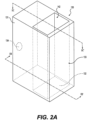
- FIG. 2A is a perspective view of a vaporizer assembly 130 according to some example embodiments.
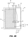
- FIG. 2B is a cross-sectional view along line IIB-IIB' of the vaporizer assembly 130 of FIG. 2A according to some example embodiments.
- FIG. 2C is a cross-sectional view along line IIC-IIC' of the vaporizer assembly 130 of FIG. 2A according to some example embodiments.
- the vaporizer assembly 130 may include a structure that includes the outer housing 131 and conduit assembly 133 collectively defining an internal space 175 that is external to the conduit assembly 133 and is internal to the vaporizer assembly 130.
- the conduit assembly 133 may include a structure having inner surfaces 133I and outer surfaces 133U, where the inner surfaces 133I of the conduit assembly 133 define the conduit 193 that extends continuously between opposite openings 133A and 133B, where opening 133A defines the inlet port 132 and opening 133B defines the outlet port 142 at opposite ends of the conduit 193.
- the first dispensing interface 150-1 may include first and second portions 150-1A, 150-1B, where the first portion 150-1A is the portion of the first dispensing interface 150-1 that extends into the conduit assembly 133 and at least partially into the conduit 193 defined by the inner surfaces 133I of the conduit assembly 133 and where the second portion 150-1B is the portion of the first dispensing interface 150-1 that extends into the internal space 175 and is external to the conduit assembly 133.
- first and second portions 150-1A, 150-1B are integral portions of a unitary piece of material comprising the first dispensing interface 150-1, such that the first and second portions 150-1A, 150-1B are in direct fluid communication with each other and enable unrestricted flow of pre-vapor formulation between the first and second portions 150-1A, 150-1B and therefore between internal space 175 and the conduit 193 through the first dispensing interface 150-1.
- the outer housing 131 and outer surface 133U of the conduit assembly 133 may collectively define an internal space 175 that is isolated from the conduit 193 and is in fluid communication with an exterior of the vaporizer assembly 130 via the fluid port 134 which extends directly between the internal space 175 and the exterior of the vaporizer assembly 130 through the outer housing 131.
- the second dispensing interface 150-2 and the second portion 150-1B of the first dispensing interface 150-1 may occupy the internal space 175, such that the second dispensing interface 150-2 is directly adjacent to and exposed to the fluid port 134 and further is directly adjacent to and coupled to the second portion 150-1B of the first dispensing interface 150-1, and further such that the second dispensing interface 150-2 enables fluid communication between the exterior of the vaporizer assembly 130 via fluid port 134 and the conduit 193 via second dispensing interface 150-2 and at least the second portion 150-1B of the first dispensing interface 150-1.
- the second dispensing interface 150-2 may be in indirect fluid communication with the conduit 193 and with the heating element 136 via the first and second portions 150-1A, 150-1B of the first dispensing interface 150-1. Additionally, the structure of the conduit assembly 133 that isolates the internal space 175 from the conduit 193 and at least the second portion 150-1B of the first dispensing interface 150-1 further isolates the second dispensing interface 150-2 from the conduit 193 and therefore isolates the second dispensing interface 150-2 from at least direct fluid communication with the heating element 136.
- the conduit assembly 133 may define a non-circular conduit 193, including a rectangular cylindrical conduit 193 as shown, but it will be understood that the conduit assembly 133 may define a conduit 193 having any shape, including a circular cylindrical conduit, a non-linear (for example, at least partially curved) conduit, a combination or sub-combination thereof, or the like.
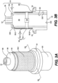
- FIG. 3A is a perspective view of a vaporizer assembly according to some example embodiments.
- FIG. 3B is a cross-sectional view along line IIIB-IIIB' of the vaporizer assembly of FIG. 3A according to some example embodiments.
- the conduit assembly 133 includes a hollow cylindrical inner housing 333, and the first dispensing interface 150-1 extends transversely between opposing inner surfaces 333I of the hollow cylindrical inner housing 333 of the conduit assembly 133. In some example embodiments, including the example embodiments shown in FIGS.
- the second dispensing interface 150-2 includes a hollow cylindrical dispensing interface structure 350-2 that extends around an outer surface 333U of the hollow cylindrical inner housing 333, such that an inner surface 350-2I of the hollow cylindrical dispensing interface structure 350-2 is in direct contact with a surface of the first dispensing interface 150-1, and an outer surface 350-2U of the hollow cylindrical dispensing interface structure 350-2 is exposed to the exterior of the vaporizer assembly 130.
- an inner surface 350-2I of the hollow cylindrical dispensing interface structure 350-2 may be in direct contact with a surface of the second portion 150-1B of the first dispensing interface 150-1 as shown in FIG. 3B .
- some or all of the one or more outer surfaces 350-2U of the hollow cylindrical dispensing interface structure 350-2 may be directly exposed to the exterior of the vaporizer assembly 130, without being exposed via a space, port, conduit, or the like extending through one or more additional structural elements of the vaporizer assembly 130. Accordingly, pre-vapor formulation may be drawn directly into the second dispensing interface 150-2 through any exposed portion of an outer surface 350-2U of the hollow cylindrical dispensing interface structure 350-2.
- the first dispensing interface 150-1 may be in direct contact with the heating element 136, but example embodiments are not limited thereto.
- the second dispensing interface 150-2 is in direct contact with the first dispensing interface 150-1, but example embodiments are not limited thereto.
- the second dispensing interface 150-2 is isolated from direct fluid communication with the conduit 193 by at least the conduit assembly 133 and the first dispensing interface 150-1, but example embodiments are not limited thereto.
- FIGS. 3B is isolated from direct fluid communication with the conduit 193 by at least the conduit assembly 133 and the first dispensing interface 150-1, but example embodiments are not limited thereto.
- the vaporizer assembly 130 may include a connector assembly 138 that is configured to be detachably coupled with a connector assembly associated with a reservoir, such that the vaporizer assembly 130 is configured to be detachably coupled to the reservoir, but example embodiments are not limited thereto.
- the outer housing 131 may include a base structure 308 and cap structure 304.
- the base structure 308 may surround a lower portion of the hollow cylindrical inner housing 333 of the conduit assembly 133, such that a first opening 333A of the hollow cylindrical inner housing 333 defines the inlet port 132 of the vaporizer assembly 130.
- the cap structure 304 may cover at least a portion of the second opening 333B of the hollow cylindrical inner housing 333, such that a portion of the cap structure 304 defines the outlet port 142 of the vaporizer assembly 130.
- the cap structure 304 may include a gasket structure 306 that defines the outlet port 142.
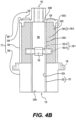
- FIG. 4A is a perspective view of a vaporizer assembly according to some example embodiments.
- FIG. 4B is a cross-sectional view along line IVB-IVB' of the vaporizer assembly of FIG. 4A according to some example embodiments.
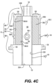
- FIG. 4C is a cross-sectional view along line IVC-IVC' of the vaporizer assembly of FIG. 4A according to some example embodiments.
- the outer housing 131 may include a cylindrical outer housing 302 that at least partially covers the one or more outer surfaces 350-2U of the hollow cylindrical dispensing interface structure 350-2 of the second dispensing interface 150-2.
- the cylindrical outer housing 302 may include one or more ports 302P extending through the cylindrical outer housing 302 to an outer surface 302U that is directly exposed to the exterior of the vaporizer assembly 130, where the port 302P at least partially comprises the fluid port 134.
- the outer housing 131 includes two ports 302P extending through opposite sides of the cylindrical outer housing to opposite sides of the outer surface 302U. It will be understood that, in some example embodiments, the outer housing 131 may include a single port 302P. It will be understood that, in some example embodiments, the outer housing 131 may include more than two ports 302P.
- the hollow cylindrical inner housing 333, the first dispensing interface 150-1, and the second dispensing interface 150-2 may be enclosed within an interior space at least partially defined by an inner surface 302I of the cylindrical outer housing 302, As shown in FIGS. 4A-4C , the hollow cylindrical dispensing interface structure 350-2 of the second dispensing interface 150-2 may be in an annular space 335 that is at least partially defined by the outer surface 333U of the hollow cylindrical inner housing 333 and an inner surface 302I of the cylindrical outer housing 302. Accordingly, as shown in FIGS.
- the cylindrical outer housing 302 may be configured to expose the annular space 335 to an exterior of the vaporizer assembly 130 through the one or more ports 302P, such that the hollow cylindrical dispensing interface structure 350-2 within the annular space 335 is configured to be in direct fluid communication with the exterior of the vaporizer assembly 130 through the one or more ports 302P.
- the outer housing 131 may include a base structure 308 and cap structure 304 in addition to the cylindrical outer housing 302.
- the base structure 308 may surround a lower portion of the hollow cylindrical inner housing 333 of the conduit assembly 133, such that a first opening 333A of the hollow cylindrical inner housing 333 defines the inlet port 132 of the vaporizer assembly 130.
- the base structure 308 may enclose a lower end of the annular space 335 between the cylindrical outer housing 302 and the hollow cylindrical inner housing 333 to therefore at least partially define the annular space 335.
- the cap structure 304 may cover at least an upper end of the annular space 335 and may further cover at least a portion of the second opening 333B of the hollow cylindrical inner housing 333, such that a portion of the cap structure 304 both at least partially defines the annular space 335 and defines the outlet port 142 of the vaporizer assembly 130.
- the cap structure 304 may include a gasket structure 306 that defines the outlet port 142.
- FIG. 5 is a cross-sectional view of a vaporizer assembly according to some example embodiments.
- a dispensing interface assembly 150 that includes a first dispensing interface 150-1 extending through the conduit assembly 133 and coupled to the heating element 136 within the conduit assembly 133 such that the first dispensing interface 150-1 is in direct fluid communication with the conduit assembly 133 and the heating element 136, and further includes a second dispensing interface 150-2 at least partially exposed to an exterior of the vaporizer assembly 130 and isolated from direct fluid communication with the heating element 136 by the first dispensing interface 150-1, may further include one or more additional dispensing interfaces 150-3 interposing between the first and second dispensing interfaces 150-1, 150-2.
- the one or more additional dispensing interfaces 150-3 may be directly coupled to both the first and second dispensing interfaces 150-1, 150-2.
- the first and second dispensing interfaces 150-1, 150-2 may be isolated from direct contact with each other by the one or more additional dispensing interfaces 150-3.
- the one or more additional dispensing interfaces 150-3 may enable fluid communication between the first and second dispensing interfaces 150-1, 150-2.
- pre-vapor formulation drawn into the second dispensing interface 150-2 via one or more ports 302P may be further drawn from the second dispensing interface 150-2 and into the first dispensing interface 150-1 via the one or more additional dispensing interfaces 150-3.
- the one or more additional dispensing interfaces 150-3 may include one or more instances of one or more different wicking materials than either of the first or second dispensing interfaces 150-1, 150-2 and the one or more different wicking materials may have different capacities to draw pre-vapor formulation than one or more of the wicking materials of the first and second dispensing interfaces 150-1, 150-2.
- FIG. 6A is a perspective view of a vaporizer assembly according to some example embodiments.
- FIG. 6B is a perspective view of the vaporizer assembly of FIG. 6A according to some example embodiments.
- FIG. 6C is a cross-sectional view along line VIC-VIC' of the vaporizer assembly of FIG. 6A according to some example embodiments.
- FIG. 7A is a side view of an e-vaping device according to some example embodiments.
- FIG. 7B is a side view of the e-vaping device of FIG. 7A according to some example embodiments.
- FIG. 7C is a cross-sectional view along line VIIC-VIIC' of the e-vaping device of FIG. 7A according to some example embodiments.
- hollow cylindrical inner housing 333 of the conduit assembly 133 may include one or more slot structures 602 into which the first dispensing interface 150-1 may be received and held in place.
- the hollow cylindrical inner housing 333 includes two slot structures 602 extending through opposite sides of the hollow cylindrical inner housing 333. It will be understood that the hollow cylindrical inner housing 33 may include one slot structure 602. It will be understood that the hollow cylindrical inner housing 33 may include more than two slot structures 602.
- the first dispensing interface 150-1 may extend through, and may be structurally supported in place by, opposing slot structures 602 at opposite sides of the hollow cylindrical inner housing 333.
- a width W1 of each slot structure 602 is less than a diameter of the first dispensing interface 150-1, such that a portion of the first dispensing interface 150-1 extending through a slot structure 602 is at least partially compressed by the slot structure 602 to cause the first dispensing interface 150-1 to be held in place by the slot structure 602.
- the first portion 150-1A of the first dispensing interface 150-1 is understood to be a portion of the first dispensing interface 150-1 that extends through conduit 193 between opposing slot structures 602 on opposite sides of the hollow cylindrical inner housing 333 of the conduit assembly 133
- the second portions 150-1B of the first dispensing interface 150-1 may be understood to be the portions of the first dispensing interface 150-1 that extend beyond the slot structures 602 and out of the hollow cylindrical inner housing 333 and into the annular space 335 that extends between the hollow cylindrical inner housing 333 and the cylindrical outer housing 302.
- the hollow cylindrical inner housing 333 and the connector assembly 138 may form part of the same unitary piece of material.
- the hollow cylindrical inner housing 333 and the connector assembly 138 may be two separate elements that can be connected together.
- the hollow cylindrical inner housing 333, the connector assembly 138, and the base structure 308 may form part of the same unitary piece of material.
- the second dispensing interface 150-2 may be directly exposed to conduit 193 through the portions of the slot structures 602 that are not occupied by the first dispensing interface 150-1. However, as shown in FIGS. 6A-6C and FIGS. 7A-7C , in some example embodiments, the second dispensing interface 150-2 may be directly exposed to conduit 193 through the portions of the slot structures 602 that are not occupied by the first dispensing interface 150-1. However, as shown in FIGS.
- the portions of the second dispensing interface 150-2 that are directly exposed to the conduit 193 through the slot structures 602 may be sufficiently distant from the heating element 136 to be isolated from being in direct fluid communication with the heating element 136 by the interposing space of the conduit 193 and slot structures between the exposed second dispensing interface 150-2 and the heating element 136, and the second dispensing interface is further isolated from direct fluid communication with the heating element 136 by the first dispensing interface 150-1.
- the inlet port 132 is at least partially defined by a channel structure 604 that extends into the conduit 193 defined by the hollow cylindrical inner housing 333 of the conduit assembly 133 and extends through the hollow gasket 609 shown in FIG. 6C .
- the channel structure 604 may be coupled to the hollow cylindrical inner housing 333 through the hollow gasket 609.
- the diameter of the inlet port 132 may be less than the diameter of the conduit 193.
- the channel structure 604 may be coupled to the heating element 136 via one or more electrical leads 606-1, 606-2, such that the channel structure 604 may be configured to at least partially enable an electrical coupling between the heating element 136 and a power supply 122 of the power supply assembly 120 when the vapor generator assembly 110 in which the vaporizer assembly 130 is included is coupled to the power supply assembly 120.
Landscapes
- Chemical Vapour Deposition (AREA)
- Feeding, Discharge, Calcimining, Fusing, And Gas-Generation Devices (AREA)
- Infusion, Injection, And Reservoir Apparatuses (AREA)
Claims (20)
- Verdampferbaugruppe (130) für eine E-Dampfvorrichtung (100), die Verdampferbaugruppe (130) umfassend:ein Heizelement (136);eine Leitungsbaugruppe (133), einschließlich einer oder mehrerer Innenflächen, die eine sich durch ein Inneres der Leitungsbaugruppe (133) erstreckende Leitung (193) definieren, sodass die Leitungsbaugruppe (133) zum Lenken von Luft zum Strömen durch die Leitung (193) in Fluidverbindung mit dem Heizelement (136) ausgelegt ist; undeine Abgabeschnittstellenbaugruppe (150), ausgelegt, um sowohl mit der Leitung (193) als auch mit einem Vorratsbehälter (112), der eine Vordampfformulierung enthält, in Fluidverbindung zu stehen, wobei die Abgabeschnittstellenbaugruppe (150) zum Zuführen einer begrenzten Menge der Vordampfformulierung aus dem Vorratsbehälter (112) zu dem Heizelement (136) ausgelegt ist, wobei die Abgabeschnittstellenbaugruppe (150) eine erste Abgabeschnittstelle (150-1) und eine zweite Abgabeschnittstelle (150-2) beinhaltet, wobei sich die erste Abgabeschnittstelle (150-1) durch die Leitung (193) erstreckt und mit dem Heizelement (136) innerhalb der Leitung (193) gekoppelt ist, sodass die erste Abgabeschnittstelle (150-1) in direkter Fluidverbindung mit der Leitung (193) und dem Heizelement (136) steht, wobei ein Abschnitt der zweiten Abgabeschnittstelle (150-2) einer Außenseite der Verdampferbaugruppe (130) ausgesetzt ist, sodass die zweite Abgabeschnittstelle (150-2) ausgelegt ist, um über den Abschnitt der zweiten Abgabeschnittstelle (150-2) in direkter Fluidverbindung mit dem Vorratsbehälter (112) zu stehen, die zweite Abgabeschnittstelle (150-2) durch die erste Abgabeschnittstelle (150-1) von der direkten Fluidverbindung mit dem Heizelement (136) isoliert ist, die erste Abgabeschnittstelle (150-1) durch die zweite Abgabeschnittstelle (150-2) von der direkten Fluidverbindung mit dem Vorratsbehälter (112) isoliert ist, wobei die zweite Abgabeschnittstelle (150-2) zum Begrenzen einer Strömung der Vordampfformulierung aus dem Vorratsbehälter (112) zu der ersten Abgabeschnittstelle (150-1) ausgelegt ist, wobei die erste Abgabeschnittstelle (150-1) zum Unterstützen einer ersten maximalen Strömungsgeschwindigkeit der Vordampfformulierung durch die interne Struktur der ersten Abgabeschnittstelle (150-1) ausgelegt ist, wobei die zweite Abgabeschnittstelle (150-2) zum Unterstützen einer zweiten maximalen Strömungsgeschwindigkeit der Vordampfformulierung durch die interne Struktur der zweiten Abgabeschnittstelle (150-2) ausgelegt ist, und wobei die Größe der zweiten maximalen Strömungsgeschwindigkeit gleich oder kleiner als 50 Prozent der Größe der ersten maximalen Strömungsgeschwindigkeit ist.
- Verdampferbaugruppe (130) nach Anspruch 1, wobeidie Leitungsbaugruppe (133) ein hohlzylindrisches Innengehäuse (333) beinhaltet,sich die erste Abgabeschnittstelle (150-1) quer zwischen gegenüberliegenden Innenflächen des hohlzylindrischen Innengehäuses (333) erstreckt, unddie zweite Abgabeschnittstelle (150-2) eine hohlzylindrische Abgabeschnittstellenstruktur (350-2) beinhaltet, die sich um eine Außenfläche des hohlzylindrischen Innengehäuses (333) erstreckt, wobei eine Innenfläche der hohlzylindrischen Abgabeschnittstellenstruktur (350-2) in direktem Kontakt mit einer Fläche der ersten Abgabeschnittstelle (150-1) steht, wobei eine Fläche der hohlzylindrischen Abgabeschnittstellenstruktur (350-2) der Außenseite der Verdampferbaugruppe (130) ausgesetzt ist,optional, wobei die Verdampferbaugruppe (130) ferner umfasst:ein zylindrisches Außengehäuse (302), einschließlich eines sich durch das zylindrische Außengehäuse (302,) das hohlzylindrische Innengehäuse (333), die erste Abgabeschnittstelle (150-1) und die zweite Abgabeschnittstelle (150-2) erstreckenden Anschlusses (302P), der innerhalb eines durch das zylindrische Außengehäuse (302) definierten Innenraums eingeschlossen ist,wobei sich die hohlzylindrische Abgabeschnittstellenstruktur (350-2) in einem ringförmigen Raum befindet, der durch die Außenfläche des hohlzylindrischen Innengehäuses (333) und eine Innenfläche des zylindrischen Außengehäuses (302) definiert ist, wobei das zylindrische Außengehäuse (302) ausgelegt ist, den ringförmigen Raum über den Anschluss (302P) dem Vorratsbehälter (112) derart auszusetzen, dass die hohlzylindrische Abgabeschnittstellenstruktur (350-2) innerhalb des ringförmigen Raums ausgelegt ist, über den Anschluss (302P) in direkter Fluidverbindung mit dem Vorratsbehälter (112) zu stehen.
- Verdampferbaugruppe (130) nach Anspruch 1 oder 2, wobei die erste Abgabeschnittstelle (150-1) in direktem Kontakt mit dem Heizelement (136) steht.
- Verdampferbaugruppe (130) nach einem beliebigen vorhergehenden Anspruch, wobei die zweite Abgabeschnittstelle (150-2) in direktem Kontakt mit der ersten Abgabeschnittstelle (150-1) steht.
- Verdampferbaugruppe (130) nach einem beliebigen vorhergehenden Anspruch, wobei die zweite Abgabeschnittstelle (150-2) von der direkten Fluidverbindung mit der Leitung (193) isoliert ist.
- Verdampferbaugruppe (130) nach einem beliebigen vorhergehenden Anspruch, wobei die Verdampferbaugruppe (130) zum lösbaren Koppeln mit dem Vorratsbehälter (120) ausgelegt ist.
- Patrone für eine E-Dampfvorrichtung (100), die Patrone umfassend:einen zum Aufnehmen einer Vordampfformulierung ausgelegten Vorratsbehälter (112); undeine mit dem Vorratsbehälter (112) gekoppelte Verdampferbaugruppe (130), wobei die Verdampferbaugruppe (130) zum Ziehen einer Vordampfformulierung aus dem Vorratsbehälter (112) ausgelegt ist, wobei die Verdampferbaugruppe (130) ferner zum Erwärmen der gezogenen Vordampfformulierung zum Bilden eines erzeugten Dampfes ausgelegt ist, wobei die Verdampferbaugruppe (130) beinhaltet:ein Heizelement (136);eine Leitungsbaugruppe (133), einschließlich einer oder mehrerer Innenflächen, die eine sich durch ein Inneres der Leitungsbaugruppe (133) erstreckende Leitung (193) definieren, sodass die Leitungsbaugruppe (133) zum Lenken von Luft zum Strömen durch die Leitung (193) in Fluidverbindung mit dem Heizelement (136) ausgelegt ist; undeine Abgabeschnittstellenbaugruppe (150), ausgelegt, um sowohl mit der Leitung (193) als auch mit dem Vorratsbehälter (112) in Fluidverbindung zu stehen, wobei die Abgabeschnittstellenbaugruppe (150) zum Zuführen einer begrenzten Menge der Vordampfformulierung aus dem Vorratsbehälter (112) zu dem Heizelement (136) ausgelegt ist, wobei die Abgabeschnittstellenbaugruppe (150) eine erste Abgabeschnittstelle (150-1) und eine zweite Abgabeschnittstelle (150-2) beinhaltet, wobei sich die erste Abgabeschnittstelle (150-1) durch die Leitung (193) erstreckt und mit dem Heizelement (136) innerhalb der Leitung (193) gekoppelt ist, sodass die erste Abgabeschnittstelle (150-1) in direkter Fluidverbindung mit der Leitung (193) und dem Heizelement (136) steht, wobei ein Abschnitt der zweiten Abgabeschnittstelle (150-2) einer Außenseite der Verdampferbaugruppe (130) ausgesetzt ist, sodass die zweite Abgabeschnittstelle (150-2) ausgelegt ist, um über den Abschnitt der zweiten Abgabeschnittstelle (150-2) in direkter Fluidverbindung mit dem Vorratsbehälter (112) zu stehen, die zweite Abgabeschnittstelle (150-2) durch die erste Abgabeschnittstelle (150-1) von der direkten Fluidverbindung mit dem Heizelement (136) isoliert ist, die erste Abgabeschnittstelle (150-1) durch die zweite Abgabeschnittstelle (150-2) von der direkten Fluidverbindung mit dem Vorratsbehälter (112) isoliert ist, wobei die zweite Abgabeschnittstelle (150-2) zum Begrenzen einer Strömung der Vordampfformulierung aus dem Vorratsbehälter (112) zu der ersten Abgabeschnittstelle (150-1) ausgelegt ist, wobei die erste Abgabeschnittstelle (150-1) zum Unterstützen einer ersten maximalen Strömungsgeschwindigkeit der Vordampfformulierung durch die interne Struktur der ersten Abgabeschnittstelle (150-1) ausgelegt ist, wobei die zweite Abgabeschnittstelle (150-2) zum Unterstützen einer zweiten maximalen Strömungsgeschwindigkeit der Vordampfformulierung durch die interne Struktur der zweiten Abgabeschnittstelle (150-2) ausgelegt ist, und wobei die Größe der zweiten maximalen Strömungsgeschwindigkeit gleich oder kleiner als 50 Prozent der Größe der ersten maximalen Strömungsgeschwindigkeit ist.
- Patrone nach Anspruch 7, wobeidie Leitungsbaugruppe (133) ein hohlzylindrisches Innengehäuse (333) beinhaltet,sich die erste Abgabeschnittstelle (150-1) quer zwischen gegenüberliegenden Innenflächen des hohlzylindrischen Innengehäuses (333) erstreckt, unddie zweite Abgabeschnittstelle (150-2) eine hohlzylindrische Abgabeschnittstellenstruktur (350-2) beinhaltet, die sich um eine Außenfläche des hohlzylindrischen Innengehäuses (333) erstreckt, wobei eine Innenfläche der hohlzylindrischen Abgabeschnittstellenstruktur (350-2) in direktem Kontakt mit einer Fläche der ersten Abgabeschnittstelle (150-1) steht, wobei eine Fläche der hohlzylindrischen Abgabeschnittstellenstruktur (350-2) der Außenseite der Verdampferbaugruppe (130) ausgesetzt ist,optional, wobei die Verdampferbaugruppe (130) ferner beinhaltet:ein zylindrisches Außengehäuse (302), einschließlich eines sich durch das zylindrische Außengehäuse (302,) das hohlzylindrische Innengehäuse (333), die erste Abgabeschnittstelle (150-1) und die zweite Abgabeschnittstelle (150-2) erstreckenden Anschlusses (302P), der innerhalb eines durch das zylindrische Außengehäuse (302) definierten Innenraums eingeschlossen ist,wobei sich die hohlzylindrische Abgabeschnittstellenstruktur (350-2) der zweiten Abgabeschnittstelle (150-2) in einem ringförmigen Raum befindet, der durch die Außenfläche des hohlzylindrischen Innengehäuses (333) und eine Innenfläche des zylindrischen Außengehäuses (302) definiert ist, wobei das zylindrische Außengehäuse (302) ausgelegt ist, den ringförmigen Raum über den Anschluss (302P) dem Vorratsbehälter (112) derart auszusetzen, dass die hohlzylindrische Abgabeschnittstellenstruktur (350-2) innerhalb des ringförmigen Raums ausgelegt ist, über den Anschluss (302P) in direkter Fluidverbindung mit dem Vorratsbehälter (112) zu stehen.
- Patrone nach Anspruch 7 oder 8, wobei die erste Abgabeschnittstelle (150-1) in direktem Kontakt mit dem Heizelement (136) steht.
- Patrone nach einem der Ansprüche 7 bis 9, wobei die zweite Abgabeschnittstelle (150-2) in direktem Kontakt mit der ersten Abgabeschnittstelle (150-1) steht.
- Patrone nach einem der Ansprüche 7 bis 10, wobei die zweite Abgabeschnittstelle (150-2) von der direkten Fluidverbindung mit der Leitung (193) isoliert ist.
- Patrone nach einem der Ansprüche 7 bis 11, wobei die Verdampferbaugruppe (130) lösbar mit dem Vorratsbehälter (112) gekoppelt ist.
- E-Dampfvorrichtung (100), wobei die E-Dampfvorrichtung (100) umfasst:
eine Patrone, wobei die Patrone beinhaltet:einen zum Aufnehmen einer Vordampfformulierung ausgelegten Vorratsbehälter (112) undeine mit dem Vorratsbehälter (112) gekoppelte Verdampferbaugruppe (130), wobei die Verdampferbaugruppe (130) zum Ziehen einer Vordampfformulierung aus dem Vorratsbehälter (112) ausgelegt ist, wobei die Verdampferbaugruppe (130) ferner zum Erwärmen der gezogenen Vordampfformulierung zum Bilden eines erzeugten Dampfes ausgelegt ist, wobei die Verdampferbaugruppe (130) beinhaltet:ein Heizelement (136);eine Leitungsbaugruppe (133), einschließlich einer oder mehrerer Innenflächen, die eine sich durch ein Inneres der Leitungsbaugruppe (133) erstreckende Leitung (193) definieren, sodass die Leitungsbaugruppe (133) zum Lenken von Luft zum Strömen durch die Leitung (193) in Fluidverbindung mit dem Heizelement (136) ausgelegt ist; undeine Abgabeschnittstellenbaugruppe (150), ausgelegt, um sowohl mit der Leitung (193) als auch mit dem Vorratsbehälter (112) in Fluidverbindung zu stehen, wobei die Abgabeschnittstellenbaugruppe (150) zum Zuführen einer begrenzten Menge der Vordampfformulierung aus dem Vorratsbehälter (112) zu dem Heizelement (136) ausgelegt ist, wobei die Abgabeschnittstellenbaugruppe (150) eine erste Abgabeschnittstelle (150-1) und eine zweite Abgabeschnittstelle (150-2) beinhaltet, wobei sich die erste Abgabeschnittstelle (150-1) durch die Leitung (193) erstreckt und mit dem Heizelement (136) innerhalb der Leitung (193) gekoppelt ist, sodass die erste Abgabeschnittstelle (150-1) in direkter Fluidverbindung mit der Leitung (193) und dem Heizelement (136) steht, wobei ein Abschnitt der zweiten Abgabeschnittstelle (150-2) einer Außenseite der Verdampferbaugruppe (130) ausgesetzt ist, sodass die zweite Abgabeschnittstelle (150-2) ausgelegt ist, um über den Abschnitt der zweiten Abgabeschnittstelle (150-2) in direkter Fluidverbindung mit dem Vorratsbehälter (112) zu stehen, die zweite Abgabeschnittstelle (150-2) durch die erste Abgabeschnittstelle (150-1) von der direkten Fluidverbindung mit dem Heizelement (136) isoliert ist, die erste Abgabeschnittstelle (150-1) durch die zweite Abgabeschnittstelle (150-2) von der direkten Fluidverbindung mit dem Vorratsbehälter (112) isoliert ist, wobei die zweite Abgabeschnittstelle (150-2) zum Begrenzen einer Strömung der Vordampfformulierung aus dem Vorratsbehälter (112) zu der ersten Abgabeschnittstelle (150-1) ausgelegt ist, wobei die erste Abgabeschnittstelle (150-1) zum Unterstützen einer ersten maximalen Strömungsgeschwindigkeit der Vordampfformulierung durch die interne Struktur der ersten Abgabeschnittstelle (150-1) ausgelegt ist, wobei die zweite Abgabeschnittstelle (150-2) zum Unterstützen einer zweiten maximalen Strömungsgeschwindigkeit der Vordampfformulierung durch die interne Struktur der zweiten Abgabeschnittstelle (150-2) ausgelegt ist, und wobei die Größe der zweiten maximalen Strömungsgeschwindigkeit gleich oder kleiner als 50 Prozent der Größe der ersten maximalen Strömungsgeschwindigkeit ist; undeine mit der Patrone gekoppelte Energieversorgungsbaugruppe (120), wobei die Energieversorgungsbaugruppe (120) eine Energieversorgung (122) beinhaltet, wobei die Energieversorgungsbaugruppe (120) zum Zuführen elektrischer Energie von der Energieversorgung (122) zu der Verdampferbaugruppe (130) ausgelegt ist. - E-Dampfvorrichtung (100) nach Anspruch 13, wobeidie Leitungsbaugruppe (133) ein hohlzylindrisches Innengehäuse (333) beinhaltet,sich die erste Abgabeschnittstelle (150-1) quer zwischen gegenüberliegenden Innenflächen des hohlzylindrischen Innengehäuses (333) erstreckt, unddie zweite Abgabeschnittstelle (150-2) eine hohlzylindrische Abgabeschnittstellenstruktur (350-2) beinhaltet, die sich um eine Außenfläche des hohlzylindrischen Innengehäuses (333) erstreckt, wobei eine Innenfläche der hohlzylindrischen Abgabeschnittstellenstruktur (350-2) in direktem Kontakt mit einer Fläche der ersten Abgabeschnittstelle (150-1) steht, wobei eine Fläche der hohlzylindrischen Abgabeschnittstellenstruktur (350-2) der Außenseite der Verdampferbaugruppe (130) ausgesetzt ist,optional, wobei die Verdampferbaugruppe (130) ferner beinhaltet:ein zylindrisches Außengehäuse (302), einschließlich eines sich durch das zylindrische Außengehäuse (302,) das hohlzylindrische Innengehäuse (333), die erste Abgabeschnittstelle (150-1) und die zweite Abgabeschnittstelle (150-2) erstreckenden Anschlusses (302P), der innerhalb eines durch das zylindrische Außengehäuse (302) definierten Innenraums eingeschlossen ist,wobei sich die hohlzylindrische Abgabeschnittstellenstruktur (350-2) der zweiten Abgabeschnittstelle (150-2) in einem ringförmigen Raum befindet, der durch die Außenfläche des hohlzylindrischen Innengehäuses (333) und eine Innenfläche des zylindrischen Außengehäuses (302) definiert ist, wobei das zylindrische Außengehäuse (302) ausgelegt ist, den ringförmigen Raum über den Anschluss (302P) dem Vorratsbehälter (112) derart auszusetzen, dass die hohlzylindrische Abgabeschnittstellenstruktur (350-2) innerhalb des ringförmigen Raums ausgelegt ist, über den Anschluss (302P) in direkter Fluidverbindung mit dem Vorratsbehälter (112) zu stehen.
- E-Dampfvorrichtung (100) nach Anspruch 13 oder 14, wobei die erste Abgabeschnittstelle (150-1) in direktem Kontakt mit dem Heizelement (136) steht.
- E-Dampfvorrichtung (100) nach einem der Ansprüche 13 bis 15, wobei die zweite Abgabeschnittstelle (150-2) in direktem Kontakt mit der ersten Abgabeschnittstelle (150-1) steht.
- E-Dampfvorrichtung (100) nach einem der Ansprüche 13 bis 16, wobei die zweite Abgabeschnittstelle (150-2) von der direkten Fluidverbindung mit der Leitung (193) isoliert ist.
- E-Dampfvorrichtung (100) nach einem der Ansprüche 13 bis 17, wobei die Patrone lösbar mit der Energieversorgungsbaugruppe (120) gekoppelt ist.
- E-Dampfvorrichtung (100) nach einem der Ansprüche 13 bis 18, wobei die Verdampferbaugruppe (130) lösbar mit dem Vorratsbehälter (112) gekoppelt ist.
- E-Dampfvorrichtung (100) nach einem der Ansprüche 13 bis 19, wobei die Energieversorgung (122) eine wiederaufladbare Batterie ist.
Applications Claiming Priority (2)
| Application Number | Priority Date | Filing Date | Title |
|---|---|---|---|
| US16/196,749 US11304448B2 (en) | 2018-11-20 | 2018-11-20 | Vaporizer assembly |
| PCT/EP2019/081987 WO2020104557A1 (en) | 2018-11-20 | 2019-11-20 | Vaporizer assembly and components thereof |
Publications (3)
| Publication Number | Publication Date |
|---|---|
| EP3883403A1 EP3883403A1 (de) | 2021-09-29 |
| EP3883403C0 EP3883403C0 (de) | 2024-08-14 |
| EP3883403B1 true EP3883403B1 (de) | 2024-08-14 |
Family
ID=68699401
Family Applications (1)
| Application Number | Title | Priority Date | Filing Date |
|---|---|---|---|
| EP19809744.6A Active EP3883403B1 (de) | 2018-11-20 | 2019-11-20 | Verdampfereinheit und komponenten dafür |
Country Status (6)
| Country | Link |
|---|---|
| US (2) | US11304448B2 (de) |
| EP (1) | EP3883403B1 (de) |
| JP (1) | JP7520827B2 (de) |
| KR (1) | KR102747816B1 (de) |
| CN (1) | CN112930124B (de) |
| WO (1) | WO2020104557A1 (de) |
Families Citing this family (6)
| Publication number | Priority date | Publication date | Assignee | Title |
|---|---|---|---|---|
| EP3729311B1 (de) | 2017-12-21 | 2025-05-14 | Juul Labs, Inc. | Verdampfersteuerungen |
| US11071326B2 (en) | 2018-11-20 | 2021-07-27 | Altria Client Services Llc | E-vaping device |
| US11304448B2 (en) * | 2018-11-20 | 2022-04-19 | Altria Client Services Llc | Vaporizer assembly |
| US12083251B2 (en) * | 2018-12-20 | 2024-09-10 | Aeron Lifestyle Technology, Inc. | USB scent diffuser |
| US11925208B2 (en) | 2020-06-25 | 2024-03-12 | Altria Client Services Llc | Non-nicotine e-vaping device |
| CN117279530A (zh) * | 2021-05-18 | 2023-12-22 | 日本烟草产业株式会社 | 气溶胶发生体及香味吸取器 |
Citations (1)
| Publication number | Priority date | Publication date | Assignee | Title |
|---|---|---|---|---|
| WO2016154994A1 (zh) * | 2015-04-02 | 2016-10-06 | 惠州市吉瑞科技有限公司 | 雾化组件和电子烟 |
Family Cites Families (117)
| Publication number | Priority date | Publication date | Assignee | Title |
|---|---|---|---|---|
| DE3712977A1 (de) | 1987-04-16 | 1988-11-03 | Lentjes Ag | Vorrichtung zum katalytischen entsticken von rauchgasen |
| WO2013181797A1 (zh) | 2012-06-05 | 2013-12-12 | Liu Qiuming | 电子烟及其吸杆 |
| US9308336B2 (en) | 2012-09-19 | 2016-04-12 | Kyle D. Newton | Refill diverter for electronic cigarette |
| CN103960781A (zh) | 2013-09-29 | 2014-08-06 | 深圳市麦克韦尔科技有限公司 | 电子烟 |
| US9727747B1 (en) * | 2012-12-21 | 2017-08-08 | Mobile Iron, Inc. | Location and time based mobile app policies |
| CN105163609B (zh) | 2013-03-26 | 2018-06-12 | 吉瑞高新科技股份有限公司 | 电子烟 |
| US20150196055A1 (en) | 2013-04-15 | 2015-07-16 | Kimree Hi-Tech Inc. | Electronic cigarette |
| KR102278193B1 (ko) | 2013-05-21 | 2021-07-19 | 필립모리스 프로덕츠 에스.에이. | 전기 가열식 에어로졸 전달 시스템 |
| CN111642812A (zh) | 2013-06-14 | 2020-09-11 | 尤尔实验室有限公司 | 电子汽化设备中的具有单独的可汽化材料的多个加热元件 |
| CN203538369U (zh) | 2013-08-26 | 2014-04-16 | 高珍 | 一种可调气流的电子烟雾化器 |
| US10251423B2 (en) | 2013-09-13 | 2019-04-09 | Nicodart, Inc. | Programmable electronic vaporizing apparatus and smoking cessation system |
| CN203505590U (zh) | 2013-10-29 | 2014-04-02 | 深圳市康尔科技有限公司 | 具有气流调节功能的雾化器 |
| US10039321B2 (en) | 2013-11-12 | 2018-08-07 | Vmr Products Llc | Vaporizer |
| TR201904305T4 (tr) | 2014-02-10 | 2019-04-22 | Philip Morris Products Sa | Bir ısıtıcı düzeneğe sahip bir aerosol - üretici sistem ve akışkan geçirgen bir ısıtıcı düzeneğe sahip bir aerosol - üretici sistem için bir kartuş. |
| DE202014001717U1 (de) | 2014-02-27 | 2015-05-28 | Xeo Holding GmbH | Funktionsmodul für eine Rauchvorrichtung |
| DE202014001718U1 (de) | 2014-02-27 | 2015-05-28 | Xeo Holding GmbH | Rauchvorrichtung |
| GB201413028D0 (en) | 2014-02-28 | 2014-09-03 | Beyond Twenty Ltd | Beyond 5 |
| CN203748684U (zh) | 2014-04-08 | 2014-08-06 | 深圳市康尔科技有限公司 | 可调气流雾化器 |
| CN203860454U (zh) | 2014-04-21 | 2014-10-08 | 申敏良 | 一种电子烟雾化器用气流调节组件 |
| CN203860455U (zh) | 2014-04-21 | 2014-10-08 | 申敏良 | 一种可调节气流的电子烟用雾化器组件 |
| US9814264B2 (en) | 2014-04-23 | 2017-11-14 | Vitor Manuel ROCHA DINIS | Personal vaporizer system |
| CN203851819U (zh) | 2014-05-22 | 2014-10-01 | 孔磊 | 可调节烟雾量的电子烟雾化器 |
| US9955726B2 (en) | 2014-05-23 | 2018-05-01 | Rai Strategic Holdings, Inc. | Sealed cartridge for an aerosol delivery device and related assembly method |
| CN104082863B (zh) | 2014-07-08 | 2017-04-26 | 深圳市康尔科技有限公司 | 顶部注液底部换发热组件的电子烟 |
| WO2016004576A1 (zh) | 2014-07-08 | 2016-01-14 | 深圳市康尔科技有限公司 | 顶部注液底部换发热组件的电子烟 |
| CN203986123U (zh) | 2014-07-16 | 2014-12-10 | 深圳市艾维普思科技有限公司 | 一种可改变进气方向的电子烟 |
| US20160262452A1 (en) | 2014-07-17 | 2016-09-15 | Shenzhen Kanger Technology Co., Ltd | Electronic cigarettes having adjustable vaporizer |
| CN203986125U (zh) | 2014-07-17 | 2014-12-10 | 深圳市康尔科技有限公司 | 一种电子烟 |
| CN105310112B (zh) | 2014-07-31 | 2017-12-05 | 深圳市艾维普思科技有限公司 | 一种电子水烟结构 |
| CN204048044U (zh) | 2014-08-26 | 2014-12-31 | 付云峰 | 一种电子烟雾化器气流调节结构 |
| WO2016037362A1 (zh) | 2014-09-12 | 2016-03-17 | 深圳麦克韦尔股份有限公司 | 电子烟及其空气开关装置 |
| EP3760059B1 (de) | 2014-09-17 | 2022-10-26 | Fontem Holdings 4 B.V. | Vorrichtung zum speichern und verdampfen flüssiger medien |
| CN204104840U (zh) | 2014-09-23 | 2015-01-21 | 陈悦强 | 一种可调气流的电子烟 |
| CN106793831B (zh) | 2014-09-25 | 2019-10-25 | 惠州市吉瑞科技有限公司 | 一种雾化组件及电子烟 |
| EA201790759A1 (ru) | 2014-10-03 | 2017-07-31 | Олтриа Клайент Сервисиз Ллк | Электронное вейпинговое устройство и его компоненты |
| US10219541B2 (en) | 2014-10-29 | 2019-03-05 | Lubby Holdings, LLC | Cartridge cover for personal vaporizer |
| WO2016073726A2 (en) | 2014-11-05 | 2016-05-12 | Altria Client Services Llc. | Reservoir filling system for an electronic vaping device |
| WO2016090426A1 (en) | 2014-12-08 | 2016-06-16 | Kinchington Holdings Pty Ltd | Electronic cigarette |
| EP3031339A1 (de) | 2014-12-09 | 2016-06-15 | Xiaochun Zhu | Von oben nachfüllbare elektronische zigaretten |
| US20160157522A1 (en) | 2014-12-09 | 2016-06-09 | Xiaochun Zhu | Vaporizer and electronic cigarettes having the vaporizer |
| AR103016A1 (es) | 2014-12-15 | 2017-04-12 | Philip Morris Products Sa | Sistemas generadores de aerosol y métodos para dirigir un flujo de aire hacia dentro de un sistema generador de aerosol calentado eléctricamente |
| CN104544568B (zh) | 2014-12-25 | 2017-12-01 | 东莞市哈维电子科技有限公司 | 一种可调节电阻和气流大小的电子烟雾化器 |
| WO2016119098A1 (zh) | 2015-01-26 | 2016-08-04 | 惠州市吉瑞科技有限公司 | 一种雾化组件及电子烟 |
| CN207285189U (zh) | 2015-03-06 | 2018-05-01 | 惠州市吉瑞科技有限公司深圳分公司 | 雾化组件和电子烟 |
| CN107427070A (zh) | 2015-03-17 | 2017-12-01 | 惠州市吉瑞科技有限公司 | 一种雾化组件及电子烟 |
| WO2016145612A1 (zh) | 2015-03-17 | 2016-09-22 | 惠州市吉瑞科技有限公司 | 一种雾化组件及电子烟 |
| US20160286860A1 (en) | 2015-03-31 | 2016-10-06 | Richard Reed FLAYLER | Electronic vaporizing device having an automatically re-sealable reservoir tank |
| CN204540839U (zh) | 2015-04-01 | 2015-08-12 | 深圳市联君烟博士电子技术有限责任公司 | 保护罩隐蔽式进气电子雾化器 |
| WO2016169063A1 (zh) | 2015-04-24 | 2016-10-27 | 深圳麦克韦尔股份有限公司 | 电子烟及其雾化装置 |
| US10772353B2 (en) | 2015-04-28 | 2020-09-15 | Shenzhen Smoore Technology Limited | Inhaler and atomization component thereof |
| WO2016201602A1 (zh) | 2015-06-15 | 2016-12-22 | 惠州市吉瑞科技有限公司深圳分公司 | 一种电子烟 |
| CN205082671U (zh) | 2015-06-19 | 2016-03-16 | 卓尔悦(常州)电子科技有限公司 | 雾化器及其气溶胶发生装置 |
| WO2016208757A1 (ja) | 2015-06-26 | 2016-12-29 | 日本たばこ産業株式会社 | 霧化ユニット |
| CN204861175U (zh) | 2015-07-14 | 2015-12-16 | 卓尔悦(常州)电子科技有限公司 | 电子烟 |
| US11504489B2 (en) | 2015-07-17 | 2022-11-22 | Rai Strategic Holdings, Inc. | Contained liquid system for refilling aerosol delivery devices |
| US10721965B2 (en) * | 2015-07-29 | 2020-07-28 | Altria Client Services Llc | E-vapor device including heater structure with recessed shell layer |
| CN204907937U (zh) | 2015-08-26 | 2015-12-30 | 卓尔悦(常州)电子科技有限公司 | 雾化器及其气溶胶发生装置 |
| CN106174704B (zh) | 2015-09-30 | 2021-05-07 | 深圳市合元科技有限公司 | 可填充装置 |
| WO2017063535A1 (zh) | 2015-10-13 | 2017-04-20 | 常州聚为智能科技有限公司 | 雾化器及其电子烟 |
| US11006667B2 (en) | 2015-10-16 | 2021-05-18 | 14Th Round Inc. | Assembly for providing chemicals for smokeless administration, a disposable tank, and a method of using the same |
| CN205322939U (zh) | 2015-10-27 | 2016-06-22 | 深圳市杰仕博科技有限公司 | 隔热吸嘴 |
| US10021910B2 (en) * | 2015-11-13 | 2018-07-17 | Altria Client Services Llc | E-vaping section and e-vaping device, and a method of manufacturing thereof |
| CN205196999U (zh) | 2015-11-23 | 2016-05-04 | 深圳市合元科技有限公司 | 雾化器及电子烟 |
| EP3383461B1 (de) * | 2015-11-30 | 2020-07-29 | Philip Morris Products S.a.s. | Nichtbrennbare rauchvorrichtung und elemente davon |
| CN105411006A (zh) | 2015-12-28 | 2016-03-23 | 昂纳自动化技术(深圳)有限公司 | 一种可更换雾化芯的电子烟 |
| CN205358220U (zh) | 2016-01-06 | 2016-07-06 | 常州聚为智能科技有限公司 | 雾化器及其电子烟 |
| US10834965B2 (en) | 2016-01-20 | 2020-11-17 | Shenzhen Kanger Technology Co., Ltd. | Ceramic vaporizer and electronic cigarettes having the ceramic vaporizer |
| CN205456070U (zh) | 2016-02-26 | 2016-08-17 | 深圳市合元科技有限公司 | 可注液雾化器以及使用该雾化器的电子烟 |
| CN205390305U (zh) | 2016-02-26 | 2016-07-27 | 申敏良 | 一种电子烟雾化器 |
| US10368580B2 (en) * | 2016-03-08 | 2019-08-06 | Altria Client Services Llc | Combined cartridge for electronic vaping device |
| WO2017156733A1 (en) | 2016-03-16 | 2017-09-21 | Xiaochun Zhu | Temper-proof locking mechanisms and electronic cigarettes having the same |
| CN205624467U (zh) | 2016-03-21 | 2016-10-12 | 深圳市合元科技有限公司 | 一种烟油加热组件及包括该烟油加热组件的电子烟和雾化器 |
| US10617152B2 (en) * | 2016-03-31 | 2020-04-14 | Altria Client Services Llc | Aerosol-generating system with separate capsule and vaporizer |
| US10463076B2 (en) | 2016-04-11 | 2019-11-05 | Altria Client Services Llc | Electronic vaping device |
| CN205695706U (zh) | 2016-04-11 | 2016-11-23 | 深圳麦克韦尔股份有限公司 | 电子烟及其雾化器 |
| CN205757176U (zh) | 2016-04-14 | 2016-12-07 | 深圳市合元科技有限公司 | 雾化器及电子烟 |
| CN105815810A (zh) | 2016-04-20 | 2016-08-03 | 云南中烟工业有限责任公司 | 一种烟气浓度可调的烟嘴 |
| CN105876868B (zh) | 2016-05-06 | 2019-05-03 | 卓尔悦欧洲控股有限公司 | 雾化器及其电子烟 |
| CN205728065U (zh) | 2016-05-10 | 2016-11-30 | 深圳市合元科技有限公司 | 吸嘴组件、雾化器及电子烟 |
| CN205794806U (zh) | 2016-06-07 | 2016-12-14 | 深圳市新宜康科技有限公司 | 上组装电子烟雾化器 |
| CN205794807U (zh) | 2016-06-08 | 2016-12-14 | 刘团芳 | 一种顶部进气顶部调气流雾化器 |
| US10111468B2 (en) | 2016-06-13 | 2018-10-30 | Db Innovation Inc. | Vaporization device |
| CN105942581B (zh) | 2016-06-24 | 2019-03-29 | 深圳市新宜康科技股份有限公司 | 上出芯电子烟雾化器及一次性储液瓶 |
| US9795169B1 (en) | 2016-07-05 | 2017-10-24 | Xiaochun Zhu | Replaceable vaporizer assembly and electronic cigarette having the same |
| US10111469B2 (en) | 2016-07-05 | 2018-10-30 | Shenzhen Kanger Technology Co., Ltd. | Vaporizers having top air intake and electronic cigarette having the same |
| US10881139B2 (en) | 2016-07-07 | 2021-01-05 | Altria Client Services Llc | Non-combustible vaping element with tobacco insert |
| US9993025B2 (en) | 2016-07-25 | 2018-06-12 | Fontem Holdings 1 B.V. | Refillable electronic cigarette clearomizer |
| CN205865989U (zh) | 2016-08-08 | 2017-01-11 | 卓尔悦欧洲控股有限公司 | 具有调节反馈组件的雾化器及其电子烟 |
| CN107865461B (zh) | 2016-09-22 | 2021-03-30 | 卓尔悦欧洲控股有限公司 | 雾化头、雾化器及具有该雾化器的电子烟 |
| US11660403B2 (en) | 2016-09-22 | 2023-05-30 | Juul Labs, Inc. | Leak-resistant vaporizer device |
| US10004265B2 (en) | 2016-10-12 | 2018-06-26 | Altria Client Services Llc | Application of a multi-chamber cartridge |
| CN106418714B (zh) | 2016-10-27 | 2019-04-05 | 深圳瀚星翔科技有限公司 | 电子雾化器 |
| CN206380711U (zh) | 2016-10-28 | 2017-08-08 | 深圳市金卓恒电子科技有限公司 | 连体机械电子烟 |
| US10015991B1 (en) | 2016-12-29 | 2018-07-10 | Altria Client Services Llc | Hybrid E-vaping cartridge, E-vaping device including a hybrid E-vaping cartridge, and method of making thereof |
| CN206413751U (zh) | 2017-01-09 | 2017-08-18 | 深圳市赛诺邦格科技有限公司 | 一种调节环可拆卸的雾化器及电子烟 |
| CN206453250U (zh) | 2017-01-13 | 2017-09-01 | 常州市派腾电子技术服务有限公司 | 一种雾化器及电子烟 |
| US11006670B2 (en) | 2017-01-16 | 2021-05-18 | Shenzhen First Union Technology Co., Ltd. | Atomizer for electronic cigarette |
| CN206534130U (zh) | 2017-02-07 | 2017-10-03 | 常州市派腾电子技术服务有限公司 | 电池组件及其电子烟 |
| CN108567166A (zh) | 2017-03-09 | 2018-09-25 | 深圳市康尔科技有限公司 | 电子烟液分离机构以及带有电子烟液分离机构的电子烟 |
| CN207306063U (zh) | 2017-03-17 | 2018-05-04 | 东莞市伯科电子科技有限公司 | 一种新型雾化器 |
| CN206978739U (zh) | 2017-03-17 | 2018-02-09 | 东莞市伯科电子科技有限公司 | 一种密封及气流可调节雾化器 |
| CN206866629U (zh) | 2017-03-30 | 2018-01-12 | 刘团芳 | 一种w形气道雾化器 |
| CN206808668U (zh) | 2017-03-31 | 2017-12-29 | 深圳市合元科技有限公司 | 可调节进气量的雾化器和电子烟 |
| CN206978745U (zh) | 2017-05-12 | 2018-02-09 | 广东思格雷电子科技股份有限公司 | 可调档位的雾化器 |
| CN107411173A (zh) | 2017-05-12 | 2017-12-01 | 广东思格雷电子科技股份有限公司 | 可调档位的雾化器 |
| CN107411176A (zh) | 2017-05-14 | 2017-12-01 | 广东思格雷电子科技股份有限公司 | 电子烟雾化器 |
| CN207100510U (zh) | 2017-05-27 | 2018-03-16 | 深圳市热火科技有限公司 | 一种电子烟小型雾化器 |
| CN207167762U (zh) | 2017-05-27 | 2018-04-03 | 深圳中晟达科技有限公司 | 一种具有新型调节方式的电子烟 |
| CN207040881U (zh) | 2017-06-07 | 2018-02-27 | 深圳市合元科技有限公司 | 电子烟、雾化器及其气流调节件 |
| CN107095346A (zh) | 2017-07-13 | 2017-08-29 | 陈芬芬 | 一种气流可调节的电子雾化器 |
| CN107373758A (zh) | 2017-07-14 | 2017-11-24 | 深圳云图蒸汽科技有限公司 | 电子烟及其雾化器 |
| CN207306079U (zh) | 2017-09-20 | 2018-05-04 | 深圳市新宜康电子技术有限公司 | 具有常压自吸功能的电子烟 |
| CN207252783U (zh) | 2017-08-08 | 2018-04-20 | 邹冰 | 调气式雾化器 |
| CN207185918U (zh) | 2017-08-25 | 2018-04-06 | 卓尔悦欧洲控股有限公司 | 上盖组件、雾化器及电子烟 |
| CN207306075U (zh) | 2017-09-04 | 2018-05-04 | 东莞市伯科电子科技有限公司 | 一种带有阀门的电子烟 |
| CN107981418A (zh) | 2018-01-18 | 2018-05-04 | 深圳市华玉科技发展有限公司 | 一种顶部可调的z型多通道进气口电子烟雾化器 |
| US11304448B2 (en) * | 2018-11-20 | 2022-04-19 | Altria Client Services Llc | Vaporizer assembly |
-
2018
- 2018-11-20 US US16/196,749 patent/US11304448B2/en active Active
-
2019
- 2019-11-20 WO PCT/EP2019/081987 patent/WO2020104557A1/en not_active Ceased
- 2019-11-20 EP EP19809744.6A patent/EP3883403B1/de active Active
- 2019-11-20 KR KR1020217017498A patent/KR102747816B1/ko active Active
- 2019-11-20 CN CN201980071083.4A patent/CN112930124B/zh active Active
- 2019-11-20 JP JP2021523037A patent/JP7520827B2/ja active Active
-
2022
- 2022-03-29 US US17/706,930 patent/US20220218025A1/en active Pending
Patent Citations (1)
| Publication number | Priority date | Publication date | Assignee | Title |
|---|---|---|---|---|
| WO2016154994A1 (zh) * | 2015-04-02 | 2016-10-06 | 惠州市吉瑞科技有限公司 | 雾化组件和电子烟 |
Also Published As
| Publication number | Publication date |
|---|---|
| JP7520827B2 (ja) | 2024-07-23 |
| US20220218025A1 (en) | 2022-07-14 |
| US20200154783A1 (en) | 2020-05-21 |
| US11304448B2 (en) | 2022-04-19 |
| EP3883403C0 (de) | 2024-08-14 |
| KR20210091751A (ko) | 2021-07-22 |
| WO2020104557A1 (en) | 2020-05-28 |
| EP3883403A1 (de) | 2021-09-29 |
| CN112930124B (zh) | 2024-10-29 |
| CN112930124A (zh) | 2021-06-08 |
| JP2022505948A (ja) | 2022-01-14 |
| KR102747816B1 (ko) | 2024-12-31 |
| BR112021007453A2 (pt) | 2021-07-27 |
Similar Documents
| Publication | Publication Date | Title |
|---|---|---|
| EP3883403B1 (de) | Verdampfereinheit und komponenten dafür | |
| US20240017025A1 (en) | Cartridge for electronic vaping device | |
| US12446622B2 (en) | Combined cartridge for electronic vaping device | |
| US12452960B2 (en) | E-vaping device cartridge with internal infrared sensor | |
| US20250228296A1 (en) | Vaporizer assembly for e-vaping device | |
| RU2803911C2 (ru) | Электронное устройство для парения, испаритель в сборе и картридж для него | |
| BR112021007453B1 (pt) | Conjunto vaporizador e componentes do mesmo |
Legal Events
| Date | Code | Title | Description |
|---|---|---|---|
| STAA | Information on the status of an ep patent application or granted ep patent |
Free format text: STATUS: UNKNOWN |
|
| STAA | Information on the status of an ep patent application or granted ep patent |
Free format text: STATUS: THE INTERNATIONAL PUBLICATION HAS BEEN MADE |
|
| PUAI | Public reference made under article 153(3) epc to a published international application that has entered the european phase |
Free format text: ORIGINAL CODE: 0009012 |
|
| STAA | Information on the status of an ep patent application or granted ep patent |
Free format text: STATUS: REQUEST FOR EXAMINATION WAS MADE |
|
| 17P | Request for examination filed |
Effective date: 20210519 |
|
| AK | Designated contracting states |
Kind code of ref document: A1 Designated state(s): AL AT BE BG CH CY CZ DE DK EE ES FI FR GB GR HR HU IE IS IT LI LT LU LV MC MK MT NL NO PL PT RO RS SE SI SK SM TR |
|
| DAV | Request for validation of the european patent (deleted) | ||
| DAX | Request for extension of the european patent (deleted) | ||
| STAA | Information on the status of an ep patent application or granted ep patent |
Free format text: STATUS: EXAMINATION IS IN PROGRESS |
|
| 17Q | First examination report despatched |
Effective date: 20220617 |
|
| GRAP | Despatch of communication of intention to grant a patent |
Free format text: ORIGINAL CODE: EPIDOSNIGR1 |
|
| STAA | Information on the status of an ep patent application or granted ep patent |
Free format text: STATUS: GRANT OF PATENT IS INTENDED |
|
| INTG | Intention to grant announced |
Effective date: 20240304 |
|
| GRAS | Grant fee paid |
Free format text: ORIGINAL CODE: EPIDOSNIGR3 |
|
| GRAA | (expected) grant |
Free format text: ORIGINAL CODE: 0009210 |
|
| STAA | Information on the status of an ep patent application or granted ep patent |
Free format text: STATUS: THE PATENT HAS BEEN GRANTED |
|
| AK | Designated contracting states |
Kind code of ref document: B1 Designated state(s): AL AT BE BG CH CY CZ DE DK EE ES FI FR GB GR HR HU IE IS IT LI LT LU LV MC MK MT NL NO PL PT RO RS SE SI SK SM TR |
|
| REG | Reference to a national code |
Ref country code: GB Ref legal event code: FG4D |
|
| REG | Reference to a national code |
Ref country code: CH Ref legal event code: EP |
|
| REG | Reference to a national code |
Ref country code: DE Ref legal event code: R096 Ref document number: 602019057081 Country of ref document: DE |
|
| REG | Reference to a national code |
Ref country code: IE Ref legal event code: FG4D |
|
| U01 | Request for unitary effect filed |
Effective date: 20240814 |
|
| U07 | Unitary effect registered |
Designated state(s): AT BE BG DE DK EE FI FR IT LT LU LV MT NL PT SE SI Effective date: 20240821 |
|
| U20 | Renewal fee for the european patent with unitary effect paid |
Year of fee payment: 6 Effective date: 20241126 |
|
| PG25 | Lapsed in a contracting state [announced via postgrant information from national office to epo] |
Ref country code: NO Free format text: LAPSE BECAUSE OF FAILURE TO SUBMIT A TRANSLATION OF THE DESCRIPTION OR TO PAY THE FEE WITHIN THE PRESCRIBED TIME-LIMIT Effective date: 20241114 |
|
| PG25 | Lapsed in a contracting state [announced via postgrant information from national office to epo] |
Ref country code: GR Free format text: LAPSE BECAUSE OF FAILURE TO SUBMIT A TRANSLATION OF THE DESCRIPTION OR TO PAY THE FEE WITHIN THE PRESCRIBED TIME-LIMIT Effective date: 20241115 Ref country code: PL Free format text: LAPSE BECAUSE OF FAILURE TO SUBMIT A TRANSLATION OF THE DESCRIPTION OR TO PAY THE FEE WITHIN THE PRESCRIBED TIME-LIMIT Effective date: 20240814 |
|
| PGFP | Annual fee paid to national office [announced via postgrant information from national office to epo] |
Ref country code: GB Payment date: 20241120 Year of fee payment: 6 |
|
| PG25 | Lapsed in a contracting state [announced via postgrant information from national office to epo] |
Ref country code: IS Free format text: LAPSE BECAUSE OF FAILURE TO SUBMIT A TRANSLATION OF THE DESCRIPTION OR TO PAY THE FEE WITHIN THE PRESCRIBED TIME-LIMIT Effective date: 20241214 |
|
| PG25 | Lapsed in a contracting state [announced via postgrant information from national office to epo] |
Ref country code: HR Free format text: LAPSE BECAUSE OF FAILURE TO SUBMIT A TRANSLATION OF THE DESCRIPTION OR TO PAY THE FEE WITHIN THE PRESCRIBED TIME-LIMIT Effective date: 20240814 |
|
| PG25 | Lapsed in a contracting state [announced via postgrant information from national office to epo] |
Ref country code: RS Free format text: LAPSE BECAUSE OF FAILURE TO SUBMIT A TRANSLATION OF THE DESCRIPTION OR TO PAY THE FEE WITHIN THE PRESCRIBED TIME-LIMIT Effective date: 20241114 Ref country code: ES Free format text: LAPSE BECAUSE OF FAILURE TO SUBMIT A TRANSLATION OF THE DESCRIPTION OR TO PAY THE FEE WITHIN THE PRESCRIBED TIME-LIMIT Effective date: 20240814 |
|
| PG25 | Lapsed in a contracting state [announced via postgrant information from national office to epo] |
Ref country code: RS Free format text: LAPSE BECAUSE OF FAILURE TO SUBMIT A TRANSLATION OF THE DESCRIPTION OR TO PAY THE FEE WITHIN THE PRESCRIBED TIME-LIMIT Effective date: 20241114 Ref country code: PL Free format text: LAPSE BECAUSE OF FAILURE TO SUBMIT A TRANSLATION OF THE DESCRIPTION OR TO PAY THE FEE WITHIN THE PRESCRIBED TIME-LIMIT Effective date: 20240814 Ref country code: NO Free format text: LAPSE BECAUSE OF FAILURE TO SUBMIT A TRANSLATION OF THE DESCRIPTION OR TO PAY THE FEE WITHIN THE PRESCRIBED TIME-LIMIT Effective date: 20241114 Ref country code: IS Free format text: LAPSE BECAUSE OF FAILURE TO SUBMIT A TRANSLATION OF THE DESCRIPTION OR TO PAY THE FEE WITHIN THE PRESCRIBED TIME-LIMIT Effective date: 20241214 Ref country code: HR Free format text: LAPSE BECAUSE OF FAILURE TO SUBMIT A TRANSLATION OF THE DESCRIPTION OR TO PAY THE FEE WITHIN THE PRESCRIBED TIME-LIMIT Effective date: 20240814 Ref country code: GR Free format text: LAPSE BECAUSE OF FAILURE TO SUBMIT A TRANSLATION OF THE DESCRIPTION OR TO PAY THE FEE WITHIN THE PRESCRIBED TIME-LIMIT Effective date: 20241115 Ref country code: ES Free format text: LAPSE BECAUSE OF FAILURE TO SUBMIT A TRANSLATION OF THE DESCRIPTION OR TO PAY THE FEE WITHIN THE PRESCRIBED TIME-LIMIT Effective date: 20240814 |
|
| PGFP | Annual fee paid to national office [announced via postgrant information from national office to epo] |
Ref country code: CH Payment date: 20241201 Year of fee payment: 6 |
|
| PG25 | Lapsed in a contracting state [announced via postgrant information from national office to epo] |
Ref country code: SM Free format text: LAPSE BECAUSE OF FAILURE TO SUBMIT A TRANSLATION OF THE DESCRIPTION OR TO PAY THE FEE WITHIN THE PRESCRIBED TIME-LIMIT Effective date: 20240814 |
|
| PG25 | Lapsed in a contracting state [announced via postgrant information from national office to epo] |
Ref country code: CZ Free format text: LAPSE BECAUSE OF FAILURE TO SUBMIT A TRANSLATION OF THE DESCRIPTION OR TO PAY THE FEE WITHIN THE PRESCRIBED TIME-LIMIT Effective date: 20240814 |
|
| PG25 | Lapsed in a contracting state [announced via postgrant information from national office to epo] |
Ref country code: SK Free format text: LAPSE BECAUSE OF FAILURE TO SUBMIT A TRANSLATION OF THE DESCRIPTION OR TO PAY THE FEE WITHIN THE PRESCRIBED TIME-LIMIT Effective date: 20240814 |
|
| PLBE | No opposition filed within time limit |
Free format text: ORIGINAL CODE: 0009261 |
|
| STAA | Information on the status of an ep patent application or granted ep patent |
Free format text: STATUS: NO OPPOSITION FILED WITHIN TIME LIMIT |
|
| PG25 | Lapsed in a contracting state [announced via postgrant information from national office to epo] |
Ref country code: MC Free format text: LAPSE BECAUSE OF FAILURE TO SUBMIT A TRANSLATION OF THE DESCRIPTION OR TO PAY THE FEE WITHIN THE PRESCRIBED TIME-LIMIT Effective date: 20240814 |
|
| 26N | No opposition filed |
Effective date: 20250515 |
|
| PG25 | Lapsed in a contracting state [announced via postgrant information from national office to epo] |
Ref country code: IE Free format text: LAPSE BECAUSE OF NON-PAYMENT OF DUE FEES Effective date: 20241120 |
|
| PG25 | Lapsed in a contracting state [announced via postgrant information from national office to epo] |
Ref country code: RO Free format text: LAPSE BECAUSE OF FAILURE TO SUBMIT A TRANSLATION OF THE DESCRIPTION OR TO PAY THE FEE WITHIN THE PRESCRIBED TIME-LIMIT Effective date: 20240814 |
|
| REG | Reference to a national code |
Ref country code: CH Ref legal event code: U11 Free format text: ST27 STATUS EVENT CODE: U-0-0-U10-U11 (AS PROVIDED BY THE NATIONAL OFFICE) Effective date: 20251201 |