EP3883354B1 - Elektronikgehäuse mit dichtprüföffnung und dichtstopfen - Google Patents
Elektronikgehäuse mit dichtprüföffnung und dichtstopfen Download PDFInfo
- Publication number
- EP3883354B1 EP3883354B1 EP21154551.2A EP21154551A EP3883354B1 EP 3883354 B1 EP3883354 B1 EP 3883354B1 EP 21154551 A EP21154551 A EP 21154551A EP 3883354 B1 EP3883354 B1 EP 3883354B1
- Authority
- EP
- European Patent Office
- Prior art keywords
- electronics housing
- leak test
- sealing plug
- housing
- test opening
- Prior art date
- Legal status (The legal status is an assumption and is not a legal conclusion. Google has not performed a legal analysis and makes no representation as to the accuracy of the status listed.)
- Active
Links
Images

Classifications
-
- H—ELECTRICITY
- H05—ELECTRIC TECHNIQUES NOT OTHERWISE PROVIDED FOR
- H05K—PRINTED CIRCUITS; CASINGS OR CONSTRUCTIONAL DETAILS OF ELECTRIC APPARATUS; MANUFACTURE OF ASSEMBLAGES OF ELECTRICAL COMPONENTS
- H05K5/00—Casings, cabinets or drawers for electric apparatus
- H05K5/06—Hermetically-sealed casings
- H05K5/069—Other details of the casing, e.g. wall structure, passage for a connector, a cable, a shaft
-
- F—MECHANICAL ENGINEERING; LIGHTING; HEATING; WEAPONS; BLASTING
- F04—POSITIVE - DISPLACEMENT MACHINES FOR LIQUIDS; PUMPS FOR LIQUIDS OR ELASTIC FLUIDS
- F04D—NON-POSITIVE-DISPLACEMENT PUMPS
- F04D25/00—Pumping installations or systems
- F04D25/02—Units comprising pumps and their driving means
- F04D25/06—Units comprising pumps and their driving means the pump being electrically driven
- F04D25/068—Mechanical details of the pump control unit
Definitions
- the invention relates to an electronics housing for accommodating electronic components with a leak test opening for carrying out a leak test of the electronics housing.
- Electronic housings are known from the prior art, which meet a high IP protection rating and are subjected to a leak test to ensure that they are sufficiently tight.
- the electronics housing has a leak test opening, via which, for example, a negative pressure or positive pressure is generated in the electronics housing.
- the leak test opening is closed by a sealing rivet or a sealing screw.
- a further leak test of the closed leak test opening must be carried out to rule out that the sealing screw or sealing rivet has been installed incorrectly or that there are material defects. This is complex and costly.
- the sealing screws used in the prior art have an underhead coating made of plastic or microencapsulation. Some of the sealing rivets are provided with special sealing coatings. To install the sealing rivets, a riveting tool with tensile force monitoring must be used in order to maintain a specified position or deformation. However, damage to the electronics housing, which is usually made of plastic, cannot be ruled out. The sealing screws are screwed with a specified torque and therefore also with a tool. It is therefore clear that the fastening methods require very precise processes and counter contours at the leak test opening. Fluctuations in the assembly process can result in the sealing screw not sealing properly.
- the invention is therefore based on the object of providing an encapsulated, tight electronics housing with a seal, in particular with an IP protection rating its leak test opening to carry out the leak test of the electronics housing, which ensures permanent, temperature-independent sealing and makes an additional leak test of the leak test opening itself unnecessary.
- an electronics housing for accommodating electronic components, in particular a fan electronics housing.
- the electronics housing is encapsulated and sealed, in particular designed according to an IP protection rating, and includes a leak test opening which is designed to carry out a leak test of the entire electronics housing.
- a sealing plug made of silicone rubber is arranged in the leak test opening and has several sealing lips which rest tightly against the leak test opening and produce a multiple seal.
- the sealing plug and the geometry of the leak test opening are preferably designed with a round cross section.
- the cross section can also be oval or, in special cases, angular.
- the geometry of the sealing plug and the leak test opening are always coordinated with one another.
- the leak test opening can be sealed reliably and closed to compensate for tolerances in the event of thermal fluctuations.
- the majority of the sealing lips provide sufficient security for the sealing of the leak test opening, so that additional leak tests for the leak test opening itself can be omitted.
- the interaction of the sealing plug and the leak test opening is aimed exclusively at the leak test opening that is intended to carry out the leak test of the electronics housing.
- the sealing plug is formed in one piece.
- an advantageous embodiment of the sealing plug is characterized in that its sealing lips are arranged in a row and spaced apart from one another. Conveniently, at least three sealing lips are provided, which, when used as intended, are brought into contact with the leak test opening and ensure a triple seal.
- the electronics housing advantageously meets a very high tightness requirement according to IP protection class, preferably according to IP protection class IP6(k)9(k), IP68, IP6x or other possible combinations regardless of the IP protection level, where an encapsulated, sealed electronics housing is necessary to prevent unwanted media entry.
- IP protection class IP6(k)9(k)
- IP68 IP6x
- IP6x IP6x
- an encapsulated, sealed electronics housing is necessary to prevent unwanted media entry.
- a leak test is essential to ensure that no leaks occur during field operation.
- It also includes electronics housings that have a pressure compensation element and are nevertheless encapsulated so that they are waterproof and dustproof, but permeable to air.
- a design in which the sealing plug can be mounted manually and without tools in the leak test opening is particularly advantageous for the electronics housing.
- the sealing plug made of silicone rubber is manually pressed into the leak test opening until all sealing lips are in contact with the inner wall surface of the leak test opening.
- the sealing plug preferably has a flat surface over which it can be pressed into the leak test opening. The flat surface can also have a flush transition create a level between the outer wall of the electronics housing and the sealing plug.
- a process-monitored, automated assembly system is preferably used, which both inserts the sealing plug and queries its final position. This means that the additional leak test can be dispensed with.
- MVQ has proven to be a cheap silicone material for the sealing plug. Therefore, a preferred embodiment provides this material, for example as MVQ50.
- the electronics housing is characterized in that the sealing plug is designed to be translucent and light signals can be transmitted between a housing interior and a housing environment through the sealing plug. Functions of the electronics in the electronics housing can be controlled via the light signals. A further function can therefore be integrated into the leak test opening sealed by means of the sealing plug, without additional windows having to be provided in the electronics housing.
- a favorable embodiment of the electronics housing provides that an electronic component, in particular a printed circuit board, with a photocell is arranged in the interior of the electronics housing adjacent to the leak test opening, the photocell being positioned associated with the leak test opening in such a way that a light signal from the surroundings of the housing passes through the Sealing plug can be transferred to the photocell.
- the photocell then serves as a receiver for implementing the, for example, clocked light signals, which enables communication, for example, between customer service and the electronics in the sealed electronics housing. Programming, program selection or fan coding of the electronics is also possible via the light signals.
- a photocell anything can be used Component can be used that can process or at least forward light signals or optical signals.
- a further embodiment of the electronics housing is characterized in that an electronic component, in particular a circuit board, with a light source is arranged in the housing interior of the electronics housing adjacent to the leak test opening, wherein a light emitted by the light source can be detected from the surroundings of the housing through the sealing plug.
- the light source is preferably designed as a light-emitting diode.
- the electronics can therefore visually transmit information to the surroundings of the housing via the light-emitting diode and, for example, faults or program information can be detected using a light signal.
- a further development also provides for a code to be applied to the electronics housing, for example via a plaque or sticker, which translates the light signal to be transmitted to the photocell into a command or the light signal emitted by the light source into a meaning.
- the code can also be reflected through the housing wall of the electronics housing itself and is therefore, for example, engraved or pressed into the plastic.
- the electronics housing 1 is a housing used on a fan, in which the electronic components known in the art and used to control the drive motor are accommodated.
- a circuit board 9 with an indicated electronic component 4 is shown as an example.
- the electronics housing 1 is preferably made in one piece from plastic with a housing wall 14 and is sealed according to, for example, IP protection class IP6k9k.
- IP6k9k IP protection class IP6k9k.
- the leak test opening 5 is provided in the electronics housing 1, which is formed by a thread-free pipe section 7 extending into the housing interior 14.
- the one-piece sealing plug 2 made of silicone rubber, preferably made of MVQ50, is pressed into the leak test opening 5 and lies against the inner wall surface of the pipe section 7 with its three sealing lips 3, 3 ', 3" arranged in a row and each axially spaced apart.
- the inlet in The leak test opening 5 has bevels 18, which enable the sealing plug 2 to be fed straight and avoid tilting.
- the pipe section 7 of the leak test opening 5 is designed to be retracted, so that the cross-sectional area of the inner tube is reduced. This means that it is inserted too deeply of the sealing plug 2 is excluded.
- the two sealing lips 3 ', 3" have an identical geometric triangular shape, but are geometrically different from the sealing lip 3, which is formed as a straight web extending radially outwards.
- the three sealing lips 3, 3', 3" create a multiple seal and offer a high level of security, so that an additional leak test after pressing in the sealing plug 2 is not necessary.
- Adjacent to the last sealing lip 3, the sealing plug 2 has a free leg 11, the free end of which is provided with a thickening 13 radially outwards.
- the sealing plug 2 has a flat and flat surface facing the housing environment 15. This surface is suitable for pressing the sealing plug 2 into the leak test opening 5 with your finger without the need for a tool. When positioning, for example, using an automated tool, the flat surface can also be used for optimal positioning of the sealing plug 2.
- the sealing plug 2 is also translucent.
- the sealing plug 2 is particularly advantageous in order to transmit the light rays with little scatter. For example, commands can be transmitted via the photocell 8 to the electronics inside the housing 14 via special light timing of the light signals.
- the sealing plug 2 also functions as a window between the housing interior 14 and the housing environment 15.
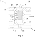
- Figure 2 shows an alternative embodiment in which a light source 88 in the form of a light-emitting diode is arranged on the circuit board 9 instead of the photocell 8.
- a light signal generated by the light-emitting diode for example maintenance requirements, error messages, etc., can be detected from the housing environment 15 through the translucent sealing plug 2.
- different light colors and light frequencies can be used for the light source.
- a photocell 8 and a light source 88 are provided, for example for commands entered via the lamp 28 to receive confirmation via the light source 88 or to output error messages.
- a code for the light timing to be entered with the lamp 28 and/or for the light signals emitted by the lamp 88 is either stuck on the housing wall 14 or is reproduced by the housing wall 14 itself. In the latter case, the code is in the plastic of the housing wall 14.
Landscapes
- Engineering & Computer Science (AREA)
- Microelectronics & Electronic Packaging (AREA)
- Mechanical Engineering (AREA)
- General Engineering & Computer Science (AREA)
- Casings For Electric Apparatus (AREA)
Description
- Die Erfindung betrifft ein Elektronikgehäuse zur Aufnahme von Elektronikbauteilen mit einer Dichtprüföffnung zur Durchführung einer Dichtheitsprüfung des Elektronikgehäuses.
- Aus dem Stand der Technik sind Elektronikgehäuse bekannt, welche eine hohe IP-Schutzart erfüllen und zur Sicherstellung ihrer ausreichenden Dichtheit einer Dichtheitsprüfung unterzogen werden. Hierfür weist das Elektronikgehäuse eine Dichtprüföffnung auf, über die beispielsweise ein Unterdruck oder Überdruck im Elektronikgehäuse erzeugt wird. Nach erfolgreicher Dichtheitsprüfung des Elektronikgehäuses wird die Dichtprüföffnung durch eine Dichtniete oder eine Dichtschraube verschlossen. Zur Sicherstellung der ausreichenden Abdichtung der Dichtprüföffnung muss eine weitere Dichtheitsprüfung der verschlossenen Dichtprüföffnung erfolgen, um auszuschließen, dass die Dichtschraube oder der Dichtniet falsch montiert wurde oder Materialfehler vorliegen. Das ist aufwändig und kostenintensiv.
- Die im Stand der Technik verwendeten Dichtschrauben weisen eine Unterkopfbeschichtung aus Kunststoff oder eine Mikroverkapselung auf. Die Dichtnieten sind teils mit speziellen Dichtbeschichtungen versehen. Zur Montage der Dichtniete ist ein Nietwerkzeug mit Zugkraftüberwachung einzusetzen, um eine festgelegte Position bzw. Verformung einzuhalten. Dabei kann jedoch eine Beschädigung des meist aus Kunststoff gefertigten Elektronikgehäuses nicht ausgeschlossen werden. Die Dichtschrauben werden mit festgelegtem Drehmoment und mithin ebenfalls mit einem Werkzeug verschraubt. Somit wird klar, dass die Befestigungsverfahren sehr genaue Prozesse und Gegenkonturen an der Dichtprüföffnung erfordern. Schwankungen im Montageprozess können dazu führen, dass die Dichtschraube nicht richtig abdichtet. Im Falle der Dichtniete und der Dichtschraube, meist aus metallischen Werkstoffen gebildet sind ist eine zuverlässige Abdichtung nach Temperaturwechseln, die im Falle eines Kunststoffgehäuses durch das Kriechen zu Setzungsverhalten führen und Mikrospalte zulassen, nicht mehr gewährleistet, was trotz geprüfter Dichtheit nach dem Verschließen im Betrieb zu einem Ausfall führen kann.
- Druckschriftlicher Stand der Technik aus dem vorliegenden technischen Gebiet ist in den Dokumenten
DE 10 2016 117 332 A1 ,EP 2 495 848 A2 undWO 2011/072888 A1 offenbart. - Der Erfindung liegt deshalb die Aufgabe zugrunde, ein gekapselt dichtes, insbesondere nach IP-Schutzart dichtes Elektronikgehäuse mit einer Abdichtung seiner Dichtprüföffnung zur Durchführung der Dichtheitsprüfung des Elektronikgehäuses bereitzustellen, welches dauerhafte temperaturunabhängige Abdichtung gewährleistet und eine zusätzliche Dichtheitsprüfung der Dichtprüföffnung selbst überflüssig macht.
- Diese Aufgabe wird durch die Merkmalskombination gemäß Patentanspruch 1 gelöst.
- Erfindungsgemäß wird ein Elektronikgehäuse zur Aufnahme von Elektronikbauteilen, insbesondere ein Ventilator-Elektronikgehäuse vorgeschlagen. Das Elektronikgehäuse ist gekapselt dicht, insbesondere nach einer IP-Schutzart ausgebildet und umfasst eine Dichtprüföffnung, die ausgebildet ist, eine Dichtheitsprüfung des gesamten Elektronikgehäuses durchzuführen. In der Dichtprüföffnung ist ein Dichtstopfen aus Silikon-Kautschuk angeordnet, der mehrere Dichtlippen aufweist, die an der Dichtprüföffnung dichtend anliegen und eine Mehrfachabdichtung bewirken.
- Der Dichtstopfen und die Geometrie der Dichtprüföffnung sind vorzugsweise mit rundem Querschnitt ausgeführt. Alternative kann der Querschnitt auch oval oder in Spezialfällen auch eckig gebildet sein. Die Geometrie des Dichtstopfens und der Dichtprüföffnung sind jedoch stets aufeinander abgestimmt.
- Mit dem Dichtstopfen aus Silikon-Kautschuk kann die Dichtprüföffnung prozesssicher abgedichtet und toleranzausgleichend bei thermischen Schwankungen verschlossen werden. Die Mehrzahl der Dichtlippen bietet eine ausreichende Sicherheit der Abdichtung der Dichtprüföffnung, so dass zusätzliche Dichtheitsprüfungen für die Dichtprüföffnung selbst entfallen können. Das Zusammenwirken von Dichtstopfen und Dichtprüföffnung richtet sich erfindungsgemäß ausschließlich auf diejenige Dichtprüföffnung, die dazu vorgesehen ist, die Dichtheitsprüfung des Elektronikgehäuses durchzuführen.
- In einer kostengünstigen und montagefreundlichen Ausführung ist vorgesehen, dass der Dichtstopfen einstückig ausgebildet ist.
- Ferner ist eine vorteilhafte Ausführung des Dichtstopfens dadurch gekennzeichnet, dass seine Dichtlippen in Reihe zueinander beabstandet angeordnet ausgebildet sind. Günstigerweise werden mindestens drei Dichtlippen vorgesehen, welche im bestimmungsgemäßen Gebrauch in der Dichtprüföffnung zur Anlage gebracht werden und eine Dreifachabdichtung gewährleisten.
- Das Elektronikgehäuse erfüllt vorteilhafterweise eine sehr hohe Dichtheitsanforderung nach IP-Schutzart, vorzugsweise nach der IP-Schutzart IP6(k)9(k), IP68, IP6x oder weitere mögliche Kombinationen unabhängig vom IP-Schutzgrad, bei denen ein gekapseltes, abgeschlossenes Elektronikgehäuse notwendig ist, um ungewollten Medieneintritt zu verhindern. Um beispielsweise Material- oder Montagefehler der an der Sicherstellung der Dichtheit beteiligten Komponenten festzustellen, ist eine Dichtheitsprüfung essentiell um sicher gewährleisten zu können, dass keine Undichtheiten im Feldbetrieb auftreten. Umfasst sind auch Elektronikgehäuse, welche ein Druckausgleichselement aufweisen und dabei gleichwohl gekapselt sind, so dass sie wasser- und staubdicht, aber luftdurchlässig sind.
- Besonders günstig bei dem Elektronikgehäuse ist eine Ausführung, wonach der Dichtstopfen händisch und werkzeugfrei in der Dichtprüföffnung montierbar ist. Der Dichtstopfen aus Silikon-Kautschuk wird manuell in die Dichtprüföffnung eingedrückt, bis alle Dichtlippen an der Innenwandfläche der Dichtprüföffnung anliegen. Vorzugsweise gibt es in der Dichtprüföffnung eine festgelegte Position für den Dichtstopfen, beispielsweise eine Markierung, hinter welche der Dichtstopfen zu drücken ist. Zudem weist der Dichtstopfen vorzugsweise eine ebene Fläche auf, über welche er in die Dichtprüföffnung eindrückbar ist. Die ebene Fläche kann zudem einen bündigen Übergang in einer Ebene zwischen der Außenwandung des Elektronikgehäuses und dem Dichtstopfen herstellen.
- Bei größeren Stückzahlen wird allerdings vorzugsweise ein prozessüberwachtes, automatisiertes Montagesystem eingesetzt, welches sowohl das Einbringen des Dichtstopfens realisiert als auch dessen finale Position abfragt. Somit kann auf die zusätzliche Dichtheitsprüfung verzichtet werden.
- Als günstiges Silikon-Material für den Dichtstopfen hat sich in der Praxis MVQ erwiesen. Deshalb sieht eine bevorzugte Ausführung dieses Material, beispielsweise als MVQ50 vor.
- In einer erfindungsgemäßen Ausbildung ist das Elektronikgehäuse dadurch gekennzeichnet, dass der Dichtstopfen transluzent ausgebildet ist und Lichtsignale zwischen einem Gehäuseinneren und einer Gehäuseumgebung durch den Dichtstopfen übermittelbar sind. Über die Lichtsignale können Funktionen der Elektronik im Elektronikgehäuse gesteuert werden. In die mittels des Dichtstopfens abgedichtete Dichtprüföffnung ist somit eine weitere Funktion integrierbar, ohne dass zusätzliche Fenster in dem Elektronikgehäuse vorzusehen wären.
- Eine günstige Ausführung des Elektronikgehäuses sieht dabei vor, dass angrenzend zu der Dichtprüföffnung ein Elektronikbauteil, insbesondere eine Leiterplatte, mit einer Photozelle in dem Gehäuseinneren des Elektronikgehäuses angeordnet ist, wobei die Photozelle der Dichtprüföffnung derart zugeordnet positioniert ist, dass ein Lichtsignal von der Gehäuseumgebung durch den Dichtstopfen auf die Photozelle übertragbar ist. Die Photozelle dient dann als Empfänger zur Umsetzung der z.B. getakteten Lichtsignale, welche eine Kommunikation beispielsweise des Kundendienstes mit der Elektronik im abgedichteten Elektronikgehäuse ermöglicht. Auch ist eine Programmierung, eine Programmauswahl oder Ventilatorkodierung der Elektronik über die Lichtsignale möglich. Anstelle einer Photozelle kann jedes Bauteil verwendet werden, das Lichtsignale bzw. optische Signale verarbeiten oder zumindest weiterleiten kann.
- Eine weitere Ausführungsform des Elektronikgehäuses ist dadurch gekennzeichnet, dass angrenzend zu der Dichtprüföffnung ein Elektronikbauteil, insbesondere eine Leiterplatte, mit einer Lichtquelle in dem Gehäuseinneren des Elektronikgehäuses angeordnet ist, wobei ein von der Lichtquelle ausgesendetes Licht durch den Dichtstopfen aus der Gehäuseumgebung erfassbar ist. Die Lichtquelle ist vorzugsweise als Leuchtdiode ausgebildet. Es können somit von der Elektronik über die Leuchtdiode Informationen visuell an die Gehäuseumgebung abgegeben und beispielsweise Störungen oder Programminformationen anhand eines Lichtsignals erfasst werden.
- Eine Weiterbildung sieht zudem vor, einen Code auf dem Elektronikgehäuse aufzubringen, z.B. per Plakette oder Aufkleber, der das auf die Photozelle zu übertragende Lichtsignal in einen Befehl oder das von der Leuchtquelle ausgesendete Lichtsignal in einen Bedeutungsinhalt übersetzt. Alternativ kann der Code auch durch die Gehäusewandung des Elektronikgehäuses selbst widergegeben werden und ist somit beispielsweise in den Kunststoff eingraviert oder eingepresst.
- Andere vorteilhafte Weiterbildungen der Erfindung sind in den Unteransprüchen gekennzeichnet bzw. werden nachstehend zusammen mit der Beschreibung der bevorzugten Ausführung der Erfindung anhand der Figuren näher dargestellt. Es zeigen:
- Fig. 1
- ein erstes Ausführungsbeispiel eines Elektronikgehäuses,
- Fig. 2
- ein zweites Ausführungsbeispiel eines Elektronikgehäuses.
- Die Figuren sind beispielhaft schematisch, die gezeichneten Merkmale sind jedoch Bestandteil der Offenbarung.
- In den
Figuren 1 und2 sind zwei Ausführungsbeispiele eines Elektronikgehäuses 1 dargestellt. Da die wesentlichen Merkmale übereinstimmen, werden beiden Figuren zunächst zusammen beschrieben, im Anschluss werden die Unterschiede dargestellt. - Das Elektronikgehäuse 1 ist ein an einem Ventilator verwendetes Gehäuse, in dem die in der Technik bekannten, zur Regelung des Antriebsmotors verwendeten Elektronikbauteile aufgenommen sind. Beispielhaft ist hierfür eine Leiterplatte 9 mit einem angedeuteten Elektronikbauteil 4 gezeigt. Das Elektronikgehäuse 1 ist mit einer Gehäusewand 14 vorzugsweise einstückig aus Kunststoff gefertigt und dicht nach z.B. der IP-Schutzart IP6k9k. Zur Dichtheitsprüfung ist die Dichtprüföffnung 5 in dem Elektronikgehäuse 1 vorgesehen, welche durch einen sich ins Gehäuseinnere 14 erstreckenden, gewindefreien Rohrabschnitt 7 gebildet ist. In der Dichtprüföffnung 5 ist der einstückige Dichtstopfen 2 aus Silikon-Kautschuk, vorzugsweise aus MVQ50, eingedrückt und liegt mit seinen drei in Reihe angeordneten und jeweils axial beabstandeten Dichtlippen 3, 3', 3" an der Innenwandfläche des Rohrabschnitts 7 an. Der Einlass in die Dichtprüföffnung 5 weist Schrägen 18 auf, welche eine gerade Zuführung des Dichtstopfens 2 ermöglichen und ein Verkanten vermeiden. Am freien Ende 12 ist der Rohrabschnitt 7 der Dichtprüföffnung 5 eingezogen ausgebildet, so dass sich die Querschnittsfläche des Innenrohres verringert. Somit ist ein zu tiefes Einstecken des Dichtstopfens 2 ausgeschlossen. Die zwei Dichtlippen 3', 3" weisen eine identische geometrische Dreiecksform auf, sind jedoch geometrisch unterschiedlich zur Dichtlippe 3, welche als geradlinig nach radial außen verlaufender Steg gebildet ist. Die drei Dichtlippen 3, 3', 3" erzeugen eine Mehrfachabdichtung und bieten eine hohe Sicherheit, so dass eine zusätzliche Dichtheitsprüfung nach dem Eindrücken des Dichtstopfens 2 nicht nötig ist. An die letzte Dichtlippe 3 angrenzend weist der Dichtstopfen 2 einen freien Schenkel 11 auf, dessen freies Ende mit einer Aufdickung 13 nach radial außen versehen ist.
- Der Dichtstopfen 2 weist eine zur Gehäuseumgebung 15 weisende flache und ebene Oberfläche auf. Diese Oberfläche ist geeignet, um mit dem Finger den Dichtstopfen 2 in die Dichtprüföffnung 5 zu drücken, ohne dass es eines Werkzeugs bedarf. Bei einer Positionierung beispielsweise durch ein automatisiertes Werkzeug kann die ebene Oberfläche ebenfalls für eine optimale Positionierung des Dichtstopfens 2 genutzt werden. Der Dichtstopfen 2 ist zudem transluzent ausgebildet.
- Gemäß der Ausführung in
Figur 1 ist gezeigt, dass mit einer in der Gehäuseumgebung 15 positionierten oder beispielsweise einem Techniker gehaltenen Lampe 28 durch den Dichtstopfen 2 hindurch auf eine auf der Leiterplatte 9 der Dichtprüföffnung 5 zugeordnet positionierte Photozelle 8 geleuchtet werden kann. Die flache ebene Oberfläche des Dichtstopfens 2 ist hierbei besonders vorteilhaft, um die Lichtstrahlen mit wenig Streuung weiterzuleiten. Über spezielle Lichttaktungen der Lichtsignale können somit beispielsweise Befehle über die Photozelle 8 an die Elektronik im Gehäuseinneren 14 übertragen werden. Der Dichtstopfen 2 funktioniert somit neben seiner Aufgabe zur Abdichtung der Dichtprüföffnung 5 zudem als Fenster zwischen dem Gehäuseinneren 14 und der Gehäuseumgebung 15. -
Figur 2 zeigt eine alternative Ausführung, bei der anstelle der Photozelle 8 auf der Leiterplatte 9 eine Lichtquelle 88 in Form einer Leuchtdiode angeordnet ist. Ein von der Leuchtdiode erzeugtes Lichtsignal, z.B. Wartungsbedarf, Fehlermeldung, etc. kann aus der Gehäuseumgebung 15 durch den transluzenten Dichtstopfen 2 erfasst werden. Hierfür können bei der Lichtquelle unterschiedliche Lichtfarben und Leuchtfrequenzen eingesetzt werden. - Natürlich ist zudem auch eine Ausführung möglich und von der Offenbarung umfasst, bei der sowohl eine Photozelle 8 als auch eine Lichtquelle 88 vorgesehen sind, um beispielsweise über die Lampe 28 eingegebene Befehle über die Lichtquelle 88 bestätigt zu erhalten oder Fehlermeldungen auszugeben.
- Ein Code für die mit der Lampe 28 einzugebende Lichttaktung und/oder für die durch das Leuchtmittel 88 ausgegebenen Lichtsignale ist entweder auf der Gehäusewandung 14 aufgeklebt oder wird durch die Gehäusewandung 14 selbst wiedergegeben. Bei letzterer ist der Code im Kunststoff der Gehäusewandung 14.
Claims (10)
- Elektronikgehäuse (1) zur Aufnahme von Elektronikbauteilen (4), insbesondere Ventilator-Elektronikgehäuse, wobei das Elektronikgehäuse (1) dicht gekapselt, insbesondere nach einer IP-Schutzart ausgebildet ist und eine Dichtprüföffnung (5) umfasst, die ausgebildet ist, eine Dichtheitsprüfung des gesamten Elektronikgehäuses (1) durchzuführen, wobei in der Dichtprüföffnung (5) ein Dichtstopfen (2) aus Silikon-Kautschuk angeordnet ist, der mehrere Dichtlippen (3, 3', 3") aufweist, die an der Dichtprüföffnung (5) dichtend anliegen und eine Mehrfachabdichtung bewirken, wobei, der Dichtstopfen (2) transluzent ausgebildet ist und Lichtsignale zwischen einem Gehäuseinneren (14) und einer Gehäuseumgebung (15) durch den Dichtstopfen (2) übermittelbar sind.
- Elektronikgehäuse nach Anspruch 1, dadurch gekennzeichnet, dass der Dichtstopfen (2) einstückig ausgebildet ist.
- Elektronikgehäuse nach Anspruch 1 oder 2, dadurch gekennzeichnet, dass die Dichtlippen (3, 3', 3") des Dichtstopfens (2) in Reihe zueinander beabstandet angeordnet ausgebildet sind und eine unterschiedliche geometrische Form aufweisen.
- Elektronikgehäuse nach einem der vorigen Ansprüche, dadurch gekennzeichnet, dass der Dichtstopfen (2) ausgebildet ist, händisch und werkzeugfrei in der Dichtprüföffnung (5) montiert zu werden.
- Elektronikgehäuse nach einem der vorigen Ansprüche, dadurch gekennzeichnet, dass der Dichtstopfen (2) aus Silikon-Kautschuk MVQ gebildet ist.
- Elektronikgehäuse nach einem der vorigen Ansprüche, dadurch gekennzeichnet, dass angrenzend zu der Dichtprüföffnung (5) ein Elektronikbauteil mit einer Photozelle (8) in dem Gehäuseinneren (14) des Elektronikgehäuses (1) angeordnet ist, wobei die Photozelle (8) der Dichtprüföffnung (5) zugeordnet positioniert ist, dass ein Lichtsignal von der Gehäuseumgebung (15) durch den Dichtstopfen (2) auf die Photozelle (8) übertragbar ist.
- Elektronikgehäuse nach einem der vorigen Ansprüche, dadurch gekennzeichnet, dass angrenzend zu der Dichtprüföffnung (5) ein Elektronikbauteil mit einer Lichtquelle (28) in dem Gehäuseinneren (14) des Elektronikgehäuses (1) angeordnet ist, wobei ein von der Lichtquelle (88) ausgesendetes Lichtsignal durch den Dichtstopfen (2) aus der Gehäuseumgebung (15) erfassbar ist.
- Elektronikgehäuse nach dem vorigen Anspruch, dadurch gekennzeichnet, dass die Lichtquelle (88) als Leuchtdiode ausgebildet ist.
- Elektronikgehäuse nach einem der vorigen Ansprüche 6 - 8, dadurch gekennzeichnet, dass auf dem Elektronikgehäuse (1) ein Code aufgebracht ist, der das auf die Photozelle zu übertragende Lichtsignal in einen Befehl oder das von der Leuchtquelle ausgesendete Lichtsignal in einen Bedeutungsinhalt übersetzt.
- Elektronikgehäuse nach dem vorigen Anspruch, dadurch gekennzeichnet, dass der Code durch eine Gehäusewandung (14) des Elektronikgehäuses wiedergegeben ist.
Applications Claiming Priority (1)
| Application Number | Priority Date | Filing Date | Title |
|---|---|---|---|
| DE102020107247.3A DE102020107247A1 (de) | 2020-03-17 | 2020-03-17 | Elektronikgehäuse mit Dichtprüföffnung und Dichtstopfen |
Publications (2)
| Publication Number | Publication Date |
|---|---|
| EP3883354A1 EP3883354A1 (de) | 2021-09-22 |
| EP3883354B1 true EP3883354B1 (de) | 2023-11-01 |
Family
ID=74494793
Family Applications (1)
| Application Number | Title | Priority Date | Filing Date |
|---|---|---|---|
| EP21154551.2A Active EP3883354B1 (de) | 2020-03-17 | 2021-02-01 | Elektronikgehäuse mit dichtprüföffnung und dichtstopfen |
Country Status (2)
| Country | Link |
|---|---|
| EP (1) | EP3883354B1 (de) |
| DE (1) | DE102020107247A1 (de) |
Families Citing this family (1)
| Publication number | Priority date | Publication date | Assignee | Title |
|---|---|---|---|---|
| DE102023115362A1 (de) * | 2023-06-13 | 2024-12-19 | Brose Antriebstechnik GmbH & Co. Kommanditgesellschaft, Berlin | Steckverbinderbauteil für ein Antriebsgehäuse, Antriebsgehäuse und Prüfverfahren |
Family Cites Families (4)
| Publication number | Priority date | Publication date | Assignee | Title |
|---|---|---|---|---|
| ITBO20060339A1 (it) * | 2006-05-08 | 2007-11-09 | Spal Automotive Srl | Metodo per assemblare un motore elettrico e motore ottenuto con tale metodo |
| DE102008014688B4 (de) | 2008-03-18 | 2013-02-21 | Rehau Ag + Co. | Ölwanne sowie Verschlusselement für eine Ölwanne |
| DE202009019185U1 (de) * | 2009-12-17 | 2017-12-01 | Ebm-Papst Landshut Gmbh | Dichtung einer Gebläseanordnung |
| DE102016117332A1 (de) | 2016-09-15 | 2018-03-15 | Knorr-Bremse Systeme für Nutzfahrzeuge GmbH | Gehäuse mit Entlüftung für ein Steuergerät |
-
2020
- 2020-03-17 DE DE102020107247.3A patent/DE102020107247A1/de not_active Withdrawn
-
2021
- 2021-02-01 EP EP21154551.2A patent/EP3883354B1/de active Active
Also Published As
| Publication number | Publication date |
|---|---|
| DE102020107247A1 (de) | 2021-09-23 |
| EP3883354A1 (de) | 2021-09-22 |
Similar Documents
| Publication | Publication Date | Title |
|---|---|---|
| DE69710005T2 (de) | Verbundglasscheibe mit Detektor | |
| DE102005059538B4 (de) | Scharnier-Sensor | |
| EP3380814B1 (de) | Explosionsgeschütztes gehäuse für mittel zum senden und empfangen elektromagnetischer strahlung | |
| WO2008110235A1 (de) | Kabelverschraubung mit einer gegenhülse oder überwurfmutter | |
| EP2126519B1 (de) | Unfallsensor | |
| DE112015000086T5 (de) | Raddrehzahlsensor und Herstellungsverfahren dafür | |
| DE102014210297A1 (de) | Demontageverfahren für eine Gasturbine | |
| DE102007022192A1 (de) | Getriebegehäuse für eine elektrische Antriebseinheit eines Scheibenwischers | |
| EP3261200A1 (de) | Sensorsystem für schaltanlagen | |
| DE102018124845A1 (de) | Sensoreinheit | |
| EP1750109A1 (de) | Drehmomentsensor und Verfahren zu dessen Herstellung | |
| EP3883354A1 (de) | Elektronikgehäuse mit dichtprüföffnung und dichtstopfen | |
| EP2292959A2 (de) | Ansteuermodul | |
| DE202015007517U1 (de) | Flanschbaugruppe zur Befestigung eines Kabels an einer Wand mit einer Durchführung | |
| DE19743615A1 (de) | Airbagbaueinheit | |
| DE4339302C2 (de) | Farbwechselblock mit Leckageindikatoren | |
| DE102021204971A1 (de) | Adaptionseinrichtung zur Ankopplung mindestens eines Sensors an eine Schlauchmantelwand eines Schlauchs zur Fluidvermessung sowie Sensorvorrichtung mit einer derartigen Adaptionseinrichtung | |
| DE102007046465A1 (de) | Vorrichtung zur Detektion von Leckagen an Leitungssystemen | |
| DE102016000981A1 (de) | Prüfvorrichtung zum Überprüfen einer Verbindungsanordnung | |
| EP0883214B1 (de) | Flüssigkeitsdichte Steckverbinder | |
| EP2167348B1 (de) | Anzeigevorrichtung, insbesondere fahrzeuganzeigevorrichtung, mit einem helligkeitssensor | |
| DE102009008968A1 (de) | Feuchtesensor | |
| DE10205810B4 (de) | Vorrichtung zum Öffnen und Schliessen einer Öffnung mit einer Befestigungsvorrichtung für einen Lichtwellenleiter | |
| EP3396246A1 (de) | Messstellen-system | |
| DE102006050801B4 (de) | Mechatronische Baugruppe |
Legal Events
| Date | Code | Title | Description |
|---|---|---|---|
| PUAI | Public reference made under article 153(3) epc to a published international application that has entered the european phase |
Free format text: ORIGINAL CODE: 0009012 |
|
| STAA | Information on the status of an ep patent application or granted ep patent |
Free format text: STATUS: THE APPLICATION HAS BEEN PUBLISHED |
|
| AK | Designated contracting states |
Kind code of ref document: A1 Designated state(s): AL AT BE BG CH CY CZ DE DK EE ES FI FR GB GR HR HU IE IS IT LI LT LU LV MC MK MT NL NO PL PT RO RS SE SI SK SM TR |
|
| STAA | Information on the status of an ep patent application or granted ep patent |
Free format text: STATUS: REQUEST FOR EXAMINATION WAS MADE |
|
| 17P | Request for examination filed |
Effective date: 20220228 |
|
| RBV | Designated contracting states (corrected) |
Designated state(s): AL AT BE BG CH CY CZ DE DK EE ES FI FR GB GR HR HU IE IS IT LI LT LU LV MC MK MT NL NO PL PT RO RS SE SI SK SM TR |
|
| GRAP | Despatch of communication of intention to grant a patent |
Free format text: ORIGINAL CODE: EPIDOSNIGR1 |
|
| STAA | Information on the status of an ep patent application or granted ep patent |
Free format text: STATUS: GRANT OF PATENT IS INTENDED |
|
| INTG | Intention to grant announced |
Effective date: 20230614 |
|
| GRAS | Grant fee paid |
Free format text: ORIGINAL CODE: EPIDOSNIGR3 |
|
| GRAA | (expected) grant |
Free format text: ORIGINAL CODE: 0009210 |
|
| STAA | Information on the status of an ep patent application or granted ep patent |
Free format text: STATUS: THE PATENT HAS BEEN GRANTED |
|
| AK | Designated contracting states |
Kind code of ref document: B1 Designated state(s): AL AT BE BG CH CY CZ DE DK EE ES FI FR GB GR HR HU IE IS IT LI LT LU LV MC MK MT NL NO PL PT RO RS SE SI SK SM TR |
|
| P01 | Opt-out of the competence of the unified patent court (upc) registered |
Effective date: 20230927 |
|
| REG | Reference to a national code |
Ref country code: GB Ref legal event code: FG4D Free format text: NOT ENGLISH |
|
| REG | Reference to a national code |
Ref country code: CH Ref legal event code: EP |
|
| REG | Reference to a national code |
Ref country code: DE Ref legal event code: R096 Ref document number: 502021001815 Country of ref document: DE |
|
| REG | Reference to a national code |
Ref country code: IE Ref legal event code: FG4D Free format text: LANGUAGE OF EP DOCUMENT: GERMAN |
|
| REG | Reference to a national code |
Ref country code: NL Ref legal event code: FP |
|
| REG | Reference to a national code |
Ref country code: LT Ref legal event code: MG9D |
|
| PG25 | Lapsed in a contracting state [announced via postgrant information from national office to epo] |
Ref country code: GR Free format text: LAPSE BECAUSE OF FAILURE TO SUBMIT A TRANSLATION OF THE DESCRIPTION OR TO PAY THE FEE WITHIN THE PRESCRIBED TIME-LIMIT Effective date: 20240202 |
|
| PG25 | Lapsed in a contracting state [announced via postgrant information from national office to epo] |
Ref country code: IS Free format text: LAPSE BECAUSE OF FAILURE TO SUBMIT A TRANSLATION OF THE DESCRIPTION OR TO PAY THE FEE WITHIN THE PRESCRIBED TIME-LIMIT Effective date: 20240301 |
|
| PG25 | Lapsed in a contracting state [announced via postgrant information from national office to epo] |
Ref country code: LT Free format text: LAPSE BECAUSE OF FAILURE TO SUBMIT A TRANSLATION OF THE DESCRIPTION OR TO PAY THE FEE WITHIN THE PRESCRIBED TIME-LIMIT Effective date: 20231101 |
|
| PG25 | Lapsed in a contracting state [announced via postgrant information from national office to epo] |
Ref country code: ES Free format text: LAPSE BECAUSE OF FAILURE TO SUBMIT A TRANSLATION OF THE DESCRIPTION OR TO PAY THE FEE WITHIN THE PRESCRIBED TIME-LIMIT Effective date: 20231101 |
|
| PG25 | Lapsed in a contracting state [announced via postgrant information from national office to epo] |
Ref country code: LT Free format text: LAPSE BECAUSE OF FAILURE TO SUBMIT A TRANSLATION OF THE DESCRIPTION OR TO PAY THE FEE WITHIN THE PRESCRIBED TIME-LIMIT Effective date: 20231101 Ref country code: IS Free format text: LAPSE BECAUSE OF FAILURE TO SUBMIT A TRANSLATION OF THE DESCRIPTION OR TO PAY THE FEE WITHIN THE PRESCRIBED TIME-LIMIT Effective date: 20240301 Ref country code: GR Free format text: LAPSE BECAUSE OF FAILURE TO SUBMIT A TRANSLATION OF THE DESCRIPTION OR TO PAY THE FEE WITHIN THE PRESCRIBED TIME-LIMIT Effective date: 20240202 Ref country code: ES Free format text: LAPSE BECAUSE OF FAILURE TO SUBMIT A TRANSLATION OF THE DESCRIPTION OR TO PAY THE FEE WITHIN THE PRESCRIBED TIME-LIMIT Effective date: 20231101 Ref country code: BG Free format text: LAPSE BECAUSE OF FAILURE TO SUBMIT A TRANSLATION OF THE DESCRIPTION OR TO PAY THE FEE WITHIN THE PRESCRIBED TIME-LIMIT Effective date: 20240201 Ref country code: PT Free format text: LAPSE BECAUSE OF FAILURE TO SUBMIT A TRANSLATION OF THE DESCRIPTION OR TO PAY THE FEE WITHIN THE PRESCRIBED TIME-LIMIT Effective date: 20240301 |
|
| PG25 | Lapsed in a contracting state [announced via postgrant information from national office to epo] |
Ref country code: SE Free format text: LAPSE BECAUSE OF FAILURE TO SUBMIT A TRANSLATION OF THE DESCRIPTION OR TO PAY THE FEE WITHIN THE PRESCRIBED TIME-LIMIT Effective date: 20231101 Ref country code: RS Free format text: LAPSE BECAUSE OF FAILURE TO SUBMIT A TRANSLATION OF THE DESCRIPTION OR TO PAY THE FEE WITHIN THE PRESCRIBED TIME-LIMIT Effective date: 20231101 Ref country code: PL Free format text: LAPSE BECAUSE OF FAILURE TO SUBMIT A TRANSLATION OF THE DESCRIPTION OR TO PAY THE FEE WITHIN THE PRESCRIBED TIME-LIMIT Effective date: 20231101 Ref country code: NO Free format text: LAPSE BECAUSE OF FAILURE TO SUBMIT A TRANSLATION OF THE DESCRIPTION OR TO PAY THE FEE WITHIN THE PRESCRIBED TIME-LIMIT Effective date: 20240201 Ref country code: LV Free format text: LAPSE BECAUSE OF FAILURE TO SUBMIT A TRANSLATION OF THE DESCRIPTION OR TO PAY THE FEE WITHIN THE PRESCRIBED TIME-LIMIT Effective date: 20231101 Ref country code: HR Free format text: LAPSE BECAUSE OF FAILURE TO SUBMIT A TRANSLATION OF THE DESCRIPTION OR TO PAY THE FEE WITHIN THE PRESCRIBED TIME-LIMIT Effective date: 20231101 |
|
| PG25 | Lapsed in a contracting state [announced via postgrant information from national office to epo] |
Ref country code: DK Free format text: LAPSE BECAUSE OF FAILURE TO SUBMIT A TRANSLATION OF THE DESCRIPTION OR TO PAY THE FEE WITHIN THE PRESCRIBED TIME-LIMIT Effective date: 20231101 |
|
| PG25 | Lapsed in a contracting state [announced via postgrant information from national office to epo] |
Ref country code: CZ Free format text: LAPSE BECAUSE OF FAILURE TO SUBMIT A TRANSLATION OF THE DESCRIPTION OR TO PAY THE FEE WITHIN THE PRESCRIBED TIME-LIMIT Effective date: 20231101 |
|
| PG25 | Lapsed in a contracting state [announced via postgrant information from national office to epo] |
Ref country code: SK Free format text: LAPSE BECAUSE OF FAILURE TO SUBMIT A TRANSLATION OF THE DESCRIPTION OR TO PAY THE FEE WITHIN THE PRESCRIBED TIME-LIMIT Effective date: 20231101 |
|
| PG25 | Lapsed in a contracting state [announced via postgrant information from national office to epo] |
Ref country code: SM Free format text: LAPSE BECAUSE OF FAILURE TO SUBMIT A TRANSLATION OF THE DESCRIPTION OR TO PAY THE FEE WITHIN THE PRESCRIBED TIME-LIMIT Effective date: 20231101 Ref country code: SK Free format text: LAPSE BECAUSE OF FAILURE TO SUBMIT A TRANSLATION OF THE DESCRIPTION OR TO PAY THE FEE WITHIN THE PRESCRIBED TIME-LIMIT Effective date: 20231101 Ref country code: IT Free format text: LAPSE BECAUSE OF FAILURE TO SUBMIT A TRANSLATION OF THE DESCRIPTION OR TO PAY THE FEE WITHIN THE PRESCRIBED TIME-LIMIT Effective date: 20231101 Ref country code: EE Free format text: LAPSE BECAUSE OF FAILURE TO SUBMIT A TRANSLATION OF THE DESCRIPTION OR TO PAY THE FEE WITHIN THE PRESCRIBED TIME-LIMIT Effective date: 20231101 Ref country code: DK Free format text: LAPSE BECAUSE OF FAILURE TO SUBMIT A TRANSLATION OF THE DESCRIPTION OR TO PAY THE FEE WITHIN THE PRESCRIBED TIME-LIMIT Effective date: 20231101 Ref country code: CZ Free format text: LAPSE BECAUSE OF FAILURE TO SUBMIT A TRANSLATION OF THE DESCRIPTION OR TO PAY THE FEE WITHIN THE PRESCRIBED TIME-LIMIT Effective date: 20231101 |
|
| REG | Reference to a national code |
Ref country code: DE Ref legal event code: R097 Ref document number: 502021001815 Country of ref document: DE |
|
| PLBE | No opposition filed within time limit |
Free format text: ORIGINAL CODE: 0009261 |
|
| STAA | Information on the status of an ep patent application or granted ep patent |
Free format text: STATUS: NO OPPOSITION FILED WITHIN TIME LIMIT |
|
| PG25 | Lapsed in a contracting state [announced via postgrant information from national office to epo] |
Ref country code: MC Free format text: LAPSE BECAUSE OF FAILURE TO SUBMIT A TRANSLATION OF THE DESCRIPTION OR TO PAY THE FEE WITHIN THE PRESCRIBED TIME-LIMIT Effective date: 20231101 |
|
| REG | Reference to a national code |
Ref country code: CH Ref legal event code: PL |
|
| 26N | No opposition filed |
Effective date: 20240802 |
|
| PG25 | Lapsed in a contracting state [announced via postgrant information from national office to epo] |
Ref country code: LU Free format text: LAPSE BECAUSE OF NON-PAYMENT OF DUE FEES Effective date: 20240201 |
|
| PG25 | Lapsed in a contracting state [announced via postgrant information from national office to epo] |
Ref country code: CH Free format text: LAPSE BECAUSE OF NON-PAYMENT OF DUE FEES Effective date: 20240229 |
|
| PG25 | Lapsed in a contracting state [announced via postgrant information from national office to epo] |
Ref country code: SI Free format text: LAPSE BECAUSE OF FAILURE TO SUBMIT A TRANSLATION OF THE DESCRIPTION OR TO PAY THE FEE WITHIN THE PRESCRIBED TIME-LIMIT Effective date: 20231101 |
|
| PG25 | Lapsed in a contracting state [announced via postgrant information from national office to epo] |
Ref country code: SI Free format text: LAPSE BECAUSE OF FAILURE TO SUBMIT A TRANSLATION OF THE DESCRIPTION OR TO PAY THE FEE WITHIN THE PRESCRIBED TIME-LIMIT Effective date: 20231101 Ref country code: LU Free format text: LAPSE BECAUSE OF NON-PAYMENT OF DUE FEES Effective date: 20240201 Ref country code: CH Free format text: LAPSE BECAUSE OF NON-PAYMENT OF DUE FEES Effective date: 20240229 |
|
| REG | Reference to a national code |
Ref country code: BE Ref legal event code: MM Effective date: 20240229 |
|
| PG25 | Lapsed in a contracting state [announced via postgrant information from national office to epo] |
Ref country code: BE Free format text: LAPSE BECAUSE OF NON-PAYMENT OF DUE FEES Effective date: 20240229 |
|
| PG25 | Lapsed in a contracting state [announced via postgrant information from national office to epo] |
Ref country code: IE Free format text: LAPSE BECAUSE OF NON-PAYMENT OF DUE FEES Effective date: 20240201 |
|
| PG25 | Lapsed in a contracting state [announced via postgrant information from national office to epo] |
Ref country code: IE Free format text: LAPSE BECAUSE OF NON-PAYMENT OF DUE FEES Effective date: 20240201 Ref country code: BE Free format text: LAPSE BECAUSE OF NON-PAYMENT OF DUE FEES Effective date: 20240229 |
|
| PGFP | Annual fee paid to national office [announced via postgrant information from national office to epo] |
Ref country code: NL Payment date: 20250220 Year of fee payment: 5 |
|
| PGFP | Annual fee paid to national office [announced via postgrant information from national office to epo] |
Ref country code: AT Payment date: 20250417 Year of fee payment: 5 |
|
| PG25 | Lapsed in a contracting state [announced via postgrant information from national office to epo] |
Ref country code: RO Free format text: LAPSE BECAUSE OF FAILURE TO SUBMIT A TRANSLATION OF THE DESCRIPTION OR TO PAY THE FEE WITHIN THE PRESCRIBED TIME-LIMIT Effective date: 20231101 |
|
| PG25 | Lapsed in a contracting state [announced via postgrant information from national office to epo] |
Ref country code: CY Free format text: LAPSE BECAUSE OF FAILURE TO SUBMIT A TRANSLATION OF THE DESCRIPTION OR TO PAY THE FEE WITHIN THE PRESCRIBED TIME-LIMIT; INVALID AB INITIO Effective date: 20210201 |
|
| PG25 | Lapsed in a contracting state [announced via postgrant information from national office to epo] |
Ref country code: HU Free format text: LAPSE BECAUSE OF FAILURE TO SUBMIT A TRANSLATION OF THE DESCRIPTION OR TO PAY THE FEE WITHIN THE PRESCRIBED TIME-LIMIT; INVALID AB INITIO Effective date: 20210201 |
|
| PG25 | Lapsed in a contracting state [announced via postgrant information from national office to epo] |
Ref country code: FI Free format text: LAPSE BECAUSE OF FAILURE TO SUBMIT A TRANSLATION OF THE DESCRIPTION OR TO PAY THE FEE WITHIN THE PRESCRIBED TIME-LIMIT Effective date: 20231101 |
|
| PG25 | Lapsed in a contracting state [announced via postgrant information from national office to epo] |
Ref country code: TR Free format text: LAPSE BECAUSE OF FAILURE TO SUBMIT A TRANSLATION OF THE DESCRIPTION OR TO PAY THE FEE WITHIN THE PRESCRIBED TIME-LIMIT Effective date: 20231101 |
|
| PGFP | Annual fee paid to national office [announced via postgrant information from national office to epo] |
Ref country code: GB Payment date: 20260219 Year of fee payment: 6 |
|
| PGFP | Annual fee paid to national office [announced via postgrant information from national office to epo] |
Ref country code: DE Payment date: 20260217 Year of fee payment: 6 |
|
| PGFP | Annual fee paid to national office [announced via postgrant information from national office to epo] |
Ref country code: FR Payment date: 20260219 Year of fee payment: 6 |