EP2495848A2 - Electric motor - Google Patents
Electric motor Download PDFInfo
- Publication number
- EP2495848A2 EP2495848A2 EP12169842A EP12169842A EP2495848A2 EP 2495848 A2 EP2495848 A2 EP 2495848A2 EP 12169842 A EP12169842 A EP 12169842A EP 12169842 A EP12169842 A EP 12169842A EP 2495848 A2 EP2495848 A2 EP 2495848A2
- Authority
- EP
- European Patent Office
- Prior art keywords
- lid
- bearing
- casing
- cavity
- motor
- Prior art date
- Legal status (The legal status is an assumption and is not a legal conclusion. Google has not performed a legal analysis and makes no representation as to the accuracy of the status listed.)
- Withdrawn
Links
- 238000007789 sealing Methods 0.000 claims abstract 3
- 239000000463 material Substances 0.000 claims description 6
- 229920001296 polysiloxane Polymers 0.000 claims description 2
- 238000003825 pressing Methods 0.000 claims description 2
- 238000012360 testing method Methods 0.000 description 17
- 239000003566 sealing material Substances 0.000 description 14
- 238000000034 method Methods 0.000 description 9
- 239000012530 fluid Substances 0.000 description 6
- 238000000465 moulding Methods 0.000 description 5
- 239000000853 adhesive Substances 0.000 description 4
- 230000001070 adhesive effect Effects 0.000 description 4
- 239000003795 chemical substances by application Substances 0.000 description 3
- 230000008595 infiltration Effects 0.000 description 3
- 238000001764 infiltration Methods 0.000 description 3
- 239000007788 liquid Substances 0.000 description 3
- 238000004891 communication Methods 0.000 description 2
- 238000010586 diagram Methods 0.000 description 2
- 238000007654 immersion Methods 0.000 description 2
- 229920002635 polyurethane Polymers 0.000 description 2
- 239000004814 polyurethane Substances 0.000 description 2
- 229920005830 Polyurethane Foam Polymers 0.000 description 1
- 230000015572 biosynthetic process Effects 0.000 description 1
- 238000007664 blowing Methods 0.000 description 1
- 238000013016 damping Methods 0.000 description 1
- 230000001419 dependent effect Effects 0.000 description 1
- 230000007613 environmental effect Effects 0.000 description 1
- 239000006260 foam Substances 0.000 description 1
- 238000004519 manufacturing process Methods 0.000 description 1
- 239000002184 metal Substances 0.000 description 1
- 239000011496 polyurethane foam Substances 0.000 description 1
- 238000005476 soldering Methods 0.000 description 1
- XLYOFNOQVPJJNP-UHFFFAOYSA-N water Substances O XLYOFNOQVPJJNP-UHFFFAOYSA-N 0.000 description 1
Images



Classifications
-
- H—ELECTRICITY
- H02—GENERATION; CONVERSION OR DISTRIBUTION OF ELECTRIC POWER
- H02K—DYNAMO-ELECTRIC MACHINES
- H02K15/00—Processes or apparatus specially adapted for manufacturing, assembling, maintaining or repairing of dynamo-electric machines
- H02K15/14—Casings; Enclosures; Supports
-
- H—ELECTRICITY
- H02—GENERATION; CONVERSION OR DISTRIBUTION OF ELECTRIC POWER
- H02K—DYNAMO-ELECTRIC MACHINES
- H02K5/00—Casings; Enclosures; Supports
- H02K5/04—Casings or enclosures characterised by the shape, form or construction thereof
- H02K5/10—Casings or enclosures characterised by the shape, form or construction thereof with arrangements for protection from ingress, e.g. water or fingers
-
- H—ELECTRICITY
- H02—GENERATION; CONVERSION OR DISTRIBUTION OF ELECTRIC POWER
- H02K—DYNAMO-ELECTRIC MACHINES
- H02K5/00—Casings; Enclosures; Supports
- H02K5/04—Casings or enclosures characterised by the shape, form or construction thereof
- H02K5/22—Auxiliary parts of casings not covered by groups H02K5/06-H02K5/20, e.g. shaped to form connection boxes or terminal boxes
- H02K5/225—Terminal boxes or connection arrangements
-
- Y—GENERAL TAGGING OF NEW TECHNOLOGICAL DEVELOPMENTS; GENERAL TAGGING OF CROSS-SECTIONAL TECHNOLOGIES SPANNING OVER SEVERAL SECTIONS OF THE IPC; TECHNICAL SUBJECTS COVERED BY FORMER USPC CROSS-REFERENCE ART COLLECTIONS [XRACs] AND DIGESTS
- Y10—TECHNICAL SUBJECTS COVERED BY FORMER USPC
- Y10T—TECHNICAL SUBJECTS COVERED BY FORMER US CLASSIFICATION
- Y10T29/00—Metal working
- Y10T29/49—Method of mechanical manufacture
- Y10T29/49002—Electrical device making
- Y10T29/49009—Dynamoelectric machine
-
- Y—GENERAL TAGGING OF NEW TECHNOLOGICAL DEVELOPMENTS; GENERAL TAGGING OF CROSS-SECTIONAL TECHNOLOGIES SPANNING OVER SEVERAL SECTIONS OF THE IPC; TECHNICAL SUBJECTS COVERED BY FORMER USPC CROSS-REFERENCE ART COLLECTIONS [XRACs] AND DIGESTS
- Y10—TECHNICAL SUBJECTS COVERED BY FORMER USPC
- Y10T—TECHNICAL SUBJECTS COVERED BY FORMER US CLASSIFICATION
- Y10T29/00—Metal working
- Y10T29/49—Method of mechanical manufacture
- Y10T29/49002—Electrical device making
- Y10T29/4902—Electromagnet, transformer or inductor
Definitions
- the present invention relates to an electric motor and in particular to a watertight electric motor.
- stator and the rotor in the casing To mount the stator and the rotor in the casing, the latter must be divided into at least two parts which can be assembled.
- the gasket between the two parts of the casing may not be perfectly positioned or effectively squashed to guarantee a suitable seal between the parts in contact.
- infiltrations may occur at the motor shaft supports, in particular where the motor shaft comes out of the casing for motor effectiveness.
- the main technical purpose of the present invention is to propose a method for assembling an electric motor and an electric motor obtained with this method which are free of the above-mentioned disadvantages.
- One aim of the present invention is to propose a method which allows an electric motor to be obtained with good hermetic properties.
- Another aim of the present invention is to propose a method for assembling an electric motor which is simple and inexpensive to implement.
- the numeral 1 denotes an electric motor assembled in accordance with the present invention.
- the motor 1 comprises means 8 for supporting the rotary unit 6 positioned inside the casing 2.
- the bearing 9 is locked in the cavity 9a preferably by means of caulking, as described in further detail below.
- the motor 1 also preferably comprises a gasket 21, substantially tubular, positioned between the bearing 10 and the lid 4.
- the power supply means 11 consist of a brush holder 12 of the substantially known type.
- the gasket 13 is preferably of the type illustrated in the above-mentioned document W02005/034309 which is incorporated herein by reference as a non-limiting example and for completeness of description.
- the sealing material 30 comprises a polyurethane material.
- the motor 1 preferably comprises an interconnecting element 22 inserted in the opening 18 where the power supply means 11 are associated with the cable 19.
- opening 18 and the closing element 23 are shaped in such a way as to allow the cable 19 to pass to the outside of the casing 2.
Landscapes
- Engineering & Computer Science (AREA)
- Manufacturing & Machinery (AREA)
- Power Engineering (AREA)
- Motor Or Generator Frames (AREA)
- Manufacture Of Motors, Generators (AREA)
Abstract
Description
- The present invention relates to an electric motor and in particular to a watertight electric motor.
- Specific reference is made below to an electric motor, although it shall be understood that the invention may relate to any rotary electric machine, such as an alternator or a dynamo.
- In general, a rotary electric machine comprises a stator, a rotor mounted on a shaft and a casing with supports for the rotor shaft.
- To mount the stator and the rotor in the casing, the latter must be divided into at least two parts which can be assembled.
- An example of an electric machine and a method for making it is known from patent
US-5 767 596 . - Also known, especially in the sector of electric fans for motor vehicles, are watertight and moisture proof electric motors.
- Such motors are designed to operate in environmental situations and in positions in which they may be subject to infiltration by water and moisture, which may create electrical problems for the motor.
- There have been prior art attempts to make a watertight casing for electric motors, in particular made by inserting a gasket between the two parts mentioned above, for example as described in document
WO2005/034309 by the Applicant. - However, this type of assembly is not without disadvantages: in particular, when the motor is closed, that is to say when the lid and the cup-shaped part are locked relative to one another, there is no absolute guarantee that the motor will be hermetically sealed.
- Despite the many efforts made to ensure this, the gasket between the two parts of the casing may not be perfectly positioned or effectively squashed to guarantee a suitable seal between the parts in contact. Moreover, infiltrations may occur at the motor shaft supports, in particular where the motor shaft comes out of the casing for motor effectiveness.
- In this context, the main technical purpose of the present invention is to propose a method for assembling an electric motor and an electric motor obtained with this method which are free of the above-mentioned disadvantages.
- One aim of the present invention is to propose a method which allows an electric motor to be obtained with good hermetic properties. Another aim of the present invention is to propose a method for assembling an electric motor which is simple and inexpensive to implement.
- The stated technical purpose and aims of the invention are substantially achieved by a method for assembling an electric motor as described in
claim 1 and in one or more of the dependent claims herein. - Further features and advantages of the present invention are more apparent in the description below, with reference to a preferred, non-limiting embodiment of an electric motor as illustrated in the accompanying drawings, in which:
-
Figure 1 is an exploded side view, with some parts cut away for greater clarity, of the electric motor in accordance with the present invention, in one step of the assembly method; -
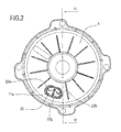
Figure 2 is a schematic top plan view of the motor in accordance with the present invention, in an assembly step; -
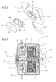
Figure 3 is a schematic perspective view of a succession of steps of assembling a part of the electric motor in accordance with the present invention; -
Figure 4 is a schematic view of the cross-section IV - IV fromFigure 2 ; -
Figure 5 is an enlarged view of the detail A fromFigure 4 ; -
Figure 6 is a schematic side view of an assembly step in accordance with the present invention; -
Figure 7 is a schematic side view of another assembly step in accordance with the present invention; -
Figure 8 is a schematic cross-section of a second embodiment of a motor in accordance with the present invention; -
Figure 9 is a schematic cross-section of a detail of a third embodiment of a motor in accordance with the present invention; -
Figure 10 is a schematic cross-section and a front view of a detail of a fourth embodiment of a motor in accordance with the present invention; -
Figure 11 is a scaled down view compared with the detail fromFigure 10 , of a detail of the fourth embodiment of the motor in accordance with the present invention; -
Figure 12 is a schematic cross-section of a portion of the fourth embodiment of the motor in accordance with the present invention; -
Figure 13 is a schematic front view of a lid of a fifth embodiment of a motor in accordance with the present invention; -
Figure 14 is a schematic side view of the lid ofFigure 13 ; -
Figure 15 is a schematic rear view of the lid ofFigure 13 . - With reference to the accompanying drawings and in particular with reference to
Figures 4 and8 , thenumeral 1 denotes an electric motor assembled in accordance with the present invention. - The description below refers specifically to an electric motor, but it shall be understood that the invention may also relate to other types of rotary electric machines, for example power generators, alternators and the like.
- The
electric motor 1 comprises, schematically, anouter casing 2 delimiting acontainment compartment 2a. - The
casing 2 consists of a substantially cup-shaped part orcontainer 3 and alid 4 connected to one another with connecting devices of the known type and therefore not illustrated in detail. - An electromagnetic unit consisting of a
stator unit 5 and arotary unit 6, of the substantially known type, is housed in thecasing 2. - The
rotary unit 6, able to rotate about an axis R, comprises ashaft 7 partly projecting outside thecasing 2. - As illustrated in
Figure 8 , themotor 1 shown is of the so-called "twin-shaft" type, that is to say, theshaft 7 and thecasing 2 are made in such a way that theshaft 7 axially comes out of the cup-shaped part 3 and thelid 4. - The
motor 1 comprises means 8 for supporting therotary unit 6 positioned inside thecasing 2. - In particular, the
rotary unit 6 is rotatably constrained to the cup-shaped part 3 and to thelid 4 bybearings - The
bearings lid 4 and to thecontainer 3 and theshaft 7 is inserted in them. - The
bearing 9 is of the sealed type to prevent infiltrations from outside through thebearing 9. - In the case of a twin-
shaft motor 1 thebearing 10 is also preferably sealed. - It should be noticed that the
bearing 9 is inserted in arelative cavity 9a made in thebase wall 3a of the cup-shaped part 3, whilst thelid 4 has acavity 10a for thebearing 10. - The
bearing 9 is locked in thecavity 9a preferably by means of caulking, as described in further detail below. - Moreover, in the preferred embodiment illustrated the
motor 1 comprises an O-ring 20 positioned between thebearing 9 and thebase wall 3a. - The
motor 1 also preferably comprises agasket 21, substantially tubular, positioned between thebearing 10 and thelid 4. - The
gasket 21 has aninner lip 21a positioned between thebearing 10 and thelid 4. - In practice, the
gasket 21 is inserted in thecavity 10a and thebearing 10 is in turn inserted in thegasket 21, pressing theinner lip 21a against thelid 4. -
Figure 4 in particular shows how themotor 1 comprises means 11 for supplying power to themotor 1, said means housed in thecasing 2. - In the embodiment illustrated, the power supply means 11 consist of a
brush holder 12 of the substantially known type. - It should be noticed that in the exploded diagram in
Figure 1 thebrush holder 12 is omitted in order to keep the diagram simple. - In particular with reference to
Figures 10, 11 and12 , themotor 1 comprises a substantially disk-shaped isolating element 28 positioned in such a way as to protect thelid 4 to prevent accidental short-circuits between the power supply means 11 and thecasing 2. - In particular, the
isolating element 28 is required if the power supply means 11 comprise brushes, not illustrated in detail, supplied by means of a respective metal braid, also not illustrated, which may accidentally make contact with thelid 4. - The isolating
element 28 has acentral hole 28a surrounding thecavity 10a of thebearing 10 and an opening 28b for supplying power to the power supply means 11 as described in more detail below. - It should be noticed that the
gasket 21 preferably has anouter lip 21b for holding theisolating element 28 in the correct position relative to thelid 4, in particular when thelid 4 is assembled on the cup-shaped part 3. - Advantageously, the
gasket 21 has a pair of annular thickenedportions 21c for obtaining a seal between thebearing 10 and therelative cavity 10a. - To guarantee the
motor 1 an effective seal against external agents, the motor has agasket 13 positioned between thelid 4 and the cup-shaped part 3. - With reference to
Figures 1 ,4 and8 , thegasket 13 is preferably of the type illustrated in the above-mentioned documentW02005/034309 which is incorporated herein by reference as a non-limiting example and for completeness of description. - Alternatively, the
gasket 13 is directly moulded on thelid 4 to simplifymotor 1 assembly, that is to say, thelid 4 is made during a first moulding step, and thegasket 13 is provided on thelid 4 during a second moulding step. - As illustrated in
Figure 9 , in a different embodiment, asealing material 30 is positioned between thelid 4 and the cup-shaped part 3 to form a seal between them. - In the embodiment illustrated, the
sealing material 30 is positioned on thelid 4 whilst, in alternative embodiments not illustrated, thematerial 30 is positioned on the edge of thecontainer 3. - The
lid 4 preferably has anannular groove 30a suitably shaped to receive the sealingmaterial 30. - In a preferred embodiment, the
sealing material 30 comprises an adhesive. - Advantageously, in another embodiment, the
sealing material 30 comprises a polyurethane material. - In that case, a polyurethane foam is dosed in the
annular groove 30a. The foam polymerises, substantially resulting in the formation of a gasket having a waterproof outer surface which encloses a foamy core with damping function particularly advantageous for taking uplid 4 closing play and tolerances. -
Figure 5 in particular shows how theshaft 7 has a substantiallyannular cavity 14, for anannular gasket 15 between theshaft 7 and thebearing 9. - As illustrated in
Figure 8 , theshaft 7 has a secondannular cavity 16 for a relative substantiallyannular gasket 17. - As illustrated in
Figure 3 , thelid 4 has anopening 18 for connection of the power supply means 11 to anexternal cable 19. - The
motor 1 preferably comprises an interconnectingelement 22 inserted in theopening 18 where the power supply means 11 are associated with thecable 19. - In particular the power supply means 11 comprise a pair of
pins opening 18 when thelid 4 is positioned on the cup-shapedpart 3. - The interconnecting
element 22 has a pair ofopenings pins lid 4. - The
cable 19 is associated with thepins - A closing
element 23 is inserted in theopening 18 to seal theopening 18, as described in more detail below. - The
element 23 has ahole 24 for injecting a sealing material into theopening 18. - It should be noticed that the
opening 18 and theclosing element 23 are shaped in such a way as to allow thecable 19 to pass to the outside of thecasing 2. - The method for assembling the
motor 1 comprises the steps of inserting thestator unit 5 in the cup-shapedpart 3 and locking it to the latter in a relatively known way. - The
rotary unit 6 supporting means 8, in particular thebearing 9, are locked in thebase wall 3a of the cup-shapedpart 3. - The
bearing 9 is inserted in thecavity 9a together with the O-ring 20 and locked in positioned by caulking thecavity 9a. - The
rotary unit 6 is then inserted in the cup-shapedpart 3 substantially at thestator unit 5. - In particular, the
shaft 7 is inserted through thebearing 9 and constrained to it. - It should be noticed that the
gasket 15, preferably of the "O-ring" type, being pressed in thecavity 14 between theshaft 7 and thebearing 9, guarantees amotor 1 seal against external agents where theshaft 7 comes out of thecasing 2. - As illustrated in
Figure 8 , in a substantially similar way, in the case of a twin-shaft motor 1, thegasket 17 pressed in thecavity 16 between theshaft 7 and thebearing 10 guarantees a seal against external agents at saidbearing 10. - The
brush holder 12 is inserted in the cup-shapedpart 3 and thelid 4 is positioned in such a way that it closes thepart 3. - It should be noticed that during this step the
lid 4 is not locked to the cup-shapedpart 3, but is placed in the position it has on thefinished motor 1 and held there. - It should be noticed that if the isolating
element 28 is required, it is held in the correct position by thegasket 21outer lip 21b. - Preferably, with the
motor 1 in this configuration, several electric tests are carried out in the substantially known way. - In particular, the motor rpm, noise and amperage draw are tested.
- As illustrated in
Figure 6 , with thelid 4 positioned on the cup-shapedpart 3 and thecasing 2 substantially closed, themotor 1 hermetic seal is tested. - The motor hermetic seal is preferably tested at the end of the electric tests.
- The
motor 1 hermetic seal is preferably tested by exposing thecasing 2 and therefore also thecompartment 2a to a different pressure relative to the outside environment. - In particular, the
motor 1 hermetic seal is tested by detecting any passage of a fluid between the outside environment and thecompartment 2a after application of said difference in pressure. - In the preferred embodiment illustrated the step of exposing the
compartment 2a to a different pressure is carried out by blowing a gas into thecasing 2 to bring the pressure in thecompartment 2a to values higher than the outside environment, that is to say, exposing thecompartment 2a to an overpressure relative to the outside environment. In particular, pneumatic means 25, of a substantially known type, are put in fluid communication with the inside of thecasing 2. - In more detail, a
hood 26 rests on thelid 4 in a hermetic way and the pneumatic means 25 engage theopening 18 in a sealed way. - The pneumatic means 25 blow a gas into the
casing 2 and if no gas leaks out of thecasing 2 then themotor 1 is definitely sealed. Preferably, during the action of the pneumatic means 25 the interconnectingelement 22 is inserted in theopening 18. Advantageously, themotor 1 hermetic seal can be tested by means of a sucking action from the inside of thecasing 2 towards the outside. The pneumatic means 25 put in fluid communication with thecompartment 2a substantially suck air out of thecompartment 2a until a vacuum is created in it, that is to say, thecompartment 2a is subjected to a lower pressure than the outside environment. - If, as the sucking action is continued, air passes from the outside environment into the
casing 2, this shows that the motor is not hermetically sealed. - It should be noticed that the step of testing the
motor 1 hermetic seal and the electric tests may be carried out in the same test station. - If the tests are carried out manually by an operator, they are preferably carried out in the same station, for example the
station 27 illustrated inFigure 6 . - Advantageously, when the
motor 1 is assembled in a production line, not illustrated, the electric and hermetic seal tests are carried out in two separate stations. - When the tests are complete, the
casing 2 is closed, that is to say, thelid 4 and the cup-shapedpart 3 are locked relative to one another in the substantially known way. - The
cable 19 is soldered to the power supply means 11 at the connectingelement 22. - Once the
lid 4 has been locked on the cup-shapedpart 3 and thecable 19 has been connected to the power supply means 11, theopening 18 is sealed. - The closing
element 23 is inserted in theopening 18 and driven into it. - As schematically illustrated in
Figure 7 , he sealing material, preferably adhesive, is then injected, in a substantially known way, into theopening 18 through thehole 24 in theclosing element 23. - It should be noticed that the connecting
element 22 functions as an element for collecting the sealing material and theopening 18 is completely sealed. - Another
motor 1 hermetic seal test is preferably advantageously feasible once the motor has been assembled, in particular if using thelid 4, moulded and comprising thebrush holder 12. - Hereinafter, for the sake of simplicity, said
lid 4, moulded and comprising thebrush holder 12, will be referred to simply as the brush holder lid 4a. - In this case, the lid 4a, with the sealing
material 30 on it, preferably adhesive, is used to close thecontainer 3. - The
motor 1 is immersed in a test liquid to check if any of the liquid enters thecompartment 2a. - The
motor 1 seal is preferably tested after thermal transients. - The
motor 1 is heated then immersed in the test liquid. - Preferably, once it has cooled, the
motor 1 is heated again then immersed in the fluid, which must not penetrate themotor 1 after the thermal expansions due to the sudden changes in temperature. - This procedure may be repeated several times as necessary.
- It should be noticed that the hermetic seal test involving immersion in the test fluid is feasible with any type of
motor 1. - In particular with reference to
Figures 13 ,14 and 15 , it should be noticed that the hermetic seal test involving immersion in the test fluid may advantageously be carried out onmotors 1 comprising the mouldedlid 4 also functioning as thebrush holder 12 support. Hereinafter, for the sake of simplicity, saidlid 4, moulded and comprising thebrush holder 12, will be referred to simply as the brush holder lid 4a. - Such motors do not have openings giving access to the
compartment 2a, since the brush holder lid 4a substantially houses apin 29 for connecting the lid 4a to theexternal cable 19 in a substantially known way. - It should be noticed that in such motors the seal between the brush holder lid 4a and the
container 3 is preferably obtained using the sealingmaterial 30. - The sealing
material 30 used with the brush holder lid 4a preferably comprises an adhesive. - In another embodiment, the sealing
material 30 comprises a silicone material or a polyurethane material. - The sealing
material 30 is preferably placed directly on the lid 4a when lid moulding is completed. - Advantageously, in an alternative embodiment, not illustrated, the brush holder lid 4a is closed on the cup-shaped
part 3 by inserting a relative gasket, as well as the sealing material, between them. Advantageously, said gasket is moulded on the brush holder lid 4a, that is to say, the brush holder lid 4a is obtained in a first moulding step and the gasket is provided on it in a second moulding step. - The invention brings important advantages.
- Thanks in particular to the hermetic seal test carried out with pneumatic means, the motor seal, created as a result of the gaskets present on the shaft, the gasket between the lid and the cup-shaped part and the special bearings used, is effectively tested.
- Said step is easy to carry out and so relatively inexpensive.
- Further seal guarantees are supported by the tests which may be carried out on the motor after thermal transients.
- The invention described above may be modified and adapted in several ways without thereby departing from the scope of the inventive concept, as defined in the claims herein.
- Moreover, all the details of the invention may be substituted by technically equivalent elements.
Claims (7)
- An electric motor comprising: an outer casing (2) formed by a substantially cup-shaped part or container (3) and by at least one lid (4, 4a); a stator unit (5) and a rotary unit (6) housed in the casing, the rotary unit (6) comprising a shaft (7) partly coming out of the casing (2); at least a bearing (9, 10) operating between the rotary unit (6) and the casing (2) to rotatably constrain the shaft (7) to the casing (2), the casing (2) having a cavity (9a) for the bearing (9, 10); power supply means (11) for the stator unit (5) or the rotary unit (6) inserted in the casing (2); sealing means (13, 30) positioned between the lid (4, 4a) and the substantially cup-shaped part (3), the motor being characterised in that the shaft (7) has at least one cavity (14, 16) for housing an annular gasket between the shaft (7) and the bearing (9, 10), the electric motor comprising an annular gasket (15, 17) positioned in the cavity (14, 16) between the shaft (7) and the bearing (9, 10).
- The motor according to claim 1, characterised in that it comprises a first and a second bearing (9, 10) constraining the rotary unit (6) to the cup shaped part (3) and to the lid (4) and a tubular gasket (21) having an inner lip (21a) positioned positioned between the second bearing (10) and the lid (4).
- The motor according to claim 2 characterized in that the cup-shaped part (3) presents a base wall (3a) provided with a first cavity (9a) and the lid (4) has a second cavity (10a), the first bearing (9) and the second bearing (10) being respectively inserted in the first cavity (9a) and in the second cavity (10a), the tubular gasket (21) being inserted in the second cavity (10a), the second bearing (10) pressing the inner lip (21a) 21a against the lid (4).
- The motor according to claim 3 characterized in that the tubular gasket (21) has a pair of annular thickened portions (21c) positioned between the second bearing (10) and the second cavity (10a).
- The motor according to claim 3 or 4, characterized in that it comprises a disk-shaped isolating element (28) positioned between the lid (4) and the power supply means (11) and having a central hole (28a) surrounding the second cavity (10a) and an opening (28b), the tubular gasket (21) having an outer lip (21b) holding the isolating element (28).
- The motor according to any of foregoing claim, characterised in that the the power supply means (11) comprise a bruh holder (12) and the sealing means (13, 30) comprise an elastomeric or silicone material material (30), the lid (4) being moulded in a single body with the brush holder (12) defining a bruh holder lid (4a).
- The motor according to claim 6, characterized in that it comprises a gasket moulded on the brush holder lid (4a) and inserted between the brush holder lid (4a) and the cup shaped part (3).
Applications Claiming Priority (2)
| Application Number | Priority Date | Filing Date | Title |
|---|---|---|---|
| IT000339A ITBO20060339A1 (en) | 2006-05-08 | 2006-05-08 | METHOD TO ASSEMBLE AN ELECTRIC MOTOR AND ENGINE OBTAINED WITH THIS METHOD |
| EP07734499.2A EP2022159B1 (en) | 2006-05-08 | 2007-05-08 | Method for assembling an electric motor and motor obtained using this method |
Related Parent Applications (2)
| Application Number | Title | Priority Date | Filing Date |
|---|---|---|---|
| EP07734499.2A Division-Into EP2022159B1 (en) | 2006-05-08 | 2007-05-08 | Method for assembling an electric motor and motor obtained using this method |
| EP07734499.2A Division EP2022159B1 (en) | 2006-05-08 | 2007-05-08 | Method for assembling an electric motor and motor obtained using this method |
Publications (2)
| Publication Number | Publication Date |
|---|---|
| EP2495848A2 true EP2495848A2 (en) | 2012-09-05 |
| EP2495848A3 EP2495848A3 (en) | 2017-03-22 |
Family
ID=38441963
Family Applications (2)
| Application Number | Title | Priority Date | Filing Date |
|---|---|---|---|
| EP07734499.2A Not-in-force EP2022159B1 (en) | 2006-05-08 | 2007-05-08 | Method for assembling an electric motor and motor obtained using this method |
| EP12169842.7A Withdrawn EP2495848A3 (en) | 2006-05-08 | 2007-05-08 | Electric motor |
Family Applications Before (1)
| Application Number | Title | Priority Date | Filing Date |
|---|---|---|---|
| EP07734499.2A Not-in-force EP2022159B1 (en) | 2006-05-08 | 2007-05-08 | Method for assembling an electric motor and motor obtained using this method |
Country Status (8)
| Country | Link |
|---|---|
| US (2) | US7768167B2 (en) |
| EP (2) | EP2022159B1 (en) |
| CN (2) | CN103001384B (en) |
| BR (1) | BRPI0711147A8 (en) |
| ES (1) | ES2668073T3 (en) |
| IT (1) | ITBO20060339A1 (en) |
| TR (1) | TR201806304T4 (en) |
| WO (1) | WO2007129205A2 (en) |
Cited By (1)
| Publication number | Priority date | Publication date | Assignee | Title |
|---|---|---|---|---|
| EP3883354A1 (en) * | 2020-03-17 | 2021-09-22 | ebm-papst Mulfingen GmbH & Co. KG | Electronic housing with leak test opening and sealing plug |
Families Citing this family (19)
| Publication number | Priority date | Publication date | Assignee | Title |
|---|---|---|---|---|
| ITBO20060339A1 (en) * | 2006-05-08 | 2007-11-09 | Spal Automotive Srl | METHOD TO ASSEMBLE AN ELECTRIC MOTOR AND ENGINE OBTAINED WITH THIS METHOD |
| DE102009000010A1 (en) * | 2009-01-02 | 2010-07-08 | Robert Bosch Gmbh | Electrically commutated electrical machine |
| DE202010006401U1 (en) | 2010-05-04 | 2011-10-12 | Brose Fahrzeugteile GmbH & Co. Kommanditgesellschaft, Würzburg | Electrical module connection of a motor vehicle |
| CN103169507A (en) * | 2011-12-22 | 2013-06-26 | 深圳市威尔德医疗电子有限公司 | Cavity body inside three-dimensional ultrasound probe used in ultrasound medical equipment |
| KR102177695B1 (en) * | 2012-10-01 | 2020-11-11 | 그라코 미네소타 인크. | Alternator for electrostatic spray gun |
| CN103795175A (en) * | 2012-10-31 | 2014-05-14 | 东明机电(深圳)有限公司 | Series-excited motor and manufacture method thereof |
| US9373986B2 (en) * | 2012-11-02 | 2016-06-21 | Rockwell Automation Technologies, Inc. | Method for providing servo motor rear bearing support, space for internal electronic packaging and IP sealing between motor and externally attached devices |
| ITBO20120682A1 (en) * | 2012-12-18 | 2014-06-19 | Spal Automotive Srl | ELECTRIC MACHINE |
| CN103078455B (en) * | 2012-12-27 | 2015-05-27 | 鞍山钢铁集团公司 | Mounting device and use method for motor end cover |
| KR102596664B1 (en) * | 2016-07-18 | 2023-11-02 | 엘지이노텍 주식회사 | Motor |
| US10707720B2 (en) * | 2018-01-05 | 2020-07-07 | Nidec Motor Corporation | Motor having improved stator core |
| US11649636B2 (en) * | 2018-10-09 | 2023-05-16 | Taylor Made Group, Llc | Tubular motor seal for extendable awning |
| EP3799268A1 (en) * | 2019-09-26 | 2021-03-31 | Mahle International GmbH | Assembly for a rotating electric machine |
| DE102020203279A1 (en) * | 2020-03-13 | 2021-09-16 | Robert Bosch Gesellschaft mit beschränkter Haftung | Drive device for an actuator |
| IT202100005513A1 (en) * | 2021-03-09 | 2022-09-09 | Te Connectivity Italia Distribution Srl | SYSTEM AND METHOD FOR CARRYING OUT LEAK TESTS |
| DE102021111907A1 (en) * | 2021-05-07 | 2022-11-10 | Bayerische Motoren Werke Aktiengesellschaft | Pressure compensation arrangement and electrical machine |
| DE102021115531A1 (en) | 2021-06-16 | 2022-12-22 | Dr. Ing. H.C. F. Porsche Aktiengesellschaft | Procedure for determining the tightness of an electric drive machine |
| CN115313729A (en) * | 2022-07-27 | 2022-11-08 | 哈尔滨工程大学 | Motor waterproof device of underwater vehicle control mechanism |
| US20240175777A1 (en) * | 2022-11-25 | 2024-05-30 | Ferrari S.P.A. | Electric machine for motor vehicles, method for testing the sealing of gaskets provided in such an electric machine, and motor vehicle axle provided with such electric machine |
Citations (2)
| Publication number | Priority date | Publication date | Assignee | Title |
|---|---|---|---|---|
| US5767596A (en) | 1996-10-03 | 1998-06-16 | General Electric Company | Dynamoelectric machine and processes for making the same |
| WO2005034309A1 (en) | 2003-09-30 | 2005-04-14 | Spal Automotive S.R.L. | Electric motor for electric fan and assembly method therefor |
Family Cites Families (27)
| Publication number | Priority date | Publication date | Assignee | Title |
|---|---|---|---|---|
| US2725012A (en) * | 1952-03-22 | 1955-11-29 | Mcgraw Electric Co | Motor-pump unit |
| US2910003A (en) * | 1955-03-11 | 1959-10-27 | American Crucible Products Com | Pump control |
| US3579037A (en) * | 1968-11-12 | 1971-05-18 | Oceanautic Mfg And Research Co | Portable tool |
| US3814961A (en) * | 1972-08-02 | 1974-06-04 | Ambac Ind | Trolling motor structure |
| NL8102875A (en) * | 1980-06-26 | 1982-01-18 | Toyo Denki Kogyosho Co Ltd | METHOD AND MECHANISM FOR CONTROLLING PRESSURE ON AXLE SEALING PART OF AN APPARATUS. |
| JPS5754832A (en) | 1980-09-19 | 1982-04-01 | Hitachi Ltd | Airtight inspection |
| DE3344419C2 (en) * | 1983-12-08 | 1986-12-11 | Klein, Schanzlin & Becker Ag, 6710 Frankenthal | Procedure for testing electric motors for leaks |
| US4847528A (en) * | 1987-02-10 | 1989-07-11 | Mitsuba Electric Manufacturing Co., Ltd. | Plastic molding on penetration metal, particularly on motor end plate |
| DE59006072D1 (en) * | 1990-08-23 | 1994-07-14 | Siemens Ag | Motor-gear drive unit, in particular motor vehicle window regulator drive. |
| US5087846A (en) * | 1990-12-17 | 1992-02-11 | Wright John J | Submersible motor housing |
| US5259629A (en) | 1991-02-19 | 1993-11-09 | Ishikawa Gasket Co., Ltd. | Steel laminate gasket with dowel engaging device |
| EP0640507B1 (en) * | 1992-05-12 | 2003-04-16 | Seiko Epson Corporation | Electric vehicle |
| DE4235437C1 (en) | 1992-10-21 | 1993-09-02 | Gloeckler-Dichtungen Guenter Hemmrich Gmbh, 75015 Bretten, De | Engine cylinder-head-cover joint - is joined to edge of oil-splash-cowl extending for full cover length |
| US5895207A (en) | 1993-06-17 | 1999-04-20 | Itt Automotive Europe, Gmbh | Electric motor-pump assembly |
| US6011339A (en) * | 1996-01-18 | 2000-01-04 | Shibaura Engineering Works Co., Ltd. | Motor mounted in a vehicle |
| CZ410497A3 (en) * | 1996-12-20 | 1998-07-15 | W. Schlafhorst Ag Und Co. | Axial mounting of open-end spinning machine |
| CN1574558A (en) * | 1997-07-19 | 2005-02-02 | 东京研发股份有限公司 | Motor |
| JPH11126647A (en) | 1997-10-21 | 1999-05-11 | Yazaki Corp | Annular packing and mounting structure of annular packing |
| EP1045174A3 (en) | 1999-04-13 | 2002-10-16 | Bridgestone Corporation | Gasket fitted to frame and process for producing the same |
| JP2000337391A (en) * | 1999-05-28 | 2000-12-05 | Minebea Co Ltd | Bearing device |
| CN2398765Y (en) | 1999-08-13 | 2000-09-27 | 金星(礼品)有限公司 | Sealed Motor Unit |
| US6204577B1 (en) * | 2000-01-05 | 2001-03-20 | Jeffrey Eliot Chottiner | Method and apparatus for space-saving installation of a starter-alternator |
| AT411289B (en) | 2000-09-06 | 2003-11-25 | Dft Maschb Gmbh | SEAL DEVICE |
| US6588762B2 (en) | 2001-11-29 | 2003-07-08 | Sauer-Danfoss Inc. | Lathe cut face seal and method for sealing irregularly shaped cavity |
| GB0202841D0 (en) * | 2002-02-07 | 2002-03-27 | Johnson Electric Sa | Blower motor |
| DE20302174U1 (en) * | 2003-02-11 | 2004-09-09 | Minebea Co., Ltd. | Shaft seal for an electric motor and electric motor, in particular for an automatic transmission of a motor vehicle |
| ITBO20060339A1 (en) * | 2006-05-08 | 2007-11-09 | Spal Automotive Srl | METHOD TO ASSEMBLE AN ELECTRIC MOTOR AND ENGINE OBTAINED WITH THIS METHOD |
-
2006
- 2006-05-08 IT IT000339A patent/ITBO20060339A1/en unknown
-
2007
- 2007-05-08 WO PCT/IB2007/001184 patent/WO2007129205A2/en not_active Ceased
- 2007-05-08 BR BRPI0711147A patent/BRPI0711147A8/en not_active Application Discontinuation
- 2007-05-08 EP EP07734499.2A patent/EP2022159B1/en not_active Not-in-force
- 2007-05-08 CN CN201210484291.7A patent/CN103001384B/en not_active Expired - Fee Related
- 2007-05-08 EP EP12169842.7A patent/EP2495848A3/en not_active Withdrawn
- 2007-05-08 ES ES07734499.2T patent/ES2668073T3/en active Active
- 2007-05-08 TR TR2018/06304T patent/TR201806304T4/en unknown
- 2007-05-08 US US12/226,684 patent/US7768167B2/en not_active Expired - Fee Related
- 2007-05-08 CN CN200780016770.3A patent/CN101443984B/en not_active Expired - Fee Related
-
2010
- 2010-06-18 US US12/818,400 patent/US8076810B2/en not_active Expired - Fee Related
Patent Citations (2)
| Publication number | Priority date | Publication date | Assignee | Title |
|---|---|---|---|---|
| US5767596A (en) | 1996-10-03 | 1998-06-16 | General Electric Company | Dynamoelectric machine and processes for making the same |
| WO2005034309A1 (en) | 2003-09-30 | 2005-04-14 | Spal Automotive S.R.L. | Electric motor for electric fan and assembly method therefor |
Cited By (1)
| Publication number | Priority date | Publication date | Assignee | Title |
|---|---|---|---|---|
| EP3883354A1 (en) * | 2020-03-17 | 2021-09-22 | ebm-papst Mulfingen GmbH & Co. KG | Electronic housing with leak test opening and sealing plug |
Also Published As
| Publication number | Publication date |
|---|---|
| ITBO20060339A1 (en) | 2007-11-09 |
| EP2022159B1 (en) | 2018-04-11 |
| US8076810B2 (en) | 2011-12-13 |
| CN103001384A (en) | 2013-03-27 |
| ES2668073T3 (en) | 2018-05-16 |
| TR201806304T4 (en) | 2018-06-21 |
| CN101443984B (en) | 2013-01-02 |
| US20100251538A1 (en) | 2010-10-07 |
| CN101443984A (en) | 2009-05-27 |
| US7768167B2 (en) | 2010-08-03 |
| BRPI0711147A8 (en) | 2018-04-24 |
| EP2495848A3 (en) | 2017-03-22 |
| EP2022159A2 (en) | 2009-02-11 |
| US20090121569A1 (en) | 2009-05-14 |
| WO2007129205A2 (en) | 2007-11-15 |
| CN103001384B (en) | 2015-12-23 |
| BRPI0711147A2 (en) | 2011-08-23 |
| WO2007129205A3 (en) | 2008-01-31 |
Similar Documents
| Publication | Publication Date | Title |
|---|---|---|
| EP2022159B1 (en) | Method for assembling an electric motor and motor obtained using this method | |
| KR101895067B1 (en) | Electric motor, in particular radiator fan motor | |
| JP6280771B2 (en) | Blower, motor and manufacturing method thereof | |
| US6205644B1 (en) | Method of assembling an electric motor | |
| CN206506389U (en) | Stator unit, motor and fan in parallel | |
| JP2013188091A (en) | Air blower | |
| JP2018178898A (en) | Blowing device, blowing unit, and method of manufacturing blowing device | |
| US7586227B2 (en) | Electric motor for electric fan and assembly method therefor | |
| US10873234B2 (en) | Closure system for electric motor and corresponding closing procedure | |
| JP5112821B2 (en) | Motor structure | |
| CN217010524U (en) | Dry-wet dual-purpose brushless dust collector motor | |
| CN206992848U (en) | Fan motor | |
| JP2003172300A (en) | Axial flow fan | |
| CN208241468U (en) | A kind of car combustion engine alternating current generator carbon brush chamber | |
| CN218569965U (en) | Stator winding protection structure of refrigerant motor | |
| KR200460845Y1 (en) | Motor | |
| CN108566020A (en) | A kind of car combustion engine alternating current generator carbon brush chamber | |
| CN115428264A (en) | Hermetic terminal, electric compressor using the same, and connection method | |
| CN218301028U (en) | Sealed brushless external rotor motor | |
| CN210053305U (en) | Brushless speed reducing motor | |
| US20090000838A1 (en) | Electric Motor for a Motor Vehicle and Associated Assembly Method | |
| CN101372974B (en) | Sealed compressor | |
| JP3101419U (en) | Rotating machine | |
| KR100376134B1 (en) | Bearing Fixing Apparatus of Resin Motor | |
| EP3836369A1 (en) | Rotating electric machine and ventilation mode conversion plug for a rotating electric machine |
Legal Events
| Date | Code | Title | Description |
|---|---|---|---|
| PUAI | Public reference made under article 153(3) epc to a published international application that has entered the european phase |
Free format text: ORIGINAL CODE: 0009012 |
|
| AC | Divisional application: reference to earlier application |
Ref document number: 2022159 Country of ref document: EP Kind code of ref document: P |
|
| AK | Designated contracting states |
Kind code of ref document: A2 Designated state(s): AT BE BG CH CY CZ DE DK EE ES FI FR GB GR HU IE IS IT LI LT LU LV MC MT NL PL PT RO SE SI SK TR |
|
| PUAL | Search report despatched |
Free format text: ORIGINAL CODE: 0009013 |
|
| AK | Designated contracting states |
Kind code of ref document: A3 Designated state(s): AT BE BG CH CY CZ DE DK EE ES FI FR GB GR HU IE IS IT LI LT LU LV MC MT NL PL PT RO SE SI SK TR |
|
| RIC1 | Information provided on ipc code assigned before grant |
Ipc: H02K 5/10 20060101ALN20170210BHEP Ipc: H02K 5/22 20060101ALN20170210BHEP Ipc: H02K 15/14 20060101AFI20170210BHEP |
|
| 17P | Request for examination filed |
Effective date: 20170922 |
|
| RBV | Designated contracting states (corrected) |
Designated state(s): AT BE BG CH CY CZ DE DK EE ES FI FR GB GR HU IE IS IT LI LT LU LV MC MT NL PL PT RO SE SI SK TR |
|
| STAA | Information on the status of an ep patent application or granted ep patent |
Free format text: STATUS: THE APPLICATION IS DEEMED TO BE WITHDRAWN |
|
| 18D | Application deemed to be withdrawn |
Effective date: 20181201 |