EP3883342B1 - Induction heating assembly for a vapour generating device - Google Patents
Induction heating assembly for a vapour generating device Download PDFInfo
- Publication number
- EP3883342B1 EP3883342B1 EP21173626.9A EP21173626A EP3883342B1 EP 3883342 B1 EP3883342 B1 EP 3883342B1 EP 21173626 A EP21173626 A EP 21173626A EP 3883342 B1 EP3883342 B1 EP 3883342B1
- Authority
- EP
- European Patent Office
- Prior art keywords
- induction
- generating device
- heating assembly
- induction coil
- vapour generating
- Prior art date
- Legal status (The legal status is an assumption and is not a legal conclusion. Google has not performed a legal analysis and makes no representation as to the accuracy of the status listed.)
- Active
Links
Images


Classifications
-
- H—ELECTRICITY
- H05—ELECTRIC TECHNIQUES NOT OTHERWISE PROVIDED FOR
- H05B—ELECTRIC HEATING; ELECTRIC LIGHT SOURCES NOT OTHERWISE PROVIDED FOR; CIRCUIT ARRANGEMENTS FOR ELECTRIC LIGHT SOURCES, IN GENERAL
- H05B6/00—Heating by electric, magnetic or electromagnetic fields
- H05B6/02—Induction heating
- H05B6/10—Induction heating apparatus, other than furnaces, for specific applications
- H05B6/105—Induction heating apparatus, other than furnaces, for specific applications using a susceptor
- H05B6/108—Induction heating apparatus, other than furnaces, for specific applications using a susceptor for heating a fluid
-
- A—HUMAN NECESSITIES
- A24—TOBACCO; CIGARS; CIGARETTES; SIMULATED SMOKING DEVICES; SMOKERS' REQUISITES
- A24F—SMOKERS' REQUISITES; MATCH BOXES; SIMULATED SMOKING DEVICES
- A24F40/00—Electrically operated smoking devices; Component parts thereof; Manufacture thereof; Maintenance or testing thereof; Charging means specially adapted therefor
- A24F40/40—Constructional details, e.g. connection of cartridges and battery parts
- A24F40/42—Cartridges or containers for inhalable precursors
-
- A—HUMAN NECESSITIES
- A24—TOBACCO; CIGARS; CIGARETTES; SIMULATED SMOKING DEVICES; SMOKERS' REQUISITES
- A24F—SMOKERS' REQUISITES; MATCH BOXES; SIMULATED SMOKING DEVICES
- A24F40/00—Electrically operated smoking devices; Component parts thereof; Manufacture thereof; Maintenance or testing thereof; Charging means specially adapted therefor
- A24F40/40—Constructional details, e.g. connection of cartridges and battery parts
- A24F40/46—Shape or structure of electric heating means
- A24F40/465—Shape or structure of electric heating means specially adapted for induction heating
-
- A—HUMAN NECESSITIES
- A24—TOBACCO; CIGARS; CIGARETTES; SIMULATED SMOKING DEVICES; SMOKERS' REQUISITES
- A24F—SMOKERS' REQUISITES; MATCH BOXES; SIMULATED SMOKING DEVICES
- A24F40/00—Electrically operated smoking devices; Component parts thereof; Manufacture thereof; Maintenance or testing thereof; Charging means specially adapted therefor
- A24F40/50—Control or monitoring
- A24F40/57—Temperature control
-
- A—HUMAN NECESSITIES
- A24—TOBACCO; CIGARS; CIGARETTES; SIMULATED SMOKING DEVICES; SMOKERS' REQUISITES
- A24F—SMOKERS' REQUISITES; MATCH BOXES; SIMULATED SMOKING DEVICES
- A24F40/00—Electrically operated smoking devices; Component parts thereof; Manufacture thereof; Maintenance or testing thereof; Charging means specially adapted therefor
- A24F40/90—Arrangements or methods specially adapted for charging batteries thereof
-
- A—HUMAN NECESSITIES
- A24—TOBACCO; CIGARS; CIGARETTES; SIMULATED SMOKING DEVICES; SMOKERS' REQUISITES
- A24F—SMOKERS' REQUISITES; MATCH BOXES; SIMULATED SMOKING DEVICES
- A24F47/00—Smokers' requisites not otherwise provided for
-
- H—ELECTRICITY
- H01—ELECTRIC ELEMENTS
- H01F—MAGNETS; INDUCTANCES; TRANSFORMERS; SELECTION OF MATERIALS FOR THEIR MAGNETIC PROPERTIES
- H01F38/00—Adaptations of transformers or inductances for specific applications or functions
- H01F38/14—Inductive couplings
-
- H—ELECTRICITY
- H02—GENERATION; CONVERSION OR DISTRIBUTION OF ELECTRIC POWER
- H02J—CIRCUIT ARRANGEMENTS OR SYSTEMS FOR SUPPLYING OR DISTRIBUTING ELECTRIC POWER; SYSTEMS FOR STORING ELECTRIC ENERGY
- H02J50/00—Circuit arrangements or systems for wireless supply or distribution of electric power
- H02J50/10—Circuit arrangements or systems for wireless supply or distribution of electric power using inductive coupling
-
- H—ELECTRICITY
- H02—GENERATION; CONVERSION OR DISTRIBUTION OF ELECTRIC POWER
- H02J—CIRCUIT ARRANGEMENTS OR SYSTEMS FOR SUPPLYING OR DISTRIBUTING ELECTRIC POWER; SYSTEMS FOR STORING ELECTRIC ENERGY
- H02J7/00—Circuit arrangements for charging or depolarising batteries or for supplying loads from batteries
- H02J7/0042—Circuit arrangements for charging or depolarising batteries or for supplying loads from batteries characterised by the mechanical construction
- H02J7/0044—Circuit arrangements for charging or depolarising batteries or for supplying loads from batteries characterised by the mechanical construction specially adapted for holding portable devices containing batteries
-
- H—ELECTRICITY
- H02—GENERATION; CONVERSION OR DISTRIBUTION OF ELECTRIC POWER
- H02J—CIRCUIT ARRANGEMENTS OR SYSTEMS FOR SUPPLYING OR DISTRIBUTING ELECTRIC POWER; SYSTEMS FOR STORING ELECTRIC ENERGY
- H02J7/00—Circuit arrangements for charging or depolarising batteries or for supplying loads from batteries
- H02J7/02—Circuit arrangements for charging or depolarising batteries or for supplying loads from batteries for charging batteries from AC mains by converters
-
- H—ELECTRICITY
- H04—ELECTRIC COMMUNICATION TECHNIQUE
- H04B—TRANSMISSION
- H04B5/00—Near-field transmission systems, e.g. inductive or capacitive transmission systems
- H04B5/20—Near-field transmission systems, e.g. inductive or capacitive transmission systems characterised by the transmission technique; characterised by the transmission medium
- H04B5/24—Inductive coupling
- H04B5/26—Inductive coupling using coils
-
- H—ELECTRICITY
- H04—ELECTRIC COMMUNICATION TECHNIQUE
- H04B—TRANSMISSION
- H04B5/00—Near-field transmission systems, e.g. inductive or capacitive transmission systems
- H04B5/70—Near-field transmission systems, e.g. inductive or capacitive transmission systems specially adapted for specific purposes
- H04B5/79—Near-field transmission systems, e.g. inductive or capacitive transmission systems specially adapted for specific purposes for data transfer in combination with power transfer
-
- H—ELECTRICITY
- H05—ELECTRIC TECHNIQUES NOT OTHERWISE PROVIDED FOR
- H05B—ELECTRIC HEATING; ELECTRIC LIGHT SOURCES NOT OTHERWISE PROVIDED FOR; CIRCUIT ARRANGEMENTS FOR ELECTRIC LIGHT SOURCES, IN GENERAL
- H05B6/00—Heating by electric, magnetic or electromagnetic fields
- H05B6/02—Induction heating
- H05B6/04—Sources of current
-
- H—ELECTRICITY
- H05—ELECTRIC TECHNIQUES NOT OTHERWISE PROVIDED FOR
- H05B—ELECTRIC HEATING; ELECTRIC LIGHT SOURCES NOT OTHERWISE PROVIDED FOR; CIRCUIT ARRANGEMENTS FOR ELECTRIC LIGHT SOURCES, IN GENERAL
- H05B6/00—Heating by electric, magnetic or electromagnetic fields
- H05B6/02—Induction heating
- H05B6/06—Control, e.g. of temperature, of power
-
- H—ELECTRICITY
- H05—ELECTRIC TECHNIQUES NOT OTHERWISE PROVIDED FOR
- H05B—ELECTRIC HEATING; ELECTRIC LIGHT SOURCES NOT OTHERWISE PROVIDED FOR; CIRCUIT ARRANGEMENTS FOR ELECTRIC LIGHT SOURCES, IN GENERAL
- H05B6/00—Heating by electric, magnetic or electromagnetic fields
- H05B6/02—Induction heating
- H05B6/10—Induction heating apparatus, other than furnaces, for specific applications
- H05B6/105—Induction heating apparatus, other than furnaces, for specific applications using a susceptor
-
- H—ELECTRICITY
- H05—ELECTRIC TECHNIQUES NOT OTHERWISE PROVIDED FOR
- H05B—ELECTRIC HEATING; ELECTRIC LIGHT SOURCES NOT OTHERWISE PROVIDED FOR; CIRCUIT ARRANGEMENTS FOR ELECTRIC LIGHT SOURCES, IN GENERAL
- H05B6/00—Heating by electric, magnetic or electromagnetic fields
- H05B6/02—Induction heating
- H05B6/36—Coil arrangements
-
- A—HUMAN NECESSITIES
- A24—TOBACCO; CIGARS; CIGARETTES; SIMULATED SMOKING DEVICES; SMOKERS' REQUISITES
- A24F—SMOKERS' REQUISITES; MATCH BOXES; SIMULATED SMOKING DEVICES
- A24F40/00—Electrically operated smoking devices; Component parts thereof; Manufacture thereof; Maintenance or testing thereof; Charging means specially adapted therefor
- A24F40/20—Devices using solid inhalable precursors
Definitions
- the present invention relates to an induction heating assembly for a vapour generating device.
- Devices which heat, rather than burn, a substance to produce a vapour for inhalation have become popular with consumers in recent years.
- Such devices can use one of a number of different approaches to provide heat to the substance.
- One such approach is a vapour generating device which employs an inductive heating system.
- an induction coil hereinafter also referred to as an inductor
- a susceptor is provided with the vapour generation substance.
- Electrical energy is provided to the inductor when a user activates the device which in turn creates an electromagnetic field.
- the susceptor couples with the field and generates heat which is transferred to the substance and vapour is created as the substance is heated.
- WO 2015/177253 A1 discloses an inductive heating device for aerosol generation.
- the respective teaching addresses the problem of energy efficiency and proposes an induction coil of flattened wire material.
- An internal electric power source can be a rechargeable battery that can be connected to an external power source as a charging device.
- WO 2017/109448 A2 discloses the provision of several induction coils.
- a comms/user interface can be employed to instruct the e-cigarette to selectively activate different coils.
- a button is provided that is attributed to the activation of the device.
- US 2015/0320116 A1 discloses a vaporizer device that heats up inductively a wick element that is in contact with a vaporizable substance.
- the device has a button that allows a user to interact with the device.
- an induction heating assembly for a vapour generating device, the heating assembly comprising a rechargeable power source; and an induction coil; wherein the induction coil is arranged to heat, in use, a susceptor and is also arranged to receive, in use, an electromagnetic field generated by an external source to charge the power source.
- the induction coil for both emitting and receiving an electromagnetic field, it is possible to reliably provide inductive heating and inductive charging from the same member in a vapour generating device. This leads to a reduced component count improving size, weight, production cost and safety of the device.
- the susceptor may comprise one or more of, but not limited to, aluminium, iron, nickel, stainless steel and alloys thereof (e.g. Nickel Chromium). With the application of an electromagnetic field in its vicinity, the susceptor may generate heat due to eddy currents and magnetic hysteresis losses resulting in a conversion of energy from electromagnetic to heat.
- the induction heating assembly further comprises an inverter arranged to change a direct current from the power source to an alternating high-frequency current; a rectifier arranged to change an alternating high-frequency current from the induction coil to a direct current; and an induction controller arranged to be, in use, in electrical connection with the power source, the induction coil, the rectifier and with the inverter such that, in use, the alternating high-frequency current can be selectively supplied to the induction coil and a susceptor can be inductively heated by the induction coil and, in use, a direct current can be selectively supplied to the power source when power is received at the induction coil in the form of an electromagnetic field generated by an external source, to inductively charge the power source.
- an inverter arranged to change a direct current from the power source to an alternating high-frequency current
- a rectifier arranged to change an alternating high-frequency current from the induction coil to a direct current
- an induction controller arranged to be, in use, in electrical connection with the
- the induction controller provides a means for controlling the induction capabilities of the heating assembly, by selectively supplying electrical current to the induction coil and the power source. This allows the user of the device to efficiently control the extent of both the heating and the charging functionalities through the induction coil and to supply electrical current only when it is needed.
- the use of a single control unit to control the two functionalities through the induction coil reduces the component count and improves the safety of the heating assembly.
- the inclusion of an inverter and rectifier is advantageous in some situations in which the current within the heating assembly needs to be switched between alternating and direct current.
- the assembly may be arranged to operate in use with a fluctuating electromagnetic field having a magnetic flux density of between approximately 0.5 T and approximately 2.0 T at the point of highest concentration.
- the power source and circuitry may be configured to operate at a high frequency.
- the power source and circuitry may be configured to operate at a frequency of between approximately 80 kHz and approximately 500 kHz, preferably between approximately 150 kHz and approximately 250 kHz, more preferably 200 kHz.
- the induction coil may comprise any suitable material, typically the induction coil may comprise a Litz wire or a Litz cable.
- the heating assembly may take any shape and form, it may be arranged to take substantially the form of the induction coil, to reduce excess material use.
- the induction coil is substantially cylindrical in shape.
- the circular cross-section of a cylindrical induction coil is ideal for inserting a body to be inductively heated and heating the body uniformly, and leads to a shape of a heating assembly which is comfortable for the user to hold.
- the inverter and the rectifier are the same member arranged to selectively change a direct current from the power source to an alternating high-frequency current, and to selectively change an alternating high-frequency current from the induction coil to a direct current.
- the heating assembly may be charged by placing an external source of electromagnetic field in proximity to the induction coil.
- the external source may comprise an external induction coil for receiving and transmitting an electromagnetic field. Whilst the external source may interact with the induction coil in any fashion, typically the heating assembly is arranged to receive at least a portion of an external source of an electromagnetic field within its volume.
- the heating assembly By placing a portion of the external source inside the heating assembly (in some examples, by providing a projection (forming part of the external source) which can be inserted into the heating compartment when no body/capsule is located in the compartment), it is possible to ensure a safe and compact wireless connection between the external source of electromagnetic field and the induction coil of the heating assembly.
- This arrangement ensures that the electromagnetic coupling between the induction coil and external source is strong, to increase the efficiency of inductive charging to the power source of the induction heating assembly.
- the heating assembly acts as a shield against electromagnetic field while charging.
- the assembly is arranged to be, in use, inserted in the volume of an external source of an electromagnetic field.
- the external source may have an opening and a portion of its internal volume within which the assembly may be inserted.
- the external source may have a through hole therein such that its internal perimeter allows the assembly to be inserted therethrough. This allows the mouthpiece to be exposed while operating in connection with a compact external source, even in examples where the mouthpiece encloses the heating compartment when attached to the vapour generating device.
- the device may be provided with means for fixing the position of the external source in relation to the induction heating assembly.
- a vapour generating device comprising: an induction heating assembly according to the first aspect; a heating compartment arranged to receive a body comprising a vaporisable substance and an induction heatable susceptor; an air inlet arranged to provide air to the heating compartment; an air outlet in communication with the heating compartment.
- the body may be a capsule which includes in use a vaporisable substance inside an air permeable shell.
- the air permeable material may be a material which is electrically insulating and non-magnetic. The material may have a high air permeability to allow air to flow through the material with a resistance to high temperatures. Examples of suitable air permeable materials include cellulose fibres, paper, cotton and silk. The air permeable material may also act as a filter.
- the body may be a vaporisable substance wrapped in paper.
- the body may be a vaporisable substance held inside a material that is not air permeable, but which comprises appropriate perforation or openings to allow air flow.
- the body may be the vaporisable substance itself.
- the body may be formed substantially in the shape of a stick.
- the vaporisable substance may be any type of solid or semi-solid material.
- Example types of vaporisable solids include powder, granules, pellets, shreds, strands, porous material or sheets.
- the substance may comprise plant derived material and in particular, the substance may comprise tobacco.
- the vaporisable substance may comprise an aerosol-former.
- aerosol-formers include polyhyrdric alcohols and mixtures thereof such as glycerine or propylene glycol.
- the vaporisable substance may comprise an aerosol-former content of between approximately 5% and approximately 50% on a dry weight basis.
- the vaporisable substance may comprise an aerosol-former content of approximately 15% on a dry weight basis.
- the vaporisable substance may be the aerosol-former itself.
- the vaporisable substance may be liquid.
- the body may have a liquid retaining substance (e.g. a bundle of fibres, porous material such as ceramic, etc.) which retains the liquid to be vaporised by a vaporiser such as a heater, and allows a vapour to be formed and released or emitted from the liquid retaining substance towards the air outlet for inhalation by a user.
- a liquid retaining substance e.g. a bundle of fibres, porous material such as ceramic, etc.
- the vaporisable substance may release volatile compounds.
- the volatile compounds may include nicotine or flavour compounds such as tobacco flavouring.
- the induction coil produces an electromagnetic field when operating to heat a susceptor
- any member comprising an induction heatable susceptor will be heated when placed in proximity to the device in operation, and as such there is no restriction on the shape and form of the body being received by the heating compartment.
- the body to be heated is cylindrical in shape and as such the heating compartment is arranged to receive a substantially cylindrical vaporisable article.
- the ability of the heating compartment to receive a substantially cylindrical member to be heated is advantageous as, often, vaporisable substances and tobacco products in particular, are packaged and sold in a cylindrical form.
- a vapour generating device charging system comprising: the induction heating assembly according to the first aspect; a charging device comprising a charging coil arranged to induce a current in the induction coil of the induction heating assembly by producing an electromagnetic field.
- the charging device may take any shape and form, preferably the charging device is substantially cylindrical.
- a method of charging a vapour generating device comprising the steps of: placing a charging device in proximity to an induction heating assembly of the vapour generating device, the induction heating assembly comprising a rechargeable power source and an induction heating coil; and transferring power from the charging device in the form of an electromagnetic field to the induction heating coil of the heating assembly to supply charge to the rechargeable power source.
- the induction heating coil of the vapour generating device By using the induction heating coil of the vapour generating device to provide inductive charging to the power source of the device, it is possible to provide wireless charging to the device without the need for a separate second induction arrangement for charging.
- the charging device may be arranged to interact with the induction coil in any fashion, preferably, a portion of the charging device is at least partially inserted in a volume of the induction heating assembly. This ensures that a proper connection is maintained between the charging device and the induction heating coil to provide a safe and reliable coupling to charge the power source.
- At least a portion of the induction heating assembly may be at least partially inserted in a volume of the charging device.
- an electromagnetic field for charging from outside the induction heating assembly there may be situations in which it is advantageous to provide an electromagnetic field for charging from outside the induction heating assembly.
- the heating assembly arranged to be inserted in an external charging device, it is possible to free up the internal space of the assembly (e.g. internal space of the heating compartment) to be occupied by a substance to be heated (e.g. a body/capsule).
- the internal space may be defined radially inward of the induction coil and may be arranged to receive a body comprising a vaporisable substance and an induction heatable susceptor or susceptors, for example as described above.
- the external charging device may include a primary charging coil (which is operable to induce a current in the induction coil of the vapour generating device) which may be arranged to be substantially co-axial with the induction coil of the vapour generating device and substantially overlapping therewith, when they are coupled together in a charging configuration.
- a primary charging coil which is operable to induce a current in the induction coil of the vapour generating device
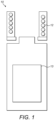
- FIG. 1 schematically illustrates an induction heating assembly 10 according to an embodiment of the present invention.
- the heating assembly 10 includes an induction coil 12 and a rechargeable power source 13.
- the power source 13 and the induction coil 12 are placed in electrical connection such that electrical power can be selectively transmitted between the two components.
- the induction coil 12 is arranged to heat an external susceptor by receiving electrical power from the power source 13 and producing an electromagnetic field.
- the induction coil 12 is further arranged to receive an externally generated electromagnetic field, to selectively induce an electrical current to charge the rechargeable power source 13.
- the induction coil 12 is substantially cylindrical such that the form of the induction heating assembly 10 is also substantially cylindrical.
- an alternating current changed from a direct current supplied by the power source 13 flows through the induction coil 12 to generate a controlled electromagnetic field in a region near the coil 12.
- the electromagnetic field generated provides a source for an external susceptor to absorb the electromagnetic energy and convert it to heat, thereby achieving induction heating.
- the induction heating assembly 10 of Figure 1 can also be operated to inductively charge the power source 13 when an external source of electromagnetic field is placed near the induction coil 12.
- the induction coil 12 interacts with an external field to absorb electromagnetic energy and induce an alternating current, which is changed to a direct current and transferred to the power source 13 to provide inductive charging.
- the induction coil 12 provides means for both the heating and the charging functionalities of the induction heating assembly 10.
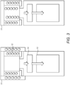
- the induction heating assembly 10 further comprises an induction controller 14, as shown Figures 2A and 2B .
- the induction controller 14 is arranged to be, in use, in electrical connection with the power source 13 and the induction coil 12, so as to selectively control the electrical current flowing between the power source 13 and the induction coil 12 such that the extent of heating or charging may be regulated.
- the induction controller 14 is capable of being manually operated by the user to select a heat setting, or programmed to automatically adjust the current through the induction coil 12 according to predetermined parameters.
- Figure 2A illustrates the flow of current through the induction heating assembly 10 when operating to heat an external susceptor.
- Electrical current from the power source 13, converted to a high-frequency alternating current by the inverter, is selectively supplied to the induction coil 12 by the induction controller 14.
- the alternating current in the induction coil 12 produces a dynamic electromagnetic field in the region of the coil 12, which can be absorbed by an external susceptor to achieve inductive heating.
- FIG 2B illustrates the flow of current through the induction heating assembly 10 when operating to charge the rechargeable power source 13.
- Power is received at the induction coil 12 in the form of a dynamic electromagnetic field generated by an external source.
- the electromagnetic field produces an electromotive force in the induction coil 12 to generate a high-frequency alternating electrical current.
- the alternating current from the induction coil 12, converted to a direct current by the rectifier, is selectively supplied to the rechargeable power source 13 by the induction controller 14.
- the rechargeable power source 13 can be inductively and wirelessly charged by an external source of electromagnetic field, using the induction coil 12 as a receiving susceptor (or equivalently as the secondary winding of a transformer arrangement as is well-known in the art of inductive charging).
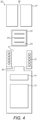
- the induction heating assembly 10 is capable of being operated to charge the power source 13 in either of the above configurations, with the configuration being chosen to suit the needs of the user's demands. For example, it may be desirable to operate at the same time both the heating and charging functionalities of the induction heating assembly 10, in which case an external source 17 of electromagnetic field which wraps around the induction heating assembly 10 is desirable.
- a mouthpiece 27 may also be installed on the device, in communication with the air outlet 26.
- the mouthpiece 27 provides the ability for a user to easily draw the generated vapour from the device 20.
- vapour generating device which is inexpensive, compact, and suitable for portable handheld use.
Landscapes
- Engineering & Computer Science (AREA)
- Power Engineering (AREA)
- Physics & Mathematics (AREA)
- Electromagnetism (AREA)
- Computer Networks & Wireless Communication (AREA)
- Signal Processing (AREA)
- General Induction Heating (AREA)
- Charge And Discharge Circuits For Batteries Or The Like (AREA)
- Thermotherapy And Cooling Therapy Devices (AREA)
- Magnetic Treatment Devices (AREA)
Applications Claiming Priority (3)
| Application Number | Priority Date | Filing Date | Title |
|---|---|---|---|
| EP17189677 | 2017-09-06 | ||
| PCT/EP2018/073616 WO2019048379A1 (en) | 2017-09-06 | 2018-09-03 | INDUCTION HEATING ASSEMBLY FOR A STEAM GENERATING DEVICE |
| EP18759348.8A EP3679765B1 (en) | 2017-09-06 | 2018-09-03 | Induction heating assembly for a vapour generating device |
Related Parent Applications (2)
| Application Number | Title | Priority Date | Filing Date |
|---|---|---|---|
| EP18759348.8A Division EP3679765B1 (en) | 2017-09-06 | 2018-09-03 | Induction heating assembly for a vapour generating device |
| EP18759348.8A Division-Into EP3679765B1 (en) | 2017-09-06 | 2018-09-03 | Induction heating assembly for a vapour generating device |
Publications (3)
| Publication Number | Publication Date |
|---|---|
| EP3883342A1 EP3883342A1 (en) | 2021-09-22 |
| EP3883342B1 true EP3883342B1 (en) | 2025-04-09 |
| EP3883342C0 EP3883342C0 (en) | 2025-04-09 |
Family
ID=59811121
Family Applications (2)
| Application Number | Title | Priority Date | Filing Date |
|---|---|---|---|
| EP21173626.9A Active EP3883342B1 (en) | 2017-09-06 | 2018-09-03 | Induction heating assembly for a vapour generating device |
| EP18759348.8A Active EP3679765B1 (en) | 2017-09-06 | 2018-09-03 | Induction heating assembly for a vapour generating device |
Family Applications After (1)
| Application Number | Title | Priority Date | Filing Date |
|---|---|---|---|
| EP18759348.8A Active EP3679765B1 (en) | 2017-09-06 | 2018-09-03 | Induction heating assembly for a vapour generating device |
Country Status (13)
| Country | Link |
|---|---|
| US (2) | US11516894B2 (enExample) |
| EP (2) | EP3883342B1 (enExample) |
| JP (3) | JP7170034B2 (enExample) |
| KR (3) | KR20230096139A (enExample) |
| CN (2) | CN114868974A (enExample) |
| CA (1) | CA3074883A1 (enExample) |
| EA (2) | EA202192633A3 (enExample) |
| ES (1) | ES2888403T3 (enExample) |
| PL (2) | PL3679765T3 (enExample) |
| RS (1) | RS62211B1 (enExample) |
| TW (1) | TWI741211B (enExample) |
| UA (1) | UA126925C2 (enExample) |
| WO (1) | WO2019048379A1 (enExample) |
Families Citing this family (18)
| Publication number | Priority date | Publication date | Assignee | Title |
|---|---|---|---|---|
| US10750787B2 (en) | 2018-01-03 | 2020-08-25 | Cqens Technologies Inc. | Heat-not-burn device and method |
| US12201154B2 (en) | 2018-01-03 | 2025-01-21 | Cqens Technologies Inc. | Heat-not-burn device and method |
| JP7515462B2 (ja) | 2018-09-18 | 2024-07-12 | エアグラフト インコーポレイテッド | 気化器セキュリティ及びトレーサビリティ管理のための方法及びシステム |
| UA127865C2 (uk) * | 2019-01-15 | 2024-01-31 | Кт&Г Корпорейшон | Система, що генерує аерозоль, і спосіб її роботи |
| US12501942B2 (en) | 2019-03-22 | 2025-12-23 | Imperial Tobacco Limited | Smoking substitute system |
| EP3711516A1 (en) * | 2019-03-22 | 2020-09-23 | Nerudia Limited | Smoking substitute system |
| US12063981B2 (en) | 2019-08-13 | 2024-08-20 | Airgraft Inc. | Methods and systems for heating carrier material using a vaporizer |
| JP7394035B2 (ja) * | 2019-11-05 | 2023-12-07 | 日本たばこ産業株式会社 | エアロゾル吸引器用の電源ユニット、エアロゾル吸引器、及びエアロゾル吸引器用の充電ユニット |
| JP6868077B1 (ja) * | 2019-11-05 | 2021-05-12 | 日本たばこ産業株式会社 | エアロゾル吸引器用の電源ユニット、エアロゾル吸引器、及びエアロゾル吸引器用の充電ユニット |
| KR102503278B1 (ko) * | 2020-07-02 | 2023-02-23 | 주식회사 케이티앤지 | 에너지를 수확하는 에어로졸 생성 장치 |
| JP7532635B2 (ja) * | 2020-07-14 | 2024-08-13 | フィリップ・モーリス・プロダクツ・ソシエテ・アノニム | 多機能電池ヒーターを有する電子装置 |
| KR102588936B1 (ko) * | 2021-06-23 | 2023-10-16 | 주식회사 이엠텍 | 무선 충전 가능한 에어로졸 발생장치 |
| EP4136991A1 (en) * | 2021-08-17 | 2023-02-22 | Shenzhen Eigate Technology Co., Ltd. | Heating assembly comprising a high-frequency control assembly |
| WO2023242243A1 (en) * | 2022-06-17 | 2023-12-21 | Philip Morris Products S.A. | Aerosol-generating device with heating and charging induction coil system |
| CA3264197A1 (en) * | 2022-08-11 | 2024-02-15 | Philip Morris Products S.A. | INDUCTION-HEATED AEROSOL GENERATOR DEVICE INTENDED FOR USE WITH AN AEROSOL GENERATOR |
| WO2024089275A1 (en) * | 2022-10-27 | 2024-05-02 | Philip Morris Products S.A. | An aerosol-generating article comprising a capsule and susceptor |
| CN120360321A (zh) * | 2024-01-23 | 2025-07-25 | 尼科创业贸易有限公司 | 气溶胶供应系统、无线充电组件及气溶胶供应组件 |
| CN120392271A (zh) * | 2025-07-03 | 2025-08-01 | 惠凯医疗科技(苏州)有限公司 | 一种蒸汽消融加热模块及应用其的消融导管 |
Family Cites Families (38)
| Publication number | Priority date | Publication date | Assignee | Title |
|---|---|---|---|---|
| US5613505A (en) * | 1992-09-11 | 1997-03-25 | Philip Morris Incorporated | Inductive heating systems for smoking articles |
| US5878752A (en) * | 1996-11-25 | 1999-03-09 | Philip Morris Incorporated | Method and apparatus for using, cleaning, and maintaining electrical heat sources and lighters useful in smoking systems and other apparatuses |
| US20090293892A1 (en) * | 2008-05-30 | 2009-12-03 | Vapor For Life | Portable vaporizer for plant material |
| TWI377757B (en) | 2008-07-25 | 2012-11-21 | Chi Mei Comm Systems Inc | Charging apparatus and charging method |
| TWI514930B (zh) * | 2010-11-23 | 2015-12-21 | Mitsui Shipbuilding Eng | An induction heating device, a control method for inducing a heating device, and a program product thereof |
| US8928277B2 (en) | 2011-01-28 | 2015-01-06 | Kimree Hi-Tech Inc | Electronic cigarette and a wireless charging device for the same |
| CN103931272B (zh) * | 2011-10-28 | 2016-01-06 | 松下电器产业株式会社 | 感应加热装置 |
| JP2014038725A (ja) | 2012-08-13 | 2014-02-27 | Mitsubishi Electric Corp | 誘導加熱調理器 |
| CN204707300U (zh) * | 2012-08-29 | 2015-10-14 | 三菱电机株式会社 | 感应加热烹调器 |
| JP5887234B2 (ja) | 2012-09-12 | 2016-03-16 | 日立アプライアンス株式会社 | 誘導加熱調理器 |
| CN105191050B (zh) * | 2013-02-12 | 2018-03-13 | Sis资源有限公司 | 用于电子香烟的感应充电 |
| FI125544B (en) * | 2013-08-14 | 2015-11-30 | Pixan Oy | Apparatus and method for controlling an electric vaporizer |
| KR102454876B1 (ko) * | 2014-02-28 | 2022-10-13 | 알트리아 클라이언트 서비시스 엘엘씨 | 전자 끽연 장치와 그 구성요소 |
| US10201185B2 (en) * | 2014-05-12 | 2019-02-12 | Loto Labs, Inc. | Vaporizer device |
| TWI661782B (zh) * | 2014-05-21 | 2019-06-11 | Philip Morris Products S. A. | 電熱式氣溶膠產生系統、電熱式氣溶膠產生裝置及產生氣溶膠之方法 |
| TWI692274B (zh) * | 2014-05-21 | 2020-04-21 | 瑞士商菲利浦莫里斯製品股份有限公司 | 用於加熱氣溶膠形成基材之感應加熱裝置及操作感應加熱系統之方法 |
| TWI669072B (zh) * | 2014-05-21 | 2019-08-21 | 瑞士商菲利浦莫里斯製品股份有限公司 | 電熱式霧劑產生系統及用於此系統中之匣筒 |
| TWI666992B (zh) | 2014-05-21 | 2019-08-01 | 瑞士商菲利浦莫里斯製品股份有限公司 | 氣溶膠產生系統及用在氣溶膠產生系統中之料匣 |
| TWI666993B (zh) * | 2014-05-21 | 2019-08-01 | Philip Morris Products S. A. | 用於霧劑產生之感應加熱裝置及系統 |
| CN204091003U (zh) * | 2014-07-18 | 2015-01-14 | 云南中烟工业有限责任公司 | 一种利用电磁感应进行加热的烟具 |
| US9469521B2 (en) * | 2014-07-25 | 2016-10-18 | Alps South Europe S.R.O. | Induction heating device for shaving and cosmetic applications |
| GB2528712B (en) * | 2014-07-29 | 2019-03-27 | Nicoventures Holdings Ltd | E-cigarette and re-charging pack |
| GB2546921A (en) * | 2014-11-11 | 2017-08-02 | Jt Int Sa | Electronic vapour inhalers |
| CN104382238B (zh) * | 2014-12-01 | 2017-02-22 | 延吉长白山科技服务有限公司 | 电磁感应烟雾生成装置以及具有该装置的电子烟 |
| CN204444238U (zh) * | 2014-12-23 | 2015-07-08 | 惠州市吉瑞科技有限公司 | 电池杆及采用该电池杆的电子烟 |
| GB201423314D0 (en) * | 2014-12-29 | 2015-02-11 | British American Tobacco Co | Device for apparatus for heating smokable material |
| TWI644589B (zh) * | 2014-12-31 | 2018-12-11 | 國立成功大學 | 加熱系統 |
| GB201511361D0 (en) * | 2015-06-29 | 2015-08-12 | Nicoventures Holdings Ltd | Electronic vapour provision system |
| GB201511358D0 (en) * | 2015-06-29 | 2015-08-12 | Nicoventures Holdings Ltd | Electronic aerosol provision systems |
| CN104957776A (zh) * | 2015-07-13 | 2015-10-07 | 广西中烟工业有限责任公司 | 一种基于电磁感应加热的非燃烧型烟草抽吸装置 |
| GB2543329B (en) * | 2015-10-15 | 2018-06-06 | Jt Int Sa | A method for operating an electronic vapour inhaler |
| US10582726B2 (en) * | 2015-10-21 | 2020-03-10 | Rai Strategic Holdings, Inc. | Induction charging for an aerosol delivery device |
| WO2017085242A1 (en) | 2015-11-19 | 2017-05-26 | Philip Morris Products S.A. | Inductive heating device for heating an aerosol-forming substrate |
| EP3399876B1 (en) | 2016-01-07 | 2021-02-17 | Philip Morris Products S.a.s. | Aerosol-generating device with sealed compartment |
| US10561172B2 (en) * | 2016-03-07 | 2020-02-18 | Wallbrooke Investments Ltd. | Inductive heating apparatus and related method |
| US10083334B2 (en) * | 2016-12-06 | 2018-09-25 | Datalogic Ip Tech S.R.L. | Barcode reconstruction utilizing a sequence alignment matrix |
| KR102550562B1 (ko) * | 2017-08-09 | 2023-07-04 | 필립모리스 프로덕츠 에스.에이. | 다중 인덕터 코일을 갖는 에어로졸 발생 시스템 |
| CN108634371B (zh) * | 2018-07-23 | 2024-03-22 | 重庆中烟工业有限责任公司 | 一种复合抽吸效果的低温烘烤烟具 |
-
2018
- 2018-09-03 KR KR1020237020811A patent/KR20230096139A/ko not_active Ceased
- 2018-09-03 UA UAA202001513A patent/UA126925C2/uk unknown
- 2018-09-03 EA EA202192633A patent/EA202192633A3/ru unknown
- 2018-09-03 EP EP21173626.9A patent/EP3883342B1/en active Active
- 2018-09-03 JP JP2020513625A patent/JP7170034B2/ja active Active
- 2018-09-03 EA EA202090426A patent/EA039588B1/ru unknown
- 2018-09-03 RS RS20210976A patent/RS62211B1/sr unknown
- 2018-09-03 WO PCT/EP2018/073616 patent/WO2019048379A1/en not_active Ceased
- 2018-09-03 CN CN202210601875.1A patent/CN114868974A/zh active Pending
- 2018-09-03 KR KR1020207006142A patent/KR102436818B1/ko active Active
- 2018-09-03 PL PL18759348T patent/PL3679765T3/pl unknown
- 2018-09-03 CN CN201880057345.7A patent/CN111052858B/zh active Active
- 2018-09-03 ES ES18759348T patent/ES2888403T3/es active Active
- 2018-09-03 CA CA3074883A patent/CA3074883A1/en active Pending
- 2018-09-03 EP EP18759348.8A patent/EP3679765B1/en active Active
- 2018-09-03 PL PL21173626.9T patent/PL3883342T3/pl unknown
- 2018-09-03 US US16/638,294 patent/US11516894B2/en active Active
- 2018-09-03 KR KR1020227029050A patent/KR102547558B1/ko active Active
- 2018-09-05 TW TW107131062A patent/TWI741211B/zh active
-
2022
- 2022-10-31 JP JP2022174916A patent/JP2023022002A/ja active Pending
- 2022-11-22 US US17/992,419 patent/US20230081081A1/en not_active Abandoned
-
2023
- 2023-01-16 JP JP2023004624A patent/JP2023037012A/ja active Pending
Also Published As
| Publication number | Publication date |
|---|---|
| JP7170034B2 (ja) | 2022-11-11 |
| EA202192633A2 (ru) | 2022-01-31 |
| KR102436818B1 (ko) | 2022-08-25 |
| KR102547558B1 (ko) | 2023-06-26 |
| JP2023022002A (ja) | 2023-02-14 |
| EP3883342A1 (en) | 2021-09-22 |
| WO2019048379A1 (en) | 2019-03-14 |
| PL3883342T3 (pl) | 2025-06-09 |
| UA126925C2 (uk) | 2023-02-22 |
| US11516894B2 (en) | 2022-11-29 |
| KR20200051603A (ko) | 2020-05-13 |
| EA202192633A3 (ru) | 2022-03-31 |
| JP2020532314A (ja) | 2020-11-12 |
| US20230081081A1 (en) | 2023-03-16 |
| EP3679765B1 (en) | 2021-07-21 |
| EP3883342C0 (en) | 2025-04-09 |
| RS62211B1 (sr) | 2021-09-30 |
| CA3074883A1 (en) | 2019-03-14 |
| CN111052858B (zh) | 2022-06-28 |
| EA202090426A1 (ru) | 2020-07-22 |
| CN111052858A (zh) | 2020-04-21 |
| KR20220123143A (ko) | 2022-09-05 |
| PL3679765T3 (pl) | 2022-01-10 |
| KR20230096139A (ko) | 2023-06-29 |
| TW201931947A (zh) | 2019-08-01 |
| JP2023037012A (ja) | 2023-03-14 |
| CN114868974A (zh) | 2022-08-09 |
| EA039588B1 (ru) | 2022-02-14 |
| ES2888403T3 (es) | 2022-01-04 |
| TWI741211B (zh) | 2021-10-01 |
| EP3679765A1 (en) | 2020-07-15 |
| US20200170300A1 (en) | 2020-06-04 |
Similar Documents
| Publication | Publication Date | Title |
|---|---|---|
| US20230081081A1 (en) | Induction Heating Assembly for a Vapour Generating Device | |
| EP3731668B1 (en) | Induction heating assembly for a vapour generating device | |
| TW202027633A (zh) | 氣溶膠生成系統及其運轉方法 | |
| JP7345455B2 (ja) | 蒸気生成装置用の電磁誘導加熱アセンブリ | |
| US20240114965A1 (en) | Aerosol Generation Device Heating Component | |
| EA047937B1 (ru) | Устройство, генерирующее пар, и система для генерирования пара | |
| EA043343B1 (ru) | Устройство, генерирующее пар | |
| EA040595B1 (ru) | Узел индукционного нагрева для устройства, генерирующего пар |
Legal Events
| Date | Code | Title | Description |
|---|---|---|---|
| PUAI | Public reference made under article 153(3) epc to a published international application that has entered the european phase |
Free format text: ORIGINAL CODE: 0009012 |
|
| STAA | Information on the status of an ep patent application or granted ep patent |
Free format text: STATUS: THE APPLICATION HAS BEEN PUBLISHED |
|
| AC | Divisional application: reference to earlier application |
Ref document number: 3679765 Country of ref document: EP Kind code of ref document: P |
|
| AK | Designated contracting states |
Kind code of ref document: A1 Designated state(s): AL AT BE BG CH CY CZ DE DK EE ES FI FR GB GR HR HU IE IS IT LI LT LU LV MC MK MT NL NO PL PT RO RS SE SI SK SM TR |
|
| STAA | Information on the status of an ep patent application or granted ep patent |
Free format text: STATUS: REQUEST FOR EXAMINATION WAS MADE |
|
| 17P | Request for examination filed |
Effective date: 20220318 |
|
| RBV | Designated contracting states (corrected) |
Designated state(s): AL AT BE BG CH CY CZ DE DK EE ES FI FR GB GR HR HU IE IS IT LI LT LU LV MC MK MT NL NO PL PT RO RS SE SI SK SM TR |
|
| STAA | Information on the status of an ep patent application or granted ep patent |
Free format text: STATUS: EXAMINATION IS IN PROGRESS |
|
| 17Q | First examination report despatched |
Effective date: 20221103 |
|
| GRAP | Despatch of communication of intention to grant a patent |
Free format text: ORIGINAL CODE: EPIDOSNIGR1 |
|
| STAA | Information on the status of an ep patent application or granted ep patent |
Free format text: STATUS: GRANT OF PATENT IS INTENDED |
|
| INTG | Intention to grant announced |
Effective date: 20241031 |
|
| GRAS | Grant fee paid |
Free format text: ORIGINAL CODE: EPIDOSNIGR3 |
|
| GRAA | (expected) grant |
Free format text: ORIGINAL CODE: 0009210 |
|
| STAA | Information on the status of an ep patent application or granted ep patent |
Free format text: STATUS: THE PATENT HAS BEEN GRANTED |
|
| AC | Divisional application: reference to earlier application |
Ref document number: 3679765 Country of ref document: EP Kind code of ref document: P |
|
| AK | Designated contracting states |
Kind code of ref document: B1 Designated state(s): AL AT BE BG CH CY CZ DE DK EE ES FI FR GB GR HR HU IE IS IT LI LT LU LV MC MK MT NL NO PL PT RO RS SE SI SK SM TR |
|
| REG | Reference to a national code |
Ref country code: GB Ref legal event code: FG4D |
|
| REG | Reference to a national code |
Ref country code: CH Ref legal event code: EP |
|
| REG | Reference to a national code |
Ref country code: DE Ref legal event code: R096 Ref document number: 602018081071 Country of ref document: DE |
|
| REG | Reference to a national code |
Ref country code: IE Ref legal event code: FG4D |
|
| U01 | Request for unitary effect filed |
Effective date: 20250501 |
|
| U07 | Unitary effect registered |
Designated state(s): AT BE BG DE DK EE FI FR IT LT LU LV MT NL PT RO SE SI Effective date: 20250516 |
|
| REG | Reference to a national code |
Ref country code: CH Ref legal event code: U11 Free format text: ST27 STATUS EVENT CODE: U-0-0-U10-U11 (AS PROVIDED BY THE NATIONAL OFFICE) Effective date: 20251001 |
|
| PG25 | Lapsed in a contracting state [announced via postgrant information from national office to epo] |
Ref country code: ES Free format text: LAPSE BECAUSE OF FAILURE TO SUBMIT A TRANSLATION OF THE DESCRIPTION OR TO PAY THE FEE WITHIN THE PRESCRIBED TIME-LIMIT Effective date: 20250409 |
|
| PG25 | Lapsed in a contracting state [announced via postgrant information from national office to epo] |
Ref country code: GR Free format text: LAPSE BECAUSE OF FAILURE TO SUBMIT A TRANSLATION OF THE DESCRIPTION OR TO PAY THE FEE WITHIN THE PRESCRIBED TIME-LIMIT Effective date: 20250710 Ref country code: NO Free format text: LAPSE BECAUSE OF FAILURE TO SUBMIT A TRANSLATION OF THE DESCRIPTION OR TO PAY THE FEE WITHIN THE PRESCRIBED TIME-LIMIT Effective date: 20250709 |
|
| PGFP | Annual fee paid to national office [announced via postgrant information from national office to epo] |
Ref country code: PL Payment date: 20250822 Year of fee payment: 8 |
|
| PGFP | Annual fee paid to national office [announced via postgrant information from national office to epo] |
Ref country code: GB Payment date: 20250919 Year of fee payment: 8 |
|
| PG25 | Lapsed in a contracting state [announced via postgrant information from national office to epo] |
Ref country code: HR Free format text: LAPSE BECAUSE OF FAILURE TO SUBMIT A TRANSLATION OF THE DESCRIPTION OR TO PAY THE FEE WITHIN THE PRESCRIBED TIME-LIMIT Effective date: 20250409 |
|
| PG25 | Lapsed in a contracting state [announced via postgrant information from national office to epo] |
Ref country code: RS Free format text: LAPSE BECAUSE OF FAILURE TO SUBMIT A TRANSLATION OF THE DESCRIPTION OR TO PAY THE FEE WITHIN THE PRESCRIBED TIME-LIMIT Effective date: 20250709 |
|
| PG25 | Lapsed in a contracting state [announced via postgrant information from national office to epo] |
Ref country code: IS Free format text: LAPSE BECAUSE OF FAILURE TO SUBMIT A TRANSLATION OF THE DESCRIPTION OR TO PAY THE FEE WITHIN THE PRESCRIBED TIME-LIMIT Effective date: 20250809 |
|
| U20 | Renewal fee for the european patent with unitary effect paid |
Year of fee payment: 8 Effective date: 20250924 |