EP3883121B1 - Haushaltsgerät und verfahren zum betreiben eines haushaltsgerätes - Google Patents
Haushaltsgerät und verfahren zum betreiben eines haushaltsgerätes Download PDFInfo
- Publication number
- EP3883121B1 EP3883121B1 EP21158179.8A EP21158179A EP3883121B1 EP 3883121 B1 EP3883121 B1 EP 3883121B1 EP 21158179 A EP21158179 A EP 21158179A EP 3883121 B1 EP3883121 B1 EP 3883121B1
- Authority
- EP
- European Patent Office
- Prior art keywords
- synchronous motor
- frequency
- phase synchronous
- longitudinal
- phase
- Prior art date
- Legal status (The legal status is an assumption and is not a legal conclusion. Google has not performed a legal analysis and makes no representation as to the accuracy of the status listed.)
- Active
Links
Images

Classifications
-
- H—ELECTRICITY
- H02—GENERATION; CONVERSION OR DISTRIBUTION OF ELECTRIC POWER
- H02P—CONTROL OR REGULATION OF ELECTRIC MOTORS, ELECTRIC GENERATORS OR DYNAMO-ELECTRIC CONVERTERS; CONTROLLING TRANSFORMERS, REACTORS OR CHOKE COILS
- H02P21/00—Arrangements or methods for the control of electric machines by vector control, e.g. by control of field orientation
- H02P21/04—Arrangements or methods for the control of electric machines by vector control, e.g. by control of field orientation specially adapted for very low speeds
-
- H—ELECTRICITY
- H02—GENERATION; CONVERSION OR DISTRIBUTION OF ELECTRIC POWER
- H02P—CONTROL OR REGULATION OF ELECTRIC MOTORS, ELECTRIC GENERATORS OR DYNAMO-ELECTRIC CONVERTERS; CONTROLLING TRANSFORMERS, REACTORS OR CHOKE COILS
- H02P21/00—Arrangements or methods for the control of electric machines by vector control, e.g. by control of field orientation
- H02P21/24—Vector control not involving the use of rotor position or rotor speed sensors
-
- F—MECHANICAL ENGINEERING; LIGHTING; HEATING; WEAPONS; BLASTING
- F04—POSITIVE - DISPLACEMENT MACHINES FOR LIQUIDS; PUMPS FOR LIQUIDS OR ELASTIC FLUIDS
- F04B—POSITIVE-DISPLACEMENT MACHINES FOR LIQUIDS; PUMPS
- F04B49/00—Control, e.g. of pump delivery, or pump pressure of, or safety measures for, machines, pumps, or pumping installations, not otherwise provided for, or of interest apart from, groups F04B1/00 - F04B47/00
- F04B49/02—Stopping, starting, unloading or idling control
- F04B49/03—Stopping, starting, unloading or idling control by means of valves
-
- F—MECHANICAL ENGINEERING; LIGHTING; HEATING; WEAPONS; BLASTING
- F04—POSITIVE - DISPLACEMENT MACHINES FOR LIQUIDS; PUMPS FOR LIQUIDS OR ELASTIC FLUIDS
- F04B—POSITIVE-DISPLACEMENT MACHINES FOR LIQUIDS; PUMPS
- F04B49/00—Control, e.g. of pump delivery, or pump pressure of, or safety measures for, machines, pumps, or pumping installations, not otherwise provided for, or of interest apart from, groups F04B1/00 - F04B47/00
- F04B49/06—Control using electricity
- F04B49/065—Control using electricity and making use of computers
-
- F—MECHANICAL ENGINEERING; LIGHTING; HEATING; WEAPONS; BLASTING
- F25—REFRIGERATION OR COOLING; COMBINED HEATING AND REFRIGERATION SYSTEMS; HEAT PUMP SYSTEMS; MANUFACTURE OR STORAGE OF ICE; LIQUEFACTION SOLIDIFICATION OF GASES
- F25B—REFRIGERATION MACHINES, PLANTS OR SYSTEMS; COMBINED HEATING AND REFRIGERATION SYSTEMS; HEAT PUMP SYSTEMS
- F25B31/00—Compressor arrangements
- F25B31/02—Compressor arrangements of motor-compressor units
- F25B31/023—Compressor arrangements of motor-compressor units with compressor of reciprocating-piston type
-
- H—ELECTRICITY
- H02—GENERATION; CONVERSION OR DISTRIBUTION OF ELECTRIC POWER
- H02P—CONTROL OR REGULATION OF ELECTRIC MOTORS, ELECTRIC GENERATORS OR DYNAMO-ELECTRIC CONVERTERS; CONTROLLING TRANSFORMERS, REACTORS OR CHOKE COILS
- H02P21/00—Arrangements or methods for the control of electric machines by vector control, e.g. by control of field orientation
- H02P21/14—Estimation or adaptation of machine parameters, e.g. flux, current or voltage
- H02P21/18—Estimation of position or speed
-
- H—ELECTRICITY
- H02—GENERATION; CONVERSION OR DISTRIBUTION OF ELECTRIC POWER
- H02P—CONTROL OR REGULATION OF ELECTRIC MOTORS, ELECTRIC GENERATORS OR DYNAMO-ELECTRIC CONVERTERS; CONTROLLING TRANSFORMERS, REACTORS OR CHOKE COILS
- H02P21/00—Arrangements or methods for the control of electric machines by vector control, e.g. by control of field orientation
- H02P21/22—Current control, e.g. using a current control loop
-
- H—ELECTRICITY
- H02—GENERATION; CONVERSION OR DISTRIBUTION OF ELECTRIC POWER
- H02P—CONTROL OR REGULATION OF ELECTRIC MOTORS, ELECTRIC GENERATORS OR DYNAMO-ELECTRIC CONVERTERS; CONTROLLING TRANSFORMERS, REACTORS OR CHOKE COILS
- H02P21/00—Arrangements or methods for the control of electric machines by vector control, e.g. by control of field orientation
- H02P21/36—Arrangements for braking or slowing; Four quadrant control
-
- H—ELECTRICITY
- H02—GENERATION; CONVERSION OR DISTRIBUTION OF ELECTRIC POWER
- H02P—CONTROL OR REGULATION OF ELECTRIC MOTORS, ELECTRIC GENERATORS OR DYNAMO-ELECTRIC CONVERTERS; CONTROLLING TRANSFORMERS, REACTORS OR CHOKE COILS
- H02P6/00—Arrangements for controlling synchronous motors or other dynamo-electric motors using electronic commutation dependent on the rotor position; Electronic commutators therefor
- H02P6/14—Electronic commutators
- H02P6/16—Circuit arrangements for detecting position
- H02P6/18—Circuit arrangements for detecting position without separate position detecting elements
- H02P6/183—Circuit arrangements for detecting position without separate position detecting elements using an injected high frequency signal
-
- H—ELECTRICITY
- H02—GENERATION; CONVERSION OR DISTRIBUTION OF ELECTRIC POWER
- H02P—CONTROL OR REGULATION OF ELECTRIC MOTORS, ELECTRIC GENERATORS OR DYNAMO-ELECTRIC CONVERTERS; CONTROLLING TRANSFORMERS, REACTORS OR CHOKE COILS
- H02P6/00—Arrangements for controlling synchronous motors or other dynamo-electric motors using electronic commutation dependent on the rotor position; Electronic commutators therefor
- H02P6/24—Arrangements for stopping
-
- H—ELECTRICITY
- H02—GENERATION; CONVERSION OR DISTRIBUTION OF ELECTRIC POWER
- H02P—CONTROL OR REGULATION OF ELECTRIC MOTORS, ELECTRIC GENERATORS OR DYNAMO-ELECTRIC CONVERTERS; CONTROLLING TRANSFORMERS, REACTORS OR CHOKE COILS
- H02P2203/00—Indexing scheme relating to controlling arrangements characterised by the means for detecting the position of the rotor
- H02P2203/11—Determination or estimation of the rotor position or other motor parameters based on the analysis of high-frequency signals
-
- H—ELECTRICITY
- H02—GENERATION; CONVERSION OR DISTRIBUTION OF ELECTRIC POWER
- H02P—CONTROL OR REGULATION OF ELECTRIC MOTORS, ELECTRIC GENERATORS OR DYNAMO-ELECTRIC CONVERTERS; CONTROLLING TRANSFORMERS, REACTORS OR CHOKE COILS
- H02P2205/00—Indexing scheme relating to controlling arrangements characterised by the control loops
- H02P2205/07—Speed loop, i.e. comparison of the motor speed with a speed reference
Definitions
- the invention relates to a method for operating a household appliance, which comprises a field-oriented regulated electric drive, and a corresponding household appliance.
- the DE 10 2017 211 217 A1 discloses a household refrigeration device that has a refrigerant circuit with a compressor and a speed-controlled electric drive.
- the control of the electric drive is a field-oriented control and the electric drive includes a converter and a permanent-magnet three-phase synchronous motor connected downstream of the converter, which is part of the compressor or is intended to drive the compressor.
- the household refrigeration appliance is set up to control the converter in such a way that when the compressor is switched on, the speed of the three-phase synchronous motor is at least approximately equal to a predetermined speed due to activation by the converter, to control the converter in such a way that the switched-on compressor is switched off, so that the speed of the three-phase synchronous motor reduced until the speed reaches a predetermined minimum speed, and then control the inverter in such a way that the three-phase synchronous motor is switched off for at least a predetermined period of time.
- the DE 10 2008 029 910 A1 discloses a household dishwasher that has a pump and a field-oriented electric drive.
- the electric drive includes a converter and a permanently excited three-phase synchronous motor connected downstream of the converter, which drives the pump.
- the CN 102 647145 A discloses a method for controlling a refrigeration device with a direct current (DC) motor with a frequency converter. Position estimation methods for a rotor position are given for two speed ranges.
- the US 2015/084575 A1 describes a motor controller architecture with a motor controller that includes a function for estimating the low speed operation of the engine by evaluating the response to a periodic excitation signal injected into the control loop of the controller architecture.
- the EP 3 288175 A1 presents a method for adaptive sensorless position determination of a PMSM motor, switching between rotor position determination using continuous signal injection and rotor position determination using back EMF using a motor control depending on the speed.
- the object of the invention is to provide an improved method for operating a household appliance which has a speed-controlled electric drive, the control of which is a field-oriented control and the motor of which is a permanently excited three-phase synchronous motor, which is part of a component of the household appliance or is intended to drive this component.
- a further aspect of the invention relates to a household appliance, having a component and a regulated electric drive, which has a permanently excited three-phase synchronous motor, an actuator designed in particular as a converter for controlling the three-phase synchronous motor and a field-oriented control for controlling the actuator, the three-phase synchronous motor having a stator and a includes a rotor rotatably mounted with respect to the stator and is part of the component or is intended to drive this component, and the household appliance is designed to carry out the method according to the invention.
- the household appliance includes the regulated electric drive, the motor of which is a permanently excited three-phase synchronous motor.
- the permanently excited three-phase synchronous motor is, for example, a brushless direct current motor.
- the electric drive also includes the actuator, which controls the three-phase synchronous motor, i.e. supplies the three-phase synchronous motor with the supply voltage.
- the supply voltage is a three-phase voltage, the basic frequency of which is set by the speed control and the desired target speed.
- the actuator is in particular a converter, which is preferably operated using pulse-wide modulation.
- the regulation of the regulated electric drive controls the actuator or the converter and is a field-oriented regulation.
- a field-oriented control usually forms a cascade structure with internal current control loops on which an external speed control loop is superimposed.
- the field-oriented control thus comprises a cascade structure with an internal current control loop having a current regulator, on which an external speed control loop is superimposed.
- the current controller is in particular a PI controller, i.e. preferably a controller with a proportional and an integral component.
- the field-oriented control is a discrete control.
- the clock or control frequency of the discrete field-oriented control and thus of the current controller is preferably greater than 1kHz, e.g. 4kHz.
- the angular position of the rotor relative to the stator of the three-phase synchronous motor can be determined depending on the so-called longitudinal and transverse currents, known in principle to those skilled in the art, which can be calculated from the phase currents of the three-phase synchronous motor, and a mathematical model of the three-phase synchronous motor, which is also known as Observer is called, investigate.
- the angular position of the rotor relative to the stator is thus determined in particular without a sensor.
- the supply voltage generated by the actuator and intended for operating the three-phase synchronous motor is preferably only superimposed with the high-frequency voltage once the limit speed has been reached, as a result of which the phase currents of the three-phase synchronous motor have corresponding high-frequency current components.
- HFI high frequency injection
- the limit speed is preferably between 600 and 1400 revolutions per minute, in particular around 1000 revolutions per minute.
- the high-frequency voltage and thus the high-frequency current components preferably have a frequency of greater than 1 kHz, preferably greater than 2 kHz.
- the regulated electric drive is operated in a speed-controlled manner by means of the field-oriented control and depending on an angular position of the rotor relative to the stator determined by means of the longitudinal and transverse currents and the mathematical model of the three-phase synchronous motor, i.e. the angular position of the rotor is operated during the operating phase determined depending on the longitudinal and transverse currents driving the three-phase synchronous motor and the mathematical model of the three-phase synchronous motor.
- the supply voltage generated by the actuator and intended for operating the three-phase synchronous motor is only superimposed with the high-frequency voltage after the limit frequency has been reached, i.e. preferably the actuator is operated without the superimposed high-frequency voltage during the operating phase and the part of the braking phase until the limit frequency is reached.
- This can have a positive effect on the energy consumption of the electric drive and thus the household appliance.
- this includes generating a control signal for the actuator by superimposing the signal generated by the current regulator and assigned to the supply voltage with a signal assigned to the high-frequency voltage.
- the household appliance according to the invention is therefore preferably set up to generate a control signal for the actuator by superimposing a signal generated by the current regulator and assigned to the supply voltage with a signal assigned to the high-frequency voltage.
- phase currents of the three-phase motor are transformed into longitudinal and transverse currents.
- the longitudinal and transverse currents are used for the current control circuit in order to obtain a signal associated with the supply voltage for controlling the actuator.
- a current controller is each assigned to the longitudinal current and the cross current.
- the signal associated with the high-frequency voltage is merely superimposed on the signal generated by the current regulator associated with the longitudinal current.
- the setpoint value of the longitudinal current is equal to zero.
- the field-oriented control is preferably based on the so-called maximum torque per ampere principle, in order to reduce the energy consumption of the electric drive and thus of the household appliance, particularly when the three-phase synchronous motor has different longitudinal and transverse inductances.
- the setpoint of the longitudinal current is not set to zero or to a fixed value, but is determined, among other things, based on a relationship between the longitudinal and transverse inductances and based on the signal determined by the external speed control loop, which is assigned to the torque to be applied by the three-phase synchronous motor. Since this relationship is non-linear, the setpoints of the longitudinal and transverse currents are preferably stored in a look-up table.
- the signal associated with the high-frequency voltage can be sinusoidal, for example. Preferably it is rectangular.
- the current regulator is preferably operated with a regulator frequency that is equal to the frequency of the high-frequency voltage or the signal assigned to the high-frequency voltage.
- the frequency of the high-frequency voltage or the signal assigned to the high-frequency voltage is an integer multiple of the controller frequency.
- the method according to the invention a discrete measurement of the longitudinal and transverse currents at least during the
- the household appliance according to the invention is therefore designed in such a way that it measures the longitudinal and transverse currents at least during the braking phase at twice the frequency of the frequency of the high-frequency voltage, the measurements being clocked in such a way that when two measurements are taken one after the other, one of the measurements is at the maximum and the another measurement can be carried out at the minimum of the measured currents.
- the high-frequency current components of the longitudinal and transverse currents can then be determined by subtracting the measured corresponding currents from two consecutive measurements.
- the household appliance is, for example, a household washing machine with a rotatably mounted laundry drum as the component driven by the electric drive.
- the household appliance is, for example, a household dishwasher with a drain pump as the component.
- the component is a compressor which comprises a compressor chamber and is intended for compressing a fluid.
- An example of a household appliance with a compressor is a household tumble dryer, which includes a heat pump circuit comprising the compressor and the regulated electric drive.
- a household appliance with a compressor is a household refrigeration device that has a heat-insulated body with a coolable inner container that delimits a coolable interior space intended for storing food, a refrigerant circuit intended for cooling the coolable interior space with a coolant as the fluid and the compressor, and includes the regulated electric drive.
- a household refrigeration device As a household refrigeration device, it includes the heat-insulated body with the inner container, which limits the coolable interior space.
- the coolable interior is intended for storing food and is cooled using the refrigerant circuit.
- the coolable interior can preferably be closed using a door leaf.
- the door leaf is preferably pivotally mounted with respect to an axis, which preferably runs vertically. When open, the coolable interior is accessible.
- the refrigerant circuit as such is known in principle to those skilled in the art and comprises the compressor and in particular a condenser connected downstream of the compressor, a throttle device connected downstream of the condenser and an evaporator which is arranged between the throttle device and the compressor.
- the compressor chamber of the compressor comprises an inlet and an outlet, a piston displaceably mounted within the compressor chamber, and a crankshaft.
- the rotor of the three-phase synchronous motor is coupled to the piston via the crankshaft, so that during operation of the compressor, the piston can use the three-phase synchronous motor to reduce a volume enclosed by the compressor chamber and the piston in order to compress the fluid, in a certain position of the piston relative to the compressor chamber the volume is minimal and in a further specific position of the piston relative to the compressor chamber the volume is maximum.
- a compressor is usually referred to as a reciprocating compressor.
- the actuator can then preferably be controlled at the end of the braking phase in such a way that it comes to a standstill away from the specific position for the three-phase synchronous motor to come to a standstill.
- the three-phase synchronous motor is operated in particular at a speed determined or predetermined, for example by an electronic control device or a temperature control of the household refrigeration appliance.
- Reciprocating compressors have a characteristic torque curve. This can depend on the load point, but also on the speed of the three-phase synchronous motor. Mechanical conditions of the compressor, such as a Inertia rotating components of the compressor can have an impact on the operation of the three-phase synchronous motor.
- the volume In a certain position of the piston relative to the compressor chamber, the volume is minimal. This particular position is commonly referred to as top dead center.
- the volume is maximum in a further specific position of the piston relative to the compressor chamber. This further specific position is commonly referred to as bottom dead center.
- the three-phase synchronous motor moves the piston from its specific position, i.e. from its top dead center, to its further specific position, i.e. to its bottom dead center, the volume increases and the compressor sucks in the fluid through its inlet.
- the volume decreases and the compressor compresses the fluid in the compressor chamber until the outlet is at the top Dead center opens so that the compressed fluid can reach the condenser.
- the Fig. 1 shows a perspective view of a household refrigeration device 1 as an example of a household appliance that has a component and a regulated electric drive that has a permanently excited three-phase synchronous motor, an actuator designed in particular as a converter for controlling the three-phase synchronous motor and a field-oriented control for controlling the actuator, the Three-phase synchronous motor comprises a stator and a rotor rotatably mounted with respect to the stator and is part of the component or is intended to drive this component.
- the household refrigeration appliance 1 in particular comprises a heat-insulated body 10 with an inner container 2 which delimits a coolable interior 3.
- the coolable interior 3 is intended for storing foods (not shown in detail).
- the household refrigerator 1 has a pivoting door leaf 4 for closing the coolable interior 3.
- the door leaf 4 is pivotally mounted in particular with respect to a vertical axis. With door leaf 4 open, as in the Fig. 1 shown, the coolable interior 3 is accessible.
- several door racks 5 for storing food are arranged on the side of the door leaf 4 directed towards the coolable interior 3.
- several shelves 6 are arranged for storing food and in the lower area of the coolable interior 3, in particular, a drawer 7 is arranged, in which food can also be stored.
- the household refrigeration device 1 includes one in the Fig. 2 shown refrigerant circuit 20 for cooling the coolable interior 3.
- the refrigerant circuit 20 comprises a refrigerant not shown in detail but known in principle to those skilled in the art, a compressor 21, a condenser 22 connected downstream of the compressor 21, a throttle device connected downstream of the condenser 22 23, which is designed in particular as a throttle or capillary tube, and an evaporator 24, which is arranged between the throttle device 23 and the compressor 21.
- the compressor 21 is preferably arranged within a machine room of the household refrigeration appliance 1, which is located in particular behind the drawer 7.
- the compressor 21 is designed as a reciprocating compressor and in the Fig. 3 shown in more detail.
- the compressor 21 comprises a compressor chamber 31 with an inlet 32 and with an outlet 33 for the refrigerant, and a piston 34 which is displaceably mounted within the compressor chamber 31.
- the inlet 33 and the outlet 33 are each provided with corresponding valves, as will be known to the person skilled in the art principle is known.
- the compressor 21 includes a crankshaft 35 and a three-phase synchronous motor 36.
- the compressor 21 is an example of the above-mentioned component.
- the three-phase synchronous motor 36 is in particular a permanently excited three-phase synchronous motor, preferably a brushless direct current motor, and comprises a stator 37 and a rotor 38 which is rotatably mounted relative to the stator 37.
- One of the ends of the crankshaft 35 is connected to the piston 34 and the other end is connected to the crankshaft 35 is coupled to the rotor 38 of the three-phase synchronous motor 36, so that when the household refrigerator 1 or the compressor 21 is operating as intended, the piston 34 can use the three-phase synchronous motor 36 to reduce a volume 39 enclosed by the compressor chamber 31 and the piston 34 for compressing the coolant.
- the household refrigeration device 1 comprises an electronic control device 8, which is set up to control the refrigerant circuit 20, in particular the compressor 21 of the refrigerant circuit 20, in such a way that the coolable interior 3 has at least approximately a predetermined or predeterminable target temperature.
- the electronic control device 8 is preferably set up in such a way that it regulates the temperature of the coolable interior 3.
- the household refrigeration appliance 1 can have at least one temperature sensor, not shown, which is connected to the electronic control device 8.
- the household refrigerator 1 in the case of the present exemplary embodiment includes one in the Fig. 4 shown field-oriented controlled electric drive 40, which has the three-phase synchronous motor 36 of the compressor 21. If necessary, the three-phase synchronous motor 36 is driven according to a target speed n set specified by the electronic control device 8.
- the target speed n should is calculated or specified in particular by the electronic control device 8 based on an intended cooling of the coolable interior 3, for example based on the current temperature and the target temperature of the coolable interior 3.
- the three-phase synchronous motor 36 has a longitudinal inductance L d and a transverse inductance L q , which differ in the case of the present exemplary embodiment.
- the characteristic maps for the longitudinal inductance L d and the transverse inductance L q were measured
- the electric drive 40 includes an actuator for driving the three-phase synchronous motor 36.
- the actuator is designed and generated as a converter 41 During operation of the electric drive 40, a three-phase supply voltage, the fundamental oscillation of which has an amplitude and a fundamental frequency f, which is indirectly dependent on the target speed n and an actual speed n of the three-phase synchronous motor 36.
- the field-oriented electric drive 40 has a measuring device 42, by means of which the electrical phase currents i 1,2,3 of the three-phase synchronous motor 36 are measured and the actual speed of the three-phase synchronous motor 36 is determined without a sensor.
- the measuring device 42 is also intended to calculate transformed transverse and longitudinal currents i q , i d from the phase currents i 1 , 2 , 3 , as is in principle familiar to those skilled in the art. From the transverse and longitudinal currents i q , i d and a mathematical model of the three-phase motor 36, the actual speed n ist of the three-phase synchronous motor 36 can be calculated, as is in principle familiar to those skilled in the art.
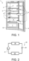
- the field-oriented electric drive 40 has a field-oriented control 43 which controls the converter 41.
- the field-oriented control 43 forms a cascade structure with internal current control loops on which an external speed control loop is superimposed, as is in principle familiar to those skilled in the art.
- the Fig. 5 partially shows this structure.
- the current control circuits preferably comprise a first current regulator 51 for the cross current i q and a second current regulator 52 for the longitudinal current i d .
- the two current regulators 51, 52 are in particular PI regulators.
- the field-oriented control 43 or the measuring device 42 is designed in such a way that it converts the phase currents i 1,2,3 of the three-phase synchronous motor 36 into rotor-fixed longitudinal and cross-current actual values i s related to the rotor of the three-phase synchronous motor 36 ,d , i s,q transformed.
- the deviation between the setpoint i q,set of the cross current i q and the actual cross current value i s,q is the input signal for the first current regulator 51
- the deviation between the longitudinal current setpoint i d,soll and the longitudinal current actual value i s,d is the input signal for the second current regulator 52.
- the output signals u q , u d of the two current regulators 51, 52 correspond to transformed electrical voltages, which are transformed into signals u w suitable for driving the converter 41 by means of a transformation 54 which is known in principle to those skilled in the art.
- the cross-current setpoint i q,soll results from this external speed control loop, which has a controller 53 and which is calculated depending on the setpoint speed nsoll and the actual speed nact.
- the controller 53 is in particular a PI controller.
- the longitudinal current setpoint i d,set is equal to zero.
- the field-oriented control 43 is a discrete field-oriented control 43.
- the clock or control frequency of the discrete field-oriented control 43 and thus of the two current regulators 51, 52 is, for example, 4 kHz.
- the field-oriented control 43 it is necessary to know the angular position of the rotor 38 relative to the stator 37 of the three-phase synchronous motor 36.
- the angular position is determined sensorlessly or without an encoder.
- the field-oriented regulated electric drive 40 is operated in a speed-controlled manner by means of the field-oriented control 43 and depending on an angular position of the rotor relative to the stator determined by means of the longitudinal and transverse currents actual values i s,d , i s,q and the mathematical model .
- the speed of the three-phase synchronous motor 36 is, for example, more than 1000 revolutions per minute.
- the speed of the three-phase synchronous motor 36 is initially controlled by speed-controlled operation of the regulated electric drive 40 by means of the field-oriented control 43 and depending on one by means of the longitudinal and cross currents and the mathematical model of the three-phase synchronous motor 36 determined angular position of the rotor 38 relative to the stator 37 is reduced until the speed reaches a predetermined limit speed.
- the limit speed is smaller than the speed during the operating phase and is, for example, 1000 revolutions per minute.
- the output signal u d of the second current controller 52 is superimposed with a high-frequency signal u HF , from which a signal u' d is created, so that during the remaining braking phase of the compressor the signal u w provided for controlling the converter 41 also provides information about the high-frequency signal u HF .
- the supply voltage provided for the three-phase synchronous motor 36 also has a high-frequency voltage component, as a result of which the phase currents i 1,2,3 and the longitudinal and cross-current actual values i s,d , i s,q have corresponding high-frequency current components.
- the longitudinal and transverse currents have actual values i s,d , i s,q , the high-frequency current components. Due to these high-frequency current components, it is then possible to determine an angular position of the rotor 38 necessary for the field-oriented control, even at relatively low speeds, and thus the speed of the three-phase synchronous motor 36 during the braking phase by speed-controlled operation of the regulated electric drive 43 by means of the field-oriented control 43 and depending on the angular position of the rotor 38 relative to the stator 37 determined by means of the high-frequency current components of the longitudinal and transverse currents actual values i s,d , i s,q until it comes to a standstill.
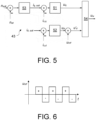
- the signal assigned to the high-frequency voltage (high-frequency signal u HF ) is rectangular and has a frequency equal to the controller frequency of the field-oriented control 43, i.e. in the case of the present exemplary embodiment it is 4 kHz.
- the two current regulators 51, 52 run, among other things, in a clock that is assigned to the regulator frequency of in particular 4 kHz.
- the course of the rectangular high-frequency signal u HF is in the Fig. 6 shown and in particular has a voltage of ⁇ 10 V.
- the pulse width modulated signal for the converter 41 runs, for example, at a clock rate corresponding to 8 kHz.
- the signal assigned to the high-frequency voltage (high-frequency signal u HF ) is alternately added and subtracted to the output signal u d of the second current regulator 52.
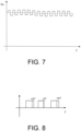
- the Fig. 7 shows the course of the signal u w provided for controlling the converter 41. The advantage is that demodulation is simplified. With the procedure presented, a wide variety of patterns can be impressed. The amplitude of the signal associated with the high-frequency voltage (high-frequency signal u HF ) was determined through experiments.
- the duty cycle lengths change accordingly Fig. 8 .
- the duty cycle is lengthened or shortened by a ⁇ T.
- the high-frequency current components of the longitudinal and transverse currents are obtained by the measuring device 42 carrying out a discrete measurement at a frequency that is twice as large as the frequency of the high-frequency signal u HF .
- the corresponding measurements are clocked in such a way that if two measurements are taken one after the other, one of the measurements is at the maximum and the other measurement at Minimum of the measured currents occurs.
- the high-frequency current components of the longitudinal and transverse currents can then be determined by subtracting the measured corresponding currents from two consecutive measurements.
- the phase currents i 1,2,3 are measured at 8 kHz.
- the phase currents i 1,2,3 are transformed into the longitudinal and transverse currents actual values i s,d , i s,q using a transformation known to those skilled in the art.
- the longitudinal and transverse currents also have high-frequency current components.
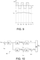
- the Fig. 9 shows the course of the longitudinal transverse flow.
- the longitudinal and transverse currents each have a high-frequency current component and a direct component. Since measurements are taken at twice the controller frequency, there are two measurements for each controller cycle for the longitudinal and transverse currents.
- the angular position of the rotor can be determined during the braking phase.
- the Fig. 10 shows an alternative structure of the field-oriented control 43, which is based on the so-called maximum torque per ampere principle.
- the longitudinal current setpoint i d,soll is not set to zero, but is determined by the external speed control loop like the cross-current setpoint i q,son .
- the signal generated by the external speed control loop is present at the output of the controller 53 and is assigned to the torque to be applied by the three-phase synchronous motor 36.
- the in the Fig. 10 Structure shown has a first function block 55 and a second function block 56.
- the first function block 55 is located between the output of the controller 53 of the external speed control loop and the difference between the cross-current setpoint i q,soll and the cross-current actual value i s,q .
- the second function block 56 is located between the output of the controller 53 of the external speed control loop and the difference between the longitudinal current setpoint i d,soll and the cross current actual value i d,q .
- the series current setpoint i d,soll and the transverse current setpoint i q,soll are determined based, among other things, on the basis of a relationship between the series and transverse inductances and on the basis of the signal determined by the external speed control loop. Since this relationship is non-linear, the longitudinal current setpoint i d,soll and the cross-current setpoint i q,soll are preferably determined using a look-up table stored in the function blocks 55, 56.
- the output signal of the first functional block 55 is the actual cross-current value i s,q and the output signal of the second functional block 56 is the longitudinal actual value i s,d .
- the functions of the two function blocks 55, 56 result from the characteristic fields of the longitudinal and transverse inductances L d , L q and are stored, for example, in a look-up table.
- the Fig. 11 shows, as a further example of a household appliance, a household tumble dryer 101, which has a corresponding field-oriented electric drive 43, the three-phase synchronous motor of which is part of a compressor 102 or is intended to drive the compressor 102.
- the compressor 102 is part of a heat pump circuit 103.
Landscapes
- Engineering & Computer Science (AREA)
- Power Engineering (AREA)
- Mechanical Engineering (AREA)
- General Engineering & Computer Science (AREA)
- Physics & Mathematics (AREA)
- Thermal Sciences (AREA)
- Computer Hardware Design (AREA)
- Control Of Ac Motors In General (AREA)
Applications Claiming Priority (1)
| Application Number | Priority Date | Filing Date | Title |
|---|---|---|---|
| DE102020203488.5A DE102020203488A1 (de) | 2020-03-18 | 2020-03-18 | Haushaltsgerät und Verfahren zum Betreiben eines Haushaltsgerätes |
Publications (2)
| Publication Number | Publication Date |
|---|---|
| EP3883121A1 EP3883121A1 (de) | 2021-09-22 |
| EP3883121B1 true EP3883121B1 (de) | 2024-01-31 |
Family
ID=74672188
Family Applications (1)
| Application Number | Title | Priority Date | Filing Date |
|---|---|---|---|
| EP21158179.8A Active EP3883121B1 (de) | 2020-03-18 | 2021-02-19 | Haushaltsgerät und verfahren zum betreiben eines haushaltsgerätes |
Country Status (4)
| Country | Link |
|---|---|
| EP (1) | EP3883121B1 (pl) |
| CN (1) | CN113497580B (pl) |
| DE (1) | DE102020203488A1 (pl) |
| PL (1) | PL3883121T3 (pl) |
Families Citing this family (8)
| Publication number | Priority date | Publication date | Assignee | Title |
|---|---|---|---|---|
| DE102022203427A1 (de) * | 2022-04-06 | 2023-10-12 | BSH Hausgeräte GmbH | Verfahren zum Betreiben eines Wechselrichters, Wechselrichter sowie Haushaltsgerät |
| DE102022206532A1 (de) | 2022-06-28 | 2023-12-28 | BSH Hausgeräte GmbH | Betreiben eines Haushaltsgeräts mit einem BLDC-Antriebsmotor |
| US12355374B2 (en) | 2023-02-09 | 2025-07-08 | Haier Us Appliance Solutions, Inc. | Field weakening for BLDC stand mixer |
| US12341459B2 (en) | 2023-02-09 | 2025-06-24 | Haier Us Appliance Solutions, Inc. | Method for avoiding stalled motor in a stand mixer with sensorless BLDC drive |
| US12551060B2 (en) | 2023-02-09 | 2026-02-17 | Haier Us Appliance Solutions, Inc. | High-frequency injection for sensorless control of a BLDC stand mixer |
| US12398717B2 (en) | 2023-02-09 | 2025-08-26 | Haier Us Appliance Solutions, Inc. | Single phase field oriented control for a linear compressor |
| US12395103B2 (en) | 2023-03-21 | 2025-08-19 | Haier Us Appliance Solutions, Inc. | Standstill angle detection for salient motors |
| US12553432B1 (en) | 2025-03-11 | 2026-02-17 | Haier Us Appliance Solutions, Inc. | Dynamic flux weakening for a single phase linear compressor |
Family Cites Families (17)
| Publication number | Priority date | Publication date | Assignee | Title |
|---|---|---|---|---|
| US3584276A (en) * | 1969-05-13 | 1971-06-08 | Allis Chalmers Mfg Co | Vehicle electric motor drive system |
| EP2023479B1 (de) | 2007-08-06 | 2014-04-16 | Baumüller Nürnberg Gmbh | System zur nahtlosen Geschwindigkeits- und/oder Lageermittlung einschließlich Stillstand bei einem Permanentmagnet-Läufer einer elektrischen Maschine |
| DE102008029910C5 (de) | 2008-06-24 | 2020-03-05 | BSH Hausgeräte GmbH | Verfahren zur Lastzustandserkennung einer Pumpe |
| JP5281339B2 (ja) * | 2008-09-01 | 2013-09-04 | 株式会社日立製作所 | 同期電動機の駆動システム、及びこれに用いる制御装置 |
| JP2010166638A (ja) * | 2009-01-13 | 2010-07-29 | Mitsubishi Electric Corp | 回転電機の制御装置 |
| JP5471255B2 (ja) | 2009-09-30 | 2014-04-16 | アイシン・エィ・ダブリュ株式会社 | 電動機駆動装置の制御装置 |
| JP5753474B2 (ja) * | 2010-10-19 | 2015-07-22 | 株式会社東芝 | 同期電動機制御装置 |
| CN102647145A (zh) * | 2012-04-01 | 2012-08-22 | 广东美的制冷设备有限公司 | 直流变频空调压缩机的控制方法 |
| US9548686B2 (en) * | 2013-05-03 | 2017-01-17 | Texas Instruments Incorporated | Angle/frequency selector in an electric motor controller architecture |
| EP2892148B1 (en) * | 2014-01-02 | 2021-09-22 | ABB Schweiz AG | Control system and method for an electric three-phase variable speed motor |
| US20150381091A1 (en) * | 2014-06-26 | 2015-12-31 | Nidec Motor Corporation | System and method for estimating motor resistance and temperature |
| DE102014217006A1 (de) * | 2014-08-26 | 2016-03-03 | BSH Hausgeräte GmbH | Verfahren zum Anhalten eines Verdichters und Verdichter eines Kältegerätes |
| DE102016203262A1 (de) | 2016-02-29 | 2017-08-31 | Zf Friedrichshafen Ag | Verfahren zur iterativen Ermittlung eines d- und q-Stromes zum Betreiben einer Synchronmaschine, Verfahren zum Betreiben einer Synchronmaschine und Steuergerät |
| DE102016210443A1 (de) | 2016-06-13 | 2017-12-14 | Robert Bosch Gmbh | Verfahren zur Anpassung einer Amplitude einer Spannungsinjektion einer mittels eines PWM-gesteuerten Wechselrichters gespeisten, rotierenden, mehrphasigen, elektrischen Maschine |
| CH712829A1 (de) * | 2016-08-22 | 2018-02-28 | Lakeview Innovation Ltd | Verfahren zur sensorlosen Steuerung eines PMSM-Motors. |
| DE102017211217A1 (de) | 2017-06-30 | 2019-01-03 | BSH Hausgeräte GmbH | Haushaltskältegerät mit einem Kältemittelkreislauf und Verfahren zum Betreiben eines Haushaltskältegeräts mit einem Kältemittelkreislauf |
| DE102017213069A1 (de) | 2017-07-28 | 2019-01-31 | Robert Bosch Gmbh | Verfahren zur Bestimmung einer Rotorlage einer elektrischen, rotierenden Maschine sowie eine elektrische, rotierende Maschine zur Durchführung eines solchen Verfahrens |
-
2020
- 2020-03-18 DE DE102020203488.5A patent/DE102020203488A1/de not_active Withdrawn
-
2021
- 2021-02-19 EP EP21158179.8A patent/EP3883121B1/de active Active
- 2021-02-19 PL PL21158179.8T patent/PL3883121T3/pl unknown
- 2021-03-16 CN CN202110279713.6A patent/CN113497580B/zh active Active
Also Published As
| Publication number | Publication date |
|---|---|
| EP3883121A1 (de) | 2021-09-22 |
| CN113497580A (zh) | 2021-10-12 |
| DE102020203488A1 (de) | 2021-09-23 |
| CN113497580B (zh) | 2024-06-07 |
| PL3883121T3 (pl) | 2024-05-06 |
Similar Documents
| Publication | Publication Date | Title |
|---|---|---|
| EP3883121B1 (de) | Haushaltsgerät und verfahren zum betreiben eines haushaltsgerätes | |
| DE69626073T2 (de) | Steuerungsvorrichtung für einen kühlschrank und kühlschrank mit einer solchen vorrichtung | |
| EP1992056B1 (de) | Verfahren zum prädiktiven regeln eines linearantriebs bzw. eines linearverdichters sowie prädiktiv geregelter linearantrieb bzw. linearverdichter | |
| DE10253789B4 (de) | Vorrichtung und Verfahren zur Betriebssteuerung eines Kolbenverdichters mit Linearmotor für Kühlgeräte | |
| DE10312234A1 (de) | Betriebssteuervorrichtung und -verfahren für einen Linearkompressor | |
| DE102009057433A1 (de) | Motorsteuerung und Trommelwaschmaschine | |
| EP3186880B1 (de) | Verfahren zum anhalten eines verdichters und verdichter eines kältegerätes | |
| WO2016030250A1 (de) | Verfahren zum bremsen eines verdichters und verdichter eines kältegerätes, klimageräts oder einer wärmepumpe sowie kältegerätes, klimageräts oder wärmepumpe damit | |
| EP3883122B1 (de) | Haushaltsgerät und verfahren zum betreiben eines haushaltsgerätes | |
| EP3338038B1 (de) | Haushaltskältegerät mit einem kältemittelkreislauf und verfahren zum betreiben eines haushaltskältegeräts mit einem kältemittelkreislauf | |
| EP3433926B1 (de) | Verfahren zur rotorpositionserkennung eines bldc motors eines hubkolbenverdichters, verdichtersteuerung zur durchführung des verfahrens und kältegerät mit dieser | |
| EP3262747B1 (de) | Haushaltskältegerät mit einem kältemittelkreislauf und verfahren zum betreiben eines haushaltskältegeräts mit einem kältemittelkreislauf | |
| WO2017076588A1 (de) | Haushaltskältegerät mit einem kältemittelkreislauf und verfahren zum betreiben eines haushaltskältegeräts mit einem kältemittelkreislauf | |
| EP4505594A1 (de) | Verfahren zum betreiben eines wechselrichters, wechselrichter sowie haushaltsgerät | |
| EP3428553B1 (de) | Haushaltskältegerät mit einem kältemittelkreislauf und verfahren zum betreiben eines haushaltskältegeräts mit einem kältemittelkreislauf | |
| WO2025021571A1 (de) | Betreiben eines linearkompressors eines haushaltsgeräts | |
| EP4548470A1 (de) | Betreiben eines haushaltsgeräts mit einem bldc-antriebsmotor | |
| WO2025016965A1 (de) | Kühlgerät und verfahren zum betreiben eines kühlgeräts | |
| WO2025016966A1 (de) | Kühlgerät und verfahren zum betreiben eines kühlgeräts | |
| DE102023208050A1 (de) | Verfahren zum Bestimmen einer drehtechnischen Blockierung eines rotierbaren Funktionsbauteils, Haushaltsgerät mit einem rotierbaren Funktionsbauteil | |
| WO2025016967A1 (de) | Kühlgerät und verfahren zum betreiben eines kühlgeräts |
Legal Events
| Date | Code | Title | Description |
|---|---|---|---|
| PUAI | Public reference made under article 153(3) epc to a published international application that has entered the european phase |
Free format text: ORIGINAL CODE: 0009012 |
|
| STAA | Information on the status of an ep patent application or granted ep patent |
Free format text: STATUS: THE APPLICATION HAS BEEN PUBLISHED |
|
| AK | Designated contracting states |
Kind code of ref document: A1 Designated state(s): AL AT BE BG CH CY CZ DE DK EE ES FI FR GB GR HR HU IE IS IT LI LT LU LV MC MK MT NL NO PL PT RO RS SE SI SK SM TR |
|
| STAA | Information on the status of an ep patent application or granted ep patent |
Free format text: STATUS: REQUEST FOR EXAMINATION WAS MADE |
|
| 17P | Request for examination filed |
Effective date: 20220322 |
|
| RBV | Designated contracting states (corrected) |
Designated state(s): AL AT BE BG CH CY CZ DE DK EE ES FI FR GB GR HR HU IE IS IT LI LT LU LV MC MK MT NL NO PL PT RO RS SE SI SK SM TR |
|
| GRAP | Despatch of communication of intention to grant a patent |
Free format text: ORIGINAL CODE: EPIDOSNIGR1 |
|
| STAA | Information on the status of an ep patent application or granted ep patent |
Free format text: STATUS: GRANT OF PATENT IS INTENDED |
|
| RIC1 | Information provided on ipc code assigned before grant |
Ipc: H02P 21/36 20160101ALI20230904BHEP Ipc: H02P 21/18 20160101ALI20230904BHEP Ipc: H02P 6/18 20160101ALI20230904BHEP Ipc: H02P 6/24 20060101ALI20230904BHEP Ipc: H02P 21/04 20060101AFI20230904BHEP |
|
| INTG | Intention to grant announced |
Effective date: 20230919 |
|
| GRAS | Grant fee paid |
Free format text: ORIGINAL CODE: EPIDOSNIGR3 |
|
| GRAA | (expected) grant |
Free format text: ORIGINAL CODE: 0009210 |
|
| STAA | Information on the status of an ep patent application or granted ep patent |
Free format text: STATUS: THE PATENT HAS BEEN GRANTED |
|
| AK | Designated contracting states |
Kind code of ref document: B1 Designated state(s): AL AT BE BG CH CY CZ DE DK EE ES FI FR GB GR HR HU IE IS IT LI LT LU LV MC MK MT NL NO PL PT RO RS SE SI SK SM TR |
|
| REG | Reference to a national code |
Ref country code: GB Ref legal event code: FG4D Free format text: NOT ENGLISH Ref country code: CH Ref legal event code: EP |
|
| REG | Reference to a national code |
Ref country code: DE Ref legal event code: R096 Ref document number: 502021002525 Country of ref document: DE |
|
| REG | Reference to a national code |
Ref country code: IE Ref legal event code: FG4D Free format text: LANGUAGE OF EP DOCUMENT: GERMAN |
|
| REG | Reference to a national code |
Ref country code: LT Ref legal event code: MG9D |
|
| REG | Reference to a national code |
Ref country code: NL Ref legal event code: MP Effective date: 20240131 |
|
| PG25 | Lapsed in a contracting state [announced via postgrant information from national office to epo] |
Ref country code: IS Free format text: LAPSE BECAUSE OF FAILURE TO SUBMIT A TRANSLATION OF THE DESCRIPTION OR TO PAY THE FEE WITHIN THE PRESCRIBED TIME-LIMIT Effective date: 20240531 |
|
| PG25 | Lapsed in a contracting state [announced via postgrant information from national office to epo] |
Ref country code: LT Free format text: LAPSE BECAUSE OF FAILURE TO SUBMIT A TRANSLATION OF THE DESCRIPTION OR TO PAY THE FEE WITHIN THE PRESCRIBED TIME-LIMIT Effective date: 20240131 |
|
| PG25 | Lapsed in a contracting state [announced via postgrant information from national office to epo] |
Ref country code: GR Free format text: LAPSE BECAUSE OF FAILURE TO SUBMIT A TRANSLATION OF THE DESCRIPTION OR TO PAY THE FEE WITHIN THE PRESCRIBED TIME-LIMIT Effective date: 20240501 |
|
| PG25 | Lapsed in a contracting state [announced via postgrant information from national office to epo] |
Ref country code: RS Free format text: LAPSE BECAUSE OF FAILURE TO SUBMIT A TRANSLATION OF THE DESCRIPTION OR TO PAY THE FEE WITHIN THE PRESCRIBED TIME-LIMIT Effective date: 20240430 Ref country code: HR Free format text: LAPSE BECAUSE OF FAILURE TO SUBMIT A TRANSLATION OF THE DESCRIPTION OR TO PAY THE FEE WITHIN THE PRESCRIBED TIME-LIMIT Effective date: 20240131 Ref country code: NL Free format text: LAPSE BECAUSE OF FAILURE TO SUBMIT A TRANSLATION OF THE DESCRIPTION OR TO PAY THE FEE WITHIN THE PRESCRIBED TIME-LIMIT Effective date: 20240131 |
|
| PG25 | Lapsed in a contracting state [announced via postgrant information from national office to epo] |
Ref country code: ES Free format text: LAPSE BECAUSE OF FAILURE TO SUBMIT A TRANSLATION OF THE DESCRIPTION OR TO PAY THE FEE WITHIN THE PRESCRIBED TIME-LIMIT Effective date: 20240131 |
|
| PG25 | Lapsed in a contracting state [announced via postgrant information from national office to epo] |
Ref country code: RS Free format text: LAPSE BECAUSE OF FAILURE TO SUBMIT A TRANSLATION OF THE DESCRIPTION OR TO PAY THE FEE WITHIN THE PRESCRIBED TIME-LIMIT Effective date: 20240430 Ref country code: NO Free format text: LAPSE BECAUSE OF FAILURE TO SUBMIT A TRANSLATION OF THE DESCRIPTION OR TO PAY THE FEE WITHIN THE PRESCRIBED TIME-LIMIT Effective date: 20240430 Ref country code: NL Free format text: LAPSE BECAUSE OF FAILURE TO SUBMIT A TRANSLATION OF THE DESCRIPTION OR TO PAY THE FEE WITHIN THE PRESCRIBED TIME-LIMIT Effective date: 20240131 Ref country code: LT Free format text: LAPSE BECAUSE OF FAILURE TO SUBMIT A TRANSLATION OF THE DESCRIPTION OR TO PAY THE FEE WITHIN THE PRESCRIBED TIME-LIMIT Effective date: 20240131 Ref country code: IS Free format text: LAPSE BECAUSE OF FAILURE TO SUBMIT A TRANSLATION OF THE DESCRIPTION OR TO PAY THE FEE WITHIN THE PRESCRIBED TIME-LIMIT Effective date: 20240531 Ref country code: HR Free format text: LAPSE BECAUSE OF FAILURE TO SUBMIT A TRANSLATION OF THE DESCRIPTION OR TO PAY THE FEE WITHIN THE PRESCRIBED TIME-LIMIT Effective date: 20240131 Ref country code: GR Free format text: LAPSE BECAUSE OF FAILURE TO SUBMIT A TRANSLATION OF THE DESCRIPTION OR TO PAY THE FEE WITHIN THE PRESCRIBED TIME-LIMIT Effective date: 20240501 Ref country code: FI Free format text: LAPSE BECAUSE OF FAILURE TO SUBMIT A TRANSLATION OF THE DESCRIPTION OR TO PAY THE FEE WITHIN THE PRESCRIBED TIME-LIMIT Effective date: 20240131 Ref country code: ES Free format text: LAPSE BECAUSE OF FAILURE TO SUBMIT A TRANSLATION OF THE DESCRIPTION OR TO PAY THE FEE WITHIN THE PRESCRIBED TIME-LIMIT Effective date: 20240131 Ref country code: BG Free format text: LAPSE BECAUSE OF FAILURE TO SUBMIT A TRANSLATION OF THE DESCRIPTION OR TO PAY THE FEE WITHIN THE PRESCRIBED TIME-LIMIT Effective date: 20240131 |
|
| PG25 | Lapsed in a contracting state [announced via postgrant information from national office to epo] |
Ref country code: PT Free format text: LAPSE BECAUSE OF FAILURE TO SUBMIT A TRANSLATION OF THE DESCRIPTION OR TO PAY THE FEE WITHIN THE PRESCRIBED TIME-LIMIT Effective date: 20240531 |
|
| PG25 | Lapsed in a contracting state [announced via postgrant information from national office to epo] |
Ref country code: SE Free format text: LAPSE BECAUSE OF FAILURE TO SUBMIT A TRANSLATION OF THE DESCRIPTION OR TO PAY THE FEE WITHIN THE PRESCRIBED TIME-LIMIT Effective date: 20240131 Ref country code: PT Free format text: LAPSE BECAUSE OF FAILURE TO SUBMIT A TRANSLATION OF THE DESCRIPTION OR TO PAY THE FEE WITHIN THE PRESCRIBED TIME-LIMIT Effective date: 20240531 Ref country code: LV Free format text: LAPSE BECAUSE OF FAILURE TO SUBMIT A TRANSLATION OF THE DESCRIPTION OR TO PAY THE FEE WITHIN THE PRESCRIBED TIME-LIMIT Effective date: 20240131 |
|
| REG | Reference to a national code |
Ref country code: CH Ref legal event code: PL |
|
| PG25 | Lapsed in a contracting state [announced via postgrant information from national office to epo] |
Ref country code: DK Free format text: LAPSE BECAUSE OF FAILURE TO SUBMIT A TRANSLATION OF THE DESCRIPTION OR TO PAY THE FEE WITHIN THE PRESCRIBED TIME-LIMIT Effective date: 20240131 |
|
| PG25 | Lapsed in a contracting state [announced via postgrant information from national office to epo] |
Ref country code: SM Free format text: LAPSE BECAUSE OF FAILURE TO SUBMIT A TRANSLATION OF THE DESCRIPTION OR TO PAY THE FEE WITHIN THE PRESCRIBED TIME-LIMIT Effective date: 20240131 |
|
| PG25 | Lapsed in a contracting state [announced via postgrant information from national office to epo] |
Ref country code: LU Free format text: LAPSE BECAUSE OF NON-PAYMENT OF DUE FEES Effective date: 20240219 |
|
| PG25 | Lapsed in a contracting state [announced via postgrant information from national office to epo] |
Ref country code: CH Free format text: LAPSE BECAUSE OF NON-PAYMENT OF DUE FEES Effective date: 20240229 |
|
| PG25 | Lapsed in a contracting state [announced via postgrant information from national office to epo] |
Ref country code: CZ Free format text: LAPSE BECAUSE OF FAILURE TO SUBMIT A TRANSLATION OF THE DESCRIPTION OR TO PAY THE FEE WITHIN THE PRESCRIBED TIME-LIMIT Effective date: 20240131 Ref country code: EE Free format text: LAPSE BECAUSE OF FAILURE TO SUBMIT A TRANSLATION OF THE DESCRIPTION OR TO PAY THE FEE WITHIN THE PRESCRIBED TIME-LIMIT Effective date: 20240131 |
|
| PG25 | Lapsed in a contracting state [announced via postgrant information from national office to epo] |
Ref country code: SK Free format text: LAPSE BECAUSE OF FAILURE TO SUBMIT A TRANSLATION OF THE DESCRIPTION OR TO PAY THE FEE WITHIN THE PRESCRIBED TIME-LIMIT Effective date: 20240131 |
|
| PG25 | Lapsed in a contracting state [announced via postgrant information from national office to epo] |
Ref country code: SM Free format text: LAPSE BECAUSE OF FAILURE TO SUBMIT A TRANSLATION OF THE DESCRIPTION OR TO PAY THE FEE WITHIN THE PRESCRIBED TIME-LIMIT Effective date: 20240131 Ref country code: SK Free format text: LAPSE BECAUSE OF FAILURE TO SUBMIT A TRANSLATION OF THE DESCRIPTION OR TO PAY THE FEE WITHIN THE PRESCRIBED TIME-LIMIT Effective date: 20240131 Ref country code: RO Free format text: LAPSE BECAUSE OF FAILURE TO SUBMIT A TRANSLATION OF THE DESCRIPTION OR TO PAY THE FEE WITHIN THE PRESCRIBED TIME-LIMIT Effective date: 20240131 Ref country code: LU Free format text: LAPSE BECAUSE OF NON-PAYMENT OF DUE FEES Effective date: 20240219 Ref country code: EE Free format text: LAPSE BECAUSE OF FAILURE TO SUBMIT A TRANSLATION OF THE DESCRIPTION OR TO PAY THE FEE WITHIN THE PRESCRIBED TIME-LIMIT Effective date: 20240131 Ref country code: DK Free format text: LAPSE BECAUSE OF FAILURE TO SUBMIT A TRANSLATION OF THE DESCRIPTION OR TO PAY THE FEE WITHIN THE PRESCRIBED TIME-LIMIT Effective date: 20240131 Ref country code: CZ Free format text: LAPSE BECAUSE OF FAILURE TO SUBMIT A TRANSLATION OF THE DESCRIPTION OR TO PAY THE FEE WITHIN THE PRESCRIBED TIME-LIMIT Effective date: 20240131 Ref country code: CH Free format text: LAPSE BECAUSE OF NON-PAYMENT OF DUE FEES Effective date: 20240229 |
|
| REG | Reference to a national code |
Ref country code: DE Ref legal event code: R097 Ref document number: 502021002525 Country of ref document: DE |
|
| PG25 | Lapsed in a contracting state [announced via postgrant information from national office to epo] |
Ref country code: MC Free format text: LAPSE BECAUSE OF FAILURE TO SUBMIT A TRANSLATION OF THE DESCRIPTION OR TO PAY THE FEE WITHIN THE PRESCRIBED TIME-LIMIT Effective date: 20240131 |
|
| PG25 | Lapsed in a contracting state [announced via postgrant information from national office to epo] |
Ref country code: MC Free format text: LAPSE BECAUSE OF FAILURE TO SUBMIT A TRANSLATION OF THE DESCRIPTION OR TO PAY THE FEE WITHIN THE PRESCRIBED TIME-LIMIT Effective date: 20240131 |
|
| PG25 | Lapsed in a contracting state [announced via postgrant information from national office to epo] |
Ref country code: IT Free format text: LAPSE BECAUSE OF FAILURE TO SUBMIT A TRANSLATION OF THE DESCRIPTION OR TO PAY THE FEE WITHIN THE PRESCRIBED TIME-LIMIT Effective date: 20240131 |
|
| PLBE | No opposition filed within time limit |
Free format text: ORIGINAL CODE: 0009261 |
|
| STAA | Information on the status of an ep patent application or granted ep patent |
Free format text: STATUS: NO OPPOSITION FILED WITHIN TIME LIMIT |
|
| REG | Reference to a national code |
Ref country code: BE Ref legal event code: MM Effective date: 20240229 |
|
| PG25 | Lapsed in a contracting state [announced via postgrant information from national office to epo] |
Ref country code: IT Free format text: LAPSE BECAUSE OF FAILURE TO SUBMIT A TRANSLATION OF THE DESCRIPTION OR TO PAY THE FEE WITHIN THE PRESCRIBED TIME-LIMIT Effective date: 20240131 |
|
| 26N | No opposition filed |
Effective date: 20241101 |
|
| PG25 | Lapsed in a contracting state [announced via postgrant information from national office to epo] |
Ref country code: BE Free format text: LAPSE BECAUSE OF NON-PAYMENT OF DUE FEES Effective date: 20240229 |
|
| PG25 | Lapsed in a contracting state [announced via postgrant information from national office to epo] |
Ref country code: FR Free format text: LAPSE BECAUSE OF NON-PAYMENT OF DUE FEES Effective date: 20240331 |
|
| PG25 | Lapsed in a contracting state [announced via postgrant information from national office to epo] |
Ref country code: IE Free format text: LAPSE BECAUSE OF NON-PAYMENT OF DUE FEES Effective date: 20240219 |
|
| PG25 | Lapsed in a contracting state [announced via postgrant information from national office to epo] |
Ref country code: IE Free format text: LAPSE BECAUSE OF NON-PAYMENT OF DUE FEES Effective date: 20240219 Ref country code: FR Free format text: LAPSE BECAUSE OF NON-PAYMENT OF DUE FEES Effective date: 20240331 Ref country code: BE Free format text: LAPSE BECAUSE OF NON-PAYMENT OF DUE FEES Effective date: 20240229 |
|
| PGFP | Annual fee paid to national office [announced via postgrant information from national office to epo] |
Ref country code: DE Payment date: 20240703 Year of fee payment: 5 |
|
| PG25 | Lapsed in a contracting state [announced via postgrant information from national office to epo] |
Ref country code: SI Free format text: LAPSE BECAUSE OF FAILURE TO SUBMIT A TRANSLATION OF THE DESCRIPTION OR TO PAY THE FEE WITHIN THE PRESCRIBED TIME-LIMIT Effective date: 20240131 |
|
| PGFP | Annual fee paid to national office [announced via postgrant information from national office to epo] |
Ref country code: AT Payment date: 20250417 Year of fee payment: 5 |
|
| PGFP | Annual fee paid to national office [announced via postgrant information from national office to epo] |
Ref country code: PL Payment date: 20250207 Year of fee payment: 5 |
|
| PGFP | Annual fee paid to national office [announced via postgrant information from national office to epo] |
Ref country code: TR Payment date: 20250210 Year of fee payment: 5 |
|
| PG25 | Lapsed in a contracting state [announced via postgrant information from national office to epo] |
Ref country code: CY Free format text: LAPSE BECAUSE OF FAILURE TO SUBMIT A TRANSLATION OF THE DESCRIPTION OR TO PAY THE FEE WITHIN THE PRESCRIBED TIME-LIMIT; INVALID AB INITIO Effective date: 20210219 |
|
| PG25 | Lapsed in a contracting state [announced via postgrant information from national office to epo] |
Ref country code: HU Free format text: LAPSE BECAUSE OF FAILURE TO SUBMIT A TRANSLATION OF THE DESCRIPTION OR TO PAY THE FEE WITHIN THE PRESCRIBED TIME-LIMIT; INVALID AB INITIO Effective date: 20210219 |
|
| GBPC | Gb: european patent ceased through non-payment of renewal fee |
Effective date: 20250219 |
|
| PG25 | Lapsed in a contracting state [announced via postgrant information from national office to epo] |
Ref country code: GB Free format text: LAPSE BECAUSE OF NON-PAYMENT OF DUE FEES Effective date: 20250219 |